EP1485892B1 - Method and apparatus for tactile cueing of aircraft controls - Google Patents
Method and apparatus for tactile cueing of aircraft controls Download PDFInfo
- Publication number
- EP1485892B1 EP1485892B1 EP03745181A EP03745181A EP1485892B1 EP 1485892 B1 EP1485892 B1 EP 1485892B1 EP 03745181 A EP03745181 A EP 03745181A EP 03745181 A EP03745181 A EP 03745181A EP 1485892 B1 EP1485892 B1 EP 1485892B1
- Authority
- EP
- European Patent Office
- Prior art keywords
- tactile
- cueing
- aircraft
- stepper motor
- control mechanism
- Prior art date
- Legal status (The legal status is an assumption and is not a legal conclusion. Google has not performed a legal analysis and makes no representation as to the accuracy of the status listed.)
- Expired - Lifetime
Links
Images


Classifications
-
- B—PERFORMING OPERATIONS; TRANSPORTING
- B64—AIRCRAFT; AVIATION; COSMONAUTICS
- B64C—AEROPLANES; HELICOPTERS
- B64C27/00—Rotorcraft; Rotors peculiar thereto
- B64C27/54—Mechanisms for controlling blade adjustment or movement relative to rotor head, e.g. lag-lead movement
- B64C27/56—Mechanisms for controlling blade adjustment or movement relative to rotor head, e.g. lag-lead movement characterised by the control initiating means, e.g. manually actuated
-
- B—PERFORMING OPERATIONS; TRANSPORTING
- B64—AIRCRAFT; AVIATION; COSMONAUTICS
- B64C—AEROPLANES; HELICOPTERS
- B64C13/00—Control systems or transmitting systems for actuating flying-control surfaces, lift-increasing flaps, air brakes, or spoilers
- B64C13/24—Transmitting means
- B64C13/26—Transmitting means without power amplification or where power amplification is irrelevant
- B64C13/28—Transmitting means without power amplification or where power amplification is irrelevant mechanical
- B64C13/345—Transmitting means without power amplification or where power amplification is irrelevant mechanical with artificial feel
Definitions
- the present invention relates to aircraft control systems.
- the present invention relates to tactile cueing of aircraft control systems.
- a tactile cue that shakes the control is provided.
- the tactile cue is only a classifier, i. e. , either the pilot is violating a limit, or he is not. There is no"leading"information or forewarning.
- These methods are typically the most easy to implement, but they do not provide any information regarding the degree of limit exceedance.
- Examples of known tactile cueing system (11) for an aircraft are disclosed in US 4 664 346 A , WO 99/03728 A1 , and US 5 986 582 A .
- WO 99/03728 A1 discloses a mechanical stop device which imparts a rotation on a shaft as the collective is pivoted thereby rotating two stops, the shaft being connected to an electric servo control, a reduction gearbox , and a friction coupling.
- FDR Flight Data Recorder
- HUMS Health and Usage Monitoring Systems
- the tactile cueing system for an aircraft of the invention is characterized by the features claimed in the characterizing part of claim 1.
- tactile cueing system comprising a microswitch operably associated with the force gradient spring cartridge , wherein the microswitch is configured to prevent inadvertent motion of the control mechanism when a predicted valve of an operational parameter drops below a limit.
- the method and apparatus for tactile cueing of aircraft controls comprises a parameter prediction and a "soft-stop" tactile cue.
- the parameter prediction uses a computer, associated software, and sensors of control position, engine parameters, and rotor performance to predict a future value of certain parameters based upon current values.
- Any number of algorithms can be applied to the prediction problem, including, but not limited to, Kalman filtering, extended Kalman filtering, linear prediction, trending, multi-variable surface fits of measured data, simple analytical expressions, artificial neural networks, and fuzzy logic.
- Some of the sensors measure current values of air data, such as airspeed and rate of descent.
- Other sensors measure performance parameters, such as engine torque, exhaust gas temperature, and rotor speed.
- Still other sensors measure pilot inputs through control displacement and rate information. All of this sensed data is sent to the aircraft's flight control computers to prepare the data for analysis.
- the parameter prediction is made of a future value of the desired performance parameters. This predicted value is then passed to a soft-stop cueing algorithm.
- the soft-stop algorithm is a "floating ground” algorithm that does not require additional sensed positions of either side of the spring cartridge. This reduces the cost of the system and increases reliability by reducing complexity.
- the use of a stepper motor combines braking capability and precise position control of the "floating ground" side of the spring cartridge without the requirement of additional sensors.
- the soft-stop tactile cue is achieved by use of a force gradient spring cartridge placed in parallel with an existing control linkage. One end of the spring cartridge is attached to the existing control linkage, and the other end of the spring cartridge is attached to an actuator arm of a stepper motor. A microswitch is placed in-line with the spring cartridge to prevent inadvertent stick motion when the predicted torque drops below the limit torque and the stepper motor is ready to return to a free-wheeling mode. Furthermore, a stick shaker can be attached to the collective stick to provide an additional tactile cue.
- the existing control linkage drives one end of the spring cartridge.
- the stepper motor shaft is free to move in either direction as dictated by forces applied to the actuator arm.
- the forces applied to the actuator arm are those transmitted by the spring cartridge and are due to the motion of the collective.
- the actual and predicted values of torque are below the torque limit.
- the software directs these activities.
- an engage flag for the stepper motor is set true, making the stepper motor act like a magnetic brake.
- the microswitch shows its true state indicating that the spring cartridge is in tension.
- the spring cartridge then supplies a resistive force consisting of a breakout force and an increasing force proportional to the amount of exceedance.
- the microswitch changes to its false state causing the stepper motor to revert to free-wheeling mode, thereby removing any resistance to corrective action.
- the engage flag changes to true, the current location of the collective is recorded and serves as an initial value for both the actual location and the commanded location of the collective stick.
- a collective limit position (CLIP) is calculated. This calculation determines where the collective should be so that the torque will just equal the limit at the future time, referred to as the prediction horizon.
- the CLIP is measured relative to the current location of the collective position, so only a change or delta needs to be calculated. The calculation itself comes from the amount the torque exceeds the limit multiplied by the gain relating inches of collective stick to change in torque.
- the CLIP is then added to the commanded location for the collective step.
- a step command is issued to the stepper motor. If the commanded location is below the actual location, a "down” step is issued. If the commanded location is above the actual location, an “up” step is issued. Coincident commanded and actual location issues a "zero” step. The stepper motor then moves one end of the spring cartridge accordingly. If the pilot maintains just the breakout force on the collective, the stepper motor actually drives the pilot's hand to track exactly the torque limit. If the pilot maintains the collective in one position, he feels the force modulate according to the degree of exceedance.
- the stick shaker is activated.
- stepper motor engagement and direction involves a truth table that uses values of torque exceedance, current and previous stepper motor engagement, and state of the microswitch.
- An important aspect of the present invention is the fact that the corrective action by the pilot for torque exceedance, rotor droop, and exhaust gas temperature is to push the collective down.
- the system need only determine if any exceedance exists individually. If so, the system starts the cueing process, then calculates the CLIP for each parameter that is exceeding its limit, and uses the most conservative answer.
- the limits are not constants, but are instead functions of airspeed and other parameters.
- the torque limit changes in step fashion at a certain speed, for example V q .
- the limit value is slowly changed as a function of airspeed proximity to V q , and the rate at which the airspeed approaches V q .
- the present invention provides many significant benefits and advantages, including: (1) the use of electro-hydraulic actuators for inducing control force feel is avoided, resulting in less complexity, more reliability, and lower costs for maintenance and repair; (2) the tactile cueing stimulates a sense that is not already saturated, thereby requiring significantly reduced cognitive effort; (3) an algorithm that continuously updates the limit position of all parameters over which the collective has significant influence is used; (4) pilot intent is not interfered with, so that if a pilot wants to pull through the cue, this system will resist, but not stop that action; (5) the system employs a crisp, unambiguous cue with an optional shaking cue, as opposed to a shaking cue alone; (6) the crisp tactile cues permit more accurate tracking of the limit than do shaking cues; (7) inadvertent over-torque events can be eliminated, while reducing pilot workload; (8) helicopter operational safety is improved by reducing pilot workload associated with avoiding certain operational parameter exceedances during demanding maneuvers; (9) more than one limit can be cued by the collective stick,
- the method and apparatus of the present invention uses tactile feedback to cue a pilot of impending exceedance of one or more operational parameters of an aircraft.
- the present invention enables the pilot to maintain "eyes-out-the-window" references during high-workload maneuvering tasks.
- the present invention is described with regard to a helicopter and HUMS parameters, it should be understood that the present invention is not limited to such applications, but may be used as an independent system on any rotorcraft or other aircraft, with or without a HUMS.
- the cueing required for closed-loop torque management must be timely and unambiguous. Simply introducing a soft-stop at the static collective position where an exceedance is first expected to occur is insufficient due to the false relief cues that may result. For example, if the collective is lowered to relieve the force cue, the aircraft could still be in an exceedance condition due to the application of other control inputs. In other situations, the cueing must be able to adapt to airspeed dependent limits on torque.
- Aircraft 10 includes a fuselage 12, a drive means 18, and a main rotor 14. Torque imparted to fuselage 12 by main rotor 14 is counter-acted by a tail rotor assembly 16 mounted on a tail portion 22 of fuselage 12. Main rotor 14 and tail rotor assembly 16 are powered by drive means 18 under the control of a pilot in a cockpit 20.
- Tactile cueing system 11 includes a force gradient spring cartridge 13 placed in parallel with an existing control linkage 15. One end of spring cartridge 13 is coupled to existing control linkage 15, and the other end of spring cartridge 13 is coupled to an actuator arm 17 of an electric stepper motor 19. Control linkage 15 is coupled to a collective 21 via a mixing lever 23.
- a switching means, or microswitch 25, is operably associated with spring cartridge 13, preferably by being disposed in-line with spring cartridge 13, to prevent inadvertent motion of collective 21 when the predicted torque drops below the limit torque and stepper motor 19 is ready to return to a free-wheeling mode.
- a position transducer 27 is operably associated with control linkage 15 to provide position data for control linkage 15.
- a stick shaker 29 may be optionally attached to collective 21 to provide an additional tactile cue.
- stepper motor 19, microswitch 25, position transducer 27, and stick shaker 29 are all coupled to a system computer 31.
- FIG. 3 one exemplary configuration of the simplified representation of tactile cueing system 11 of Figure 2 is illustrated.
- spring cartridge 13, control linkage 15, stepper motor 19, mixing lever 23, and microswitch 25 are disposed beneath the cabin floor of aircraft 10.
- tactile cueing system 11 is shown in a more detailed schematic.
- Figure 4 illustrates the inter-relation of tactile cueing system 11 to other control systems of aircraft 10.
- Tactile cueing system 11 is controlled by a collective cueing processor (CCP) 51 that is powered by aircraft 10.
- CCP 51 is preferably based on the HUMS Processor Module (HPM) available from Smiths Aerospace Electronic Systems. If aircraft 10 does not include a HUMS, then CCP 51 may comprise a stand alone unit.
- CCP 51 may be performed by a flight control computer 59, provided aircraft 10 includes such a flight control computer 59, and that flight control computer 59 has sufficient computing capacity to perform the processing functions of CCP 51.
- CCP 51 may also be a stand alone unit in applications in which aircraft 10 includes a HUMS.
- the HPM is preferably a 603e PowerPC processor based system with serial and discrete input/output capability. As well as having specialized avionics interface devices, the HPM is also fitted with four universal asynchronous receiver/transmitter (UART) serial interfaces 57, over which the HPM receives data from aircraft flight control computers 59.
- UART universal asynchronous receiver/transmitter
- Interface card 55 is used to enable CCP 51 to generate discrete output signals to drive the cueing devices. Interface card 55 inverts the signals to ensure that if power is removed from CCP 51, stepper motor 19 is allowed to free wheel, stick shaker 29 and the over-torque indicator are disabled, and failure warning indicator 53 is illuminated.
- CCP 51 uses flight data information from a data acquisition system of aircraft 10 to identify the aircraft flight condition and predict the torque level. When the torque is predicted to exceed the transmission limit, a cue is provided.
- the cue can be generated in a number of forms, including collective force cueing, a stick shaker, voice warning, or visual warning.
- control linkage 15 drives one end of spring cartridge 13.
- the shaft of stepper motor 19 is free to move in either direction as dictated by forces applied to actuator arm 17.
- the forces applied to actuator arm 17 are those transmitted by spring cartridge 13 and are due to the motion of collective 21.
- the actual and predicted values of engine torque are below the torque limit.
- the system computer 31 directs these activities.
- stepper motor 19 acts like a magnetic brake.
- microswitch 25 shows its true state indicating that spring cartridge 13 is in tension. Spring cartridge 13 then supplies a resistive force consisting of a breakout force and an increasing force proportional to the amount of exceedance.
- microswitch 25 changes to its false state causing stepper motor 19 to revert to free-wheeling mode, thereby removing any resistance to corrective action.
- the engage flag changes to true, the current location of collective 21 is recorded and serves as an initial value for both the actual location and the commanded location of collective 21.
- a collective limit position (CLIP) is calculated. This calculation determines where collective 21 should be so that the torque will just equal the limit at the future time, referred to as the prediction horizon.
- the CLIP is measured relative to the current location of the collective position, so only a change or delta needs to be calculated. The calculation itself comes from the amount the torque exceeds the limit multiplied by the gain relating inches of collective stick to change in torque.
- the CLIP is then added to the commanded location for the collective step.
- step command is issued to stepper motor 19. If the commanded location is below the actual location, a "down” step is issued. If the commanded location is above the actual location, an "up” step is issued. Coincident commanded and actual location issues a "zero” step. Stepper motor 19 then moves one end of spring cartridge 13 accordingly. If the pilot maintains just the breakout force on collective 21, stepper motor 19 actually drives the pilot's hand to track exactly the torque limit. If the pilot maintains collective 21 in one position, he feels the force modulate according to the degree of exceedance.
- the force cue preferably consists of an 8-pound breakout force at the torque limit plus a 1.4 pound per inch force gradient. Because collective position for limit torque will vary with flight condition and maneuver requirements, the resulting position is a dynamic value that requires constant update.
- stepper motor engagement and direction involves a truth table that uses values of torque exceedance, current and previous stepper motor engagement, and state of the microswitch.
- an important aspect of the present invention is the fact that the corrective action by the pilot for torque exceedance, rotor droop, and exhaust gas temperature is to push collective 21 down.
- the system need only determine if any exceedance exists individually. If so, tactile cueing system 11 starts the cueing process, then calculates the CLIP for each parameter that is exceeding its limit, and uses the most conservative answer.
- the limits are not constants, but are instead functions of airspeed and other parameters.
- the torque limit changes in step fashion at a certain speed, for example V q .
- the limit value is slowly changed as a function of airspeed proximity to V q , and the rate at which the airspeed approaches V q .
- Flight control computers 59 provide flight data to control software residing on CCP 51, which sends applicable tactile cues to the pilot.
- the control software uses current control positions and aircraft flight parameters from flight control computers 59 to perform a neural network based prediction of future mast torque. A prediction using the collective rate is also possible to compensate for aggressive collective inputs.
- CCP 51 controls the engagement and position of stepper motor 19.
- tactile cueing system 11 uses flight data available from a typical HUMS system to provide the required input for tactile cueing.
- a major cost driver for a typical FDR or HUMS installation involves the acquisition of flight data from the predominately analogue transducers found on civil rotorcraft, and the processors required to implement HUMS applications. This means that the addition of tactile cueing system 11 on an aircraft already equipped with HUMS can be achieved at minimum additional cost.
- FIG. 5 a table of flight data parameters is illustrated.
- Three separate polynomial neural networks (PNN) predict the torque simultaneously. These predictions are compared to the current torque, and a final weighted average for future torque is produced.
- the preferred PNNs were developed using the group method of data handling (GMDH) algorithm.
- GMDH group method of data handling
- a major feature of the GMDH algorithm is that it produces deterministic algebraic expressions suitable for meeting software certification requirements.
- Each PNN uses an independent set of flight data parameters from aircraft 10.
- the parameters are preferably grouped into the following categories: airframe, engine and pilot.
- the algorithm package has been written such that a different set of PNNs can be used depending on the current aircraft flight condition. Two exemplary flight conditions are: (1) above 40 knots; and (2) below 40 knots.
- tactile cueing system 11 comprises a parameter prediction and a "soft-stop" tactile cue.
- the parameter prediction uses a computer, associated software, and sensors of control position, engine parameters, and rotor performance to predict a future value of certain parameters based upon current values. Any number of algorithms can be applied to the prediction problem, including, but not limited to, Kalman filtering, extended Kalman filtering, linear prediction, trending, multi-variable surface fits of measured data, simple analytical expressions, artificial neural networks, and fuzzy logic.
- Some of the sensors measure current values of air data, such as airspeed and rate of descent.
- Other sensors measure performance parameters, such as engine torque, exhaust gas temperature, and rotor speed.
- Still other sensors measure pilot inputs through control displacement and rate information. All of this sensed data is sent to the aircraft's flight control computers to prepare the data for analysis.
- the parameter prediction is made of a future value of the desired performance parameters.
- This predicted value is then passed to a soft-stop cueing algorithm.
- the soft-stop algorithm is a "floating ground” algorithm. This means that a fixed reference point for the position of spring cartridge 13 is not necessary. By utilizing this floating ground algorithm, additional sensors to detect the positions of either side of spring cartridge 13 are not necessary. This reduces the cost of the system and increases reliability by reducing complexity.
- the use of stepper motor 19 combines braking capability and precise position control of the floating ground side of spring cartridge 13 without the requirement of additional sensors.
- the cueing algorithm functions as an inverse model.
- the maximum of the predicted torque and the measured torque is known as the test torque.
- the test torque is compared to the torque limit, which varies with flight condition. If the test torque rises above the torque limit, the motor engages, establishing the ground for spring cartridge 13. The pilot will feel the breakout force, and an increasing gradient force with continued upward movement of collective 21.
- determination of the test torque value is an ongoing process, and commands to actuate stepper motor 19 are continuously computed in order to drive the cue to correspond with the limit collective position. If the pilot lowers collective 21, decreasing the torque, stepper motor 19 is disengaged and becomes freewheeling. The inertia of stepper motor 19 is small enough that no appreciable inertial resistance to collective motion is detected.
- the control algorithm also adapts to discontinuous torque limits within the helicopter flight envelope, using a ramp that is a function of the proximity and rate of approach to the discontinuity.
- Tactile cueing system 11 results in significant advantages in terms of system airworthiness considerations.
- tactile cueing system 11 is transparent to the pilot.
- the pilot can still apply any required collective input by pulling through the breakout and gradient force. This is a very intuitive reaction.
- stepper motor 19 makes the possibility of an actuator hard-over very improbable. In the event of a mechanical jam the pilot can still fly through spring cartridge 13 without objectionable collective forces.
Landscapes
- Engineering & Computer Science (AREA)
- Mechanical Engineering (AREA)
- Aviation & Aerospace Engineering (AREA)
- Automation & Control Theory (AREA)
- Traffic Control Systems (AREA)
- Feedback Control In General (AREA)
- Regulating Braking Force (AREA)
- Electrotherapy Devices (AREA)
Description
- The present invention relates to aircraft control systems. In particular, the present invention relates to tactile cueing of aircraft control systems.
- Currently, the only method to monitor engine and rotor performance of a helicopter or other rotorcraft in flight is visually, through the information displayed on various instruments, and/or audibly, with the use of synthesized speech, recorded messages, tones, whistles, etc. These methods require the pilot to scan the instruments or expend cognitive power discerning the intent of the audible feedback. During high workload maneuvers, such as high speed turns and precision hover near external hazards (buildings, vegetation, power lines, etc.), the pilot must maintain his gaze outside of the cockpit. Requiring the pilot to break that gaze to look at an instrument or caution light creates a high risk. Parameter condition is achieved at the expense of aircraft situational awareness. One problem with these monitoring methods is that the pilot must stay informed of certain operating parameters, because exceeding the operational limits of these parameters can lead to significant degradation of aircraft performance and/or failure of vital aircraft components.
- Over the years, many different methods have been developed to address this problem. These methods can be categorized broadly into three classes. In the first class, which is most often implemented with fly-by-wire systems, the pilot's control inputs are electronically interrupted, and only as much of the pilot's inputs as are allowed are passed to the control system, so that the aircraft will not exceed any limits when responding. With the methods of this class, the pilot retains full control motion, but his authority is usurped. Therefore, this method does not really address the problem of keeping the pilot informed of proximity to a limit. Instead, it imposes a rigid set of rules that describe the flight envelope.
- In the second class of monitoring methods, a tactile cue that retards the motion of the control, referred to as a"hard stop, "is provided. Such a hard stop is almost universally rejected.
- In the third class of methods, a tactile cue that shakes the control is provided.
- In these methods, the tactile cue is only a classifier, i. e. , either the pilot is violating a limit, or he is not. There is no"leading"information or forewarning. These methods are typically the most easy to implement, but they do not provide any information regarding the degree of limit exceedance.
- Examples of known tactile cueing system (11) for an aircraft are disclosed in
US 4 664 346 A ,WO 99/03728 A1 US 5 986 582 A . - In
US 4 664 346 A , there is described a tactile cueing system for an aircraft according to the preamble ofclaim 1, having a control mechanism, an electronic stepper motor, a force gradient spring , and a cueing processor. -
WO 99/03728 A1 - It is against the background, and the limitations and problems associated therewith, that the present invention has been developed.
- There is a need for a tactile cueing system for an aircraft control system that provides limit proximity Information to the pilot on a continuous basis, without diverting the pilot's attention from the primary task of flying the aircraft, without interfering with the pilot's control motion, and without artificially changing the sensitivity of the aircraft to the pilot's control Inputs.
- Therefore, it is an object of the present invention to provide a tactile cueing system for an aircraft control system that provides limit proximity information to the pilot on a continuous basis, without diverting the pilot's attention from the primary task of flying the aircraft, without interfering with the pilot's control motion, and without artificially changing the sensitivity of the aircraft to the pilot's control Inputs.
- It is another object of the present invention to provide a tactile cueing system for an aircraft control system that can be mechanically and electrically retrofitted to existing aircraft.
- It Is yet another object of the present invention to provide a tactile cueing system for an aircraft control system that utilizes existing processing and aircraft data resources commonly utilized in Flight Data Recorder (FDR) systems and Health and Usage Monitoring Systems (HUMS).
- It is yet another object of the present invention to provide a tactile cueing system for an aircraft control system that allows "eyes-out-the-cockpit" operation during demanding maneuvers utilizing the full torque envelope of an aircraft.
- To achieve this, the tactile cueing system for an aircraft of the invention is characterized by the features claimed in the characterizing part of
claim 1. - According to the present invention, there is provided tactile cueing system comprising a microswitch operably associated with the force gradient spring cartridge , wherein the microswitch is configured to prevent inadvertent motion of the control mechanism when a predicted valve of an operational parameter drops below a limit.
- These objects are achieved by providing a simple and cost effective mechanical spring and electric motor system that generates the desired tactile force cueing to the aircraft control system. The method and apparatus for tactile cueing of aircraft controls according to the present invention comprises a parameter prediction and a "soft-stop" tactile cue.
- The parameter prediction uses a computer, associated software, and sensors of control position, engine parameters, and rotor performance to predict a future value of certain parameters based upon current values. Any number of algorithms can be applied to the prediction problem, including, but not limited to, Kalman filtering, extended Kalman filtering, linear prediction, trending, multi-variable surface fits of measured data, simple analytical expressions, artificial neural networks, and fuzzy logic. Some of the sensors measure current values of air data, such as airspeed and rate of descent. Other sensors measure performance parameters, such as engine torque, exhaust gas temperature, and rotor speed. Still other sensors measure pilot inputs through control displacement and rate information. All of this sensed data is sent to the aircraft's flight control computers to prepare the data for analysis.
- Based on the selected algorithm, the parameter prediction is made of a future value of the desired performance parameters. This predicted value is then passed to a soft-stop cueing algorithm. The soft-stop algorithm is a "floating ground" algorithm that does not require additional sensed positions of either side of the spring cartridge. This reduces the cost of the system and increases reliability by reducing complexity. The use of a stepper motor combines braking capability and precise position control of the "floating ground" side of the spring cartridge without the requirement of additional sensors. Although the present invention is described below with respect to engine torque management, it will be appreciated that the method and apparatus of the present invention may be used to manage other aircraft parameters, such as rotor speed and engine temperature, or any other aircraft operational parameter that requires limiting and/or reducing control inputs.
- The soft-stop tactile cue is achieved by use of a force gradient spring cartridge placed in parallel with an existing control linkage. One end of the spring cartridge is attached to the existing control linkage, and the other end of the spring cartridge is attached to an actuator arm of a stepper motor. A microswitch is placed in-line with the spring cartridge to prevent inadvertent stick motion when the predicted torque drops below the limit torque and the stepper motor is ready to return to a free-wheeling mode. Furthermore, a stick shaker can be attached to the collective stick to provide an additional tactile cue.
- As the pilot operates the collective stick, the existing control linkage drives one end of the spring cartridge. When the aircraft is being operated within its envelope limits, the stepper motor shaft is free to move in either direction as dictated by forces applied to the actuator arm. The forces applied to the actuator arm are those transmitted by the spring cartridge and are due to the motion of the collective. During such time, the actual and predicted values of torque are below the torque limit. However, if the maximum of either the predicted or actual torque exceeds the limit, the software directs these activities.
- First, an engage flag for the stepper motor is set true, making the stepper motor act like a magnetic brake. Thus, if the pilot continues pulling up on the collective, the microswitch shows its true state indicating that the spring cartridge is in tension. The spring cartridge then supplies a resistive force consisting of a breakout force and an increasing force proportional to the amount of exceedance. Once the pilot pushes down on the collective releasing the spring tension, the microswitch changes to its false state causing the stepper motor to revert to free-wheeling mode, thereby removing any resistance to corrective action. When the engage flag changes to true, the current location of the collective is recorded and serves as an initial value for both the actual location and the commanded location of the collective stick.
- Second, a collective limit position (CLIP) is calculated. This calculation determines where the collective should be so that the torque will just equal the limit at the future time, referred to as the prediction horizon. The CLIP is measured relative to the current location of the collective position, so only a change or delta needs to be calculated. The calculation itself comes from the amount the torque exceeds the limit multiplied by the gain relating inches of collective stick to change in torque. The CLIP is then added to the commanded location for the collective step.
- Third, a step command is issued to the stepper motor. If the commanded location is below the actual location, a "down" step is issued. If the commanded location is above the actual location, an "up" step is issued. Coincident commanded and actual location issues a "zero" step. The stepper motor then moves one end of the spring cartridge accordingly. If the pilot maintains just the breakout force on the collective, the stepper motor actually drives the pilot's hand to track exactly the torque limit. If the pilot maintains the collective in one position, he feels the force modulate according to the degree of exceedance.
- Fourth, if the exceedance is greater than a selected additional increment above the limit, the stick shaker is activated.
- These four evaluations are repeated every computational frame. The exact logic for stepper motor engagement and direction involves a truth table that uses values of torque exceedance, current and previous stepper motor engagement, and state of the microswitch.
- An important aspect of the present invention is the fact that the corrective action by the pilot for torque exceedance, rotor droop, and exhaust gas temperature is to push the collective down. In order to cue against a limit exceedance on all of these parameters, the system need only determine if any exceedance exists individually. If so, the system starts the cueing process, then calculates the CLIP for each parameter that is exceeding its limit, and uses the most conservative answer.
- Finally, the limits are not constants, but are instead functions of airspeed and other parameters. For instance, the torque limit changes in step fashion at a certain speed, for example Vq . In order to prevent a sudden change in cueing force due to a sudden change in limit value, the limit value is slowly changed as a function of airspeed proximity to Vq, and the rate at which the airspeed approaches Vq .
- The present invention provides many significant benefits and advantages, including: (1) the use of electro-hydraulic actuators for inducing control force feel is avoided, resulting in less complexity, more reliability, and lower costs for maintenance and repair; (2) the tactile cueing stimulates a sense that is not already saturated, thereby requiring significantly reduced cognitive effort; (3) an algorithm that continuously updates the limit position of all parameters over which the collective has significant influence is used; (4) pilot intent is not interfered with, so that if a pilot wants to pull through the cue, this system will resist, but not stop that action; (5) the system employs a crisp, unambiguous cue with an optional shaking cue, as opposed to a shaking cue alone; (6) the crisp tactile cues permit more accurate tracking of the limit than do shaking cues; (7) inadvertent over-torque events can be eliminated, while reducing pilot workload; (8) helicopter operational safety is improved by reducing pilot workload associated with avoiding certain operational parameter exceedances during demanding maneuvers; (9) more than one limit can be cued by the collective stick, i.e., rotor speed, engine torque, and exhaust gas temperature; (10) different limits can be fused into one conservative limit that is transmitted to the cueing force controller; (11) "leading" feedback, i.e., the cue the pilot feels is one calculated to prevent a limit exceedance at some future time, usually about a half second in the future, can be provided; (12) existing flight control linkages are retained, as the cueing algorithm uses a minimum of system sensors, and solves the problem of limited bandwidth of the cueing motor; (13) the system can be applied to other aircraft controls, such as the cyclic and pedals; and (14) the system is easily retrofitted to a wide range of existing aircraft.
-
-
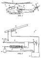
Figure 1 is a perspective view of an aircraft having a tactile cueing system according to the present invention. -
Figure 2 is a simplified schematic of the tactile cueing system for aircraft controls according to the present invention. -
Figure 3 is an exemplary configuration of the simplified representation of the tactile cueing system according to the present invention. -
Figure 4 is a detailed schematic of the tactile cueing system according to the present invention. -
Figure 5 is a table of flight data parameters used by the tactile cueing system according to the present invention. - The method and apparatus of the present invention uses tactile feedback to cue a pilot of impending exceedance of one or more operational parameters of an aircraft. The present invention enables the pilot to maintain "eyes-out-the-window" references during high-workload maneuvering tasks. Although the present invention is described with regard to a helicopter and HUMS parameters, it should be understood that the present invention is not limited to such applications, but may be used as an independent system on any rotorcraft or other aircraft, with or without a HUMS.
- As with any helicopter limit cueing system, the cueing required for closed-loop torque management must be timely and unambiguous. Simply introducing a soft-stop at the static collective position where an exceedance is first expected to occur is insufficient due to the false relief cues that may result. For example, if the collective is lowered to relieve the force cue, the aircraft could still be in an exceedance condition due to the application of other control inputs. In other situations, the cueing must be able to adapt to airspeed dependent limits on torque. Additional requirements for helicopter limit cueing systems flow down from safety, certification, performance, and cost and weight considerations, as follows: (1) the soft-stop must not have a failure mode that a pilot cannot overcome with tolerable control forces; (2) the prediction algorithm must provide a suitable lead-time; (3) discontinuous torque limits must not cause discontinuous cueing forces; (4) system costs, including the cost of retrofitting existing aircraft, must be kept to a minimum; and (5) system reliability must be high.
- Although the present invention is described below with respect to engine torque management, it will be appreciated that the method and apparatus of the present invention may be used to manage other aircraft parameters, such as rotor speed and engine temperature, or any other aircraft operational parameter that requires limiting and/or reducing control inputs.
- Referring to
Figure 1 in the drawings, anaircraft 10 having atactile cueing system 11 according to the present invention is illustrated. Althoughaircraft 10 is shown as a helicopter, it will be appreciated thataircraft 10 may be a fixed wing aircraft, a tilt rotor aircraft, or any other rotorcraft, such as a tilt wing aircraft or a tail sitter aircraft.Aircraft 10 includes afuselage 12, a drive means 18, and amain rotor 14. Torque imparted tofuselage 12 bymain rotor 14 is counter-acted by atail rotor assembly 16 mounted on atail portion 22 offuselage 12.Main rotor 14 andtail rotor assembly 16 are powered by drive means 18 under the control of a pilot in acockpit 20. - Referring now to
Figure 2 in the drawings, the preferred embodiment oftactile cueing system 11 is illustrated in a simplified schematic.Tactile cueing system 11 includes a forcegradient spring cartridge 13 placed in parallel with an existingcontrol linkage 15. One end ofspring cartridge 13 is coupled to existingcontrol linkage 15, and the other end ofspring cartridge 13 is coupled to anactuator arm 17 of anelectric stepper motor 19.Control linkage 15 is coupled to a collective 21 via a mixinglever 23. A switching means, ormicroswitch 25, is operably associated withspring cartridge 13, preferably by being disposed in-line withspring cartridge 13, to prevent inadvertent motion of collective 21 when the predicted torque drops below the limit torque andstepper motor 19 is ready to return to a free-wheeling mode. Aposition transducer 27 is operably associated withcontrol linkage 15 to provide position data forcontrol linkage 15. In addition, astick shaker 29 may be optionally attached to collective 21 to provide an additional tactile cue. As is shown,stepper motor 19,microswitch 25,position transducer 27, and stickshaker 29 are all coupled to asystem computer 31. - Referring now to
Figure 3 in the drawings, one exemplary configuration of the simplified representation oftactile cueing system 11 ofFigure 2 is illustrated. In the preferred embodiment,spring cartridge 13,control linkage 15,stepper motor 19, mixinglever 23, andmicroswitch 25 are disposed beneath the cabin floor ofaircraft 10. - Referring now to
Figure 4 in the drawings,tactile cueing system 11 is shown in a more detailed schematic.Figure 4 illustrates the inter-relation oftactile cueing system 11 to other control systems ofaircraft 10.Tactile cueing system 11 is controlled by a collective cueing processor (CCP) 51 that is powered byaircraft 10. Ifaircraft 10 includes a HUMS, it is preferred that the central processing unit (CPU) from the HUMS be used to perform the processing functions ofCCP 51. This is the configuration illustrated inFigure 4 . In such applications,CCP 51 is preferably based on the HUMS Processor Module (HPM) available from Smiths Aerospace Electronic Systems. Ifaircraft 10 does not include a HUMS, thenCCP 51 may comprise a stand alone unit. In addition, the processing functions ofCCP 51 may be performed by aflight control computer 59, providedaircraft 10 includes such aflight control computer 59, and thatflight control computer 59 has sufficient computing capacity to perform the processing functions ofCCP 51. Of course, it will be appreciated thatCCP 51 may also be a stand alone unit in applications in whichaircraft 10 includes a HUMS. In the preferred embodiment, anadditional interface card 55 to drive the high-current cueing devices, such asstepper motor 19,stick shaker 29, and warninglights 53, is integrated intotactile cueing system 11. - The HPM is preferably a 603e PowerPC processor based system with serial and discrete input/output capability. As well as having specialized avionics interface devices, the HPM is also fitted with four universal asynchronous receiver/transmitter (UART) serial interfaces 57, over which the HPM receives data from aircraft
flight control computers 59. -
Interface card 55 is used to enableCCP 51 to generate discrete output signals to drive the cueing devices.Interface card 55 inverts the signals to ensure that if power is removed fromCCP 51,stepper motor 19 is allowed to free wheel,stick shaker 29 and the over-torque indicator are disabled, andfailure warning indicator 53 is illuminated. -
CCP 51 uses flight data information from a data acquisition system ofaircraft 10 to identify the aircraft flight condition and predict the torque level. When the torque is predicted to exceed the transmission limit, a cue is provided. The cue can be generated in a number of forms, including collective force cueing, a stick shaker, voice warning, or visual warning. - As the pilot operates collective 21,
control linkage 15 drives one end ofspring cartridge 13. Whenaircraft 10 is being operated within its envelope limits, the shaft ofstepper motor 19 is free to move in either direction as dictated by forces applied toactuator arm 17. The forces applied toactuator arm 17 are those transmitted byspring cartridge 13 and are due to the motion of collective 21. During such time, the actual and predicted values of engine torque are below the torque limit. However, if the maximum of either the predicted or actual engine torque exceeds a selected limit, thesystem computer 31 directs these activities. - First, an engage flag for
stepper motor 19 is set true, makingstepper motor 19 act like a magnetic brake. Thus, if the pilot continues pulling up on collective 21,microswitch 25 shows its true state indicating thatspring cartridge 13 is in tension.Spring cartridge 13 then supplies a resistive force consisting of a breakout force and an increasing force proportional to the amount of exceedance. Once the pilot pushes down on collective 21 releasing the spring tension,microswitch 25 changes to its false state causingstepper motor 19 to revert to free-wheeling mode, thereby removing any resistance to corrective action. When the engage flag changes to true, the current location of collective 21 is recorded and serves as an initial value for both the actual location and the commanded location of collective 21. - Second, a collective limit position (CLIP) is calculated. This calculation determines where collective 21 should be so that the torque will just equal the limit at the future time, referred to as the prediction horizon. The CLIP is measured relative to the current location of the collective position, so only a change or delta needs to be calculated. The calculation itself comes from the amount the torque exceeds the limit multiplied by the gain relating inches of collective stick to change in torque. The CLIP is then added to the commanded location for the collective step.
- Third, a step command is issued to
stepper motor 19. If the commanded location is below the actual location, a "down" step is issued. If the commanded location is above the actual location, an "up" step is issued. Coincident commanded and actual location issues a "zero" step.Stepper motor 19 then moves one end ofspring cartridge 13 accordingly. If the pilot maintains just the breakout force on collective 21,stepper motor 19 actually drives the pilot's hand to track exactly the torque limit. If the pilot maintains collective 21 in one position, he feels the force modulate according to the degree of exceedance. -
Stepper motor 19, coupled with thespring cartridge 13, applies the required cueing force. In normal operations, below the torque limit,stepper motor 19 is designed to free wheel andspring cartridge 13 does not apply force to collective 21. If a torque exceedance is predicted,stepper motor 19 is engaged and an immediate collective force cue is transmitted to the pilot. The force cue preferably consists of an 8-pound breakout force at the torque limit plus a 1.4 pound per inch force gradient. Because collective position for limit torque will vary with flight condition and maneuver requirements, the resulting position is a dynamic value that requires constant update. - Fourth, if the exceedance is greater than a selected additional increment above the limit,
stick shaker 29 is activated. - These four evaluations are repeated every computational frame. The exact logic for stepper motor engagement and direction involves a truth table that uses values of torque exceedance, current and previous stepper motor engagement, and state of the microswitch.
- As set forth above, an important aspect of the present invention is the fact that the corrective action by the pilot for torque exceedance, rotor droop, and exhaust gas temperature is to push collective 21 down. In order to cue against a limit exceedance on all of these parameters, the system need only determine if any exceedance exists individually. If so,
tactile cueing system 11 starts the cueing process, then calculates the CLIP for each parameter that is exceeding its limit, and uses the most conservative answer. - Finally, the limits are not constants, but are instead functions of airspeed and other parameters. For instance, the torque limit changes in step fashion at a certain speed, for example Vq . In order to prevent a sudden change in cueing force due to a sudden change in limit value, the limit value is slowly changed as a function of airspeed proximity to Vq, and the rate at which the airspeed approaches Vq .
-
Flight control computers 59 provide flight data to control software residing onCCP 51, which sends applicable tactile cues to the pilot. The control software uses current control positions and aircraft flight parameters fromflight control computers 59 to perform a neural network based prediction of future mast torque. A prediction using the collective rate is also possible to compensate for aggressive collective inputs.CCP 51 controls the engagement and position ofstepper motor 19. - In the preferred embodiment,
tactile cueing system 11 uses flight data available from a typical HUMS system to provide the required input for tactile cueing. A major cost driver for a typical FDR or HUMS installation involves the acquisition of flight data from the predominately analogue transducers found on civil rotorcraft, and the processors required to implement HUMS applications. This means that the addition oftactile cueing system 11 on an aircraft already equipped with HUMS can be achieved at minimum additional cost. - Referring now to
Figure 5 in the drawings, a table of flight data parameters is illustrated. Three separate polynomial neural networks (PNN) predict the torque simultaneously. These predictions are compared to the current torque, and a final weighted average for future torque is produced. The preferred PNNs were developed using the group method of data handling (GMDH) algorithm. A major feature of the GMDH algorithm is that it produces deterministic algebraic expressions suitable for meeting software certification requirements. Each PNN uses an independent set of flight data parameters fromaircraft 10. The parameters are preferably grouped into the following categories: airframe, engine and pilot. The algorithm package has been written such that a different set of PNNs can be used depending on the current aircraft flight condition. Two exemplary flight conditions are: (1) above 40 knots; and (2) below 40 knots. - As set forth above,
tactile cueing system 11 comprises a parameter prediction and a "soft-stop" tactile cue. The parameter prediction uses a computer, associated software, and sensors of control position, engine parameters, and rotor performance to predict a future value of certain parameters based upon current values. Any number of algorithms can be applied to the prediction problem, including, but not limited to, Kalman filtering, extended Kalman filtering, linear prediction, trending, multi-variable surface fits of measured data, simple analytical expressions, artificial neural networks, and fuzzy logic. Some of the sensors measure current values of air data, such as airspeed and rate of descent. Other sensors measure performance parameters, such as engine torque, exhaust gas temperature, and rotor speed. Still other sensors measure pilot inputs through control displacement and rate information. All of this sensed data is sent to the aircraft's flight control computers to prepare the data for analysis. - Based on the selected algorithm, the parameter prediction is made of a future value of the desired performance parameters. This predicted value is then passed to a soft-stop cueing algorithm. The soft-stop algorithm is a "floating ground" algorithm. This means that a fixed reference point for the position of
spring cartridge 13 is not necessary. By utilizing this floating ground algorithm, additional sensors to detect the positions of either side ofspring cartridge 13 are not necessary. This reduces the cost of the system and increases reliability by reducing complexity. The use ofstepper motor 19 combines braking capability and precise position control of the floating ground side ofspring cartridge 13 without the requirement of additional sensors. - The cueing algorithm functions as an inverse model. The maximum of the predicted torque and the measured torque is known as the test torque. The test torque is compared to the torque limit, which varies with flight condition. If the test torque rises above the torque limit, the motor engages, establishing the ground for
spring cartridge 13. The pilot will feel the breakout force, and an increasing gradient force with continued upward movement of collective 21. In flight, determination of the test torque value is an ongoing process, and commands to actuatestepper motor 19 are continuously computed in order to drive the cue to correspond with the limit collective position. If the pilot lowers collective 21, decreasing the torque,stepper motor 19 is disengaged and becomes freewheeling. The inertia ofstepper motor 19 is small enough that no appreciable inertial resistance to collective motion is detected. The control algorithm also adapts to discontinuous torque limits within the helicopter flight envelope, using a ramp that is a function of the proximity and rate of approach to the discontinuity. -
Tactile cueing system 11 results in significant advantages in terms of system airworthiness considerations. During normal operationtactile cueing system 11 is transparent to the pilot. In the event of an impending torque exceedance, the pilot can still apply any required collective input by pulling through the breakout and gradient force. This is a very intuitive reaction. The use ofstepper motor 19 makes the possibility of an actuator hard-over very improbable. In the event of a mechanical jam the pilot can still fly throughspring cartridge 13 without objectionable collective forces. - It is apparent that an invention with significant advantages has been described and illustrated. Although the present invention is shown in a limited number of forms, it is not limited to just these forms, but is amenable to various changes and modifications without departing from the spirit thereof.
Claims (20)
- A tactile cueing system (11) for an aircraft (10) having a control mechanism (15) comprising:an electronic stepper motor (19);a force gradient spring (13) coupled at one end to the stepper motor (19) and at the other end to the control mechanism (15) ;a cueing processor (51) coupled to the stepper motor (19) for controlling the stepper motor (19);wherein the stepper motor (19) and the spring (13) impart a tactile cue to the control mechanism (15) if the control mechanism (15) is moved into a position that causes or would cause the aircraft (10) to exceed an operational limit of at least one selected operational parameter; andcharacterized in comprising a switching means (25) operably associated with the spring (13) for preventing inadvertent movement of the control mechanism (15) when a predicted future value of the at least one selected operational parameter does not exceed the selected operational limit of the aircraft (10).
- The tactile cueing system according to claim 1, wherein the tactile cue is a resistive breakout force.
- The tactile cueing system according to claim 2, wherein the stepper motor (19) and spring (13) also impart a second tactile cue that is increased in proportion to the amount of exceedance beyond the onset of the breakout force.
- The tactile cueing system according to claim 1, wherein the tactile cue modulates according to the degree of exceedance.
- The tactile cueing system according to claim 1, further comprising:a means for sensing the actual values of each selected operational parameter of the aircraft (10); anda parameter prediction algorithm programmed into the cueing processor (51) for predicting future values of each selected operational parameter;a cueing algorithm programmed into the cueing processor (51) for comparing the actual values and the predicted future values of the operational parameters;wherein the tactile cue is generated by the stepper motor (19) and the spring (13) based in response to an output from the cueing algorithm.
- The tactile cueing system according to claim 5, wherein the cueing algorithm is a floating ground algorithm for which the actual absolute sensed position of either end of the spring (13) is not required.
- The tactile cueing system according to claim 5, wherein the parameter prediction algorithm calculates a future position of the control mechanism that correlates to a position that would cause the aircraft (10) to exceed the operational limit of any one of the selected operational parameters, the future position being measured relative to the actual position of the control mechanism.
- The tactile cueing system according to claim 5, wherein the parameter prediction algorithm includes at least one technique for estimating the future values of the operational parameters.
- The tactile cueing system according to claim 5, wherein the parameter prediction algorithm and the cueing algorithm run continuously and periodically update during operation of the aircraft (10).
- The tactile cueing system according to claim 1, wherein a single corrective movement of the control mechanism (15) prevents the aircraft (10) from exceeding the operational limits of all of the selected operational parameters.
- The tactile cueing system according to claim 1, wherein the selected operational parameters include engine torque, rotor droop, and exhaust gas temperature.
- The tactile cueing system according to claim 1, wherein the operational limits are functions of the selected operational parameters, other operational parameters, or a combination of some or all of the selected operational parameters and the other operational parameters.
- The tactile cueing system according to claim 1, further comprising:a position transducer (27) operably associated with the control mechanism (15) for providing data on the position of the control mechanism (15).
- The tactile cueing system according to claim 1, further comprising:a health and usage monitoring system;wherein the health and usage monitoring system is coupled to the cueing processor (51).
- The tactile cueing system according to claim 14, wherein the health and usage monitoring system performs the processing functions of the cueing processor (51).
- The tactile cueing system according to claim 1, further comprising:a flight control computer (59) for controlling the aircraft (10);wherein the flight control computer (59) is coupled to the cueing processor (51).
- The tactile cueing system according to claim 16, wherein the flight control computer (59) performs the processing functions of the cueing processor (51).
- The tactile cueing system according to claim 1, wherein the stepper motor (19) moves freely while the control mechanism (15) is operated within the operational limits of the aircraft (10).
- An aircraft comprising the tactile cueing system according to claim 1, further comprising:a fuselage (12) ;a drive means (18) carried by the fuselage (12);a control mechanism for controlling the aircraft (10)
- The aircraft according to claim 19, further comprising:a means for sensing the actual values of each selected operational parameter of the aircraft (10); anda means for predicting future values of each selected operational parameter;wherein the tactile cue is generated by the stepper motor (19) and the spring (13) based upon a comparison of the actual values and the predicted future values of the operational parameters.
Applications Claiming Priority (5)
| Application Number | Priority Date | Filing Date | Title |
|---|---|---|---|
| US36705902P | 2002-03-21 | 2002-03-21 | |
| US367059P | 2002-03-21 | ||
| US38516402P | 2002-05-31 | 2002-05-31 | |
| US385164P | 2002-05-31 | ||
| PCT/US2003/008998 WO2003081554A1 (en) | 2002-03-21 | 2003-03-21 | Method and apparatus for tactile cueing of aircraft controls |
Publications (3)
| Publication Number | Publication Date |
|---|---|
| EP1485892A1 EP1485892A1 (en) | 2004-12-15 |
| EP1485892A4 EP1485892A4 (en) | 2010-11-17 |
| EP1485892B1 true EP1485892B1 (en) | 2012-10-17 |
Family
ID=28457147
Family Applications (1)
| Application Number | Title | Priority Date | Filing Date |
|---|---|---|---|
| EP03745181A Expired - Lifetime EP1485892B1 (en) | 2002-03-21 | 2003-03-21 | Method and apparatus for tactile cueing of aircraft controls |
Country Status (6)
| Country | Link |
|---|---|
| US (1) | US7098811B2 (en) |
| EP (1) | EP1485892B1 (en) |
| AU (1) | AU2003225960A1 (en) |
| BR (1) | BR0308594A (en) |
| CA (1) | CA2478535C (en) |
| WO (1) | WO2003081554A1 (en) |
Cited By (2)
| Publication number | Priority date | Publication date | Assignee | Title |
|---|---|---|---|---|
| US11618585B2 (en) | 2019-10-10 | 2023-04-04 | Ge Aviation Systems Limited | Integrated system for improved vehicle maintenance and safety |
| EP3366574B1 (en) * | 2017-02-27 | 2024-09-11 | Textron Innovations Inc. | Reverse tactile cue for rotorcraft rotor overspeed protection |
Families Citing this family (30)
| Publication number | Priority date | Publication date | Assignee | Title |
|---|---|---|---|---|
| US7463956B2 (en) * | 2003-07-03 | 2008-12-09 | The Boeing Company | Constant vertical state maintaining cueing system |
| US7262712B2 (en) * | 2004-04-12 | 2007-08-28 | Safe Flight Instrument Corporation | Helicopter tactile exceedance warning system |
| US7187274B2 (en) * | 2004-08-03 | 2007-03-06 | Franklin D Clark | Vibrating device for the turn signals in motorized vehicles |
| US7126496B2 (en) * | 2004-09-30 | 2006-10-24 | Safe Flight Instrument Corporation | Tactile cueing system and method for aiding a helicopter pilot in making landings |
| US7658349B2 (en) | 2006-10-26 | 2010-02-09 | Honeywell International Inc. | Pilot flight control stick haptic feedback system and method |
| US8626363B2 (en) * | 2007-02-08 | 2014-01-07 | Bell Helicopter Textron Inc. | Aircraft feathering, flapping and rotor loads indicator |
| US8271151B2 (en) | 2008-03-31 | 2012-09-18 | Sikorsky Aircraft Corporation | Flight control system for rotary wing aircraft |
| US8025256B2 (en) * | 2008-04-25 | 2011-09-27 | The Boeing Company | Precision adjust split detent for a vehicle |
| US7784340B2 (en) * | 2008-08-04 | 2010-08-31 | Bell Helicopter Textron, Inc. | Force gradient using a non-contact proximity sensor |
| WO2010016829A1 (en) | 2008-08-04 | 2010-02-11 | Bell Helicopter Textron, Inc. | Force gradient using a non-contact proximity sensor |
| WO2010039386A2 (en) * | 2008-10-02 | 2010-04-08 | Carrier Corporation | Refrigerant system with adaptive hot gas reheat |
| JP5594996B2 (en) * | 2009-09-14 | 2014-09-24 | 三菱重工業株式会社 | Aircraft control system |
| FR2959837B1 (en) * | 2010-05-07 | 2012-05-04 | Eurocopter France | SIMPLIFIED FLIGHT CONTROL SYSTEM HAVING A DEBRASABLE FRICTION DEVICE |
| US9304516B2 (en) | 2011-01-14 | 2016-04-05 | Textron Innovations Inc. | Flight control laws for vertical flight path |
| US8594864B2 (en) | 2011-08-24 | 2013-11-26 | Sikorsky Aircraft Corporation | Torque based power limit cueing system and method |
| US9102400B2 (en) | 2011-10-21 | 2015-08-11 | Sikorsky Aircraft Corporation | Methods and systems for providing constant-feel, multi-axis tactile cues |
| US9193450B2 (en) | 2012-02-24 | 2015-11-24 | Bell Helicopter Textron Inc. | System and method for automation of rotorcraft entry into autorotation and maintenance of stabilized autorotation |
| US9026274B2 (en) | 2012-08-31 | 2015-05-05 | Sikorsky Aircraft Corporation | Method of controlling an electric propulsion system |
| US9352824B2 (en) * | 2014-01-23 | 2016-05-31 | Woodward Mpc, Inc. | Line replaceable, fly-by-wire control column and control wheel assemblies with a centrally connected line replaceable disconnect and autopilot assembly |
| US9886039B2 (en) * | 2014-02-17 | 2018-02-06 | Bell Helicopter Textron Inc. | System and method for avoiding inadvertant entry into an unsafe vertical descent speed region for rotorcraft |
| US20150307203A1 (en) * | 2014-04-23 | 2015-10-29 | Sikorsky Aircraft Corporation | Vertical axis soft landing control |
| FR3021627B1 (en) * | 2014-05-28 | 2016-06-10 | Airbus Helicopters | ALARM DEVICE FOR A TILT SIGNAL GYROVAN PILOT USING A "TRIM CYLINDER" CONNECTED TO A FLIGHT CONTROL MEMBER |
| WO2016039834A2 (en) * | 2014-08-29 | 2016-03-17 | Sikorsky Aircraft Corporation | Vector limiting of a rotor control volume |
| PL3069990T3 (en) | 2015-03-20 | 2017-06-30 | Airbus Helicopters Deutschland GmbH | An artificial force feel generating device for a vehicle control system of a vehicle and, in particular, of an aircraft |
| CN106184774B (en) * | 2015-04-29 | 2018-07-24 | 陕西飞机工业(集团)有限公司 | More gradient people induction devices and its design method |
| US9828108B2 (en) * | 2016-03-10 | 2017-11-28 | The Boeing Company | Automated flight throttle control |
| CN105947185B (en) * | 2016-06-02 | 2018-01-30 | 江西洪都航空工业集团有限责任公司 | A kind of spring-loaded mechanism of low-frictional force |
| US10474237B2 (en) * | 2017-07-25 | 2019-11-12 | Rolls-Royce Corporation | Haptic feedback for rotary wing aircraft |
| US11117653B2 (en) * | 2017-11-28 | 2021-09-14 | Textron Innovations Inc. | System and method for tactile cueing through rotorcraft pilot controls using variable friction and force gradient |
| FR3093320B1 (en) * | 2019-02-28 | 2021-01-29 | Airbus Helicopters | Haptic alert mechanism of an aircraft pilot and aircraft. |
Family Cites Families (10)
| Publication number | Priority date | Publication date | Assignee | Title |
|---|---|---|---|---|
| DE3382431D1 (en) * | 1982-01-22 | 1991-11-14 | British Aerospace | CONTROL UNIT. |
| DE3416969A1 (en) * | 1984-05-08 | 1985-11-14 | Messerschmitt-Bölkow-Blohm GmbH, 8012 Ottobrunn | METHOD AND DEVICE FOR STABILIZING THE TAX FORCE IN A TURNING PLANE |
| US4717098A (en) * | 1986-05-19 | 1988-01-05 | Mcdonnell Douglas Corporation | Actuator for a g-limiter override |
| US5076517A (en) * | 1989-08-14 | 1991-12-31 | United Technologies Corporation | Programmable, linear collective control system for a helicopter |
| US5062594A (en) * | 1990-11-29 | 1991-11-05 | The United States Of America As Represented By The Secretary Of The Air Force | Flight control system with tactile feedback |
| FR2766158B1 (en) * | 1997-07-18 | 1999-10-01 | Bonnans Sa | PROCEDURE AND DEVICE TO ASSIST THE CONTROL, BY THE PILOT, OF THE POWER LIMITATIONS OF THE TURBOMOTOR (S) AND / OR OF THE ROTOR SPEED OF THERMOPROPULATED HELICOPTERS |
| US5986582A (en) * | 1998-06-24 | 1999-11-16 | Safe Flight Instrument Corporation | Helicopter rotor/engine warning system |
| US6002349A (en) * | 1998-08-14 | 1999-12-14 | Safe Flight Instrument Corporation | Helicopter anti-torque limit warning device |
| US6695264B2 (en) * | 2000-05-16 | 2004-02-24 | Bell Helicopter Textron, Inc. | Power lever tactile cueing system |
| US6644600B1 (en) * | 2002-04-25 | 2003-11-11 | Rockwell Collins, Inc. | Method and system for providing manipulation restraining forces for a stick controller on an aircraft |
-
2003
- 2003-03-21 CA CA002478535A patent/CA2478535C/en not_active Expired - Lifetime
- 2003-03-21 AU AU2003225960A patent/AU2003225960A1/en not_active Abandoned
- 2003-03-21 EP EP03745181A patent/EP1485892B1/en not_active Expired - Lifetime
- 2003-03-21 BR BR0308594-5A patent/BR0308594A/en not_active Application Discontinuation
- 2003-03-21 WO PCT/US2003/008998 patent/WO2003081554A1/en not_active Ceased
- 2003-03-21 US US10/508,303 patent/US7098811B2/en not_active Expired - Lifetime
Cited By (2)
| Publication number | Priority date | Publication date | Assignee | Title |
|---|---|---|---|---|
| EP3366574B1 (en) * | 2017-02-27 | 2024-09-11 | Textron Innovations Inc. | Reverse tactile cue for rotorcraft rotor overspeed protection |
| US11618585B2 (en) | 2019-10-10 | 2023-04-04 | Ge Aviation Systems Limited | Integrated system for improved vehicle maintenance and safety |
Also Published As
| Publication number | Publication date |
|---|---|
| WO2003081554A1 (en) | 2003-10-02 |
| US7098811B2 (en) | 2006-08-29 |
| US20050151672A1 (en) | 2005-07-14 |
| EP1485892A1 (en) | 2004-12-15 |
| CA2478535C (en) | 2009-08-11 |
| CA2478535A1 (en) | 2003-10-02 |
| BR0308594A (en) | 2005-02-09 |
| AU2003225960A1 (en) | 2003-10-08 |
| EP1485892A4 (en) | 2010-11-17 |
Similar Documents
| Publication | Publication Date | Title |
|---|---|---|
| CA2478535C (en) | Method and apparatus for tactile cueing of aircraft controls | |
| US10577083B2 (en) | Method of controlling an artificial force feel generating device for generation of an artificial feeling of force on an inceptor of a vehicle control system | |
| US5489830A (en) | Control system with loadfeel and backdrive | |
| EP3620373B1 (en) | Stuck in detent monitors for collective and cyclic sticks | |
| CN110498054B (en) | Systems and methods for haptic cues using variable friction and force gradients | |
| US20030094539A1 (en) | Power lever tactile cueing system | |
| EP3366574B1 (en) | Reverse tactile cue for rotorcraft rotor overspeed protection | |
| EP3069990A1 (en) | An artificial force feel generating device for a vehicle control system of a vehicle and, in particular, of an aircraft | |
| EP3357809B1 (en) | System and method for stabilizing longitudinal acceleration of a rotorcraft | |
| US20060219840A1 (en) | Constant vertical state maintaining cueing system | |
| US10611492B2 (en) | System and method for tail rotor margin awareness | |
| EP3569497B1 (en) | System and method for tactile cueing through rotorcraft pilot controls using variable friction and force gradient | |
| EP3613671B1 (en) | Rotorcraft control mode transition smoothing | |
| EP3489134B1 (en) | System and method for pilot-in-control sensing in a rotorcraft | |
| EP3388335B1 (en) | Default in-detent vertical speed/altitude hold | |
| EP3627271B1 (en) | System and method for controlling rotorcraft | |
| EP1282554B1 (en) | Power lever tactile cueing system and method |
Legal Events
| Date | Code | Title | Description |
|---|---|---|---|
| PUAI | Public reference made under article 153(3) epc to a published international application that has entered the european phase |
Free format text: ORIGINAL CODE: 0009012 |
|
| 17P | Request for examination filed |
Effective date: 20040914 |
|
| AK | Designated contracting states |
Kind code of ref document: A1 Designated state(s): AT BE BG CH CY CZ DE DK EE ES FI FR GB GR HU IE IT LI LU MC NL PT RO SE SI SK TR |
|
| AX | Request for extension of the european patent |
Extension state: AL LT LV MK |
|
| A4 | Supplementary search report drawn up and despatched |
Effective date: 20101014 |
|
| RIC1 | Information provided on ipc code assigned before grant |
Ipc: B64C 27/56 20060101ALI20101008BHEP Ipc: G08B 23/00 20060101AFI20031009BHEP Ipc: B64C 13/46 20060101ALI20101008BHEP |
|
| 17Q | First examination report despatched |
Effective date: 20110406 |
|
| GRAP | Despatch of communication of intention to grant a patent |
Free format text: ORIGINAL CODE: EPIDOSNIGR1 |
|
| GRAS | Grant fee paid |
Free format text: ORIGINAL CODE: EPIDOSNIGR3 |
|
| GRAA | (expected) grant |
Free format text: ORIGINAL CODE: 0009210 |
|
| AK | Designated contracting states |
Kind code of ref document: B1 Designated state(s): DE FR GB IT |
|
| REG | Reference to a national code |
Ref country code: GB Ref legal event code: FG4D |
|
| REG | Reference to a national code |
Ref country code: DE Ref legal event code: R096 Ref document number: 60342373 Country of ref document: DE Effective date: 20121213 |
|
| PLBE | No opposition filed within time limit |
Free format text: ORIGINAL CODE: 0009261 |
|
| STAA | Information on the status of an ep patent application or granted ep patent |
Free format text: STATUS: NO OPPOSITION FILED WITHIN TIME LIMIT |
|
| 26N | No opposition filed |
Effective date: 20130718 |
|
| REG | Reference to a national code |
Ref country code: DE Ref legal event code: R097 Ref document number: 60342373 Country of ref document: DE Effective date: 20130718 |
|
| REG | Reference to a national code |
Ref country code: FR Ref legal event code: PLFP Year of fee payment: 14 |
|
| REG | Reference to a national code |
Ref country code: FR Ref legal event code: PLFP Year of fee payment: 15 |
|
| REG | Reference to a national code |
Ref country code: FR Ref legal event code: PLFP Year of fee payment: 16 |
|
| PGFP | Annual fee paid to national office [announced via postgrant information from national office to epo] |
Ref country code: GB Payment date: 20220328 Year of fee payment: 20 Ref country code: DE Payment date: 20220329 Year of fee payment: 20 |
|
| PGFP | Annual fee paid to national office [announced via postgrant information from national office to epo] |
Ref country code: IT Payment date: 20220322 Year of fee payment: 20 Ref country code: FR Payment date: 20220325 Year of fee payment: 20 |
|
| REG | Reference to a national code |
Ref country code: DE Ref legal event code: R071 Ref document number: 60342373 Country of ref document: DE |
|
| REG | Reference to a national code |
Ref country code: GB Ref legal event code: PE20 Expiry date: 20230320 |
|
| PG25 | Lapsed in a contracting state [announced via postgrant information from national office to epo] |
Ref country code: GB Free format text: LAPSE BECAUSE OF EXPIRATION OF PROTECTION Effective date: 20230320 |