EP1485872B1 - A morphological inspection method based on skeletonization - Google Patents
A morphological inspection method based on skeletonization Download PDFInfo
- Publication number
- EP1485872B1 EP1485872B1 EP03710191A EP03710191A EP1485872B1 EP 1485872 B1 EP1485872 B1 EP 1485872B1 EP 03710191 A EP03710191 A EP 03710191A EP 03710191 A EP03710191 A EP 03710191A EP 1485872 B1 EP1485872 B1 EP 1485872B1
- Authority
- EP
- European Patent Office
- Prior art keywords
- image
- defects
- color
- objects
- inspected
- Prior art date
- Legal status (The legal status is an assumption and is not a legal conclusion. Google has not performed a legal analysis and makes no representation as to the accuracy of the status listed.)
- Expired - Lifetime
Links
Images

Classifications
-
- G—PHYSICS
- G06—COMPUTING OR CALCULATING; COUNTING
- G06T—IMAGE DATA PROCESSING OR GENERATION, IN GENERAL
- G06T7/00—Image analysis
- G06T7/60—Analysis of geometric attributes
-
- G—PHYSICS
- G06—COMPUTING OR CALCULATING; COUNTING
- G06T—IMAGE DATA PROCESSING OR GENERATION, IN GENERAL
- G06T7/00—Image analysis
- G06T7/0002—Inspection of images, e.g. flaw detection
- G06T7/0004—Industrial image inspection
- G06T7/001—Industrial image inspection using an image reference approach
-
- G—PHYSICS
- G06—COMPUTING OR CALCULATING; COUNTING
- G06T—IMAGE DATA PROCESSING OR GENERATION, IN GENERAL
- G06T7/00—Image analysis
- G06T7/10—Segmentation; Edge detection
- G06T7/12—Edge-based segmentation
-
- G—PHYSICS
- G06—COMPUTING OR CALCULATING; COUNTING
- G06T—IMAGE DATA PROCESSING OR GENERATION, IN GENERAL
- G06T7/00—Image analysis
- G06T7/10—Segmentation; Edge detection
- G06T7/155—Segmentation; Edge detection involving morphological operators
-
- G—PHYSICS
- G06—COMPUTING OR CALCULATING; COUNTING
- G06T—IMAGE DATA PROCESSING OR GENERATION, IN GENERAL
- G06T2207/00—Indexing scheme for image analysis or image enhancement
- G06T2207/20—Special algorithmic details
- G06T2207/20036—Morphological image processing
- G06T2207/20044—Skeletonization; Medial axis transform
-
- G—PHYSICS
- G06—COMPUTING OR CALCULATING; COUNTING
- G06T—IMAGE DATA PROCESSING OR GENERATION, IN GENERAL
- G06T2207/00—Indexing scheme for image analysis or image enhancement
- G06T2207/30—Subject of image; Context of image processing
- G06T2207/30108—Industrial image inspection
- G06T2207/30148—Semiconductor; IC; Wafer
Definitions
- the present invention relates to a morphological tracking method. More specifically, the present invention relates to an inspection method that is useful in automatic inspection.
- Defects in the form of structural flaws, process residues, and external contamination occur during the production of objects such as Printed Circuit Boards, semiconductor wafers, artworks or reticles.
- Defects are typically detected by a class of instruments called defect scanners (or automatic optical inspection systems). Such instruments automatically scan the object's surfaces and detect morphological or design anomalies using a variety of techniques. The location of these anomalies with respect to the patterns on the object's surface is recorded. This information, or "defect map”, is stored in a computer file and sent to a defect review station.
- defect map to locate each defect, a human operator observes each defect under a microscope and characterizes each defect according to type (e.g., particle, pit, scratch, or contaminant). Information gained from this process is used to correct the source of defects, and thereby improve the efficiency and yield of the semiconductor production process.
- type e.g., particle, pit, scratch, or contaminant
- ADC Automatic Defect Characterization
- AOI Automatic Optical Inspection
- a skeleton comparison algorithm One of the well-known algorithms that is used by AOI systems is a skeleton comparison algorithm. This algorithm skeletonizes the objects of both image - the reference image and the inspected image - and compares the skeletons'junctions and the skeletons'ends in both of the two skeleton images. Skeletonization must be done in real time and in the inspection station. Moreover, the skeletonization process requires a lot of computing source. Consequently, the main disadvantage of these inspection systems is that they are complicated and expensive.
- the US-A-5 659 630 discloses an advanced manufacturing inspection system. Two streams of inspection and reference image travel through morphological operators in defect detection channels, and an image of the defect exists from each channel. A plurality of morphological functions can be performed including edge detection.
- the US-A-5 659 630 discloses a circuit that renders shorting defects.
- a doubly expanded image is ORed with a feature skeleton by first OR gates. The outputs of the first OR gates are input to a first logic block where the image is shrunk twelve times. The first logic block also receives a feature skeleton and provides outputs to second OR gates and first AND gates.
- the feature skeleton and a space skeleton have been previously produced either through morphic processing of the incoming reference image or as an adjunct stored image aligned with the reference image.
- the first AND gates also receive as inputs the space skeleton and provide outputs to a second logic block.
- the second OR gates also receive as inputs the image and provide outputs to second AND gates.
- the second AND gates also receive the space inputs and provide outputs to the second logic block.
- the second logic block grows the resulting image by twelve times and provides outputs to third AND gates, which also receive as inputs the image.
- the outputs of the third AND gates are an image of the detected defect.
- the present invention is a morphological inspection method based on a comparison of real images - a real reference image and a real inspected image of an inspected object.
- a morphological inspection method based on a comparison of a real reference binary image and a real inspected binary image of an inspected object as defined in claim 1.
- an inspection method is based on a comparison of real images, and comprises the steps of creating a reference mask that contains a first-color image and a second-color image, wherein the first-color image is obtained from skeletonization of the reference real image, thus generating a skeletons image and the second-color image is obtained from skeletonization of an inversion of the reference image, thus generating an edges-skeleton image; painting the inspected image in a third color and performing a logical AND-function using the first-color image and the third-color inspected image, thus generating a first-defects-image, then performing a logical AND-function using the second-color image and the third-color inspected image, thus generating a second-defects-image; and adding the first-defects-image and the second-defects-image, thus generating a defects-image or defects-map.
- At least one region of interest may be defined, according to inspection criteria, in the reference image and in the inversion of the reference image - wherein objects outside said at least one region of interest are ignorable - and each of the skeletonizations ignores the ignorable objects.
- skeletons of the first-color image and the second-color image may be trimmed in a way that ignorable defects are not appearing in the defects-image or the defects-map when performing the logical functions.
- the present invention is a morphological inspection method based on a comparison of real images.
- the method of the present invention defining regions of interest on a first-color image of the inspection reference object.
- the non-defined regions are ignorable.
- skeletonizing the image generates a first-color image.
- inverting the inspection reference object image and changing its color Defining regions of interest and skeletonizing the image, thus generating a second-color image of the objects edges.
- the first-color image contains skeletons of the objects of interest, while the second-color image contains edges of the objects of interest
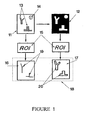
- FIG. 1 illustrates a mask preparation, according to the present invention.
- a first-color real image 11 is used as a reference for inspection.
- the first-color image 11 contains objects 13 for inspection and an ignorable object 14.
- a skeletons image (first color image) 16 contains skeletons 19 of the objects of interest and an edge-skeletons image (second color image) 17 contains skeletons 20 that are the edges of the objects of interest.
- the two images, the skeletons image 16 and the edge-skeletons image 17, are used as a reference mask 18.
- FIG. 2 illustrates the inspection process.
- the image 21 is the inspected image - obtained from an inspection scanner - contains interested images with a defect 23a (disconnection) in one object and another defect 23b (over-splay) in another object.
- the image contains an ignorable object 24.
- the inspected image 21 is compared with the reference mask 18 first, by performing logical function using the inspected image 21 and the skeletons image 16 of the reference mask 18 and second, by using the inspected image 21 with the edge-skeletons image 17 of the mask 18.
- generating a defects image 22 which contains the first detect (disconnection) 22a, which is recognized by the skeletons-image 16 and a second defect (over-splay) 22b, which is recognized by the edges-skeleton image 18. Since non-interested objects are not located in the regions of interest, the ignorable object 24 does not appear in the defects image 22.
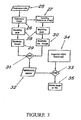
- Figure 3 illustrates a flow chart of the method when inspecting an object.
- Transferring reference data such as CAD data file or data achieved from a reference "golden” object
- a reference image 26 and inverting the image into an inverse reference image 27, each in different colors.
- Performing skeletonization of both images thus generating a skeletonized image 29 of the object's reference image and a skeletonized image of the inverted reference image 30.
- the defect detection process is done by performing logical function 33 using an inspected object real image 34 and the reference mask 32, thus generating a defects image 35 or defects file.
Landscapes
- Engineering & Computer Science (AREA)
- Physics & Mathematics (AREA)
- Computer Vision & Pattern Recognition (AREA)
- General Physics & Mathematics (AREA)
- Theoretical Computer Science (AREA)
- Quality & Reliability (AREA)
- Geometry (AREA)
- Image Processing (AREA)
- Investigating Materials By The Use Of Optical Means Adapted For Particular Applications (AREA)
- Image Analysis (AREA)
- Magnetic Resonance Imaging Apparatus (AREA)
- Analysing Materials By The Use Of Radiation (AREA)
- Length Measuring Devices By Optical Means (AREA)
- Testing Or Measuring Of Semiconductors Or The Like (AREA)
- Electrically Operated Instructional Devices (AREA)
- Crystals, And After-Treatments Of Crystals (AREA)
- Holo Graphy (AREA)
- Measurement And Recording Of Electrical Phenomena And Electrical Characteristics Of The Living Body (AREA)
Abstract
Description
- The present invention relates to a morphological tracking method. More specifically, the present invention relates to an inspection method that is useful in automatic inspection.
- Defects in the form of structural flaws, process residues, and external contamination occur during the production of objects such as Printed Circuit Boards, semiconductor wafers, artworks or reticles. Defects are typically detected by a class of instruments called defect scanners (or automatic optical inspection systems). Such instruments automatically scan the object's surfaces and detect morphological or design anomalies using a variety of techniques. The location of these anomalies with respect to the patterns on the object's surface is recorded. This information, or "defect map", is stored in a computer file and sent to a defect review station.
- Using the defect map to locate each defect, a human operator observes each defect under a microscope and characterizes each defect according to type (e.g., particle, pit, scratch, or contaminant). Information gained from this process is used to correct the source of defects, and thereby improve the efficiency and yield of the semiconductor production process. Unfortunately, people are relatively slow and are quickly fatigued by the highly-repetitive task of observing and characterizing defects.
- Methods of automatically characterizing defects, collectively known as Automatic Defect Characterization (ADC) or Automatic Optical Inspection (AOI) have been developed to overcome the disadvantages of manual defect characterization.
- One of the well-known algorithms that is used by AOI systems is a skeleton comparison algorithm. This algorithm skeletonizes the objects of both image - the reference image and the inspected image - and compares the skeletons'junctions and the skeletons'ends in both of the two skeleton images. Skeletonization must be done in real time and in the inspection station. Moreover, the skeletonization process requires a lot of computing source. Consequently, the main disadvantage of these inspection systems is that they are complicated and expensive.
- The US-A-5 659 630 discloses an advanced manufacturing inspection system. Two streams of inspection and reference image travel through morphological operators in defect detection channels, and an image of the defect exists from each channel. A plurality of morphological functions can be performed including edge detection. In particular, the US-A-5 659 630 discloses a circuit that renders shorting defects. A doubly expanded image is ORed with a feature skeleton by first OR gates. The outputs of the first OR gates are input to a first logic block where the image is shrunk twelve times. The first logic block also receives a feature skeleton and provides outputs to second OR gates and first AND gates. The feature skeleton and a space skeleton have been previously produced either through morphic processing of the incoming reference image or as an adjunct stored image aligned with the reference image. The first AND gates also receive as inputs the space skeleton and provide outputs to a second logic block. The second OR gates also receive as inputs the image and provide outputs to second AND gates. The second AND gates also receive the space inputs and provide outputs to the second logic block. The second logic block grows the resulting image by twelve times and provides outputs to third AND gates, which also receive as inputs the image. The outputs of the third AND gates are an image of the detected defect.
- It would be advantageous to have a method and a system, which once skeletonize objects of a reference image and compare this skeletonized image with a real image of the inspected object. This method reduces significantly the costs of the inspection scanners that intend to supply only a real image without real time skeletonization.
- Moreover, another computer wherein the processing time is not very critical can do the process.
- The present invention is a morphological inspection method based on a comparison of real images - a real reference image and a real inspected image of an inspected object.
- According to the teachings of the present invention there is provided a morphological inspection method based on a comparison of a real reference binary image and a real inspected binary image of an inspected object as defined in
claim 1. - According to the invention, an inspection method is based on a comparison of real images, and comprises the steps of creating a reference mask that contains a first-color image and a second-color image, wherein the first-color image is obtained from skeletonization of the reference real image, thus generating a skeletons image and the second-color image is obtained from skeletonization of an inversion of the reference image, thus generating an edges-skeleton image; painting the inspected image in a third color and performing a logical AND-function using the first-color image and the third-color inspected image, thus generating a first-defects-image, then performing a logical AND-function using the second-color image and the third-color inspected image, thus generating a second-defects-image; and adding the first-defects-image and the second-defects-image, thus generating a defects-image or defects-map.
- According to the inspection method of the present invention, at least one region of interest may be defined, according to inspection criteria, in the reference image and in the inversion of the reference image - wherein objects outside said at least one region of interest are ignorable - and each of the skeletonizations ignores the ignorable objects.
- According to the inspection method of the present invention, skeletons of the first-color image and the second-color image may be trimmed in a way that ignorable defects are not appearing in the defects-image or the defects-map when performing the logical functions.
- The invention is herein described, by way of example only, with reference to the accompanying drawings. With specific reference now to the drawings in detail, it is stressed that the particulars shown are by way of example and for purposes of illustrative discussion of the preferred embodiments of the present invention only, and are presented in the cause of providing what is believed to be the most useful and readily understood description of the principles and conceptual aspects of the invention. In this regard, no attempt is made to show structural details of the invention in more detail than is necessary for a fundamental understanding of the invention, the description taken with the drawings making apparent to those skilled in the art how the several forms of the invention may be embodied in practice.
- In the figures:
- Figure 1 illustrates a mask preparation, according to the present invention.
- Figure 2 illustrates the inspection process.
- Figure 3 illustrates a flow chart of the method.
- The present invention is a morphological inspection method based on a comparison of real images.
- According to the method of the present invention, defining regions of interest on a first-color image of the inspection reference object. The non-defined regions are ignorable. Then, skeletonizing the image generates a first-color image. In the next step, inverting the inspection reference object image and changing its color. Defining regions of interest and skeletonizing the image, thus generating a second-color image of the objects edges. The first-color image contains skeletons of the objects of interest, while the second-color image contains edges of the objects of interest
- In the inspection process, comparing a third-color image of the inspected object, with the first-color image. This comparison marks the defects of objects' shape. Then, comparing the third-color image of the inspected object, with the second-color image. This comparison marks the defects of objects' edges. By adding these two images, generating a defects image.
- The principles and operation of the method according to the present invention may be better understood with reference to the drawing and the accompanying description.
- Referring now to the drawing, Figure 1 illustrates a mask preparation, according to the present invention. A first-color
real image 11 is used as a reference for inspection. The first-color image 11 containsobjects 13 for inspection and anignorable object 14. Preferring aninverse image 12, which is the inverse of the first-color image 11, but in a second color. Identifying regions ofinterest 15 on both images 11&12 and performing skeletonization on both images while ignoring ignorable objects that are located out of the defined regions of interest. As a result, having generated two images, a skeletons image (first color image) 16 containsskeletons 19 of the objects of interest and an edge-skeletons image (second color image) 17 containsskeletons 20 that are the edges of the objects of interest. The two images, theskeletons image 16 and the edge-skeletons image 17, are used as areference mask 18. - Figure 2 illustrates the inspection process. The
image 21 is the inspected image - obtained from an inspection scanner - contains interested images with adefect 23a (disconnection) in one object and anotherdefect 23b (over-splay) in another object. In addition, the image contains anignorable object 24. The inspectedimage 21 is compared with thereference mask 18 first, by performing logical function using the inspectedimage 21 and theskeletons image 16 of thereference mask 18 and second, by using the inspectedimage 21 with the edge-skeletons image 17 of themask 18. As a result, generating adefects image 22, which contains the first detect (disconnection) 22a, which is recognized by the skeletons-image 16 and a second defect (over-splay) 22b, which is recognized by the edges-skeleton image 18. Since non-interested objects are not located in the regions of interest, theignorable object 24 does not appear in thedefects image 22. - Figure 3 illustrates a flow chart of the method when inspecting an object. Transferring reference data (such as CAD data file or data achieved from a reference "golden" object) 25 of an object into a
reference image 26 and inverting the image into an inverse reference image 27, each in different colors. Marking regions ofinterest 28 in both images. Performing skeletonization of both images, thus generating askeletonized image 29 of the object's reference image and a skeletonized image of theinverted reference image 30. Adding 31 both images into areference mask 32. The defect detection process is done by performinglogical function 33 using an inspected objectreal image 34 and thereference mask 32, thus generating adefects image 35 or defects file. - Although the invention has been described in conjunction with specific embodiments thereof, it is evident that many alternatives, modifications and variations will be apparent to those skilled in the art, accordingly, it is intended to embrace all such alternatives, modifications and variations that fall within the scope of the appended claims.
Claims (3)
- A morphological inspection method based on a comparison of a real reference binary image (11) and a real inspected binary image (21) of an inspected object, said method comprising:a) creating a reference mask (18), said reference mask (18) comprising a first-color image (16) and a second-color image (17) wherein:i) said first-color image (16) is obtained from skeletonization (29) of said reference image (11), thus generating a skeletons image (16) containing skeletons of objects of interest (13); andii) said second-color image (17) is obtained from skeletonization (30) of an inversion (12) of said reference image, thus generating an edges-skeletons image (17) containing skeletons that are the edges of the objects of interest (13);b) painting said inspected image in a third color and:i) performing (33) a logical AND-function marking defects of a shape of the objects of interest using said first-color image (16) and said third-color inspected image (21), thus generating a first-defects-image; andii) performing (33) a logical AND-function marking defects of edges of the interested objects using said second-color image (17) and said third-color inspected image (21), thus generating a second-defects-image; andc) adding said first-defects-image and said second-defects-image, thus generating an inspection-defects-image (22) or defects-map.
- The method of claim 1, wherein at least one region of interest (15) is defined (28), according to inspection criteria, in said reference image (11) and in said inversion (12) of said reference image, wherein objects outside said at least one region of interest (15) are ignorable, and each of said skeletonizations (29, 30) ignores said ignorable objects.
- The method of claim 1, wherein skeletons of said first-color image (16) and said second-color image (17) are trimmed in a way that ignorable defects neither appear in said first-defects-image nor in said second-defects-image or said defects-map (22) when performing said logical AND-function (33).
Applications Claiming Priority (3)
| Application Number | Priority Date | Filing Date | Title |
|---|---|---|---|
| IL14882802 | 2002-03-21 | ||
| IL148828A IL148828A (en) | 2002-03-21 | 2002-03-21 | Morphological tracking method |
| PCT/IL2003/000227 WO2003081531A1 (en) | 2002-03-21 | 2003-03-17 | A morphological inspection method based on skeletonization |
Publications (2)
| Publication Number | Publication Date |
|---|---|
| EP1485872A1 EP1485872A1 (en) | 2004-12-15 |
| EP1485872B1 true EP1485872B1 (en) | 2006-10-18 |
Family
ID=28053310
Family Applications (1)
| Application Number | Title | Priority Date | Filing Date |
|---|---|---|---|
| EP03710191A Expired - Lifetime EP1485872B1 (en) | 2002-03-21 | 2003-03-17 | A morphological inspection method based on skeletonization |
Country Status (9)
| Country | Link |
|---|---|
| US (1) | US7570799B2 (en) |
| EP (1) | EP1485872B1 (en) |
| JP (1) | JP4587438B2 (en) |
| AT (1) | ATE343183T1 (en) |
| AU (1) | AU2003214611A1 (en) |
| DE (1) | DE60309139T2 (en) |
| ES (1) | ES2275083T3 (en) |
| IL (1) | IL148828A (en) |
| WO (1) | WO2003081531A1 (en) |
Families Citing this family (10)
| Publication number | Priority date | Publication date | Assignee | Title |
|---|---|---|---|---|
| JP5006520B2 (en) * | 2005-03-22 | 2012-08-22 | 株式会社日立ハイテクノロジーズ | Defect observation apparatus and defect observation method using defect observation apparatus |
| ATE487995T1 (en) * | 2006-03-13 | 2010-11-15 | Given Imaging Ltd | CASCADE ANALYSIS FOR INTESTINAL CONTRACTION DETECTION |
| EP1997074B1 (en) * | 2006-03-13 | 2013-02-06 | Given Imaging Ltd. | Device, system and method for automatic detection of contractile activity in an image frame |
| DE102007043433B3 (en) * | 2007-03-24 | 2008-10-09 | Fraunhofer-Gesellschaft zur Förderung der angewandten Forschung e.V. | Apparatus and method for adapting a mask image |
| US20100046816A1 (en) * | 2008-08-19 | 2010-02-25 | Igual-Munoz Laura | Method for automatic classification of in vivo images |
| US9885671B2 (en) | 2014-06-09 | 2018-02-06 | Kla-Tencor Corporation | Miniaturized imaging apparatus for wafer edge |
| US9645097B2 (en) | 2014-06-20 | 2017-05-09 | Kla-Tencor Corporation | In-line wafer edge inspection, wafer pre-alignment, and wafer cleaning |
| JP2016058637A (en) * | 2014-09-11 | 2016-04-21 | 株式会社日立ハイテクノロジーズ | Overlay measurement method, apparatus, and display apparatus |
| CN112229853B (en) * | 2019-06-26 | 2022-11-29 | 长鑫存储技术有限公司 | Method and system for detecting droplet type defect |
| CN113822883B (en) * | 2021-11-22 | 2022-03-11 | 中导光电设备股份有限公司 | Wafer alignment method and system based on searching of straight edge of wafer |
Family Cites Families (6)
| Publication number | Priority date | Publication date | Assignee | Title |
|---|---|---|---|---|
| US5129009A (en) * | 1990-06-04 | 1992-07-07 | Motorola, Inc. | Method for automatic semiconductor wafer inspection |
| JPH07117498B2 (en) * | 1991-12-11 | 1995-12-18 | インターナショナル・ビジネス・マシーンズ・コーポレイション | Inspection system |
| JP3639079B2 (en) * | 1996-03-13 | 2005-04-13 | 富士通株式会社 | Pattern inspection method and inspection apparatus |
| JPH10269359A (en) * | 1997-03-25 | 1998-10-09 | Toppan Printing Co Ltd | Inspection method of printed matter and this apparatus |
| JPH1195408A (en) * | 1997-09-18 | 1999-04-09 | Toshiba Corp | Defect inspection method |
| JP2000147740A (en) * | 1998-11-06 | 2000-05-26 | Toppan Printing Co Ltd | Inspection device |
-
2002
- 2002-03-21 IL IL148828A patent/IL148828A/en not_active IP Right Cessation
-
2003
- 2003-03-17 JP JP2003579175A patent/JP4587438B2/en not_active Expired - Lifetime
- 2003-03-17 US US10/508,526 patent/US7570799B2/en not_active Expired - Lifetime
- 2003-03-17 ES ES03710191T patent/ES2275083T3/en not_active Expired - Lifetime
- 2003-03-17 AU AU2003214611A patent/AU2003214611A1/en not_active Abandoned
- 2003-03-17 DE DE60309139T patent/DE60309139T2/en not_active Expired - Lifetime
- 2003-03-17 AT AT03710191T patent/ATE343183T1/en not_active IP Right Cessation
- 2003-03-17 WO PCT/IL2003/000227 patent/WO2003081531A1/en not_active Ceased
- 2003-03-17 EP EP03710191A patent/EP1485872B1/en not_active Expired - Lifetime
Also Published As
| Publication number | Publication date |
|---|---|
| DE60309139D1 (en) | 2006-11-30 |
| ES2275083T3 (en) | 2007-06-01 |
| US20060233433A1 (en) | 2006-10-19 |
| IL148828A (en) | 2007-10-31 |
| IL148828A0 (en) | 2002-09-12 |
| EP1485872A1 (en) | 2004-12-15 |
| AU2003214611A1 (en) | 2003-10-08 |
| ATE343183T1 (en) | 2006-11-15 |
| JP2005521254A (en) | 2005-07-14 |
| DE60309139T2 (en) | 2007-08-30 |
| JP4587438B2 (en) | 2010-11-24 |
| US7570799B2 (en) | 2009-08-04 |
| WO2003081531A1 (en) | 2003-10-02 |
Similar Documents
| Publication | Publication Date | Title |
|---|---|---|
| CN115791822B (en) | Visual inspection algorithm and inspection system for wafer surface defects | |
| US5129009A (en) | Method for automatic semiconductor wafer inspection | |
| US6272236B1 (en) | Inspection technique of photomask | |
| KR100954703B1 (en) | Method and system for detecting defects | |
| JP4095860B2 (en) | Defect inspection method and apparatus | |
| US7155052B2 (en) | Method for pattern inspection | |
| US8089058B2 (en) | Method for establishing a wafer testing recipe | |
| US20020143483A1 (en) | Inspection system, inspection apparatus, inspection program, and production method of semiconductor devices | |
| US4778745A (en) | Defect detection method of semiconductor wafer patterns | |
| US7570799B2 (en) | Morphological inspection method based on skeletonization | |
| Dom et al. | The P300: A system for automatic patterned wafer inspection | |
| Zhang et al. | The development of an automatic post-sawing inspection system using computer vision techniques | |
| Bayro-Corrochano | Review of automated visual inspection 1983-1993, Part I: conventional approaches | |
| JPH02159681A (en) | Geometrical characteristic discrimination | |
| US20070055467A1 (en) | Workpiece inspection apparatus assisting device, workpiece inspection method and computer-readable recording media storing program therefor | |
| Breaux et al. | Automatic defect classification system for patterned semiconductor wafers | |
| CN117132797A (en) | An LCD display POLMARK positioning detection method and system | |
| JPH06129992A (en) | Inspection device for periodic pattern | |
| JP3753234B2 (en) | Defect detection method | |
| JPS61151410A (en) | Pattern defect detection and its apparatus | |
| JPH0441777B2 (en) | ||
| JP2676990B2 (en) | Wiring pattern inspection equipment | |
| Ben-Porath et al. | Advanced process development and control based on a fully automated SEM with ADC | |
| JPH0374855A (en) | Chip size detection method, chip pitch detection method, chip array data automatic creation method, and semiconductor substrate inspection method and device using the same | |
| JPS6135303A (en) | Pattern defect inspecting instrument |
Legal Events
| Date | Code | Title | Description |
|---|---|---|---|
| PUAI | Public reference made under article 153(3) epc to a published international application that has entered the european phase |
Free format text: ORIGINAL CODE: 0009012 |
|
| 17P | Request for examination filed |
Effective date: 20041020 |
|
| AK | Designated contracting states |
Kind code of ref document: A1 Designated state(s): AT BE BG CH CY CZ DE DK EE ES FI FR GB GR HU IE IT LI LU MC NL PT RO SE SI SK TR |
|
| AX | Request for extension of the european patent |
Extension state: AL LT LV MK |
|
| 17Q | First examination report despatched |
Effective date: 20050331 |
|
| GRAP | Despatch of communication of intention to grant a patent |
Free format text: ORIGINAL CODE: EPIDOSNIGR1 |
|
| GRAS | Grant fee paid |
Free format text: ORIGINAL CODE: EPIDOSNIGR3 |
|
| GRAA | (expected) grant |
Free format text: ORIGINAL CODE: 0009210 |
|
| AK | Designated contracting states |
Kind code of ref document: B1 Designated state(s): AT BE BG CH CY CZ DE DK EE ES FI FR GB GR HU IE IT LI LU MC NL PT RO SE SI SK TR |
|
| PG25 | Lapsed in a contracting state [announced via postgrant information from national office to epo] |
Ref country code: SK Free format text: LAPSE BECAUSE OF FAILURE TO SUBMIT A TRANSLATION OF THE DESCRIPTION OR TO PAY THE FEE WITHIN THE PRESCRIBED TIME-LIMIT Effective date: 20061018 Ref country code: CZ Free format text: LAPSE BECAUSE OF FAILURE TO SUBMIT A TRANSLATION OF THE DESCRIPTION OR TO PAY THE FEE WITHIN THE PRESCRIBED TIME-LIMIT Effective date: 20061018 Ref country code: FI Free format text: LAPSE BECAUSE OF FAILURE TO SUBMIT A TRANSLATION OF THE DESCRIPTION OR TO PAY THE FEE WITHIN THE PRESCRIBED TIME-LIMIT Effective date: 20061018 Ref country code: LI Free format text: LAPSE BECAUSE OF FAILURE TO SUBMIT A TRANSLATION OF THE DESCRIPTION OR TO PAY THE FEE WITHIN THE PRESCRIBED TIME-LIMIT Effective date: 20061018 Ref country code: CH Free format text: LAPSE BECAUSE OF FAILURE TO SUBMIT A TRANSLATION OF THE DESCRIPTION OR TO PAY THE FEE WITHIN THE PRESCRIBED TIME-LIMIT Effective date: 20061018 Ref country code: RO Free format text: LAPSE BECAUSE OF FAILURE TO SUBMIT A TRANSLATION OF THE DESCRIPTION OR TO PAY THE FEE WITHIN THE PRESCRIBED TIME-LIMIT Effective date: 20061018 Ref country code: SI Free format text: LAPSE BECAUSE OF FAILURE TO SUBMIT A TRANSLATION OF THE DESCRIPTION OR TO PAY THE FEE WITHIN THE PRESCRIBED TIME-LIMIT Effective date: 20061018 |
|
| REG | Reference to a national code |
Ref country code: GB Ref legal event code: FG4D |
|
| REG | Reference to a national code |
Ref country code: CH Ref legal event code: EP Ref country code: IE Ref legal event code: FG4D |
|
| REF | Corresponds to: |
Ref document number: 60309139 Country of ref document: DE Date of ref document: 20061130 Kind code of ref document: P |
|
| PG25 | Lapsed in a contracting state [announced via postgrant information from national office to epo] |
Ref country code: BG Free format text: LAPSE BECAUSE OF FAILURE TO SUBMIT A TRANSLATION OF THE DESCRIPTION OR TO PAY THE FEE WITHIN THE PRESCRIBED TIME-LIMIT Effective date: 20070118 Ref country code: SE Free format text: LAPSE BECAUSE OF FAILURE TO SUBMIT A TRANSLATION OF THE DESCRIPTION OR TO PAY THE FEE WITHIN THE PRESCRIBED TIME-LIMIT Effective date: 20070118 Ref country code: DK Free format text: LAPSE BECAUSE OF FAILURE TO SUBMIT A TRANSLATION OF THE DESCRIPTION OR TO PAY THE FEE WITHIN THE PRESCRIBED TIME-LIMIT Effective date: 20070118 |
|
| PG25 | Lapsed in a contracting state [announced via postgrant information from national office to epo] |
Ref country code: PT Free format text: LAPSE BECAUSE OF FAILURE TO SUBMIT A TRANSLATION OF THE DESCRIPTION OR TO PAY THE FEE WITHIN THE PRESCRIBED TIME-LIMIT Effective date: 20070319 |
|
| ET | Fr: translation filed | ||
| REG | Reference to a national code |
Ref country code: CH Ref legal event code: PL |
|
| REG | Reference to a national code |
Ref country code: ES Ref legal event code: FG2A Ref document number: 2275083 Country of ref document: ES Kind code of ref document: T3 |
|
| PLBE | No opposition filed within time limit |
Free format text: ORIGINAL CODE: 0009261 |
|
| STAA | Information on the status of an ep patent application or granted ep patent |
Free format text: STATUS: NO OPPOSITION FILED WITHIN TIME LIMIT |
|
| 26N | No opposition filed |
Effective date: 20070719 |
|
| PG25 | Lapsed in a contracting state [announced via postgrant information from national office to epo] |
Ref country code: MC Free format text: LAPSE BECAUSE OF NON-PAYMENT OF DUE FEES Effective date: 20070331 |
|
| PG25 | Lapsed in a contracting state [announced via postgrant information from national office to epo] |
Ref country code: GR Free format text: LAPSE BECAUSE OF FAILURE TO SUBMIT A TRANSLATION OF THE DESCRIPTION OR TO PAY THE FEE WITHIN THE PRESCRIBED TIME-LIMIT Effective date: 20070119 |
|
| PGFP | Annual fee paid to national office [announced via postgrant information from national office to epo] |
Ref country code: ES Payment date: 20080723 Year of fee payment: 6 |
|
| PGFP | Annual fee paid to national office [announced via postgrant information from national office to epo] |
Ref country code: FR Payment date: 20080729 Year of fee payment: 6 Ref country code: IE Payment date: 20080729 Year of fee payment: 6 Ref country code: IT Payment date: 20080725 Year of fee payment: 6 Ref country code: NL Payment date: 20080722 Year of fee payment: 6 Ref country code: AT Payment date: 20080728 Year of fee payment: 6 |
|
| PGFP | Annual fee paid to national office [announced via postgrant information from national office to epo] |
Ref country code: GB Payment date: 20080723 Year of fee payment: 6 |
|
| PG25 | Lapsed in a contracting state [announced via postgrant information from national office to epo] |
Ref country code: EE Free format text: LAPSE BECAUSE OF FAILURE TO SUBMIT A TRANSLATION OF THE DESCRIPTION OR TO PAY THE FEE WITHIN THE PRESCRIBED TIME-LIMIT Effective date: 20061018 |
|
| PG25 | Lapsed in a contracting state [announced via postgrant information from national office to epo] |
Ref country code: LU Free format text: LAPSE BECAUSE OF NON-PAYMENT OF DUE FEES Effective date: 20070317 Ref country code: CY Free format text: LAPSE BECAUSE OF FAILURE TO SUBMIT A TRANSLATION OF THE DESCRIPTION OR TO PAY THE FEE WITHIN THE PRESCRIBED TIME-LIMIT Effective date: 20061018 |
|
| PG25 | Lapsed in a contracting state [announced via postgrant information from national office to epo] |
Ref country code: HU Free format text: LAPSE BECAUSE OF FAILURE TO SUBMIT A TRANSLATION OF THE DESCRIPTION OR TO PAY THE FEE WITHIN THE PRESCRIBED TIME-LIMIT Effective date: 20070419 Ref country code: TR Free format text: LAPSE BECAUSE OF FAILURE TO SUBMIT A TRANSLATION OF THE DESCRIPTION OR TO PAY THE FEE WITHIN THE PRESCRIBED TIME-LIMIT Effective date: 20061018 |
|
| PG25 | Lapsed in a contracting state [announced via postgrant information from national office to epo] |
Ref country code: AT Free format text: LAPSE BECAUSE OF NON-PAYMENT OF DUE FEES Effective date: 20090317 |
|
| GBPC | Gb: european patent ceased through non-payment of renewal fee |
Effective date: 20090317 |
|
| NLV4 | Nl: lapsed or anulled due to non-payment of the annual fee |
Effective date: 20091001 |
|
| REG | Reference to a national code |
Ref country code: FR Ref legal event code: ST Effective date: 20091130 |
|
| PG25 | Lapsed in a contracting state [announced via postgrant information from national office to epo] |
Ref country code: IE Free format text: LAPSE BECAUSE OF NON-PAYMENT OF DUE FEES Effective date: 20090317 |
|
| PG25 | Lapsed in a contracting state [announced via postgrant information from national office to epo] |
Ref country code: NL Free format text: LAPSE BECAUSE OF NON-PAYMENT OF DUE FEES Effective date: 20091001 |
|
| PG25 | Lapsed in a contracting state [announced via postgrant information from national office to epo] |
Ref country code: GB Free format text: LAPSE BECAUSE OF NON-PAYMENT OF DUE FEES Effective date: 20090317 Ref country code: FR Free format text: LAPSE BECAUSE OF NON-PAYMENT OF DUE FEES Effective date: 20091123 |
|
| REG | Reference to a national code |
Ref country code: ES Ref legal event code: FD2A Effective date: 20090318 |
|
| PG25 | Lapsed in a contracting state [announced via postgrant information from national office to epo] |
Ref country code: ES Free format text: LAPSE BECAUSE OF NON-PAYMENT OF DUE FEES Effective date: 20090318 |
|
| PG25 | Lapsed in a contracting state [announced via postgrant information from national office to epo] |
Ref country code: IT Free format text: LAPSE BECAUSE OF NON-PAYMENT OF DUE FEES Effective date: 20090317 |
|
| REG | Reference to a national code |
Ref country code: DE Ref legal event code: R082 Ref document number: 60309139 Country of ref document: DE Representative=s name: VERTRETERANGABEN UNKLAR, DE |
|
| PGFP | Annual fee paid to national office [announced via postgrant information from national office to epo] |
Ref country code: DE Payment date: 20130510 Year of fee payment: 11 |
|
| PGFP | Annual fee paid to national office [announced via postgrant information from national office to epo] |
Ref country code: BE Payment date: 20130516 Year of fee payment: 11 |
|
| REG | Reference to a national code |
Ref country code: DE Ref legal event code: R119 Ref document number: 60309139 Country of ref document: DE |
|
| REG | Reference to a national code |
Ref country code: DE Ref legal event code: R119 Ref document number: 60309139 Country of ref document: DE Effective date: 20141001 |
|
| PG25 | Lapsed in a contracting state [announced via postgrant information from national office to epo] |
Ref country code: DE Free format text: LAPSE BECAUSE OF NON-PAYMENT OF DUE FEES Effective date: 20141001 |
|
| PG25 | Lapsed in a contracting state [announced via postgrant information from national office to epo] |
Ref country code: BE Free format text: LAPSE BECAUSE OF NON-PAYMENT OF DUE FEES Effective date: 20140331 |