EP1484898A1 - Procédé de télécommunication entre un terminal local et un terminal central et système mettant en oeuvre le procédé - Google Patents
Procédé de télécommunication entre un terminal local et un terminal central et système mettant en oeuvre le procédé Download PDFInfo
- Publication number
- EP1484898A1 EP1484898A1 EP04291378A EP04291378A EP1484898A1 EP 1484898 A1 EP1484898 A1 EP 1484898A1 EP 04291378 A EP04291378 A EP 04291378A EP 04291378 A EP04291378 A EP 04291378A EP 1484898 A1 EP1484898 A1 EP 1484898A1
- Authority
- EP
- European Patent Office
- Prior art keywords
- terminal
- data
- central
- module
- station
- Prior art date
- Legal status (The legal status is an assumption and is not a legal conclusion. Google has not performed a legal analysis and makes no representation as to the accuracy of the status listed.)
- Withdrawn
Links
- 238000000034 method Methods 0.000 title claims abstract description 25
- 238000012546 transfer Methods 0.000 claims abstract description 24
- 230000004044 response Effects 0.000 claims description 17
- 230000005540 biological transmission Effects 0.000 claims description 14
- 238000003745 diagnosis Methods 0.000 claims description 10
- 238000012545 processing Methods 0.000 claims description 9
- 238000003860 storage Methods 0.000 claims description 4
- 238000005538 encapsulation Methods 0.000 claims description 3
- 238000002360 preparation method Methods 0.000 description 10
- 238000006243 chemical reaction Methods 0.000 description 5
- 238000004891 communication Methods 0.000 description 5
- 238000010586 diagram Methods 0.000 description 5
- 238000012360 testing method Methods 0.000 description 4
- 101150012579 ADSL gene Proteins 0.000 description 3
- 102100020775 Adenylosuccinate lyase Human genes 0.000 description 3
- 108700040193 Adenylosuccinate lyases Proteins 0.000 description 3
- 230000006870 function Effects 0.000 description 3
- 230000000903 blocking effect Effects 0.000 description 2
- 235000021183 entrée Nutrition 0.000 description 2
- 210000001503 joint Anatomy 0.000 description 2
- 230000002457 bidirectional effect Effects 0.000 description 1
- 238000013480 data collection Methods 0.000 description 1
- 238000013461 design Methods 0.000 description 1
- 230000009977 dual effect Effects 0.000 description 1
- 239000000284 extract Substances 0.000 description 1
- 230000010354 integration Effects 0.000 description 1
- 238000012423 maintenance Methods 0.000 description 1
- 238000007726 management method Methods 0.000 description 1
- 238000004519 manufacturing process Methods 0.000 description 1
- 239000000463 material Substances 0.000 description 1
- 230000002028 premature Effects 0.000 description 1
- 238000011084 recovery Methods 0.000 description 1
- 230000033764 rhythmic process Effects 0.000 description 1
- 230000001360 synchronised effect Effects 0.000 description 1
- 238000012384 transportation and delivery Methods 0.000 description 1
- 238000013024 troubleshooting Methods 0.000 description 1
- 238000011144 upstream manufacturing Methods 0.000 description 1
Images



Classifications
-
- H—ELECTRICITY
- H04—ELECTRIC COMMUNICATION TECHNIQUE
- H04L—TRANSMISSION OF DIGITAL INFORMATION, e.g. TELEGRAPHIC COMMUNICATION
- H04L67/00—Network arrangements or protocols for supporting network services or applications
- H04L67/01—Protocols
- H04L67/12—Protocols specially adapted for proprietary or special-purpose networking environments, e.g. medical networks, sensor networks, networks in vehicles or remote metering networks
- H04L67/125—Protocols specially adapted for proprietary or special-purpose networking environments, e.g. medical networks, sensor networks, networks in vehicles or remote metering networks involving control of end-device applications over a network
-
- H—ELECTRICITY
- H04—ELECTRIC COMMUNICATION TECHNIQUE
- H04L—TRANSMISSION OF DIGITAL INFORMATION, e.g. TELEGRAPHIC COMMUNICATION
- H04L69/00—Network arrangements, protocols or services independent of the application payload and not provided for in the other groups of this subclass
- H04L69/30—Definitions, standards or architectural aspects of layered protocol stacks
- H04L69/32—Architecture of open systems interconnection [OSI] 7-layer type protocol stacks, e.g. the interfaces between the data link level and the physical level
- H04L69/322—Intralayer communication protocols among peer entities or protocol data unit [PDU] definitions
- H04L69/329—Intralayer communication protocols among peer entities or protocol data unit [PDU] definitions in the application layer [OSI layer 7]
Definitions
- the invention relates to real-time digital data transfer. between terminals transmitting such data, on the one hand, and a central terminal for their centralized processing, on the other hand, transfer using a highly accessible telecommunications network.
- highly accessible network is meant a network of public telecommunications, such as the switched telephone network PSTN, using the Internet, for example via an ADSL link (Asymmetrical Digital Subscriber Line), or the ISDN network (Network Digital with Service Integration), or GPRS (General Packet Radio System).
- ADSL link Asymmetrical Digital Subscriber Line
- ISDN ISDN Network
- GPRS General Packet Radio System
- the real-time digital data discussed here is data collected during the course of a real time process and therefore of non-negligible duration.
- the invention more particularly finds its application for the transfer of data from computers on board motor vehicles, such as engine control units or control units passenger compartment, to diagnostic stations for the operation of these vehicles, for example data servers, specific to vehicles under diagnosis, including test and / or troubleshooting.
- computers on board motor vehicles such as engine control units or control units passenger compartment
- diagnostic stations for the operation of these vehicles, for example data servers, specific to vehicles under diagnosis, including test and / or troubleshooting.
- VCI serial line Vehicle Communication Interface
- any garage called upon to carry out diagnostic must be equipped with as many diagnostic stations and servers of associated databases that he must test for brands, different types and models.
- the plaintiff proposes, despite the difficulties set out, to completely deport local diagnostic stations to a centralized site, which then only has one diagnostic station and its associated database server for each brand, type, even each model of vehicle.
- the terminal which is closest to him sends him a busy signal identical to the busy signal from the other processing station.
- the receiving terminal in no response from the transmitting station, transmits to the receiving station of the fictitious responses from the transmitting station, delivered at the rate of transmission of the station's real-time data Issuer.
- These fictitious responses can for example be repetition of the last effective response from the transmitting station. This mode of realization respects the dates only imperfectly, but contributes also to avoid blockages of stations and computers.
- the data transmitted by the remote terminal come from an on-board computer motor vehicle, which determines specific characteristics in the configuration frame, and the data sent by the terminal central come from a specific server chosen from a set of servers by said terminal according to specific characteristics contained in the configuration frame.
- the central terminal transmits data comprising specific server diagnostic session initializations to the on-board computer, which responds to it, via the remote terminal, with real time data developed by him and processed by said server in offset real time.
- the invention also relates to a system for implementing the above method, comprising a central terminal connected to a processing and at least one local terminal connected to a computer delivering real-time data, characterized by the fact that the central terminals and local are connected by a public telecommunication network.
- the invention relates to a diagnostic aid system of operation of a motor vehicle implementing the method of the invention, comprising a computer delivering real-time data on a digital bus, the system comprising a diagnostic station that can be connected to the digital bus, characterized by the fact that the diagnostic station is remote on a central site and that real-time data is transmitted to it, via a telecommunications network, by a local terminal connected to said bus.
- the central site includes several diagnostic stations each compatible with a particular brand or type of vehicle and a central terminal comprising a selection module arranged for select the diagnostic station compatible with real-time data transmitted.
- the local and central terminals each have a configuration module arranged to send and receive a frame configuration physical, a microprocessor to configure said terminals, a logic module for encapsulating and decapsulating real-time data and encoding and decoding of transfer frames.
- the local or central terminal includes a memory for real-time data received from the network, a storage and a module for reading said data, and a module of dating real-time data to be sent over the network, dating readings attached thereto, and the reading module reading and transmitting locally the real-time data at the rate of the dating which their match.
- the telecommunication system 1 ' comprises a central terminal 9 connected to a processing station 5 by a 5 'digital link and at least one local terminal 8 connected to a computer 3 by another digital link 3 '.
- the two terminals are connected to a wired public telecommunications network 7 of the type PSTN, ISDN or ADSL, by interface means 30 (terminal 8) and 40 (terminal 9), typically ADSL modem, at 512 kbps, and pilots associates (more commonly known as Anglo-Saxon driver), arranged to use the two lowest layers (layers 1 and link 2) enabled by the OSI (Open System) model Interconnection), and add a TCP / IP stack for, with the addition of a communication security overlay such as PPP (Point to Point Protocol), use the Ethernet protocol in ATM here (Asynchronous Transfer Mode) via the Internet, ISDN broadband or a radio telecommunication network like GPRS, allowing sufficient flow.
- a communication security overlay such as PPP (Point to Point Protocol)
- PPP Point to Point Protocol
- the interface means 30 and 40 each supply, when they are in during use, internal memory 31 and 41 respectively channel busy, respectively, which indicates that the terminal is busy.
- the computer and the diagnostic stations also deliver signals of occupation, universally recognized
- terminals 8 and 9 can exchange data say real time, i.e. belonging to real time sequences of data collected during the course of a type process industrial.
- a real-time sequence is an uninterrupted sequence of data collected such as the data which constitute it and the deviations of time, or dating, separating the collection of each of these data are inseparable information to be processed simultaneously.
- the duration of a sequence is unspecified and independent of the protocols of telecommunications on the network 7.
- the terminals 8 and 9 receive this real-time data from the computer 3 or a diagnostic station 5 via buses or links 3 ' and 5 '.
- they also include link interface means digital 84 (terminal 8) and 92 (terminal 9), typically pilots (drivers) characteristics of the computer 3, i.e. compatible with the various computers 3 and stations 5 possible, therefore compatible with CAN, ISO channels (KWP2000, 9141-2), or J1850, DDLx, DDS.
- link interface means digital 84 (terminal 8) and 92 (terminal 9) typically pilots (drivers) characteristics of the computer 3, i.e. compatible with the various computers 3 and stations 5 possible, therefore compatible with CAN, ISO channels (KWP2000, 9141-2), or J1850, DDLx, DDS.
- Reading modules 88 and 98 can read and transmit locally real-time data, if necessary at the rate of the dates which correspond, to the pilot modules 84 and 92 respectively as it will be explained later.
- timer modules 87 and 97 are provided for transmitting waiting data to the computer 3 or to the treatment 5, to avoid interruption of treatment when a memory 31, 41 signals that one of the terminals 8, 9 is in a state busy.
- these waiting data can be and explained later in the description of how the system works, either a busy signal or fictitious data simulating a response, in this case the repetition of an effective previous response from the station furthest from Terminal 8 or 9, or both, depending on the situation.
- the diagnostic aid system 1 is a variant of the system 1 'seen previously. It is suitable for making a automotive diagnostic treatment, for example locally in a garage owner, assisted by a central processing station.
- the system 1 ' includes a computer 3, here on board the vehicle 2 to be diagnosed, delivering real time data on a bus digital 3 'CAN or ISO connected, via a socket diagnosis not shown, at a local terminal 8, and at least one diagnostic station 5 deported to a central site and linked to a base technical data 50 and to a terminal 9 also central.
- the two terminals 8 and 9 can be put in communication by the network telecommunications public 7 and exchange real-time data from the computer 3 and / or from the diagnostic station 5.
- the two terminals 8 and 9 include all the means and modules of the terminals of the system 1 'seen previously and in FIG. 2 and if there are represented, they are referenced by the same numbers.
- the local terminal 8 additionally includes a human-machine interface HMI 6 comprising a keyboard and possibly a screen (not shown) receiving its images from the diagnostic station 5 via the network 7 and connected to microprocessor 75.
- Terminal 8 must be compatible with any make or type of vehicle, it is equipped with a set of diagnostic sockets consequently, put in parallel on the external input 3 'of the means interface 84.
- the central site can group several stations 5, each compatible with a brand or type particular vehicle 2 all connected to the same central terminal 9 which then comprises, in addition to the means already exposed, a module for selection 10 to select compatible diagnostic station 5 with the real-time data transmitted by the computer 3 and as many digital link interface means 92 and diagnostic sockets on 5 'buses, compatible with diagnostic sockets on 3' buses, whether there has 5 diagnostic stations at the central site.
- the selection module includes dual switches 11 for transmission to the station selected and 12 for reception of signals transmitted by it.
- the central terminal 9 is then connected to the diagnostic station 5 selected by module 10 thanks to those of interface means 92 selected, and these means format the real time data received in the same format as that used by the computer 3 and conversely, so that everything happens as if the station central diagnostic unit was directly connected to the diagnostic socket on the vehicle, except that local terminal 8 and central terminal 9 include timing modules 87 and 97 which may differ, in particular, the sequences or real-time data of the duration of transmission via network 7, as will be seen below.
- the mechanic introduces IT technical information on the HMI 6 to initialize the communication between local 8 and central 9 terminals, such as the network address of the central site, the type of vehicle in the brand, etc .
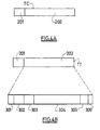
- ATM frames are exchanged here: TC configuration frames and TT transfer frames.
- a TC configuration frame as shown in Figure 4A, has the classic frame structure used in ATM networks, with a header 201 and a binary data stream 202.
- a TT transfer frame has externally the previous ATM structure, the binary data 202 being the result of the conversion of a data exchange frame CAN, ISO, ... on the VCI 3 'serial line, i.e. here again a SDLC (Synchronous Data Link Control) frame including conventionally a head separator 301, an address 302, a word of control 303, a binary data stream 304, the parity bits 305 and a queue separator 309.
- SDLC Serial Data Link Control
- the ATM frame encapsulates the frame SDLC, but not in full, the contents of header 201 which may include the address 302 and the control word 303, and the latter being, in this application, redundant, they can be deleted, freeing up space for 304 data that can be organized in an F format with increased capacity.
- module 75 receiving this information from the keyboard the HMI 6, then generates a TC configuration frame, constituted, as specified above, diagnostic request containing the IT information, establishes by the interface means 30 a connection physical 10 on the network between local 8 and central 9, which network transmits the TC configuration frame.
- the module configuration 86 waits for a response from the central terminal of the diagnostic station 9.
- the data transmitted by the local terminal 8 comes from the computer 3 on board the motor vehicle 2, which calculator determines specific characteristics introduced in the configuration frame.
- the interface means 40 of the central terminal 9 receive the frame of TC configuration, transmit it to its configuration module 96.
- the module 96 converts frame data, extracts information IT and, from this information, the vehicle type, controls the double switches 11 and 12 to select only one diagnostic station 5, that corresponding to the type of vehicle extracted, then makes a session request to the selected station diagnosis via the interface module 92.
- the station diagnostic 9 then creates a diagnostic session S for the type of vehicle, sends it by an R0 message the RS reference of this session and waits A.
- the data sent by the central terminal comes from the specific server (the selected diagnostic station) chosen among a set of servers by the terminal according to specific characteristics contained in the configuration frame.
- the configuration module 96 transmits the RS reference of the session S, the network address of the local terminal 8, the type and speed of transmission extracted from IT technical information, the logical format exchanges etc ... to the logic module 91, to the interface means 40, and to the preparation module 103, these modules memorizing the association of the RS reference to IT information.
- the microprocessor 105 of the terminal 9 then generates a frame of TC configuration in response to diagnostic request to establish the logical link which will be used later, but could also generate directly a TT transfer frame, constituted as specified above, if the IT information indicates that the local terminal 8 is already configured.
- This last configuration frame constitutes a message C0 emitted on the network by the interface means 40.
- a TT transfer frame replacing a TC frame is treated as an ordinary transfer frame to the difference except that, on reception, it is the configuration module 86 who is requested to configure the terminal, or update it software day, or both, as the case may be, in the same way that has been seen above.
- the configuration link performed can not only be used to complete the configuration of the local terminal 8 but also, for example, to download software for updating logic modules 81 and / or preparation 77, microprocessor 75, or other modules.
- the configuration module 86 transmits a transfer frame ordinary E0 containing a message P indicating to station 5 that the local terminal 8 and the computer 3 are ready, thus establishing a logical link between the computer 3 and the diagnostic station 5 selected, and ending the configuration phase ⁇ C.
- a deS diagnostic session phase immediately following this configuration phase, is initialized by a first request R1, T1, of real-time data, transmitted in a TT frame by the central terminal 9 to local terminal 8, which decapsulates, converts, and transmits to calculator 3.
- the local terminal 8 having received on its line interface 84, in return of the computer, the real-time data D1, converts them into the format F and can organize them into dated sequences, by the preparation module 77, and encapsulate them according to the structure of the TT frame by the module logic 81. It transmits the message obtained on the network by the means network interface 30 or 40.
- the central terminal 9 receives the frame T'1 by its means network interface 40, decapsulates data D1 by its logic module 91, reconverts them by the preparation module 103, in the format initial before conversion by module 77 of the other terminal. and the stores, by the storage module 102, in the memory buffer 101 or 89, available to session S of the station diagnosis 5 when the data is read, on action of the module timer 97, by the reading module 98 then transmitted by the line interface 92, the latter being selected by the module selection 10 as indicated above.
- timer modules 97 or 87 The operation of timer modules 97 or 87 will now be explained.
- module 97 of the terminal 9 sends it (a) a busy signal identical to the computer occupancy signal 3, or, according to a preferred mode of operation, with reference to FIG. 3B, the module 97 of the terminal 9 sends (b) to the reading module 98 a reading order in the memory buffer 101 of the last data stored there, D0 or D1 or D2, ... and send to station 5, as if it were the response to the last request R1 or R2 or R3 .... According to this preferred mode, the stored data D0, D1, D2, ...
- the period ⁇ t can be a data attached to the time data real or, to each real-time data can be added a dating t.
- the terminal 9 transmits to station 5 fictitious responses from the computer, delivered to the rate of transmission of real-time data from the computer.
- This last operating mode restores approximately the real-time data dating.
- the buffer memory 101 contains the data D1, D2, ..., Dn of a sequence of real-time data, closed by a delimiter F, necessary for a particular diagnosis, and to each datum of the sequence D1, D2, ..., Dn has been attached a date t1, t2, ..., tn of this data, performed by the preparation module 77.
- the reading module 98 receives from the storage module 102 a real-time data sequence end message (d) when the latter writes an indication F of this sequence in memory 101. From then on, at time t, it reads from memory 101 and transmits on the interface means of line 92 the data D1 at time t, the data D2 at time t + (t2 - t1), and so on until the data Dn at time t + (tn - t1).
Landscapes
- Engineering & Computer Science (AREA)
- Computer Networks & Wireless Communication (AREA)
- Signal Processing (AREA)
- Computer Security & Cryptography (AREA)
- Health & Medical Sciences (AREA)
- Computing Systems (AREA)
- General Health & Medical Sciences (AREA)
- Medical Informatics (AREA)
- Small-Scale Networks (AREA)
- Computer And Data Communications (AREA)
Abstract
Description
- la figure 1 est un schéma par blocs fonctionnels du système ;
- la figure 2 est un schéma par blocs fonctionnels d'une variante du système, convenant bien à une application au diagnostic des véhicules automobiles,
- les figures 3A et 3B sont des diagrammes montrant deux types d'échanges de données temps réel permettant d'éviter les blocages des stations de traitement ;
- les figures 4A et 4B sont des schémas montrant les structures d'une trame de configuration et d'une trame de transfert et
- la figure 5 est un schéma permettant d'expliquer le fonctionnement du rétablissement, en réception, du rythme de délivrance des données temps réel dans une séquence temps réel.
- un module de configuration 86 agencé pour émettre et recevoir une trame physique (couches OSI 1 et 2) de configuration comportant des informations sur les caractéristiques de la liaison à établir : type de véhicule, adresse, type et vitesse de transmission, description des caractéristiques de la trame de transfert des données temps réel (dont la fréquence de collecte) etc...
- un module 75 (qui pourrait être un microprocesseur) notamment pour autoconfigurer le terminal à émettre ou recevoir des trames de transfert une fois une trame de configuration émise,
- un module logique 81 d'encapsulation et de décapsulation des données temps réel et de codage et de décodage de trames de transfert,
- une mémoire tampon 89 des données temps réel reçues du réseau 7,
- un module 79 de mémorisation des données dans la mémoire tampon 89,
- un module de lecture 88 des données de la mémoire tampon 89,
- un module de préparation 77 des données à émettre sur le réseau, pour convertir le format des données temps réel du calculateur 3 en un format encapsulable, les datations relevées y étant jointes (si nécessaire) par ce même module, et des données reçues, pour convertir le format des données temps réel encapsulées en un format des données temps réel du calculateur 3, les datations relevées y étant extraites (si nécessaire) par ce même module,
- un module 87 de temporisation expliqué plus loin;
- un module de configuration 96 agencé pour émettre et recevoir une trame physique (couches OSI 1 et 2) de configuration comportant des informations sur les caractéristiques de la liaison à établir : type de station, adresse, type et vitesse de transmission, description des caractéristiques de la trame de transfert des données temps réel (dont la fréquence de collecte) etc...
- un module 105qui pourrait être un microprocesseur notamment pour autoconfigurer le terminal à émettre ou recevoir des trames de transfert une fois une trame de configuration reçue,
- un module logique 91 d'encapsulation et de décapsulation des données temps réel et de codage et de décodage de trames de transfert,
- une mémoire tampon 101 des données temps réel reçues du réseau 7,
- un module 102 de mémorisation des données dans la mémoire tampon 101,
- un module de lecture 98 des données de la mémoire tampon 101,
- un module de préparation 103 des données à émettre sur le réseau, pour convertir le format des données temps réel de la station de diagnostic 5 en un format encapsulable, les datations relevées y étant jointes (si nécessaire) par ce même module, et des données reçues, pour convertir le format des données temps réel encapsulées en un format des données temps réel de la station de diagnostic 5, les datations relevées y étant extraites (si nécessaire) par ce même module,
- un module 97 de temporisation expliqué plus loin.
- sur le terminal local 8, les moyens d'interface de liaison numériques 84 sont reliés en sortie au module de préparation 77 lui-même relié au module logique 81 en entrée-sortie des moyens interface réseau 30. Inversement, le module logique 81 est relié en sortie au module de préparation 77 pour conversion des données avant leur écriture par le module 79 dans la mémoire tampon 89, lue elle-même par le module de lecture 88 en entrée des moyens d'interface 84. Le module de temporisation 87 exploite la mémoire « occupé » 31 en sollicitant (a) les moyens interface 84 et (b) le module de lecture 88 pour répéter éventuellement des réponses antérieures du terminal central 9 mémorisées dans la mémoire tampon 89. L'ensemble est géré par le module 75 en fonction des informations recueillies par le module de configuration 86 ;
- sur le terminal central 9, les moyens d'interface de liaison numériques 92 sont reliés en sortie au module de préparation 103 lui-même relié au module logique 91 en entrée-sortie des moyens interface réseau 40. Inversement le module logique 91 est relié en sortie au module de préparation 103 pour conversion des données avant leur écriture par le module 102 dans la mémoire tampon 101, lue elle-même par le module de lecture 98 en entrée des moyens interface 92. Le module de temporisation 97 exploite la mémoire « occupé » 41 en sollicitant (a) les moyens interface 92 et (b) le module de lecture 98 pour répéter éventuellement des réponses antérieures du terminal local 8 mémorisées dans la mémoire tampon 101. L'ensemble est géré par le microprocesseur 105 en fonction des informations recueillies par le module de configuration 96.
Claims (19)
- Procédé de télécommunication entre un terminal numérique central (9) et au moins un terminal numérique distant (8), pour transférer, sur un réseau de transmission déterminé (7), des données délivrées en temps réel selon un format déterminé, procédé dans lequel :a) on établit une liaison physique sur le réseau (7) entre les terminaux central (9) et distant (8) et on transmet une trame de configuration TC,b) à partir de la trame de configuration, on configure les terminaux central (9) et distant (8),c) on établit une liaison logique sur le réseau entre les terminaux (9, 8) etd) on transfère les données selon une trame de transfert TT.
- Procédé selon la revendication 1, dans lequel, pour transférer les données,a) le terminal émetteur, central (9) ou distant (8), encapsule les données,b) transmet les données encapsulées,c) le terminal récepteur, distant (8) ou central (9), réceptionne (40) les données etd) décapsule (91) les données.
- Procédé selon l'une des revendications 1 et 2, dans lequel, pour éviter un blocage à l'une quelconque des stations de traitement, le terminal qui lui est le plus proche lui envoie (97) un signal d'occupation identique au signal d'occupation de l'autre station de traitement.
- Procédé selon l'une des revendications 1 à 3, dans lequel, en l'absence de réponses de la station émettrice, le terminal récepteur émet vers la station réceptrice des réponses fictives de la station émettrice, délivrées au rythme d'émission des données temps réel de la station émettrice.
- Procédé selon la revendication 4, dans lequel les réponses fictives sont la répétition de la dernière réponse effective de la station émettrice.
- Procédé selon l'une des revendications 2 à 5, dans lequel on encapsule les données avec des données de temps sur le terminal émetteur et on émet ces données après décapsulation, en sortie du terminal récepteur, à un rythme respectant les données de temps desdites données.
- Procédé selon l'une des revendications 1 à 6, caractérisé par le fait que les données émises par le terminal distant (8) sont issues d'un calculateur embarqué (3) d'un véhicule automobile, lequel détermine des caractéristiques spécifiques dans la trame de configuration.
- Procédé selon l'une des revendications 1 à 7, caractérisé par le fait que les données émises par le terminal central (9) sont issues d'un serveur spécifique choisi parmi un ensemble de serveurs par ledit terminal en fonction de caractéristiques spécifiques contenues dans la trame de configuration.
- Procédé selon la revendication 8, caractérisé par le fait que le terminal central (9) émet des données comportant des logiciels de mise à jour vers le terminal local (8).
- Système (1') pour la mise en oeuvre du procédé selon l'une des revendications 1 à 9, comportant un terminal central (9) relié à une station de traitement (5) et au moins un terminal local (8) relié à un calculateur (3) délivrant des données temps réel, caractérisé par le fait que les terminaux central (9) et local (8) sont reliés par un réseau de télécommunication public (7).
- Système (1") d'aide au diagnostic de fonctionnement d'un véhicule automobile (2) mettant en oeuvre le procédé d'une des revendications 1 à 9, comportant un calculateur (3) délivrant des données temps réel sur un bus numérique (3'), le système (1") comportant une station de diagnostic (5) pouvant être connecté sur le bus numérique (3') , caractérisé par le fait que la station de diagnostic (5) est déportée sur un site central et que les données temps réel lui sont transmises, via un réseau de télécommunication (7), par un terminal local (8) connecté sur ledit bus (3').
- Système selon la revendication 11, dans lequel le site central regroupe plusieurs stations de diagnostic (5) chacune compatible avec une marque ou un type particulier de véhicules (2) et un terminal central (9) comportant un module de sélection (10) agencé pour sélectionner la station de diagnostic (5) compatible avec les données temps réel transmises.
- Système selon l'une des revendication 10 et 12, dans lequel les terminaux local (8) et central (9) comportent chacun un module de configuration (86, 96) agencé pour émettre et recevoir une trame physique de configuration TC et un module (75, 105) pour configurer lesdits terminaux (8,9).
- Système selon l'une des revendications 10 à 13, dans lequel les terminaux local (8) et central (9) comportent chacun un module logique (81, 91) d'encapsulation et de décapsulation des données temps réel et de codage et de décodage de trames de transfert TT.
- Système selon l'une des revendications 10 à 14, dans lequel le terminal local (8) ou central (9) comporte une mémoire (89, 101) de stockage des données temps réel reçues du réseau (7), un module (79, 102) de mémorisation et un module de lecture (88, 98) desdites données, et un module de préparation (77, 103) des données temps réel à émettre sur le réseau, les datations relevées y étant jointes.
- Système selon la revendication 15, dans lequel le module de lecture (88, 98) lit et transmet localement les données temps réel au rythme des datations qui leur correspondent.
- Système selon l'une des revendications 11 à 16, dans lequel le terminal local (8) ou central (9) comporte au moins un pilote (84, 92), interface entre le terminal (8, 9) et le calculateur (3) ou la station de diagnostic (5) sélectionnée, formatant les données temps réel suivant le même format que celui utilisé par la station de diagnostic (5) ou par le calculateur (3).
- Système selon l'une des revendications 10 à 17, caractérisé par le fait que le terminal local (8) ou le terminal central (9) comporte un module de temporisation (87, 97) agencé pour émettre des données d'attente vers le calculateur (3) ou vers la station de diagnostic (5) pour éviter l'interruption du traitement ou de la session de diagnostic.
- Système selon l'une des revendications 10 à 18, caractérisé par le fait que le terminal local (8) ou le terminal central (9) comporte un module de temporisation (87, 97) agencé pour émettre un signal d'occupation vers le calculateur (3) ou vers la station de diagnostic (5) pour éviter l'interruption du traitement ou de la session de diagnostic quand une mémoire (31, 41) signale que l'un des terminaux (8, 9) est dans un état occupé
Applications Claiming Priority (2)
| Application Number | Priority Date | Filing Date | Title |
|---|---|---|---|
| FR0306797 | 2003-06-05 | ||
| FR0306797A FR2855925B1 (fr) | 2003-06-05 | 2003-06-05 | Procede de telecommunication entre un terminal local et un terminal central et systeme mettant en oeuvre le procede |
Publications (1)
| Publication Number | Publication Date |
|---|---|
| EP1484898A1 true EP1484898A1 (fr) | 2004-12-08 |
Family
ID=33155657
Family Applications (1)
| Application Number | Title | Priority Date | Filing Date |
|---|---|---|---|
| EP04291378A Withdrawn EP1484898A1 (fr) | 2003-06-05 | 2004-06-03 | Procédé de télécommunication entre un terminal local et un terminal central et système mettant en oeuvre le procédé |
Country Status (2)
| Country | Link |
|---|---|
| EP (1) | EP1484898A1 (fr) |
| FR (1) | FR2855925B1 (fr) |
Cited By (3)
| Publication number | Priority date | Publication date | Assignee | Title |
|---|---|---|---|---|
| CN101136764B (zh) * | 2006-08-31 | 2010-05-12 | 中兴通讯股份有限公司 | 用于在adsl终端远程管理中配置标识符的系统和方法 |
| DE102013202064A1 (de) * | 2013-02-08 | 2014-08-14 | Bayerische Motoren Werke Aktiengesellschaft | Verfahren und Vorrichtung zum Verbinden eines Diagnosegeräts mit einem Steuergerät in einem Kraftfahrzeug |
| CN105720689A (zh) * | 2016-03-22 | 2016-06-29 | 广州供电局有限公司 | 电力远动规约合并方法及电力远动规约合并器 |
Citations (5)
| Publication number | Priority date | Publication date | Assignee | Title |
|---|---|---|---|---|
| US6041042A (en) * | 1997-05-27 | 2000-03-21 | Cabletron Systems, Inc. | Remote port mirroring system and method thereof |
| EP1081670A2 (fr) * | 1999-08-31 | 2001-03-07 | Hitachi, Ltd. | Procédé et appareil de collecte d'information d'un véhicule |
| EP1087343A1 (fr) * | 1999-09-24 | 2001-03-28 | Renault | Procédé et dispositif de diagnostic véhicule à distance par reseau de communication |
| US20020150092A1 (en) * | 2001-04-17 | 2002-10-17 | Richard Bontempi | One-to-one communication |
| DE10145906A1 (de) * | 2001-09-18 | 2003-04-10 | Bosch Gmbh Robert | Verfahren zur Durchfühung einer Ferndiagnose bei einem Kraftfahrzeug, Fahrzeugdiagnosemodul und Servicecenter |
-
2003
- 2003-06-05 FR FR0306797A patent/FR2855925B1/fr not_active Expired - Fee Related
-
2004
- 2004-06-03 EP EP04291378A patent/EP1484898A1/fr not_active Withdrawn
Patent Citations (5)
| Publication number | Priority date | Publication date | Assignee | Title |
|---|---|---|---|---|
| US6041042A (en) * | 1997-05-27 | 2000-03-21 | Cabletron Systems, Inc. | Remote port mirroring system and method thereof |
| EP1081670A2 (fr) * | 1999-08-31 | 2001-03-07 | Hitachi, Ltd. | Procédé et appareil de collecte d'information d'un véhicule |
| EP1087343A1 (fr) * | 1999-09-24 | 2001-03-28 | Renault | Procédé et dispositif de diagnostic véhicule à distance par reseau de communication |
| US20020150092A1 (en) * | 2001-04-17 | 2002-10-17 | Richard Bontempi | One-to-one communication |
| DE10145906A1 (de) * | 2001-09-18 | 2003-04-10 | Bosch Gmbh Robert | Verfahren zur Durchfühung einer Ferndiagnose bei einem Kraftfahrzeug, Fahrzeugdiagnosemodul und Servicecenter |
Non-Patent Citations (1)
| Title |
|---|
| SCHULZRINNE H ET AL: "RFC 1889: RTP: A Transport Protocol for Real-Time Applications", NETWORK WORKING GROUP REQUEST FOR COMMENTS, XX, XX, January 1996 (1996-01-01), pages 1 - 38, XP002229836 * |
Cited By (6)
| Publication number | Priority date | Publication date | Assignee | Title |
|---|---|---|---|---|
| CN101136764B (zh) * | 2006-08-31 | 2010-05-12 | 中兴通讯股份有限公司 | 用于在adsl终端远程管理中配置标识符的系统和方法 |
| DE102013202064A1 (de) * | 2013-02-08 | 2014-08-14 | Bayerische Motoren Werke Aktiengesellschaft | Verfahren und Vorrichtung zum Verbinden eines Diagnosegeräts mit einem Steuergerät in einem Kraftfahrzeug |
| US10703309B2 (en) | 2013-02-08 | 2020-07-07 | Bayerische Motoren Werke Aktiengesellschaft | Method and device for connecting a diagnostic unit to a control unit in a motor vehicle |
| DE102013202064B4 (de) | 2013-02-08 | 2025-03-27 | Bayerische Motoren Werke Aktiengesellschaft | Verfahren und Vorrichtung zum Verbinden eines Diagnosegeräts mit einem Steuergerät in einem Kraftfahrzeug |
| CN105720689A (zh) * | 2016-03-22 | 2016-06-29 | 广州供电局有限公司 | 电力远动规约合并方法及电力远动规约合并器 |
| CN105720689B (zh) * | 2016-03-22 | 2018-06-08 | 广州供电局有限公司 | 电力远动规约合并方法及电力远动规约合并器 |
Also Published As
| Publication number | Publication date |
|---|---|
| FR2855925B1 (fr) | 2005-09-09 |
| FR2855925A1 (fr) | 2004-12-10 |
Similar Documents
| Publication | Publication Date | Title |
|---|---|---|
| EP0349371B1 (fr) | Système informatique à interconnexion centrale | |
| FR2553953A1 (fr) | Circuit en pont pour l'interconnexion de reseaux | |
| EP2320603A1 (fr) | Système de communication dans un aéronef | |
| CA2006831C (fr) | Systeme d'emission de trames hdlc sur canal de type mic, a circuit hdlc unique et memoire tampon de transposition | |
| EP3203445B1 (fr) | Systeme et procede d'identification automatique d'un modele de vehicule | |
| EP3771182B1 (fr) | Procédé pour détecter et identifier des equipements communiquant selon un protocole modbus et controleur de communication pour la mise en oeuvre d'un tel procédé | |
| EP1349078B1 (fr) | Installation, passerelle et procédé de téléchargement d'informations entre des équipements embarqués sur un aéronef et des moyens de chargement non-embarqués | |
| FR2812437A1 (fr) | Procede et dispositif de communication entre un equipement exterieur a un vehicule automobile et des calculateurs embarques | |
| FR2642245A1 (fr) | Systeme de reception et de traitement de trames hdlc transmises sur liaison mic multivoies a multiplexage temporel, notamment pour commutateur de donnees | |
| FR2712411A1 (fr) | Système de communication avec un réseau incluant un ensemble d'administration. | |
| EP1205849A1 (fr) | Dispositif d'adaptation programmable pour protocoles de communication | |
| EP1726124A1 (fr) | Systeme et procede de controle d'equipements a distance a l'aide de commandes at, dispositif, module de radiocommunication et programme correspondants | |
| EP1484898A1 (fr) | Procédé de télécommunication entre un terminal local et un terminal central et système mettant en oeuvre le procédé | |
| EP0179715B1 (fr) | Circuit interface de raccordement d'un équipement numérique à une liaison multiplexe temporelle | |
| FR2946164A1 (fr) | Procede de telechargement de donnees de grande taille vers un grand nombre de machines clientes en reseau a partir d'un serveur unique | |
| EP1636975A1 (fr) | Terminal et serveur pour synchroniser des donnees de contacts | |
| EP1160640B1 (fr) | Procédé de configuration d'un dispositif de régulation de chauffage à commande à distance | |
| WO2003085469A2 (fr) | Procede de diagnostic d'un equipement a controler, systeme de diagnostic, serveur intermediaire et module de communication associes | |
| EP1212879B1 (fr) | Procede et systeme de transmission d'une chaine de messages pour base de donnees | |
| EP0884223A1 (fr) | Dispositif et procédé de communication pour outil de diagnostic d'un véhicule automobile | |
| EP0666199B1 (fr) | Système électronique de véhicule automobile avec circuit d'interface entre deux bus différents | |
| BE1003811A3 (fr) | Systeme de test integre pour test de conformite de systemes de communication. | |
| FR2585909A1 (fr) | Procede de transmission de donnees par paquets a travers un reseau ou une chaine de transmission, et dispositif de mise en oeuvre | |
| FR3031822A1 (fr) | Telechargement de donnees sur un equipement distant | |
| FR2691029A1 (fr) | Procédé d'analyse à distance de données d'un protocole, terminal d'abonné spécialisé et dispositif d'analyse distant correspondant. |
Legal Events
| Date | Code | Title | Description |
|---|---|---|---|
| PUAI | Public reference made under article 153(3) epc to a published international application that has entered the european phase |
Free format text: ORIGINAL CODE: 0009012 |
|
| AK | Designated contracting states |
Kind code of ref document: A1 Designated state(s): AT BE BG CH CY CZ DE DK EE ES FI FR GB GR HU IE IT LI LU MC NL PL PT RO SE SI SK TR |
|
| AX | Request for extension of the european patent |
Extension state: AL HR LT LV MK |
|
| 17P | Request for examination filed |
Effective date: 20050602 |
|
| AKX | Designation fees paid |
Designated state(s): AT BE BG CH CY CZ DE DK EE ES FI FR GB GR HU IE IT LI LU MC NL PL PT RO SE SI SK TR |
|
| RAP1 | Party data changed (applicant data changed or rights of an application transferred) |
Owner name: JOHNSON CONTROLS AUTOMOTIVE ELECTRONICS |
|
| RAP1 | Party data changed (applicant data changed or rights of an application transferred) |
Owner name: SPX SERVICE SOLUTIONS FRANCE SARL |
|
| GRAP | Despatch of communication of intention to grant a patent |
Free format text: ORIGINAL CODE: EPIDOSNIGR1 |
|
| RIC1 | Information provided on ipc code assigned before grant |
Ipc: H04L 29/08 20060101AFI20130319BHEP |
|
| INTG | Intention to grant announced |
Effective date: 20130424 |
|
| STAA | Information on the status of an ep patent application or granted ep patent |
Free format text: STATUS: THE APPLICATION IS DEEMED TO BE WITHDRAWN |
|
| 18D | Application deemed to be withdrawn |
Effective date: 20130905 |