EP1484824A2 - Cable terminating apparatus and method - Google Patents
Cable terminating apparatus and method Download PDFInfo
- Publication number
- EP1484824A2 EP1484824A2 EP04253289A EP04253289A EP1484824A2 EP 1484824 A2 EP1484824 A2 EP 1484824A2 EP 04253289 A EP04253289 A EP 04253289A EP 04253289 A EP04253289 A EP 04253289A EP 1484824 A2 EP1484824 A2 EP 1484824A2
- Authority
- EP
- European Patent Office
- Prior art keywords
- cable
- connector
- wires
- manager
- cable manager
- Prior art date
- Legal status (The legal status is an assumption and is not a legal conclusion. Google has not performed a legal analysis and makes no representation as to the accuracy of the status listed.)
- Granted
Links
Images

Classifications
-
- H—ELECTRICITY
- H01—ELECTRIC ELEMENTS
- H01R—ELECTRICALLY-CONDUCTIVE CONNECTIONS; STRUCTURAL ASSOCIATIONS OF A PLURALITY OF MUTUALLY-INSULATED ELECTRICAL CONNECTING ELEMENTS; COUPLING DEVICES; CURRENT COLLECTORS
- H01R43/00—Apparatus or processes specially adapted for manufacturing, assembling, maintaining, or repairing of line connectors or current collectors or for joining electric conductors
- H01R43/01—Apparatus or processes specially adapted for manufacturing, assembling, maintaining, or repairing of line connectors or current collectors or for joining electric conductors for connecting unstripped conductors to contact members having insulation cutting edges
- H01R43/015—Handtools
-
- Y—GENERAL TAGGING OF NEW TECHNOLOGICAL DEVELOPMENTS; GENERAL TAGGING OF CROSS-SECTIONAL TECHNOLOGIES SPANNING OVER SEVERAL SECTIONS OF THE IPC; TECHNICAL SUBJECTS COVERED BY FORMER USPC CROSS-REFERENCE ART COLLECTIONS [XRACs] AND DIGESTS
- Y10—TECHNICAL SUBJECTS COVERED BY FORMER USPC
- Y10T—TECHNICAL SUBJECTS COVERED BY FORMER US CLASSIFICATION
- Y10T29/00—Metal working
- Y10T29/51—Plural diverse manufacturing apparatus including means for metal shaping or assembling
- Y10T29/5136—Separate tool stations for selective or successive operation on work
- Y10T29/5137—Separate tool stations for selective or successive operation on work including assembling or disassembling station
- Y10T29/5139—Separate tool stations for selective or successive operation on work including assembling or disassembling station and means to sever work prior to disassembling
- Y10T29/514—Separate tool stations for selective or successive operation on work including assembling or disassembling station and means to sever work prior to disassembling comprising means to strip insulation from wire
-
- Y—GENERAL TAGGING OF NEW TECHNOLOGICAL DEVELOPMENTS; GENERAL TAGGING OF CROSS-SECTIONAL TECHNOLOGIES SPANNING OVER SEVERAL SECTIONS OF THE IPC; TECHNICAL SUBJECTS COVERED BY FORMER USPC CROSS-REFERENCE ART COLLECTIONS [XRACs] AND DIGESTS
- Y10—TECHNICAL SUBJECTS COVERED BY FORMER USPC
- Y10T—TECHNICAL SUBJECTS COVERED BY FORMER US CLASSIFICATION
- Y10T29/00—Metal working
- Y10T29/51—Plural diverse manufacturing apparatus including means for metal shaping or assembling
- Y10T29/5147—Plural diverse manufacturing apparatus including means for metal shaping or assembling including composite tool
- Y10T29/5148—Plural diverse manufacturing apparatus including means for metal shaping or assembling including composite tool including severing means
- Y10T29/515—Plural diverse manufacturing apparatus including means for metal shaping or assembling including composite tool including severing means to trim electric component
- Y10T29/5151—Means comprising hand-manipulatable implement
-
- Y—GENERAL TAGGING OF NEW TECHNOLOGICAL DEVELOPMENTS; GENERAL TAGGING OF CROSS-SECTIONAL TECHNOLOGIES SPANNING OVER SEVERAL SECTIONS OF THE IPC; TECHNICAL SUBJECTS COVERED BY FORMER USPC CROSS-REFERENCE ART COLLECTIONS [XRACs] AND DIGESTS
- Y10—TECHNICAL SUBJECTS COVERED BY FORMER USPC
- Y10T—TECHNICAL SUBJECTS COVERED BY FORMER US CLASSIFICATION
- Y10T29/00—Metal working
- Y10T29/53—Means to assemble or disassemble
- Y10T29/5313—Means to assemble electrical device
-
- Y—GENERAL TAGGING OF NEW TECHNOLOGICAL DEVELOPMENTS; GENERAL TAGGING OF CROSS-SECTIONAL TECHNOLOGIES SPANNING OVER SEVERAL SECTIONS OF THE IPC; TECHNICAL SUBJECTS COVERED BY FORMER USPC CROSS-REFERENCE ART COLLECTIONS [XRACs] AND DIGESTS
- Y10—TECHNICAL SUBJECTS COVERED BY FORMER USPC
- Y10T—TECHNICAL SUBJECTS COVERED BY FORMER US CLASSIFICATION
- Y10T29/00—Metal working
- Y10T29/53—Means to assemble or disassemble
- Y10T29/5313—Means to assemble electrical device
- Y10T29/532—Conductor
- Y10T29/53209—Terminal or connector
-
- Y—GENERAL TAGGING OF NEW TECHNOLOGICAL DEVELOPMENTS; GENERAL TAGGING OF CROSS-SECTIONAL TECHNOLOGIES SPANNING OVER SEVERAL SECTIONS OF THE IPC; TECHNICAL SUBJECTS COVERED BY FORMER USPC CROSS-REFERENCE ART COLLECTIONS [XRACs] AND DIGESTS
- Y10—TECHNICAL SUBJECTS COVERED BY FORMER USPC
- Y10T—TECHNICAL SUBJECTS COVERED BY FORMER US CLASSIFICATION
- Y10T29/00—Metal working
- Y10T29/53—Means to assemble or disassemble
- Y10T29/5313—Means to assemble electrical device
- Y10T29/532—Conductor
- Y10T29/53209—Terminal or connector
- Y10T29/53213—Assembled to wire-type conductor
-
- Y—GENERAL TAGGING OF NEW TECHNOLOGICAL DEVELOPMENTS; GENERAL TAGGING OF CROSS-SECTIONAL TECHNOLOGIES SPANNING OVER SEVERAL SECTIONS OF THE IPC; TECHNICAL SUBJECTS COVERED BY FORMER USPC CROSS-REFERENCE ART COLLECTIONS [XRACs] AND DIGESTS
- Y10—TECHNICAL SUBJECTS COVERED BY FORMER USPC
- Y10T—TECHNICAL SUBJECTS COVERED BY FORMER US CLASSIFICATION
- Y10T29/00—Metal working
- Y10T29/53—Means to assemble or disassemble
- Y10T29/5313—Means to assemble electrical device
- Y10T29/532—Conductor
- Y10T29/53209—Terminal or connector
- Y10T29/53213—Assembled to wire-type conductor
- Y10T29/53217—Means to simultaneously assemble multiple, independent conductors to terminal
-
- Y—GENERAL TAGGING OF NEW TECHNOLOGICAL DEVELOPMENTS; GENERAL TAGGING OF CROSS-SECTIONAL TECHNOLOGIES SPANNING OVER SEVERAL SECTIONS OF THE IPC; TECHNICAL SUBJECTS COVERED BY FORMER USPC CROSS-REFERENCE ART COLLECTIONS [XRACs] AND DIGESTS
- Y10—TECHNICAL SUBJECTS COVERED BY FORMER USPC
- Y10T—TECHNICAL SUBJECTS COVERED BY FORMER US CLASSIFICATION
- Y10T29/00—Metal working
- Y10T29/53—Means to assemble or disassemble
- Y10T29/5313—Means to assemble electrical device
- Y10T29/532—Conductor
- Y10T29/53209—Terminal or connector
- Y10T29/53213—Assembled to wire-type conductor
- Y10T29/53222—Means comprising hand-manipulatable implement
-
- Y—GENERAL TAGGING OF NEW TECHNOLOGICAL DEVELOPMENTS; GENERAL TAGGING OF CROSS-SECTIONAL TECHNOLOGIES SPANNING OVER SEVERAL SECTIONS OF THE IPC; TECHNICAL SUBJECTS COVERED BY FORMER USPC CROSS-REFERENCE ART COLLECTIONS [XRACs] AND DIGESTS
- Y10—TECHNICAL SUBJECTS COVERED BY FORMER USPC
- Y10T—TECHNICAL SUBJECTS COVERED BY FORMER US CLASSIFICATION
- Y10T29/00—Metal working
- Y10T29/53—Means to assemble or disassemble
- Y10T29/5313—Means to assemble electrical device
- Y10T29/532—Conductor
- Y10T29/53243—Multiple, independent conductors
-
- Y—GENERAL TAGGING OF NEW TECHNOLOGICAL DEVELOPMENTS; GENERAL TAGGING OF CROSS-SECTIONAL TECHNOLOGIES SPANNING OVER SEVERAL SECTIONS OF THE IPC; TECHNICAL SUBJECTS COVERED BY FORMER USPC CROSS-REFERENCE ART COLLECTIONS [XRACs] AND DIGESTS
- Y10—TECHNICAL SUBJECTS COVERED BY FORMER USPC
- Y10T—TECHNICAL SUBJECTS COVERED BY FORMER US CLASSIFICATION
- Y10T29/00—Metal working
- Y10T29/53—Means to assemble or disassemble
- Y10T29/5313—Means to assemble electrical device
- Y10T29/53257—Means comprising hand-manipulatable implement
-
- Y—GENERAL TAGGING OF NEW TECHNOLOGICAL DEVELOPMENTS; GENERAL TAGGING OF CROSS-SECTIONAL TECHNOLOGIES SPANNING OVER SEVERAL SECTIONS OF THE IPC; TECHNICAL SUBJECTS COVERED BY FORMER USPC CROSS-REFERENCE ART COLLECTIONS [XRACs] AND DIGESTS
- Y10—TECHNICAL SUBJECTS COVERED BY FORMER USPC
- Y10T—TECHNICAL SUBJECTS COVERED BY FORMER US CLASSIFICATION
- Y10T29/00—Metal working
- Y10T29/53—Means to assemble or disassemble
- Y10T29/53274—Means to disassemble electrical device
- Y10T29/53283—Means comprising hand-manipulatable implement
Definitions
- the present invention relates to apparatus for terminating an electrical cable with a connector and methods of performing such a termination.
- Insulation displacement connection (IDC) cable termination where the cable contains a plurality of wires, with a connector containing a plurality of terminals, can be difficult to perform, particularly if the cable contains a number of small diameter wires such as the type typically used for telecommunications applications.
- IDC Insulation displacement connection
- Tools for such termination in the prior art typically are impact tools that require inserting wires one at a time into connector terminals, or terminate a number of wires at once.
- One wire at a time termination is a time consuming operation, and multiple wire termination may cause operator discomfort, because of the stress imposed by impact on those wires.
- connectors often break, a field replacement operation is often necessary, complicating the termination efforts.
- Termination may often also require cutting and/or stripping the wires and/or cable.
- Using prior art tools to perform the cutting may leave less than a flush cut, leaving wire ends exposed which may touch a shielding or electrically conductive member.
- the present invention provides apparatus and methods for positioning a plurality of wires of a cable relative to each other and terminating the cable with a connector.
- Embodiments comprise a cable manager (support means) for positioning wires of the cable in a fixed spaced relationship relative to each other and a guide means for engaging a complementary surface of the connector to guide terminals of the connector into electrically contacting relationship with the wires.
- a method of terminating a cable having a plurality of wires with a connector having a plurality of terminals comprising the steps of:
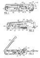
- Figure 1 shows a preferred embodiment.
- Figure 2 shows a view of the embodiment of Figure 1.
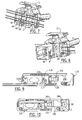
- Figure 3 shows a preferred embodiment.
- Figure 4 shows a view of the embodiment of Figure 3.
- Figure 5 shows another view of the embodiment of Figure 4.
- Figure 6 shows another view of the embodiment of Figure 4.
- Figure 7 shows another view of the embodiment of Figure 4.
- Figure 8 shows another view of the embodiment of Figure 4.
- Figure 9 shows another view of the embodiment of Figure 1.
- Figure 10 shows a preferred embodiment.
- Figure 1 shows a preferred embodiment of the invention.
- a squeezing tool embodiment is shown generally at 110. Also shown is a body 111, comprised of housings 115 and 120.
- a stripping recess 116 is shown integral to body 111. Contained therein is stripping blade 117, as will be further described below.
- Measurement scale 122 is also shown, and may be used, inter alia, to determine cable stripping length.
- Actuation member 130 is seen as well, having associated finger pull 131 and pusher 135.
- Handle 140 is shown in closed position. Handle 140 may also be placed in a locking position, if desired, wherein lug 143 of handle 140 engages in mating relationship with actuation member 130. Lug 144 provides a seating engagement for a cable manager, as is further described below. Cable slot 121 provides a pass through for a cable, as well as mating engagement for a cable boss on a cable manager, as will be further described below.
- FIG. 2 shows the embodiment of Figure 1 with housing 115 removed and the mounting of various components within a recess in housing 120.
- Housing 115 has a similar recess (not shown.)
- Handle 140 retained on anchor pin 139, is eccentrically connected to one end of pivot arm 145 through pivot pin 146.
- the other end of pivot arm 145 is in contact with actuation member 130 through pivot pin 147.
- Stripping blade 117 is also seen, mounted within actuation member 130.
- Compression spring 128 is retained on shaft 129 and engages at one end a surface on actuation member 130, and at the other end, the bottom of a pocket in housings 115 and 120.
- FIG 3 the movement of finger pull 131 (as well as actuation member 130 and pusher 135 - see figure 1) is seen when handle 140 is raised.
- the force used in lowering the handle to the tool body during wire insertion (or termination) is generally normal to the axis of the cable to be terminated.
- various embodiments translate the generally normal force into a lateral force.
- Pivot pin 147 stops at the end of a recess (not shown) in housings 115 and 120, and thus stops further lateral movement of the finger pull 131 (as well as the associated actuation member and pusher.) It should be noted in other embodiments the actuation member may be indistinct from any pusher and/or finger pull, a finger pull may be dispensed with entirely, etc.
- Figure 3 also shows cable 6, cable manager 2, and connector 8 in receiving slot (storage means) 150.
- Cable 6 is comprised of a plurality of wires and it is those wires which will be terminated into insulation displacement slots of contacts in connector 8 via cable manager 2, as is further described below.
- Cable slot 121 in housings 115 and 120 provides for pass through of cable 6. It should be noted that the width of cable slot 121 is, in the preferred embodiments, larger than the diameter of the cable that the apparatus is designed to terminate.
- FIG 4 a view of cable manager 2 is seen.
- Housings 18 and 19 are hingeably interconnected by means of hinge pin 20 passing through aligned holes in pivot pin lugs (e.g. 24) projecting from housings 18 and 19.
- This allows the cable manager to open to allow positioning of the cable for termination as well as removal of the cable manager after termination.
- Recess 32 provides a pass through for a cable.
- Outer wire positioning slots (e.g. 42) and inner wire positioning slots (e.g. 40) provide a space for the wires of the cable to be terminated.
- Each inner wall positioning slot is aligned with an outer wall slot.
- the width of the wire positioning slot is, in the preferred embodiments, designed to snugly accommodate a wire including its insulation covering.
- a wire pushing wall extends adjacent to each pair of aligned inner and outer slots (e.g. 40 and 42.) Each wire pushing wall includes a U-shaped slot (e.g. 46) which permits a corresponding insulation displacement contact to be to be engaged with the wire to be terminated.
- Spring pin 33 depends through housing 19 into recess 32 in order to assist in securing the cut off blade.
- Wire identification recess 64 provides color markings which correspond to the colors of the insulation on the wires to be laced through particular slots, in order to assist an operator.
- Cutting blades 45 and 47 cut the wires once terminated, as is further described below.
- a cable 6 is shown inserted within cable manager 2, which is shown partially open.
- the outer jacket has been stripped to expose the wires 10 using the measurement scale 122 and stripping blade described above and further described below.
- Edge a of cable 10 is aligned with shelf 66 of cable manager 2.
- Ball detent 67 is partially shown. Ball detent 67 engages a recess within cable clamp 11 (not shown here - see Figure 6) thus assisting in closure of cable manager 2 about a cable to be terminated.
- Cable boss 68 engages cable slot 121 when cable manager 2 is inserted within tool 110 (shown in Figure 1) and thus assures proper orientation of the manager and connector within the tool, and also retains the cable manager within the tool during storage and transportation of the tool. In other embodiments, other orientation methods and/or apparatus may be used.
- Figure 6 shows a view of cable manager 2, without cable, from the side opposite that of Figure 5.
- ball detent 67 is seen, as is recess 62 for ball detent 67 when the cable manager 2 is closed. Ball detent 67 will snap into recess 62, and thus a secure closure of the cable manager is provided.
- Other embodiments may use other integral security mechanisms for the cable manager as well.
- Cutting blades 45 and 47 are shown as well. They may be accessed by this side for replacement in various embodiments, if desired.
- the cable manager is closed, with ball detent 67 snapping within recess 62.
- the cable is clamped in place within the manager.
- the cable is held by frictional force provided, at least in part, by the operator grasping surface 11 of the cable manager (shown in Figure 5) which acts as a cable clamp.
- Figure 7 shows a closed cable manager with the wires of cable 6 spread within the manager and aligned within a pair of inner and outer slots (e.g. 40 and 42.)
- a wire pushing wall (e.g. 44) and slot (e.g. 46) extends underneath the wire to be terminated.
- the cable manager is preferably held on surface 12 and opposing surface 13 of the cable manager 2.
- Figure 8 shows a connector 8 which will be used to terminate cable 6. It should be noted that in various embodiments, various engagement mechanisms, or none, may be used depending upon the connector to be used for termination.
- the connector 8 to be used to terminate the cable 6 in this embodiment has a mating face 16. Contacts, each with an insulation displacement slot, project from a connection end opposite to that of the mating end. The connector is partially engaged with the wires by pushing the connector's connection end slightly into the cable manager 2.
- a connector and cable manager used in the various embodiments may be complementarily configured so that the connector can only be engaged with the cable manager in one orientation.
- the cable manager can bear a label or other indicator for showing the connector-cable manager orientation.
- the connector and cable manager are then placed in tool 110, as shown in Figure 3.
- the cable 6, in this embodiment, includes eight wires.
- Other embodiments may of course use cables and connectors having differing numbers of wires and contacts.
- Especially preferred embodiments are preferably adapted to terminate category 5 and/or category 6 cable with a shielded or unshielded connector modular jack.
- the cable manager 2 and connector 8 are then placed in the tool 110 with the pusher 135 in a retracted position.
- the handle 140 is then squeezed so that the pusher moves laterally and thereby forces the connector 8 fully into engagement with the cable manager 2.
- the body of squeezing tool 110 provides the opposing force for the terminal insertion into a connector. As this occurs, each wire is pushed further into the appropriate slot in one of the insulation displacement contacts. This process is assisted by the presence of one of the pushing walls 44 that is situated adjacent to the contact portion of each of the wires.
- Lug 143 acts as a handle stop to provide a means of identification to the operator that the tool has inserted the wires to the maximum depths obtainable with the tool and the connector is installed onto stationary wires.
- the cutting blades 45 and 47 will also extend into a cutting position and sever the wires.
- the force used in squeezing the handle to the tool body is generally normal to the axis of the cable to be terminated.
- various embodiments translate the generally normal force into a lateral force in order to accomplish termination.
- the handle 140 is released and the cable manager 2 and connector 8 are removed from the squeezing tool 110.
- the cable manager is removed from the cable 6 by first pulling the connector out of the cable manager. The cable moves through the cable manger as the connector is removed. Next, the housings 18 and 19 are pulled apart, thus snapping ball detent 67 out of recess 62 and rotating the housings about pin 20. Free ends of the wires which have been severed from the remaining portions thereof and which may be retained in the slots of cable manager 2 can be pulled out there from for disposal.
- this and other preferred embodiments with only one hand, both to perform the wire insertion into a connector and to cut off any excess wire. The cut off of the wires is accomplished substantially simultaneously by way of the cutting blades of the cable manager.
- blades are reciprocally mounted relative to the cable manager. They are movable within the manager, for example, from a non-cutting position to a cutting position, by means of pressure against the end, as shown for example in Figure 6. This allows for the blades to slide in the non-cutting position when the wires are placed in the wire position slots, thus allowing better placement of wires.
- the cable may first be stripped of its outer jacket to expose the inner wires, if desired. Measurement of the stripping distance may be accomplished by holding the cable at end 110a of tool 110, as shown in Figure 9. The appropriate length is determined by placing the free end of the cable at the desired strip length as indicated by scale 122. The cable is held by the operator at the point adjacent to surface 110a to mark the length.
- Finger pull 131 is then used to pull actuator 130 towards receiving slot 150, thus moving stripping blade 117 sufficiently clear of recess 116 to insert the cable.
- the cable is then inserted the appropriate distance into stripping recess 116, e.g., the length the operator had determined as described above.
- Finger pull 131 is then released and the force imposed by compression spring 128 will apply pressure via blade 117 to the insulation of the cable.
- the tool 110 is rotated about the cable axis, thus providing a cut to the insulation about the cable.
- Indicator 118 shows the direction of the minimum and maximum cut. Rotation in the direction of the larger arrow of indicator 118 will cut deeper than rotation in the direction of the smaller area of indicator 118.
- Finger pull 131 is once again used to pull actuator 130 toward recess 150 thus moving stripping blade 117 sufficiently clear of recess 116 to remove the cable.
- the cable is then pulled from the recess, and the stripped insulation removed if necessary.
- the exposed wires are then fed into the cable manager, as is described more fully above.
- Figure 10 shows cable manager 2 retained within receiving slot 150 of tool 110. Lug 144 and cable boss 68 assist in retaining the manager securely within the tool.
- a strain relief member and/or metal shield may also be applied to the connector after termination.
- a connector may include a dust cover. In use, more than one wire could be inserted into a particular terminal and/or not all terminals may be engaged by a wire.
- the cable manager and/or apparatus of the preferred embodiments may be made of suitable plastic and/or metals and can accordingly be reused.
Landscapes
- Engineering & Computer Science (AREA)
- Manufacturing & Machinery (AREA)
- Manufacturing Of Electrical Connectors (AREA)
- Connections By Means Of Piercing Elements, Nuts, Or Screws (AREA)
- Processing Of Terminals (AREA)
- Multi-Conductor Connections (AREA)
- Coupling Device And Connection With Printed Circuit (AREA)
Abstract
Description
Claims (9)
- An apparatus for positioning a plurality of wires of a cable relative to each other and terminating the cable (6) with a connector (8) by connecting the wires to terminals of the connector (8) wherein the apparatus comprises:cable manager (2) for positioning wires of the cable (6) in a fixed spaced relationship relative to each other;guide means for engaging a complementary surface of the connector (8) to guide terminals of the connector into electrically contacting relationship with the wires; andsqueezing tool (110) comprising a pusher (135) for urging the connector (8) into full engagement with the cable manager (2), whereby said squeezing tool (110) uses a squeezing force normal to the axis of said cable (6) in order to urge the connector (8) into full engagement with said cable manager (2).
- An apparatus as in claim 1 wherein said squeezing tool (110) further comprises a stripping blade (117).
- An apparatus as in claim 1 or 2 wherein said squeezing tool (110) further comprises a locking means (130, 143) for locking said squeezing tool.
- An apparatus according to any of the claims 1 to 3 wherein said apparatus further comprises a storage means (150) for said cable manager (2) on said squeezing tool.
- An apparatus to any of the claims 1 to 4 where said cable manager (2) further comprises a clamp (11) that retains the cable (6).
- An apparatus as in claim 5 with said clamp (11) being clamped around the cable (6) and secured therein through use of a ball detent (67).
- A method of terminating a cable (6) having a plurality of wires with a connector having a plurality of terminals comprising the steps of:whereby step (iv) is accomplished though applying a force normal to the axis of said cable (6).(i) removing a portion of outer insulation from the cable (6) to expose insulated wires therewithin;(ii) positioning the insulated wires by engaging them within a cable manager (2);(iii) aligning a complementary surface of the connector (8) with the cable manager (2) by engagement of a guide means;(iv) urging the connector (8) further into engagement with the cable manager (2) and thereby bringing the terminals into contacting relationship with the wires; and,(v) removing the cable manager (2) from the cable (6) terminated with the connector (8);
- A device for terminating wires of a cable comprising:reusable cable manager (2) for positioning said wires relative to each other prior to termination, wherein the reusable cable manager (2) further comprises at least two housings (18, 19) at least partially movable each to the other in order to install said cable manager (2) upon said cable (6) prior to termination.
- A device as in claim 8 further comprising a ball detent (67) to secure the at least two housings (18, 19) together around the cable (6).
Applications Claiming Priority (2)
| Application Number | Priority Date | Filing Date | Title |
|---|---|---|---|
| US454709 | 2003-06-04 | ||
| US10/454,709 US7103968B2 (en) | 2003-06-04 | 2003-06-04 | Cable terminating apparatus |
Publications (3)
| Publication Number | Publication Date |
|---|---|
| EP1484824A2 true EP1484824A2 (en) | 2004-12-08 |
| EP1484824A3 EP1484824A3 (en) | 2005-09-28 |
| EP1484824B1 EP1484824B1 (en) | 2008-01-16 |
Family
ID=33159557
Family Applications (1)
| Application Number | Title | Priority Date | Filing Date |
|---|---|---|---|
| EP04253289A Expired - Lifetime EP1484824B1 (en) | 2003-06-04 | 2004-06-02 | Cable terminating apparatus and method |
Country Status (6)
| Country | Link |
|---|---|
| US (1) | US7103968B2 (en) |
| EP (1) | EP1484824B1 (en) |
| JP (1) | JP4624724B2 (en) |
| CN (1) | CN100429845C (en) |
| DE (1) | DE602004011288T2 (en) |
| ES (1) | ES2298688T3 (en) |
Cited By (16)
| Publication number | Priority date | Publication date | Assignee | Title |
|---|---|---|---|---|
| WO2010130574A1 (en) * | 2009-05-11 | 2010-11-18 | Tyco Electronics Amp Espana Sa | Electrical connector |
| ES2351136A1 (en) * | 2010-04-29 | 2011-02-01 | Tyco Electronics Amp España S.A. | TOOL TO MAKE A CONNECTOR. |
| EP2166625A3 (en) * | 2008-09-22 | 2011-08-03 | Dan-Chief Enterprise Co., Ltd. | Cable-crimping tool for connectors |
| EP2400312A1 (en) * | 2010-06-14 | 2011-12-28 | Tyco Electronics AMP España S.A. | Termination and checking hand tool |
| EP2490305A1 (en) * | 2011-02-15 | 2012-08-22 | Tyco Electronics Corporation | Compression tool |
| US8758048B2 (en) | 2010-06-22 | 2014-06-24 | 3M Innovative Properties Company | Support structure for telecommunication jacks |
| WO2015056246A1 (en) * | 2013-10-18 | 2015-04-23 | Tyco Electronics (Shanghai) Co. Ltd. | Terminating apparatus, pressing tool, tool kit and method for terminating wires to communication module |
| ES2583636A1 (en) * | 2015-03-20 | 2016-09-21 | Te Connectivity Amp España, S.L.U. | Connector with detachable link box (Machine-translation by Google Translate, not legally binding) |
| US9583885B2 (en) | 2015-03-27 | 2017-02-28 | Commscope Connectivity Spain, S.L | Connector assembly with grounding spring |
| US10651608B2 (en) | 2016-07-08 | 2020-05-12 | Commscope Technologies Llc | Connector assembly with grounding clamp system |
| US10777953B2 (en) | 2016-08-15 | 2020-09-15 | Commscope Technologies Llc | Connector assembly with grounding |
| US11342718B2 (en) | 2015-03-27 | 2022-05-24 | CommScope Connectivity Spain, S.L. | Latch for telecommunications connector |
| US11356752B2 (en) | 2017-11-10 | 2022-06-07 | Commscope Technologies Llc | Telecommunications panel with grounding wire |
| US11356751B2 (en) | 2017-06-19 | 2022-06-07 | Commscope Technologies Llc | High density bezel for patch panel |
| US12206205B2 (en) | 2015-03-27 | 2025-01-21 | CommScope Connectivity Spain, S.L. | Cover assembly for a telecommunications connector |
| US12695216B2 (en) | 2024-01-17 | 2026-07-28 | Leviton Manufacturing Co., Inc. | Shielded jack, drain wire notch and bump deflection termination |
Families Citing this family (32)
| Publication number | Priority date | Publication date | Assignee | Title |
|---|---|---|---|---|
| US7444744B2 (en) | 2005-04-14 | 2008-11-04 | Panduit Corp. | Tool for connectors assembly |
| US7134903B1 (en) | 2005-10-12 | 2006-11-14 | Lear Corporation | Insulation displacement connection |
| US7059889B1 (en) | 2005-10-12 | 2006-06-13 | Lear Corporation | Splice block for interconnecting electrical conductors |
| US20070082539A1 (en) * | 2005-10-12 | 2007-04-12 | Slobadan Pavlovic | Insulation displacement connection for securing an insulated conductor |
| US7415760B2 (en) | 2005-11-22 | 2008-08-26 | Sbc Knowledge Ventures, L.P. | Apparatus for pre-forming a twisted-pair electrical cable |
| US20070141892A1 (en) * | 2005-12-21 | 2007-06-21 | Tyco Electronics Corporation | Cable manager for modular jacks |
| US7497002B2 (en) * | 2006-05-18 | 2009-03-03 | John Mezzalingua Associates, Inc. | Coaxial cable stripping tool with marking device |
| GB2457982A (en) * | 2008-03-04 | 2009-09-09 | Hellermanntyton Data Ltd | Tool to join electrical cable to jack |
| CN103529522B (en) * | 2008-05-07 | 2016-03-23 | 胡贝尔和茹纳股份公司 | There is the pin connector of release mechanism |
| US7806736B2 (en) * | 2008-07-01 | 2010-10-05 | Leviton Manufacturing Co., Inc. | Wiring device terminal and related method of termination |
| US7963812B2 (en) | 2009-05-29 | 2011-06-21 | Leviton Manufacturing Co., Inc. | Wire termination apparatus and method |
| US8047883B2 (en) | 2009-05-29 | 2011-11-01 | Leviton Manufacturing Co., Inc. | Wire termination mechanisms and methods of use |
| US8137145B2 (en) * | 2009-05-29 | 2012-03-20 | Leviton Manufacturing Co., Inc. | Wiring termination mechanisms and use thereof |
| US8424198B2 (en) | 2010-10-19 | 2013-04-23 | Charles McCaskey | Wire positioning tool |
| AU2010241275B2 (en) | 2010-11-05 | 2017-03-02 | Commscope Technologies Llc | Wire termination tool |
| US9099829B2 (en) | 2012-07-09 | 2015-08-04 | Tyco Electronics Corporation | Termination tool |
| US9444210B2 (en) | 2013-04-17 | 2016-09-13 | Charles McCaskey | Wire terminating tool |
| CN103659227B (en) * | 2013-10-25 | 2017-01-11 | 宁波吉利罗佑发动机零部件有限公司 | Press fitting device for engine high-voltage wire |
| TWI666096B (en) * | 2015-10-13 | 2019-07-21 | 美商莎爾星科技股份有限公司 | Detachable joint processing cassette and clamp tool using same |
| TWI581920B (en) | 2015-10-13 | 2017-05-11 | Sullstar Technologies Inc | Detachable joint processing cassette and clamp tool using the same |
| US10535969B2 (en) * | 2016-01-08 | 2020-01-14 | Ideal Industries, Inc. | Crimp tool having a receptacle element for receiving an electrical connector |
| CA3049409A1 (en) | 2017-01-06 | 2018-07-12 | Hubbell Incorporated | Electrical wiring devices with screwless connection terminals |
| US11495895B2 (en) | 2019-05-01 | 2022-11-08 | Hubbell Incorporated | Terminations for electrical wiring devices |
| EP4091224A4 (en) | 2020-01-14 | 2023-11-01 | Hubbell Power Systems, Inc. | SHOCK ABSORBER TUBE/EXTERNAL SHEATH CABLE CUTTING DEVICE |
| US11688987B2 (en) | 2020-07-17 | 2023-06-27 | Commscope Technologies Llc | Terminating tool for terminating wires to a communication module; and methods |
| CN115719907B (en) * | 2021-08-24 | 2026-05-26 | 常熟利星光电科技有限公司 | An assembly wrench for a direct-insertion copper-aluminum connector and its assembly method |
| CN118302916A (en) | 2021-09-27 | 2024-07-05 | 豪倍公司 | Screwless Terminal Blocks with Wire Manager |
| WO2023177816A1 (en) | 2022-03-16 | 2023-09-21 | Hubbell Incorporated | Electrical wiring devices with screwless wire terminals |
| WO2023177811A1 (en) | 2022-03-16 | 2023-09-21 | Hubbell Incorporated | Electrical wiring devices with screwless wire terminals |
| US12671190B2 (en) | 2022-03-16 | 2026-06-30 | Hubbell Incorporated | Electrical wiring devices with screwless wire terminals |
| WO2024108040A1 (en) | 2022-11-16 | 2024-05-23 | Hubbell Incorporated | Multi-pole electrical wiring devices with wire termination assemblies |
| USD1139142S1 (en) | 2024-07-26 | 2026-08-04 | Leviton Manufacturing Co., Inc. | Shielded jack flange |
Family Cites Families (23)
| Publication number | Priority date | Publication date | Assignee | Title |
|---|---|---|---|---|
| US4180904A (en) * | 1975-05-27 | 1980-01-01 | Bunker Ramo Corporation | Field termination tool having a removable connector mounting mechanism and an insertion control mechanism |
| US4035897A (en) * | 1976-06-07 | 1977-07-19 | Amp Incorporated | Apparatus for connecting conductors to contact terminals in an electrical connector |
| US4349944A (en) * | 1980-11-17 | 1982-09-21 | Amp Incorporated | Wire insertion tool |
| US4429451A (en) | 1981-01-16 | 1984-02-07 | Angelico Henry R | Hand tool for applying electrical connectors |
| US4467516A (en) | 1982-11-08 | 1984-08-28 | Amp Incorporated | Wire insertion apparatus |
| JPS62202483A (en) * | 1986-02-28 | 1987-09-07 | 富士通株式会社 | Wire arranging device |
| US4680852A (en) * | 1986-06-26 | 1987-07-21 | Anthony Centore | Round electrical cable adapting tool |
| US5125150A (en) | 1991-09-03 | 1992-06-30 | Amp Incorporated | Tool for mass terminating wires to electrical connectors |
| JP2568608Y2 (en) * | 1992-09-03 | 1998-04-15 | 住友電装株式会社 | Connector locking member insertion jig and connector inspection device |
| US5457876A (en) | 1993-12-16 | 1995-10-17 | The Whitaker Corporation | Conductor guide mechanism in a tool for terminating conductors of a cable to a connector |
| JPH07282942A (en) * | 1994-04-13 | 1995-10-27 | Nishimu Denshi Kogyo Kk | Multi-core cable wiring device |
| JPH08315949A (en) * | 1995-05-22 | 1996-11-29 | Sumitomo Wiring Syst Ltd | Electric wire control unit |
| JPH09134769A (en) * | 1995-11-02 | 1997-05-20 | Minnesota Mining & Mfg Co <3M> | Pressure welding tool for multi-pair connector and wire holder |
| JPH10125435A (en) | 1996-10-21 | 1998-05-15 | Nippon Telegr & Teleph Corp <Ntt> | Connection tool |
| US5832603A (en) | 1997-01-16 | 1998-11-10 | Harris Corporation | Method and wire termination tool for retaining wire in receptacle |
| US5992002A (en) * | 1998-01-09 | 1999-11-30 | Hung; Ying-Teh | Apparatus for the cutting, stripping and crimping of a plug onto a telco cord |
| CN2423670Y (en) * | 2000-04-05 | 2001-03-14 | 翁胜嘉 | Squeeze-to-Seal Connector Installation Tool |
| US6594888B2 (en) * | 2001-03-28 | 2003-07-22 | Chi-Fu Chang | Squeezing tool for coaxial cable connector |
| CN2473785Y (en) * | 2001-04-03 | 2002-01-23 | 张祈福 | Hard Cover Cable Squeeze Connection Tool |
| US6591487B2 (en) * | 2001-04-18 | 2003-07-15 | Chi-Fu Chang | Compressing tool for compress-n-seal at the coaxial connector |
| US6671944B2 (en) * | 2001-05-04 | 2004-01-06 | International Communications Manufacturing Corporation | Multipurpose coaxial cable tool |
| JP2004039562A (en) * | 2002-07-05 | 2004-02-05 | Matsushita Electric Works Ltd | Modular jack connector |
| ES2257514T3 (en) | 2002-11-19 | 2006-08-01 | Tyco Electronics AMP Española S.A. | APPARATUS AND METHOD FOR THE TERMINATION OF A CABLE. |
-
2003
- 2003-06-04 US US10/454,709 patent/US7103968B2/en not_active Expired - Lifetime
-
2004
- 2004-05-28 JP JP2004159521A patent/JP4624724B2/en not_active Expired - Fee Related
- 2004-06-02 EP EP04253289A patent/EP1484824B1/en not_active Expired - Lifetime
- 2004-06-02 DE DE602004011288T patent/DE602004011288T2/en not_active Expired - Lifetime
- 2004-06-02 ES ES04253289T patent/ES2298688T3/en not_active Expired - Lifetime
- 2004-06-04 CN CNB2004100882573A patent/CN100429845C/en not_active Expired - Fee Related
Cited By (31)
| Publication number | Priority date | Publication date | Assignee | Title |
|---|---|---|---|---|
| EP2166625A3 (en) * | 2008-09-22 | 2011-08-03 | Dan-Chief Enterprise Co., Ltd. | Cable-crimping tool for connectors |
| US8801455B2 (en) | 2009-05-11 | 2014-08-12 | Tyco Electronics Amp Espana Sa | Electrical connector |
| EP2256867A1 (en) * | 2009-05-11 | 2010-12-01 | Tyco Electronics AMP España S.A. | Electrical Connector |
| WO2010130574A1 (en) * | 2009-05-11 | 2010-11-18 | Tyco Electronics Amp Espana Sa | Electrical connector |
| ES2351136A1 (en) * | 2010-04-29 | 2011-02-01 | Tyco Electronics Amp España S.A. | TOOL TO MAKE A CONNECTOR. |
| US9276368B2 (en) | 2010-04-29 | 2016-03-01 | CommScope Connectivity Spain, S.L. | Tool for crimping a connector |
| EP2400312A1 (en) * | 2010-06-14 | 2011-12-28 | Tyco Electronics AMP España S.A. | Termination and checking hand tool |
| US8952703B2 (en) | 2010-06-14 | 2015-02-10 | Tyco Electronics Amp Espana Sa | Termination and checking hand tool |
| US8758048B2 (en) | 2010-06-22 | 2014-06-24 | 3M Innovative Properties Company | Support structure for telecommunication jacks |
| US8533939B2 (en) | 2011-02-15 | 2013-09-17 | Tyco Electronics Corporation | Compression tool |
| EP2490305A1 (en) * | 2011-02-15 | 2012-08-22 | Tyco Electronics Corporation | Compression tool |
| WO2015056246A1 (en) * | 2013-10-18 | 2015-04-23 | Tyco Electronics (Shanghai) Co. Ltd. | Terminating apparatus, pressing tool, tool kit and method for terminating wires to communication module |
| US11108204B2 (en) | 2013-10-18 | 2021-08-31 | Commscope Telecommunications (Shanghai) Co. Ltd. | Apparatus for terminating wires |
| US10439352B2 (en) | 2013-10-18 | 2019-10-08 | Commscope Telecommunications (Shanghai) Co., Ltd. | Terminating apparatus for terminating wires to a communication module |
| USRE50502E1 (en) | 2013-10-18 | 2025-07-22 | Commscope Telecommunications (Shanghai) Co. Ltd. | Apparatus for terminating wires |
| ES2583636A1 (en) * | 2015-03-20 | 2016-09-21 | Te Connectivity Amp España, S.L.U. | Connector with detachable link box (Machine-translation by Google Translate, not legally binding) |
| WO2016151172A1 (en) * | 2015-03-20 | 2016-09-29 | Albert Font Aranega | Connector with separable lacing fixture |
| US11509105B2 (en) | 2015-03-20 | 2022-11-22 | CommScope Connectivity Spain, S.L. | Connector with separable lacing fixture |
| US10784640B2 (en) | 2015-03-20 | 2020-09-22 | CommScope Connectivity Spain, S.L. | Connector with separable lacing fixture |
| US9583885B2 (en) | 2015-03-27 | 2017-02-28 | Commscope Connectivity Spain, S.L | Connector assembly with grounding spring |
| US11342718B2 (en) | 2015-03-27 | 2022-05-24 | CommScope Connectivity Spain, S.L. | Latch for telecommunications connector |
| US12206205B2 (en) | 2015-03-27 | 2025-01-21 | CommScope Connectivity Spain, S.L. | Cover assembly for a telecommunications connector |
| US12355196B2 (en) | 2015-03-27 | 2025-07-08 | CommScope Connectivity Spain, S.L. | Latch for telecommunications connector |
| US10651608B2 (en) | 2016-07-08 | 2020-05-12 | Commscope Technologies Llc | Connector assembly with grounding clamp system |
| US11367985B2 (en) | 2016-08-15 | 2022-06-21 | Commscope Technologies Llc | Connector assembly with grounding |
| US10777953B2 (en) | 2016-08-15 | 2020-09-15 | Commscope Technologies Llc | Connector assembly with grounding |
| US12149032B2 (en) | 2016-08-15 | 2024-11-19 | Commscope Technologies Llc | Connector assembly with grounding |
| US11356751B2 (en) | 2017-06-19 | 2022-06-07 | Commscope Technologies Llc | High density bezel for patch panel |
| US11838700B2 (en) | 2017-06-19 | 2023-12-05 | Commscope Technologies Llc | High density bezel for patch panel |
| US11356752B2 (en) | 2017-11-10 | 2022-06-07 | Commscope Technologies Llc | Telecommunications panel with grounding wire |
| US12695216B2 (en) | 2024-01-17 | 2026-07-28 | Leviton Manufacturing Co., Inc. | Shielded jack, drain wire notch and bump deflection termination |
Also Published As
| Publication number | Publication date |
|---|---|
| EP1484824B1 (en) | 2008-01-16 |
| JP4624724B2 (en) | 2011-02-02 |
| CN100429845C (en) | 2008-10-29 |
| US20040244190A1 (en) | 2004-12-09 |
| DE602004011288T2 (en) | 2008-12-24 |
| ES2298688T3 (en) | 2008-05-16 |
| CN1599153A (en) | 2005-03-23 |
| EP1484824A3 (en) | 2005-09-28 |
| JP2004363099A (en) | 2004-12-24 |
| DE602004011288D1 (en) | 2008-03-06 |
| US7103968B2 (en) | 2006-09-12 |
Similar Documents
| Publication | Publication Date | Title |
|---|---|---|
| US7103968B2 (en) | Cable terminating apparatus | |
| US6872090B2 (en) | Cable terminating apparatus and method | |
| US7934941B2 (en) | Insulation displacement connector with wire holder | |
| EP2260548B1 (en) | Termination tool | |
| EP1738436B1 (en) | A cap, a termination assembly and a housing assembly for a modular telecom connection jack | |
| EP0817313B1 (en) | Electrical insulation displacement connector assembly with cable clamping means | |
| AU564315B2 (en) | Communication plug connection tool | |
| US4048710A (en) | Conductor terminating apparatus | |
| CZ344897A3 (en) | Connecting clamp for electrical conductors | |
| EP3259813A1 (en) | Cable stripping tool | |
| JP3970321B2 (en) | Wire connection system | |
| US4677702A (en) | Wire insulation stripper guide | |
| US4754636A (en) | Connector locating device for crimping tools | |
| US4557034A (en) | Tool for mounting connectors to multi-conductor cords or wires | |
| US20060073734A1 (en) | Tool for connecting a data transmission cable to equipment | |
| EP0196925A2 (en) | Electrical connector | |
| EP1037313B1 (en) | Female connector with strain relief device and process for mounting this connector on pcb | |
| CN214203993U (en) | Cut terminal device with locking device | |
| GB2193389A (en) | Cable clamp | |
| GB2205696A (en) | Insulation displacement electrical connector | |
| JPH10275647A (en) | Modular jack | |
| JPH10208785A (en) | Cable connector |
Legal Events
| Date | Code | Title | Description |
|---|---|---|---|
| PUAI | Public reference made under article 153(3) epc to a published international application that has entered the european phase |
Free format text: ORIGINAL CODE: 0009012 |
|
| AK | Designated contracting states |
Kind code of ref document: A2 Designated state(s): AT BE BG CH CY CZ DE DK EE ES FI FR GB GR HU IE IT LI LU MC NL PL PT RO SE SI SK TR |
|
| AX | Request for extension of the european patent |
Extension state: AL HR LT LV MK |
|
| PUAL | Search report despatched |
Free format text: ORIGINAL CODE: 0009013 |
|
| AK | Designated contracting states |
Kind code of ref document: A3 Designated state(s): AT BE BG CH CY CZ DE DK EE ES FI FR GB GR HU IE IT LI LU MC NL PL PT RO SE SI SK TR |
|
| AX | Request for extension of the european patent |
Extension state: AL HR LT LV MK |
|
| 17P | Request for examination filed |
Effective date: 20060317 |
|
| AKX | Designation fees paid |
Designated state(s): DE ES GB IT |
|
| GRAP | Despatch of communication of intention to grant a patent |
Free format text: ORIGINAL CODE: EPIDOSNIGR1 |
|
| GRAS | Grant fee paid |
Free format text: ORIGINAL CODE: EPIDOSNIGR3 |
|
| GRAA | (expected) grant |
Free format text: ORIGINAL CODE: 0009210 |
|
| AK | Designated contracting states |
Kind code of ref document: B1 Designated state(s): DE ES GB IT |
|
| REG | Reference to a national code |
Ref country code: GB Ref legal event code: FG4D |
|
| REF | Corresponds to: |
Ref document number: 602004011288 Country of ref document: DE Date of ref document: 20080306 Kind code of ref document: P |
|
| REG | Reference to a national code |
Ref country code: ES Ref legal event code: FG2A Ref document number: 2298688 Country of ref document: ES Kind code of ref document: T3 |
|
| PLBE | No opposition filed within time limit |
Free format text: ORIGINAL CODE: 0009261 |
|
| STAA | Information on the status of an ep patent application or granted ep patent |
Free format text: STATUS: NO OPPOSITION FILED WITHIN TIME LIMIT |
|
| 26N | No opposition filed |
Effective date: 20081017 |
|
| PGFP | Annual fee paid to national office [announced via postgrant information from national office to epo] |
Ref country code: IT Payment date: 20220621 Year of fee payment: 19 Ref country code: GB Payment date: 20220628 Year of fee payment: 19 |
|
| PGFP | Annual fee paid to national office [announced via postgrant information from national office to epo] |
Ref country code: ES Payment date: 20220701 Year of fee payment: 19 Ref country code: DE Payment date: 20220629 Year of fee payment: 19 |
|
| REG | Reference to a national code |
Ref country code: DE Ref legal event code: R119 Ref document number: 602004011288 Country of ref document: DE |
|
| GBPC | Gb: european patent ceased through non-payment of renewal fee |
Effective date: 20230602 |
|
| PG25 | Lapsed in a contracting state [announced via postgrant information from national office to epo] |
Ref country code: DE Free format text: LAPSE BECAUSE OF NON-PAYMENT OF DUE FEES Effective date: 20240103 Ref country code: GB Free format text: LAPSE BECAUSE OF NON-PAYMENT OF DUE FEES Effective date: 20230602 |
|
| REG | Reference to a national code |
Ref country code: ES Ref legal event code: FD2A Effective date: 20240729 |
|
| PG25 | Lapsed in a contracting state [announced via postgrant information from national office to epo] |
Ref country code: IT Free format text: LAPSE BECAUSE OF NON-PAYMENT OF DUE FEES Effective date: 20230602 |
|
| PG25 | Lapsed in a contracting state [announced via postgrant information from national office to epo] |
Ref country code: ES Free format text: LAPSE BECAUSE OF NON-PAYMENT OF DUE FEES Effective date: 20230603 |
|
| PG25 | Lapsed in a contracting state [announced via postgrant information from national office to epo] |
Ref country code: ES Free format text: LAPSE BECAUSE OF NON-PAYMENT OF DUE FEES Effective date: 20230603 |