EP1484768A1 - Non-destructive determination of machining induced surface defects on metal parts by evanescent microwave microscopy - Google Patents
Non-destructive determination of machining induced surface defects on metal parts by evanescent microwave microscopy Download PDFInfo
- Publication number
- EP1484768A1 EP1484768A1 EP04252806A EP04252806A EP1484768A1 EP 1484768 A1 EP1484768 A1 EP 1484768A1 EP 04252806 A EP04252806 A EP 04252806A EP 04252806 A EP04252806 A EP 04252806A EP 1484768 A1 EP1484768 A1 EP 1484768A1
- Authority
- EP
- European Patent Office
- Prior art keywords
- probe
- component surface
- evanescent
- microscope probe
- accordance
- Prior art date
- Legal status (The legal status is an assumption and is not a legal conclusion. Google has not performed a legal analysis and makes no representation as to the accuracy of the status listed.)
- Ceased
Links
- 230000007547 defect Effects 0.000 title claims abstract description 18
- 238000003754 machining Methods 0.000 title claims abstract description 18
- 229910052751 metal Inorganic materials 0.000 title claims description 7
- 239000002184 metal Substances 0.000 title claims description 7
- 238000000386 microscopy Methods 0.000 title description 4
- 239000000523 sample Substances 0.000 claims abstract description 70
- 238000000034 method Methods 0.000 claims abstract description 27
- 230000001066 destructive effect Effects 0.000 claims abstract description 9
- KDLHZDBZIXYQEI-UHFFFAOYSA-N Palladium Chemical compound [Pd] KDLHZDBZIXYQEI-UHFFFAOYSA-N 0.000 claims description 14
- BASFCYQUMIYNBI-UHFFFAOYSA-N platinum Chemical compound [Pt] BASFCYQUMIYNBI-UHFFFAOYSA-N 0.000 claims description 14
- 230000005855 radiation Effects 0.000 claims description 9
- 229910052763 palladium Inorganic materials 0.000 claims description 7
- 229910052697 platinum Inorganic materials 0.000 claims description 7
- 229910052709 silver Inorganic materials 0.000 claims description 7
- 239000004332 silver Substances 0.000 claims description 7
- BQCADISMDOOEFD-UHFFFAOYSA-N Silver Chemical compound [Ag] BQCADISMDOOEFD-UHFFFAOYSA-N 0.000 claims description 6
- 229910045601 alloy Inorganic materials 0.000 claims description 6
- 239000000956 alloy Substances 0.000 claims description 6
- PCHJSUWPFVWCPO-UHFFFAOYSA-N gold Chemical compound [Au] PCHJSUWPFVWCPO-UHFFFAOYSA-N 0.000 claims description 6
- 229910052737 gold Inorganic materials 0.000 claims description 6
- 239000010931 gold Substances 0.000 claims description 6
- 230000002950 deficient Effects 0.000 claims 1
- 239000010410 layer Substances 0.000 description 18
- 239000007789 gas Substances 0.000 description 14
- 239000000463 material Substances 0.000 description 9
- 238000003384 imaging method Methods 0.000 description 5
- 238000005259 measurement Methods 0.000 description 5
- 230000008859 change Effects 0.000 description 4
- 239000000567 combustion gas Substances 0.000 description 4
- 238000005088 metallography Methods 0.000 description 4
- 230000003287 optical effect Effects 0.000 description 4
- 230000005540 biological transmission Effects 0.000 description 3
- 239000004020 conductor Substances 0.000 description 3
- 230000005284 excitation Effects 0.000 description 3
- 239000003990 capacitor Substances 0.000 description 2
- 239000000284 extract Substances 0.000 description 2
- 239000000446 fuel Substances 0.000 description 2
- 230000008569 process Effects 0.000 description 2
- 230000035945 sensitivity Effects 0.000 description 2
- 238000005482 strain hardening Methods 0.000 description 2
- 239000002344 surface layer Substances 0.000 description 2
- 230000003213 activating effect Effects 0.000 description 1
- 238000013459 approach Methods 0.000 description 1
- 230000004888 barrier function Effects 0.000 description 1
- 230000008878 coupling Effects 0.000 description 1
- 238000010168 coupling process Methods 0.000 description 1
- 238000005859 coupling reaction Methods 0.000 description 1
- 239000013078 crystal Substances 0.000 description 1
- 230000001419 dependent effect Effects 0.000 description 1
- 238000001514 detection method Methods 0.000 description 1
- 238000011156 evaluation Methods 0.000 description 1
- PQTCMBYFWMFIGM-UHFFFAOYSA-N gold silver Chemical compound [Ag].[Au] PQTCMBYFWMFIGM-UHFFFAOYSA-N 0.000 description 1
- 239000012212 insulator Substances 0.000 description 1
- 238000002844 melting Methods 0.000 description 1
- 230000008018 melting Effects 0.000 description 1
- 239000000203 mixture Substances 0.000 description 1
- 238000002360 preparation method Methods 0.000 description 1
- 239000000758 substrate Substances 0.000 description 1
- 239000012720 thermal barrier coating Substances 0.000 description 1
Images


Classifications
-
- G—PHYSICS
- G01—MEASURING; TESTING
- G01Q—SCANNING-PROBE TECHNIQUES OR APPARATUS; APPLICATIONS OF SCANNING-PROBE TECHNIQUES, e.g. SCANNING PROBE MICROSCOPY [SPM]
- G01Q60/00—Particular types of SPM [Scanning Probe Microscopy] or microscopes; Essential components thereof
- G01Q60/18—SNOM [Scanning Near-Field Optical Microscopy] or apparatus therefor, e.g. SNOM probes
- G01Q60/22—Probes, their manufacture, or their related instrumentation, e.g. holders
-
- B—PERFORMING OPERATIONS; TRANSPORTING
- B82—NANOTECHNOLOGY
- B82Y—SPECIFIC USES OR APPLICATIONS OF NANOSTRUCTURES; MEASUREMENT OR ANALYSIS OF NANOSTRUCTURES; MANUFACTURE OR TREATMENT OF NANOSTRUCTURES
- B82Y20/00—Nanooptics, e.g. quantum optics or photonic crystals
-
- B—PERFORMING OPERATIONS; TRANSPORTING
- B82—NANOTECHNOLOGY
- B82Y—SPECIFIC USES OR APPLICATIONS OF NANOSTRUCTURES; MEASUREMENT OR ANALYSIS OF NANOSTRUCTURES; MANUFACTURE OR TREATMENT OF NANOSTRUCTURES
- B82Y35/00—Methods or apparatus for measurement or analysis of nanostructures
-
- F—MECHANICAL ENGINEERING; LIGHTING; HEATING; WEAPONS; BLASTING
- F01—MACHINES OR ENGINES IN GENERAL; ENGINE PLANTS IN GENERAL; STEAM ENGINES
- F01D—NON-POSITIVE DISPLACEMENT MACHINES OR ENGINES, e.g. STEAM TURBINES
- F01D5/00—Blades; Blade-carrying members; Heating, heat-insulating, cooling or antivibration means on the blades or the members
- F01D5/005—Repairing methods or devices
-
- F—MECHANICAL ENGINEERING; LIGHTING; HEATING; WEAPONS; BLASTING
- F05—INDEXING SCHEMES RELATING TO ENGINES OR PUMPS IN VARIOUS SUBCLASSES OF CLASSES F01-F04
- F05D—INDEXING SCHEME FOR ASPECTS RELATING TO NON-POSITIVE-DISPLACEMENT MACHINES OR ENGINES, GAS-TURBINES OR JET-PROPULSION PLANTS
- F05D2230/00—Manufacture
- F05D2230/90—Coating; Surface treatment
-
- F—MECHANICAL ENGINEERING; LIGHTING; HEATING; WEAPONS; BLASTING
- F05—INDEXING SCHEMES RELATING TO ENGINES OR PUMPS IN VARIOUS SUBCLASSES OF CLASSES F01-F04
- F05D—INDEXING SCHEME FOR ASPECTS RELATING TO NON-POSITIVE-DISPLACEMENT MACHINES OR ENGINES, GAS-TURBINES OR JET-PROPULSION PLANTS
- F05D2260/00—Function
- F05D2260/83—Testing, e.g. methods, components or tools therefor
Definitions
- This invention relates generally to non-destructive examinations of gas turbine engine components, and more particularly to non-destructive evaluations of machining induced surface defects on gas turbine engine components.
- a gas turbine engine includes a compressor for compressing air which channeled to a combustor and mixed with a fuel, wherein the mixture is ignited for generating hot combustion gases.
- the combustion gases are channeled to a turbine, which extracts energy from the combustion gases for powering the compressor, as well as producing useful work to propel an aircraft in flight or to power a load, such as an electrical generator.
- Increased efficiency in gas turbine engines is facilitated at least in part by an increase in the operating temperature of the combustor.
- Machining process for example, broaching on gas turbine engine components can produce a surface damaged metallurgical layer.
- This surface damaged layer can result in reduced low cycle fatigue (LCF) lives.
- Machining induced surface damaged layers are typically measured with optical metallography. These damaged layers are about 0.001 inch (25 micrometers ( ⁇ )) or less in thickness, which approaches the accuracy limit of optical metallography. This is especially true at free surfaces which suffer from rounding during metallurgical sample preparation. It has been shown that optical metallography measurements can vary from about 50 percent to 150 percent of the depth of the measurement.
- Machining of turbine components causes a distortion of the microstructural features immediately adjacent to the machined surface.
- This distortion can vary in degree of damage from minor cold working, exhibited by curved crystallographic grain boundaries in the direction of cold work, to a refined crystallographic grain structure that appears as a distinguishable layer at the material surface.
- the thickness and severity associated with the cold worked and refined structures have been seen to change with machining process parameters. It is generally accepted that an increase in the severity and thickness of these layers will affected the low cycle fatigue life of the turbine component.
- a non-destructive method of detecting and measuring machining induced surface defects on gas turbine engine components includes positioning an evanescent microwave microscope probe adjacent a turbine component surface, and scanning the turbine component surface by moving at least one of the evanescent microwave microscope probe and the component surface in an x-y plane while maintaining a predetermined distance between the probe and the component surface constant.
- a non-destructive method of detecting and measuring machining induced surface defects on gas turbine engine components includes positioning an evanescent microwave microscope probe adjacent a turbine component surface, and scanning the turbine component by moving at least one of the evanescent microwave microscope probe and the component surface in relation to one another in an x-y plane while maintaining a distance between the probe and the turbine component surface constant.
- the evanescent microwave microscope probe includes a metal probe tip having an end sharpened to a point and further includes a conductive surface of at least one of silver, gold, platinum, palladium and alloys thereof.
- a non-destructive method of detecting and measuring machining induced surface defects on gas turbine engine components includes positioning an evanescent microwave microscope probe adjacent a turbine component surface, scanning the turbine component by moving at least one of the evanescent microwave microscope probe and the component surface in relation to one another in an x-y plane while maintaining a distance between the probe and the turbine component surface constant, and detecting reflected microwave radiation with a detector coupled to the evanescent microwave microscope probe.
- the evanescent microwave microscope probe includes a metal probe tip having an end sharpened to a point and further includes a conductive surface of at least one of silver, gold, platinum, palladium and alloys thereof.
- Evanescent microwave microscopy is used for imaging scans of the surface of turbine components with resolutions of ⁇ /1000 or better, where ⁇ is the wavelength of microwave energy in free space.
- Evanescent microwaves are capable of high resolution imaging using "near fields”. This permits non-destructive imaging of materials that are sensitive to near field microstructure.
- the evanescent microwave probe measures frequency as it traverses a surface. The frequency is sensitive to probe distance, conductivity, dielectric, and changes of the near surface material.
- the cold worked surface of a machined metal exhibits a change in conductivity due to a change in grain size or localized melting at the near surface.
- evanescent microwave field imaging the fields are intentionally confined or restricted to regions that are significantly smaller than their wavelength.
- the fields in these regions are restricted and are unable to travel freely, so they evanesce or attenuate exponentially.
- These decaying fields are employed to scan over material objects much smaller than the wavelength of the traveling field exciting resonance in the microwave probe.
- This methodology enables the classical limit, i.e., Abbe barrier, to be exceeded.
- This limit on the spatial resolution or minimum resolvable size is 1/2 of the wave length ⁇ of the electromagnetic excitation fields.
- the basic principal is to closely scan in two or three dimensions a point like field source of a material object so that the evanescent field is powerful enough to interact with the properties of the material, such as a thermal barrier coating. This results in an image with resolved features significantly smaller than the Abbe limit and governed by the characteristic size and conductivity of the probe tip.
- Figure 1 is a schematic illustration of an exemplary gas turbine engine 10 including a low pressure compressor 12, a high pressure compressor 14, and a combustor assembly 16.
- Engine 10 also includes a high pressure turbine 18, and a low pressure turbine 20.
- Compressor 12 and turbine 20 are coupled by a first shaft 24, and compressor 14 and turbine 18 are coupled by a second shaft 26.
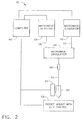
- FIG. 2 is a schematic illustration of an exemplary embodiment of the various components of an evanescent microwave microscope system 40 that includes an evanescent microwave probe 42.
- Probe 42 is capacitively coupled to a microwave circulator 44 by a coaxial cable 46 and a coupling capacitor 48.
- Coaxial cable 46 can also be referred to as a transmission line 46.
- Capacitor 48 is variable so the range of resonance can be tuned.
- a microwave generator 50 is connected to microwave circulator 44 by a coaxial cable 52. Any suitable microwave generator can be used, for example, sweep generator HP8350B commercially available from Hewlett Packard.
- a microwave detector 54 is also connected to microwave circulator 44 by a coaxial cable 56.
- Microwave detector 54 for example, a square law crystal microwave detector, permits a frequency modulated signal to be extracted from the microwave excitation signal.
- the frequency modulated signal is proportional to the magnitude of the reflected microwave radiation captured by probe 42.
- a computer 60 is operatively connected to microwave generator 50 to control and monitor generator 50.
- Computer 60 is also operatively coupled to detector 54 to collect scan data and perform data acquisition functions.
- a target mount 62 with X-Y axis control supports the component that is to be examined.
- Probe 42 is mounted on a Z-axis linear actuator 64 to provide controlled spacing of probe 42 and the part to be examined.
- Computer 60 is also operatively connected to target mount 62 and linear actuator 64 to precisely control the X-Y axis movement of target mount 62 and the Z-axis movement of actuator 64.
- FIG. 3 is a schematic illustration of an exemplary embodiment of evanescent microwave microscope probe 42.
- Probe 42 includes a center conductor 66 surrounded by an insulator 68 and an outer shield 70.
- An end portion (or tip) 72 of center conductor 66 is sharpened to a point and is plated with layer of at least one of silver, gold, platinum, palladium and alloys thereof.
- end portion 72 is plated with silver.
- end portion 72 is fabricated from silver gold, platinum, palladium or alloys thereof.
- Tip 72 of center conductor 66 extends through an aperture 74 in an end wall 76 of outer shield 70.
- Microwave probe 42 is a resonator type probe that is based on an open-transmission line. Such a resonator probe behaves as a parallel resonant circuit when the length of transmission line 46 is a multiple of ⁇ /2, where ⁇ is the wavelength of microwave energy in free space. The overall length of transmission line 46 is selected to give multiple resonances in the bandwidth of microwave generator 50.
- the reflection coefficient of probe 42 changes. Both the resonance frequency to and the quality factor Q of probe 42 are affected by the presence of the sample.
- the amount of change in the resonance depends primarily on the microwave properties of the sample as well as the distance d between tip 72 and the sample, and the effective area A eff of probe tip 72. Keeping A eff and d constant, probe 42 is scanned over the sample and variations in the microwave properties of the sample are mapped. Changes in the substrate surface (ground plane), defect layer properties, dielectric constant, and electrical conductivity affect the reflection coefficient. These properties are directly related to the quality of the surface of the metal component and the thickness and severity of any machining induced damaged surface layers.
- machining of turbine components causes a distortion of the microstructural features immediately adjacent to the machined surface.
- This distortion varies in degree of damage from minor cold working, exhibited by curved crystallographic grain boundaries in the direction of cold work, to a refined crystallographic grain structure that appears as a distinguishable layer at the material surface.
- a difference exists in the conductivity/dielectric properties of the unaffected material and the refined crystallographic grain structure generated by machining at the material surface. Therefore, changes in the machining induced surface layer affect the measurements of the evanescent microwave microscopy.
- Figure 4 is a schematic sectional view of a gas turbine engine component 80 with a machining induced surface defect layer 82.
- Defect layer 82 has a conductivity, dependent on the properties of defect layer 82 such as a thickness T that is measurable by evanescent microwave microscope system 40 with evanescent microwave probe 42.
- Thickness T of defect layer 82 can vary between about 0.0001 inch to about 0.002 inch (about 2.5 ⁇ to about 50.0 ⁇ ) and is very difficult to accurately measure using conventional optical metallography.
- component 80 To scan component 80 to detect a possible machine induced surface defect layer 82, component 80 is mounted on target mount 62. The distance between component 82 and probe tip 72 is set to a predetermined value by activating linear actuator 64. Component 80 is then scanned by moving component 80 in relation to probe 42 by using the X-Y axis control function of target mount 62. During the scanning of component 80, microwave generator 50 generates a microwave signal that is directed to probe 42 through microwave circulator 44. Detector 54 extracts frequency modulated signal data from the microwave excitation signal that is proportional to the magnitude of the reflected microwave radiation captured by probe 42. Computer 60 collects and process the detected scan data during the scanning process.
- evanescent microwave probe 42 is a resonant cavity having an aperture, for example, a rectangular resonant cavity having an aperture of about 0.1 ⁇ .
- the resonant cavity is a cylindrical resonant cavity having a slot shaped aperture.
- a cylindrical resonant cavity can be sized to conform to the shape of turbine component 80 to increase measurement sensitivity and spatial resolution.
- the above described evanescent microwave probe 42 permits detection and measurement of a machine induced surface defect layer 82 in gas turbine engine components.
- Field imaging scans of surface 84 of component 80 detect surface defect layer 82 and provide the scan data for determining the thickness T of defect layer 82.
Landscapes
- Engineering & Computer Science (AREA)
- Chemical & Material Sciences (AREA)
- Nanotechnology (AREA)
- Physics & Mathematics (AREA)
- Health & Medical Sciences (AREA)
- General Health & Medical Sciences (AREA)
- General Physics & Mathematics (AREA)
- Nuclear Medicine, Radiotherapy & Molecular Imaging (AREA)
- Radiology & Medical Imaging (AREA)
- Crystallography & Structural Chemistry (AREA)
- Optics & Photonics (AREA)
- Biophysics (AREA)
- General Engineering & Computer Science (AREA)
- Life Sciences & Earth Sciences (AREA)
- Mechanical Engineering (AREA)
- Analytical Chemistry (AREA)
- Length-Measuring Devices Using Wave Or Particle Radiation (AREA)
- Length Measuring Devices With Unspecified Measuring Means (AREA)
Abstract
A non-destructive method of detecting and measuring machining induced
surface defects on gas turbine engine components is provided. In an
exemplary embodiment, the method includes positioning an evanescent
microwave microscope probe adjacent a turbine component surface, and
scanning the turbine component surface by moving at least one of the
evanescent microwave microscope probe and the component surface in an x-y
plane while maintaining a predetermined distance between the probe and
the component surface constant.
Description
- This invention relates generally to non-destructive examinations of gas turbine engine components, and more particularly to non-destructive evaluations of machining induced surface defects on gas turbine engine components.
- A gas turbine engine includes a compressor for compressing air which channeled to a combustor and mixed with a fuel, wherein the mixture is ignited for generating hot combustion gases. The combustion gases are channeled to a turbine, which extracts energy from the combustion gases for powering the compressor, as well as producing useful work to propel an aircraft in flight or to power a load, such as an electrical generator. Increased efficiency in gas turbine engines is facilitated at least in part by an increase in the operating temperature of the combustor.
- Machining process, for example, broaching on gas turbine engine components can produce a surface damaged metallurgical layer. This surface damaged layer can result in reduced low cycle fatigue (LCF) lives. Machining induced surface damaged layers are typically measured with optical metallography. These damaged layers are about 0.001 inch (25 micrometers (µ)) or less in thickness, which approaches the accuracy limit of optical metallography. This is especially true at free surfaces which suffer from rounding during metallurgical sample preparation. It has been shown that optical metallography measurements can vary from about 50 percent to 150 percent of the depth of the measurement.
- Machining of turbine components causes a distortion of the microstructural features immediately adjacent to the machined surface. This distortion can vary in degree of damage from minor cold working, exhibited by curved crystallographic grain boundaries in the direction of cold work, to a refined crystallographic grain structure that appears as a distinguishable layer at the material surface. The thickness and severity associated with the cold worked and refined structures have been seen to change with machining process parameters. It is generally accepted that an increase in the severity and thickness of these layers will affected the low cycle fatigue life of the turbine component.
- In one aspect of the ionvention, a non-destructive method of detecting and measuring machining induced surface defects on gas turbine engine components is provided. The method includes positioning an evanescent microwave microscope probe adjacent a turbine component surface, and scanning the turbine component surface by moving at least one of the evanescent microwave microscope probe and the component surface in an x-y plane while maintaining a predetermined distance between the probe and the component surface constant.
- In another aspect, a non-destructive method of detecting and measuring machining induced surface defects on gas turbine engine components is provided. The method includes positioning an evanescent microwave microscope probe adjacent a turbine component surface, and scanning the turbine component by moving at least one of the evanescent microwave microscope probe and the component surface in relation to one another in an x-y plane while maintaining a distance between the probe and the turbine component surface constant. The evanescent microwave microscope probe includes a metal probe tip having an end sharpened to a point and further includes a conductive surface of at least one of silver, gold, platinum, palladium and alloys thereof.
- In another aspect, a non-destructive method of detecting and measuring machining induced surface defects on gas turbine engine components is provided. The method includes positioning an evanescent microwave microscope probe adjacent a turbine component surface, scanning the turbine component by moving at least one of the evanescent microwave microscope probe and the component surface in relation to one another in an x-y plane while maintaining a distance between the probe and the turbine component surface constant, and detecting reflected microwave radiation with a detector coupled to the evanescent microwave microscope probe. The evanescent microwave microscope probe includes a metal probe tip having an end sharpened to a point and further includes a conductive surface of at least one of silver, gold, platinum, palladium and alloys thereof.
- The invention will now be described in greater detail, by way of example, with reference to the drawings, in which:-
- Figure 1 is a schematic illustration of a gas turbine engine.
- Figure 2 is a schematic illustration of the various components of an evanescent microwave microscope with probe.
- Figure 3 is a schematic illustration of the evanescent microwave microscope probe shown in Figure 2.
- Figure 4 is a schematic sectional illustration of a gas turbine engine component having a surface damaged layer.
-
- Non-destructive examination of machining induced surface defects on gas turbine engine components using evanescent microwave microscopy is described in detail below. Evanescent microwave microscopy is used for imaging scans of the surface of turbine components with resolutions of λ/1000 or better, where λ is the wavelength of microwave energy in free space. Evanescent microwaves are capable of high resolution imaging using "near fields". This permits non-destructive imaging of materials that are sensitive to near field microstructure. The evanescent microwave probe measures frequency as it traverses a surface. The frequency is sensitive to probe distance, conductivity, dielectric, and changes of the near surface material. The cold worked surface of a machined metal exhibits a change in conductivity due to a change in grain size or localized melting at the near surface.
- In evanescent microwave field imaging, the fields are intentionally confined or restricted to regions that are significantly smaller than their wavelength. The fields in these regions are restricted and are unable to travel freely, so they evanesce or attenuate exponentially. These decaying fields are employed to scan over material objects much smaller than the wavelength of the traveling field exciting resonance in the microwave probe. This methodology enables the classical limit, i.e., Abbe barrier, to be exceeded. This limit on the spatial resolution or minimum resolvable size is 1/2 of the wave length λ of the electromagnetic excitation fields. To recover a signal, all the spatial frequency components contained within that signal are recovered. The basic principal is to closely scan in two or three dimensions a point like field source of a material object so that the evanescent field is powerful enough to interact with the properties of the material, such as a thermal barrier coating. This results in an image with resolved features significantly smaller than the Abbe limit and governed by the characteristic size and conductivity of the probe tip.
- Referring to the drawings, Figure 1 is a schematic illustration of an exemplary
gas turbine engine 10 including alow pressure compressor 12, ahigh pressure compressor 14, and acombustor assembly 16.Engine 10 also includes ahigh pressure turbine 18, and alow pressure turbine 20.Compressor 12 andturbine 20 are coupled by afirst shaft 24, andcompressor 14 andturbine 18 are coupled by asecond shaft 26. - In operation, air flows through
low pressure compressor 12 from an inlet ofengine 10 and compressed air is supplied fromlow pressure compressor 12 tohigh pressure compressor 14. Compressed air is then delivered tocombustor assembly 16 where it is mixed with fuel and ignited. The combustion gases are channeled fromcombustor 16 to driveturbines - Figure 2 is a schematic illustration of an exemplary embodiment of the various components of an evanescent
microwave microscope system 40 that includes anevanescent microwave probe 42.Probe 42 is capacitively coupled to amicrowave circulator 44 by acoaxial cable 46 and acoupling capacitor 48.Coaxial cable 46 can also be referred to as atransmission line 46.Capacitor 48 is variable so the range of resonance can be tuned. Amicrowave generator 50 is connected tomicrowave circulator 44 by acoaxial cable 52. Any suitable microwave generator can be used, for example, sweep generator HP8350B commercially available from Hewlett Packard. Amicrowave detector 54 is also connected tomicrowave circulator 44 by acoaxial cable 56.Microwave detector 54, for example, a square law crystal microwave detector, permits a frequency modulated signal to be extracted from the microwave excitation signal. The frequency modulated signal is proportional to the magnitude of the reflected microwave radiation captured byprobe 42. Acomputer 60 is operatively connected tomicrowave generator 50 to control andmonitor generator 50.Computer 60 is also operatively coupled todetector 54 to collect scan data and perform data acquisition functions. - A
target mount 62 with X-Y axis control supports the component that is to be examined.Probe 42 is mounted on a Z-axislinear actuator 64 to provide controlled spacing ofprobe 42 and the part to be examined.Computer 60 is also operatively connected totarget mount 62 andlinear actuator 64 to precisely control the X-Y axis movement oftarget mount 62 and the Z-axis movement ofactuator 64. - Figure 3 is a schematic illustration of an exemplary embodiment of evanescent
microwave microscope probe 42.Probe 42 includes acenter conductor 66 surrounded by aninsulator 68 and anouter shield 70. An end portion (or tip) 72 ofcenter conductor 66 is sharpened to a point and is plated with layer of at least one of silver, gold, platinum, palladium and alloys thereof. In the exemplary embodiment,end portion 72 is plated with silver. In alternate embodiments,end portion 72 is fabricated from silver gold, platinum, palladium or alloys thereof. The higher conductivity of silver, gold, platinum, and palladium increases the quality factor Q ofprobe 42. High Q values promote high sensitivity ofprobe 42.Tip 72 ofcenter conductor 66 extends through anaperture 74 in anend wall 76 ofouter shield 70. -
Microwave probe 42 is a resonator type probe that is based on an open-transmission line. Such a resonator probe behaves as a parallel resonant circuit when the length oftransmission line 46 is a multiple of λ/2, where λ is the wavelength of microwave energy in free space. The overall length oftransmission line 46 is selected to give multiple resonances in the bandwidth ofmicrowave generator 50. - When a sample object is placed
adjacent probe tip 72, the reflection coefficient ofprobe 42 changes. Both the resonance frequency to and the quality factor Q ofprobe 42 are affected by the presence of the sample. The amount of change in the resonance (df and dQ) depends primarily on the microwave properties of the sample as well as the distance d betweentip 72 and the sample, and the effective area Aeff ofprobe tip 72. Keeping Aeff and d constant,probe 42 is scanned over the sample and variations in the microwave properties of the sample are mapped. Changes in the substrate surface (ground plane), defect layer properties, dielectric constant, and electrical conductivity affect the reflection coefficient. These properties are directly related to the quality of the surface of the metal component and the thickness and severity of any machining induced damaged surface layers. Particularly, machining of turbine components causes a distortion of the microstructural features immediately adjacent to the machined surface. This distortion varies in degree of damage from minor cold working, exhibited by curved crystallographic grain boundaries in the direction of cold work, to a refined crystallographic grain structure that appears as a distinguishable layer at the material surface. A difference exists in the conductivity/dielectric properties of the unaffected material and the refined crystallographic grain structure generated by machining at the material surface. Therefore, changes in the machining induced surface layer affect the measurements of the evanescent microwave microscopy. - Figure 4 is a schematic sectional view of a gas
turbine engine component 80 with a machining inducedsurface defect layer 82.Defect layer 82 has a conductivity, dependent on the properties ofdefect layer 82 such as a thickness T that is measurable by evanescentmicrowave microscope system 40 withevanescent microwave probe 42. Thickness T ofdefect layer 82 can vary between about 0.0001 inch to about 0.002 inch (about 2.5 µ to about 50.0 µ) and is very difficult to accurately measure using conventional optical metallography. - To scan
component 80 to detect a possible machine inducedsurface defect layer 82,component 80 is mounted ontarget mount 62. The distance betweencomponent 82 andprobe tip 72 is set to a predetermined value by activatinglinear actuator 64.Component 80 is then scanned by movingcomponent 80 in relation to probe 42 by using the X-Y axis control function oftarget mount 62. During the scanning ofcomponent 80,microwave generator 50 generates a microwave signal that is directed to probe 42 throughmicrowave circulator 44.Detector 54 extracts frequency modulated signal data from the microwave excitation signal that is proportional to the magnitude of the reflected microwave radiation captured byprobe 42.Computer 60 collects and process the detected scan data during the scanning process. - In an alternative embodiment,
evanescent microwave probe 42 is a resonant cavity having an aperture, for example, a rectangular resonant cavity having an aperture of about 0.1λ. In another alternate embodiment, the resonant cavity is a cylindrical resonant cavity having a slot shaped aperture. A cylindrical resonant cavity can be sized to conform to the shape ofturbine component 80 to increase measurement sensitivity and spatial resolution. - The above described
evanescent microwave probe 42 permits detection and measurement of a machine inducedsurface defect layer 82 in gas turbine engine components. Field imaging scans ofsurface 84 ofcomponent 80 detectsurface defect layer 82 and provide the scan data for determining the thickness T ofdefect layer 82.
Claims (10)
- A non-destructive method of detecting and measuring machining induced surface defects on gas turbine engine components (80), said method comprising:positioning an evanescent microwave microscope probe (42) adjacent a turbine component surface (84); andscanning the turbine component surface by moving at least one of the evanescent microwave microscope probe and the component surface in an x-y plane while maintaining a predetermined distance between the probe and the component surface constant.
- A method in accordance with Claim 1 wherein the evanescent microwave microscope probe (42) comprises a metal probe tip (72) having an end sharpened to a point and further comprises a conductive surface of at least one of silver, gold, platinum, palladium and alloys thereof, said positioning an evanescent microwave microscope probe adjacent a turbine component surface (84) comprises positioning the sharpened probe tip a predetermined distance from the turbine component surface.
- A method in accordance with Claim 2 wherein a detector (54) is coupled to the evanescent microwave microscope probe (42), said method further comprises detecting reflected microwave radiation with the detector coupled to the evanescent microwave microscope probe.
- A method in accordance with Claim 3 wherein the detector (54) is coupled to a computer (60), said method further comprises sending detected reflected microwave radiation data to the computer.
- A method in accordance with Claim 4 further comprises generating graphical plots from detected reflected microwave radiation data showing the morphology of the component surface (84).
- A method in accordance with Claim 4 further comprising calculating a thickness of a surface damaged layer (82) of the component surface (84) at each scan point.
- A non-destructive method of detecting and measuring machining induced surface defects on gas turbine engine components (80), said method comprising:wherein the evanescent microwave microscope probe comprises a metal probe tip (72) having an end sharpened to a point and further comprises a conductive surface of at least one of silver, gold, platinum, palladium and alloys thereof.positioning an evanescent microwave microscope probe (42) adjacent a turbine component surface (84); andscanning the turbine component by moving at least one of the evanescent microwave microscope probe and the component surface in relation to one another in an x-y plane while maintaining a distance between the probe and the turbine component surface constant;
- A method in accordance with Claim 7 wherein the evanescent microwave microscope probe (72) is coupled to a detector (54), said method further comprises detecting reflected microwave radiation with the detector coupled to the evanescent microwave microscope probe.
- A method in accordance with Claim 8 wherein the detector (54) is coupled to a computer (60), said method further comprises sending detected reflected microwave radiation data to the computer.
- A method in accordance with Claim 9 further comprising:generating graphical plots from detected reflected microwave radiation data showing the morphology of the turbine component surface (84); and.calculating a thickness of a surface defective layer (82) of the component surface at each scan point.
Applications Claiming Priority (2)
| Application Number | Priority Date | Filing Date | Title |
|---|---|---|---|
| US439696 | 1995-05-12 | ||
| US10/439,696 US7019537B2 (en) | 2003-05-16 | 2003-05-16 | Non-destructive determination of machining induced surface defects on metal parts |
Publications (1)
| Publication Number | Publication Date |
|---|---|
| EP1484768A1 true EP1484768A1 (en) | 2004-12-08 |
Family
ID=33159460
Family Applications (1)
| Application Number | Title | Priority Date | Filing Date |
|---|---|---|---|
| EP04252806A Ceased EP1484768A1 (en) | 2003-05-16 | 2004-05-14 | Non-destructive determination of machining induced surface defects on metal parts by evanescent microwave microscopy |
Country Status (2)
| Country | Link |
|---|---|
| US (1) | US7019537B2 (en) |
| EP (1) | EP1484768A1 (en) |
Families Citing this family (15)
| Publication number | Priority date | Publication date | Assignee | Title |
|---|---|---|---|---|
| DE10359930A1 (en) * | 2003-01-23 | 2004-08-05 | Siemens Ag | Determining method of the demands on rotating blades in a current machine, blades being fixed or arranged on a rotor shaft |
| US8760174B2 (en) * | 2008-06-26 | 2014-06-24 | Wright State University | Evanescent microwave microscopy probe and methodology |
| US8142288B2 (en) * | 2009-05-08 | 2012-03-27 | Sony Computer Entertainment America Llc | Base station movement detection and compensation |
| US8333116B2 (en) * | 2010-06-30 | 2012-12-18 | Westinghouse Electric Company Llc | Inspection vehicle for a turbine disk |
| US8120522B2 (en) * | 2010-11-30 | 2012-02-21 | General Electric Company | System and method for inspecting a wind turbine blade |
| EP2620741A1 (en) * | 2012-01-24 | 2013-07-31 | Johann Hinken | Device for measuring coating thickness |
| US9395337B2 (en) | 2013-03-15 | 2016-07-19 | Digital Wind Systems, Inc. | Nondestructive acoustic doppler testing of wind turbine blades from the ground during operation |
| US9453500B2 (en) | 2013-03-15 | 2016-09-27 | Digital Wind Systems, Inc. | Method and apparatus for remote feature measurement in distorted images |
| WO2014144496A1 (en) * | 2013-03-15 | 2014-09-18 | Bruker Nano, Inc. | Chemical nano-identification of a sample using normalized near-field spectroscopy |
| US9194843B2 (en) | 2013-03-15 | 2015-11-24 | Digital Wind Systems, Inc. | Method and apparatus for monitoring wind turbine blades during operation |
| US9330449B2 (en) | 2013-03-15 | 2016-05-03 | Digital Wind Systems, Inc. | System and method for ground based inspection of wind turbine blades |
| CN105044132B (en) * | 2015-05-15 | 2019-11-12 | 深圳市太赫兹科技有限公司 | Method and system for determining source detection distance of microwave probe |
| US10878554B2 (en) | 2017-10-26 | 2020-12-29 | United Technologies Corporation | Defect detection and measurement method |
| RU201679U1 (en) * | 2020-08-12 | 2020-12-28 | федеральное государственное бюджетное образовательное учреждение высшего образования "Ульяновский государственный технический университет" | DEVICE FOR DIAGNOSTICS AND CONTROL BY RADIO WAVE METHOD OF POLYMERIC COMPOSITE MATERIALS |
| US12123839B2 (en) * | 2021-08-13 | 2024-10-22 | Rtx Corporation | Forming and/or inspecting cooling aperture(s) in a turbine engine component |
Citations (2)
| Publication number | Priority date | Publication date | Assignee | Title |
|---|---|---|---|---|
| US5748003A (en) * | 1991-07-29 | 1998-05-05 | Colorado State University Research Foundation | Microwaves used for determining fatigue and surface crack features on metal surfaces |
| US5821410A (en) * | 1996-09-20 | 1998-10-13 | Regents Of The University Of California | Scanning tip microwave near field microscope |
Family Cites Families (7)
| Publication number | Priority date | Publication date | Assignee | Title |
|---|---|---|---|---|
| US5572228A (en) * | 1995-02-01 | 1996-11-05 | Physical Optics Corporation | Evanescent coupling antenna and method for the utilization thereof |
| US5936237A (en) * | 1995-07-05 | 1999-08-10 | Van Der Weide; Daniel Warren | Combined topography and electromagnetic field scanning probe microscope |
| US5749229A (en) * | 1995-10-13 | 1998-05-12 | General Electric Company | Thermal spreading combustor liner |
| US5781007A (en) * | 1995-10-24 | 1998-07-14 | General Electric Company | Portable three axis scanner to inspect a gas turbine engine spool by eddy current or ultrasonic inspection |
| US5818242A (en) * | 1996-05-08 | 1998-10-06 | United Technologies Corporation | Microwave recess distance and air-path clearance sensor |
| US5900816A (en) * | 1997-06-18 | 1999-05-04 | Weaver; Jon Neal | Anti-shoplifting security system utilizing a modulated transmitter signal |
| US6173604B1 (en) * | 1996-09-20 | 2001-01-16 | The Regents Of The University Of California | Scanning evanescent electro-magnetic microscope |
-
2003
- 2003-05-16 US US10/439,696 patent/US7019537B2/en not_active Expired - Fee Related
-
2004
- 2004-05-14 EP EP04252806A patent/EP1484768A1/en not_active Ceased
Patent Citations (2)
| Publication number | Priority date | Publication date | Assignee | Title |
|---|---|---|---|---|
| US5748003A (en) * | 1991-07-29 | 1998-05-05 | Colorado State University Research Foundation | Microwaves used for determining fatigue and surface crack features on metal surfaces |
| US5821410A (en) * | 1996-09-20 | 1998-10-13 | Regents Of The University Of California | Scanning tip microwave near field microscope |
Non-Patent Citations (5)
| Title |
|---|
| CORROSION, vol. 40, no. 8, August 1984 (1984-08-01), USA, pages 409 - 413, ISSN: 0010-9312 * |
| DAROLIA R ET AL: "Effect of specimen surface preparation on room temperature tensile ductility of an Fe-containing NiAl single crystal alloy", INTERMETALLICS, ELSEVIER SCIENCE PUBLISHERS B.V, GB, vol. 4, no. 7, 1996, pages 505 - 516, XP004049203, ISSN: 0966-9795 * |
| DATABASE INSPEC [online] THE INSTITUTION OF ELECTRICAL ENGINEERS, STEVENAGE, GB; LENNON S J ET AL: "The influence of applied stress and surface finish on the pitting susceptibility of low alloy turbine disk steels in wet steam", XP002297335, Database accession no. 2352105 * |
| KLEISMIT R A ET AL: "Evanescent microwave sensor scanning for detection of sub-surface defects in wires", PROCEEDINGS: ELECTRICAL INSULATION CONFERENCE AND ELECTRICAL MANUFACTURING AND COIL WINDING CONFERENCE (CAT. NO.01CH37264) , CINCINNATI, USA, 16 October 2001 (2001-10-16) - 18 October 2001 (2001-10-18), IEEE PISCATAWAY, NJ, USA, pages 245 - 250, XP002297334, ISBN: 0-7803-7180-1 * |
| ROSNERB T ET AL: "High-frequency near field microscopy", REVIEW OF SCIENTIFIC INSTRUMENTS, AMERICAN INSTITUTE OF PHYSICS. NEW YORK, US, vol. 73, no. 7, July 2002 (2002-07-01), pages 2505 - 2525, XP002242021, ISSN: 0034-6748 * |
Also Published As
| Publication number | Publication date |
|---|---|
| US7019537B2 (en) | 2006-03-28 |
| US20040227525A1 (en) | 2004-11-18 |
Similar Documents
| Publication | Publication Date | Title |
|---|---|---|
| US6968730B2 (en) | Non-destructive evaluation of thermal barrier coatings in gas turbine engines | |
| US7019537B2 (en) | Non-destructive determination of machining induced surface defects on metal parts | |
| Albishi et al. | Microwaves-based high sensitivity sensors for crack detection in metallic materials | |
| US5748003A (en) | Microwaves used for determining fatigue and surface crack features on metal surfaces | |
| US8035400B2 (en) | High-resolution, nondestructive imaging of dielectric materials | |
| Yule et al. | Surface temperature condition monitoring methods for aerospace turbomachinery: Exploring the use of ultrasonic guided waves | |
| CN111089877A (en) | Nondestructive testing method and equipment for thermal barrier coating | |
| CN114486940A (en) | Resonance structure, metal nondestructive testing sensor, metal nondestructive testing system and metal nondestructive testing method | |
| Qaddoumi et al. | Microwave detection of stress-induced fatigue cracks in steel and potential for crack opening determination | |
| Li et al. | Applications of microwave techniques for aerospace composites | |
| Guorong et al. | Detection of surface crack on the substrate under thermal barrier coatings using microwave non-destructive evaluation | |
| Sezer et al. | Non-destructive microwave evaluation of TBC delamination induced by acute angle laser drilling | |
| ur Rahman et al. | Non-destructive testing and evaluation of surface-breaking cracks using microwave planar resonator probe | |
| US5374122A (en) | Method for quantifying porosity of parts of simple and complex geometries | |
| Barancos et al. | Experiments with Near-Field Microwave Imaging for Powder Bed Fusion Metal Additive Manufacturing | |
| Moll | Numerical and experimental analysis of defect detection in jointed electromagnetic waveguides | |
| Zoughi et al. | Measurement parameter optimization for surface crack detection in metals using an open-ended waveguide probe | |
| CN101044379A (en) | Method for determining the temperature of a surface coating | |
| Amir et al. | Open ended coaxial sensors with and without cavity for non-destructive applications | |
| Li et al. | Enhanced microwave waveguide probe-based methods for damage detection of GFRP composites | |
| Jinman et al. | Diagnosing laser-induced damage to optical thin films using peak sound pressure of shock waves | |
| Zoughi et al. | Microwave measurement-parameter optimization for detection of surface breaking hairline cracks in metals | |
| Sobkiewicz | Split ring resonator based probe for detection of subsurface defects in composite materials | |
| Han et al. | Terahertz Detection and Evaluation of Thermal Barrier Coating Thickness | |
| CN121163437A (en) | Film thickness and defect synchronous detection system and method based on double-probe microwave resonance |
Legal Events
| Date | Code | Title | Description |
|---|---|---|---|
| PUAI | Public reference made under article 153(3) epc to a published international application that has entered the european phase |
Free format text: ORIGINAL CODE: 0009012 |
|
| AK | Designated contracting states |
Kind code of ref document: A1 Designated state(s): AT BE BG CH CY CZ DE DK EE ES FI FR GB GR HU IE IT LI LU MC NL PL PT RO SE SI SK TR |
|
| AX | Request for extension of the european patent |
Extension state: AL HR LT LV MK |
|
| 17P | Request for examination filed |
Effective date: 20050608 |
|
| AKX | Designation fees paid |
Designated state(s): DE FR GB |
|
| STAA | Information on the status of an ep patent application or granted ep patent |
Free format text: STATUS: THE APPLICATION HAS BEEN REFUSED |
|
| 18R | Application refused |
Effective date: 20091218 |