EP1484598A1 - Method of judging homogenization/reaction completion and method of measuring solution concentration using the same - Google Patents
Method of judging homogenization/reaction completion and method of measuring solution concentration using the same Download PDFInfo
- Publication number
- EP1484598A1 EP1484598A1 EP03708571A EP03708571A EP1484598A1 EP 1484598 A1 EP1484598 A1 EP 1484598A1 EP 03708571 A EP03708571 A EP 03708571A EP 03708571 A EP03708571 A EP 03708571A EP 1484598 A1 EP1484598 A1 EP 1484598A1
- Authority
- EP
- European Patent Office
- Prior art keywords
- liquid
- time
- test liquid
- reagent
- measurement
- Prior art date
- Legal status (The legal status is an assumption and is not a legal conclusion. Google has not performed a legal analysis and makes no representation as to the accuracy of the status listed.)
- Withdrawn
Links
Images






Classifications
-
- G—PHYSICS
- G01—MEASURING; TESTING
- G01N—INVESTIGATING OR ANALYSING MATERIALS BY DETERMINING THEIR CHEMICAL OR PHYSICAL PROPERTIES
- G01N21/00—Investigating or analysing materials by the use of optical means, i.e. using sub-millimetre waves, infrared, visible or ultraviolet light
- G01N21/17—Systems in which incident light is modified in accordance with the properties of the material investigated
- G01N21/25—Colour; Spectral properties, i.e. comparison of effect of material on the light at two or more different wavelengths or wavelength bands
- G01N21/27—Colour; Spectral properties, i.e. comparison of effect of material on the light at two or more different wavelengths or wavelength bands using photo-electric detection ; circuits for computing concentration
- G01N21/272—Colour; Spectral properties, i.e. comparison of effect of material on the light at two or more different wavelengths or wavelength bands using photo-electric detection ; circuits for computing concentration for following a reaction, e.g. for determining photometrically a reaction rate (photometric cinetic analysis)
-
- B—PERFORMING OPERATIONS; TRANSPORTING
- B01—PHYSICAL OR CHEMICAL PROCESSES OR APPARATUS IN GENERAL
- B01F—MIXING, e.g. DISSOLVING, EMULSIFYING OR DISPERSING
- B01F25/00—Flow mixers; Mixers for falling materials, e.g. solid particles
- B01F25/20—Jet mixers, i.e. mixers using high-speed fluid streams
- B01F25/21—Jet mixers, i.e. mixers using high-speed fluid streams with submerged injectors, e.g. nozzles, for injecting high-pressure jets into a large volume or into mixing chambers
-
- G—PHYSICS
- G01—MEASURING; TESTING
- G01N—INVESTIGATING OR ANALYSING MATERIALS BY DETERMINING THEIR CHEMICAL OR PHYSICAL PROPERTIES
- G01N21/00—Investigating or analysing materials by the use of optical means, i.e. using sub-millimetre waves, infrared, visible or ultraviolet light
- G01N21/17—Systems in which incident light is modified in accordance with the properties of the material investigated
- G01N21/47—Scattering, i.e. diffuse reflection
- G01N21/49—Scattering, i.e. diffuse reflection within a body or fluid
- G01N21/51—Scattering, i.e. diffuse reflection within a body or fluid inside a container, e.g. in an ampoule
-
- G—PHYSICS
- G01—MEASURING; TESTING
- G01N—INVESTIGATING OR ANALYSING MATERIALS BY DETERMINING THEIR CHEMICAL OR PHYSICAL PROPERTIES
- G01N21/00—Investigating or analysing materials by the use of optical means, i.e. using sub-millimetre waves, infrared, visible or ultraviolet light
- G01N21/17—Systems in which incident light is modified in accordance with the properties of the material investigated
- G01N21/47—Scattering, i.e. diffuse reflection
- G01N21/49—Scattering, i.e. diffuse reflection within a body or fluid
- G01N21/53—Scattering, i.e. diffuse reflection within a body or fluid within a flowing fluid, e.g. smoke
- G01N21/532—Scattering, i.e. diffuse reflection within a body or fluid within a flowing fluid, e.g. smoke with measurement of scattering and transmission
-
- G—PHYSICS
- G01—MEASURING; TESTING
- G01N—INVESTIGATING OR ANALYSING MATERIALS BY DETERMINING THEIR CHEMICAL OR PHYSICAL PROPERTIES
- G01N21/00—Investigating or analysing materials by the use of optical means, i.e. using sub-millimetre waves, infrared, visible or ultraviolet light
- G01N21/17—Systems in which incident light is modified in accordance with the properties of the material investigated
- G01N21/59—Transmissivity
-
- G—PHYSICS
- G01—MEASURING; TESTING
- G01N—INVESTIGATING OR ANALYSING MATERIALS BY DETERMINING THEIR CHEMICAL OR PHYSICAL PROPERTIES
- G01N21/00—Investigating or analysing materials by the use of optical means, i.e. using sub-millimetre waves, infrared, visible or ultraviolet light
- G01N21/75—Systems in which material is subjected to a chemical reaction, the progress or the result of the reaction being investigated
- G01N21/77—Systems in which material is subjected to a chemical reaction, the progress or the result of the reaction being investigated by observing the effect on a chemical indicator
- G01N21/82—Systems in which material is subjected to a chemical reaction, the progress or the result of the reaction being investigated by observing the effect on a chemical indicator producing a precipitate or turbidity
-
- G—PHYSICS
- G01—MEASURING; TESTING
- G01N—INVESTIGATING OR ANALYSING MATERIALS BY DETERMINING THEIR CHEMICAL OR PHYSICAL PROPERTIES
- G01N21/00—Investigating or analysing materials by the use of optical means, i.e. using sub-millimetre waves, infrared, visible or ultraviolet light
- G01N21/01—Arrangements or apparatus for facilitating the optical investigation
- G01N21/03—Cuvette constructions
- G01N2021/0325—Cells for testing reactions, e.g. containing reagents
-
- G—PHYSICS
- G01—MEASURING; TESTING
- G01N—INVESTIGATING OR ANALYSING MATERIALS BY DETERMINING THEIR CHEMICAL OR PHYSICAL PROPERTIES
- G01N21/00—Investigating or analysing materials by the use of optical means, i.e. using sub-millimetre waves, infrared, visible or ultraviolet light
- G01N21/17—Systems in which incident light is modified in accordance with the properties of the material investigated
- G01N21/47—Scattering, i.e. diffuse reflection
- G01N21/49—Scattering, i.e. diffuse reflection within a body or fluid
- G01N21/51—Scattering, i.e. diffuse reflection within a body or fluid inside a container, e.g. in an ampoule
- G01N2021/513—Cuvettes for scattering measurements
-
- G—PHYSICS
- G01—MEASURING; TESTING
- G01N—INVESTIGATING OR ANALYSING MATERIALS BY DETERMINING THEIR CHEMICAL OR PHYSICAL PROPERTIES
- G01N21/00—Investigating or analysing materials by the use of optical means, i.e. using sub-millimetre waves, infrared, visible or ultraviolet light
- G01N21/75—Systems in which material is subjected to a chemical reaction, the progress or the result of the reaction being investigated
- G01N2021/755—Comparing readings with/without reagents, or before/after reaction
-
- G—PHYSICS
- G01—MEASURING; TESTING
- G01N—INVESTIGATING OR ANALYSING MATERIALS BY DETERMINING THEIR CHEMICAL OR PHYSICAL PROPERTIES
- G01N21/00—Investigating or analysing materials by the use of optical means, i.e. using sub-millimetre waves, infrared, visible or ultraviolet light
- G01N21/75—Systems in which material is subjected to a chemical reaction, the progress or the result of the reaction being investigated
- G01N21/77—Systems in which material is subjected to a chemical reaction, the progress or the result of the reaction being investigated by observing the effect on a chemical indicator
- G01N2021/7769—Measurement method of reaction-produced change in sensor
- G01N2021/7783—Transmission, loss
-
- G—PHYSICS
- G01—MEASURING; TESTING
- G01N—INVESTIGATING OR ANALYSING MATERIALS BY DETERMINING THEIR CHEMICAL OR PHYSICAL PROPERTIES
- G01N2201/00—Features of devices classified in G01N21/00
- G01N2201/12—Circuits of general importance; Signal processing
- G01N2201/122—Kinetic analysis; determining reaction rate
- G01N2201/1222—Endpoint determination; reaction time determination
Definitions
- the present invention relates to solution concentration measuring methods and solution concentration measuring apparatuses for determining the concentration of a solute dissolved in a test liquid, for example, protein. More specifically, the present invention measures the concentration of a specific component contained in a test liquid, by mixing a reagent liquid into the test liquid to change the optical property of the test liquid deriving from only the specific component. Particularly, by mixing the test liquid and the reagent liquid to coagulate the protein component, and detecting the decrease in light transmitted through the test liquid after the mixing and/or the increase in the intensity of light scattered during the propagation through the test liquid, the present invention measures the concentration of this protein component.
- the present invention determines that the test liquid and the reagent liquid have been sufficiently stirred until homogenized, when the relation between the elapsed period of time since the mixing and the intensity of light transmitted through the liquid mixture or the intensity of scattered light satisfies a predetermined condition. Also, by this, the present invention can simultaneously determine that the reaction between the test liquid and the reagent liquid has been completed. In this way, by determining homogenization and/or reaction completion, it is possible to set the measurement time necessary and sufficient, and to reduce the measurement time. In the case of not controlling the temperature of the liquid mixture of the test liquid and the reagent liquid, in particular, the present invention can realize high reliability with a necessary and sufficient measurement time and provide highly practical methods for measuring solution concentration.
- a test liquid and a reagent liquid are mixed in a predetermined volume ratio and sufficiently stirred until the resultant mixture becomes homogeneous, to prepare a liquid mixture. Then, the liquid mixture is stirred at a predetermined temperature, and upon the lapse of a predetermined period of time, the optical property of the liquid mixture is measured to determine the concentration.
- concentration of a specific component by utilizing biochemical reactions, such as enzyme reactions and antigen-antibody reactions
- the predetermined period of time to a period of time within which the reaction sufficiently reaches completion.
- a sufficient period of time for the completion of the reaction is set in consideration of the concentration of the test liquid at the predetermined temperature.
- optical property is measured under conditions where the liquid mixture is sufficiently stirred until homogenized and the reaction would never fail to reach completion. That is, sufficient conditions for homogenization and reaction completion are set.
- a test liquid is retained in a sample cell that is structured to propagate light through the test liquid.
- This sample cell is in the form of a rectangular parallelepiped, made of, for example, glass, and has transmission faces that are transparent. Thus, light can be propagated through the test liquid.
- the top part of this sample cell is open, and a predetermined volume of a test liquid is introduced from the top part using a dropper, a pipette, a syringe, or the like. Subsequently, a predetermined volume of a reagent liquid is mixed thereinto such that the volume ratio of the test liquid to the reagent liquid is constant. Thereafter, the resultant mixture is sufficiently stirred in the sample cell with a stirring stick, stirrer, or the like until it becomes homogenized, and the whole sample cell is kept at a predetermined temperature, for example, in a constant-temperature bath. After the lapse of a predetermined period of time, the sample cell is remounted onto the optical system, and the optical property of the liquid mixture in the sample cell is measured.
- an object of the present invention is to provide a highly reliable method of measuring solution concentration capable of easy automation, as well as a highly reliable, small-sized apparatus of measuring solution concentration capable of easy automation.
- the present invention further provides a solution concentration measuring method and a solution concentration measuring apparatus which can reduce the time necessary for homogenization and/or reaction completion to the requisite minimum, thereby enabling a reduction in measurement time.
- the present invention relates to a method for determining homogenization and/or reaction completion, including the steps of: (1) mixing a test liquid and a reagent liquid to obtain a liquid mixture; (2) measuring an optical property of the liquid mixture after the mixing continuously or a plurality of times discretely; (3) obtaining a relation between the measured value of the optical property obtained and the elapsed period of time since the start of the measurement after the mixing; and (4) determining, on the basis of the relation, whether the test liquid and the reagent liquid have been substantially homogeneously mixed with each other and/or a reaction between the test liquid and the reagent liquid has been substantially completed.
- the steps (1) to (4) are performed in this order.
- the step (3) is preferably a step of obtaining dS1/dt (wherein S1 is the measured value of the optical property obtained and T is the elapsed period of time since the start of the measurement after the mixing), and the step (4) is preferably a step of determining that the test liquid and the reagent liquid have been substantially homogeneously mixed with each other and/or the reaction between the test liquid and the reagent liquid has been substantially completed, when the dS1/dt has continuously been in a predetermined range R1 for a predetermined period of time T1 or longer.
- the step (3) is preferably a step of obtaining (dS1/dt)/S1 (wherein S1 is the measured value of the optical property obtained and T is the elapsed period of time since the start of the measurement after the mixing), and the step (4) is preferably a step of determining that the test liquid and the reagent liquid have been substantially homogeneously mixed with each other and/or the reaction between the test liquid and the reagent liquid has been substantially completed, when the (dS1/dt)/S1 has continuously been in a predetermined range R2 for a predetermined period of time T2 or longer.
- the present invention pertains to a method for determining homogenization and/or reaction completion, including the steps of: (1) mixing a test liquid and a reagent liquid to obtain a liquid mixture; (2) measuring an optical property of the test liquid and the liquid mixture continuously, or, measuring an optical property of the test liquid at least once and measuring an optical property of the liquid mixture after the mixing a plurality of times discretely; (3) obtaining a relation between the measured value of the optical property obtained and the elapsed period of time since the start of the measurement after the mixing; and (4) determining, on the basis of the relation, that the test liquid and the reagent liquid have been substantially homogeneously mixed with each other and/or the reaction between the test liquid and the reagent liquid has been substantially completed.
- the steps (1) to (4) are performed in this order.
- the step (3) is preferably a step of obtaining (dS1/dt)/(S1-S0) (wherein S0 is the measured value of the optical property of the test liquid, S1 is the measured value of the optical property of the liquid mixture, and T is the elapsed period of time since the start of the measurement after the mixing), and the step (4) is preferably a step of determining that the test liquid and the reagent liquid have been substantially homogeneously mixed with each other and/or the reaction between the test liquid and the reagent liquid has been substantially completed, when the (dS1/dt)/(S1-S0) has continuously been in a predetermined range R3 for a predetermined period of time T3 or longer.
- the present invention is directed to a method for measuring solution concentration, wherein the homogenization of the mixture of the test liquid and the reagent liquid and/or the substantial completion of the reaction therebetween are determined according to the above-mentioned method for determining homogenization and/or reaction completion, and then the concentration of a specific component of the test liquid is determined based on the measured value S1 or the measured values of S0 and S1.
- This method for measuring solution concentration preferably includes the step of mixing another reagent liquid with the test liquid, after determining that the test liquid and the reagent liquid have been homogeneously mixed and/or the reaction therebetween has been substantially completed.
- another reagent liquid is mixed with the test liquid upon the lapse of a predetermined period of time T4 after determining that the test liquid and the reagent liquid have been homogeneously mixed and/or the reaction therebetween has been substantially completed, and the optical property of the liquid mixture is measured prior to the lapse of the predetermined period of time T4.
- the present invention also relates to an apparatus for measuring solution concentration, including: a light source that irradiates a test liquid with light; a sample cell that retains the test liquid; a photosensor 1 that detects light transmitted through the test liquid and/or a photosensor 2 that detects light scattered while the light is propagated through the test liquid; and a computer that analyzes an output signal of the photosensor 1 and/or the photosensor 2, wherein based on the above-mentioned method for measuring solution concentration, the computer analyzes the output signal of the pohotosensor 1 and/or the photosensor 2 to calculate the concentration of the test liquid.
- the computer preferably includes controlling means for measuring an optical property of the liquid mixture obtained by mixing a test liquid and a reagent liquid continuously or a plurality of times discretely, obtaining a relation between the measured value of the optical property obtained and the elapsed period of time since the start of the measurement after the mixing, determining, on the basis of the relation, that the test liquid and the reagent liquid have been substantially homogeneously mixed with each other and/or a reaction between the test liquid and the reagent liquid has been substantially completed, and determining the concentration of a specific component in the test liquid based on the measured value.
- controlling means of the computer may measure the optical property of the test liquid and the liquid mixture continuously, or, it may measure the optical property of the test liquid at least once and measure the optical property of the liquid mixture after the mixing a plurality of times discretely.
- the apparatus for measuring solution concentration include an injector that injects a reagent liquid into the test liquid in the sample cell for mixing and that the injector be controlled by the computer or the controlling means.
- the optical property of the test liquid be measured, using the light source, to determine the concentration of a specific component in the test liquid.
- a measurement be rendered invalid when homogenization and/or reaction completion has not been determined within a predetermined period of time T from the start of the measurement.
- the above-mentioned predetermined period of time T satisfy the relation T ⁇ T5 wherein T5 is the elapsed period of time since the start of a measurement until homogenization or reaction completion is determined by the above-mentioned method for determining homogenization and/or reaction completion.
- the substance that reacts with the analyte be an antibody that specifically reacts and combines with the analyte and that the signal related to the optical property that derives from the specific binding reaction be the turbidity of the liquid mixture.
- analyte be human albumin.
- the present invention relates to a solution concentration measuring method that qualitatively or quantitatively determines an analyte, by mixing a test liquid containing the analyte with a reagent liquid containing a substance that reacts with the analyte, and detecting a signal related to the optical property deriving from the reaction.
- the present invention relates to a method for determining homogenization and/or reaction completion, including the steps of: (1) mixing a test liquid and a reagent liquid to obtain a liquid mixture; (2) measuring an optical property of the liquid mixture after the mixing continuously or a plurality of times discretely, or, measuring an optical property of the test liquid and the liquid mixture continuously, or, measuring an optical property of the test liquid at least once and measuring an optical property of the liquid mixture after the mixing a plurality of times discretely; (3) obtaining a relation between the measured value of the optical property obtained and the elapsed period of time since the start of the measurement after the mixing; and (4) determining, on the basis of the relation, whether the test liquid and the reagent liquid have been substantially homogeneously mixed with each other and/or a reaction between the test liquid and the reagent liquid has been substantially completed.
- the present invention also provide a solution concentration measuring method and a solution concentration measuring apparatus using this method for measuring homogenization and/or reaction completion.
- Fig. 1 is a top view of a solution concentration measuring apparatus according to Embodiment 1 of the present invention.
- Fig. 2 is a partially cross-sectional side view of the solution concentration measuring apparatus according to Embodiment 1 of the present invention.
- the skeletal part of a sample cell 1 is composed of an aluminum container that is in the form of a rectangular parallelepiped and has an opening at the top.
- a glass plate, serving as an optical window, is fitted into a pair of side faces of the sample cell 1 to form an optical path, so that light can be transmitted through a test liquid (or a liquid mixture of a test liquid and a reagent liquid) retained in the sample cell 1.
- the distance between the optical windows optical length
- a and B are set to 0.8 cm and 0.4 cm, respectively, as a representative example to explain the present invention.
- an injection port 2 is provided in the edge of the side face of the sample cell 1 having no optical window, and the internal diameter (diameter) of the injection port 2 is 0.1 cm.
- the center of the vertical section of the injection port 2 is positioned at a distance x from the bottom face of the sample cell 1 and at a distance z from the optical window.
- Injection direction 10 is parallel to the faces having the optical windows and perpendicular to the direction of light propagation.
- x and y are set to 0.4 cm and 0.1 cm, respectively, as a representative example to explain the present invention.
- the substantially parallel light 4 has a wavelength of 780 nm, an intensity of 3.0 mW, and a beam diameter of 0.2 cm.
- the optical axis of this substantially parallel light 4 is parallel to the bottom face of the sample cell 1 and positioned at a distance of 0.4 cm from the bottom face. Therefore, the optical axis and the injection port 2 are positioned at the same height from the bottom face, and the optical axis of the substantially parallel light 4 and the injection axis extending from the center of the section of the injection port 2 in the injection direction 10 have a point of intersection in the solution in the sample cell 1.
- a photosensor 5 is a photosensor which detects light that has been transmitted through the test liquid.
- a pump 6 injects a reagent liquid from the injection port 2 into the test liquid in the sample cell 1.
- a computer 7 analyzes the output signal of the photosensor 5 and controls the pump 6.
- An arrow 8 schematically indicates the direction of the vortex that occurs in the sample cell 1 when the reagent liquid is injected from the injection port 2.
- the lowest part of liquid level 9 of the test liquid is positioned at a height h from the bottom face of the sample cell 1.
- the liquid level is defined as the level that is in contact with the lowest part of the liquid level 9 and parallel to the horizontal level. According to this definition, the injection direction is parallel to the liquid level in this embodiment.
- a dispersion obtained by homogeneously dispersing polystyrene fine particles having a mean diameter of 20 nm in pure water is charged into the sample cell 1 as the test liquid.
- the whole test liquid is homogeneously turbid.
- the polystyrene fine particles have a specific gravity close to that of pure water, and their particle size is also small.
- phenomena such as separation and precipitation do not occur during the period of time in which the method according to the present invention is carried out. However, if they have not been homogeneously dispersed due to insufficient stirring, such phenomena may occur.
- the change in the turbidity of the liquid containing fine particles due to diffusion involves no chemical reaction. Therefore, the turbidity of the whole test liquid depends solely on the degree of diffusion of the polystyrene fine particles, and hence, there is no need to take reaction speed into consideration. That is, the fact that the turbidity has been stabilized at a certain value means that the fine particles have been sufficiently spread throughout the liquid and homogeneously dispersed.
- the present invention is simplified for the purpose of explanation by selecting only the result of determination of the homogenization attained by the stirring of the present invention.
- test liquid containing the polystyrene fine particles was introduced into the sample cell 1.
- the volume of the test liquid introduced was 0.25 ml.
- the computer 7 was started to measure (record) the output signal of the photosensor 5. The changes over time in the output signal of the photosensor 5 after the start of the measurement following the introduction are shown in Fig. 3.
- Fig. 3 the elapsed period of time since the start of measurement of the output signal is plotted in abscissa, and the output signal of the photosensor 5 is plotted in ordinate.
- the computer 7 controlled the pump 6 so that pure water was injected from the injection port 2 over 2 seconds.
- the changes in the output signal of the photosensor 5 in the case of pure water injection, as described, are shown by solid lines in Fig. 3.
- "a", "b", “c”, and “d” show the changes in the output signal of the photosensor 5 resulting from the injection of 0.1 ml of pure water, 0.07 ml of pure water, 0.05 ml of water, and 0.03 ml of pure water, respectively.
- the solid lines “a” to “c” represented the cases where the liquid mixture of the test liquid and the pure water was sufficiently stirred until homogenized, while the solid line “d” represented the case where the liquid mixture could not be sufficiently stirred until homogenized.
- the method of the present invention determines whether or not the liquid mixture has been sufficiently stirred, i.e., whether or not the liquid mixture has become homogenized, based on the optical property of the liquid mixture, i.e., the output signal of the photosensor 5. Summing up, this method is an example of being able to reduce the measurement time by setting the waiting time from the start of a measurement until obtaining the result necessary and sufficient.
- the maximum period of time within which a measurement is performed is set in advance. This period refers to the longest waiting period of time from the start of the measurement until obtaining the result, and if a measurement takes more than this maximum period of time, this measurement is rendered invalid.
- This pre-set period of time is referred to as a predetermined period of time T.
- homogenization is determined when the amount of change in an output signal S1 of the photosensor 5 per unit time, i.e., a derivative signal dS1/dt, has continuously been in a predetermined range R1 for a predetermined period of time T1 within the predetermined period of time T.
- the liquid mixture is determined as having been homogenized when dS1/dt [V/S] has continuously been in a predetermined range R1 represented by formula (1) for a predetermined period of time T1 (1.5 seconds) or longer within a predetermined period of time T (60 seconds) after the start of a measurement.
- a predetermined period of time T1 1.5 seconds
- a predetermined period of time T 60 seconds
- the derivative signal dS1/dt may be in the predetermined range R1 for the predetermined period of time T1, even if the liquid mixture has not been homogenized due to insufficient stirring, particularly even if pure water regions are separated from fine particle regions.
- the liquid mixture has not been homogenized due to insufficient stirring, particularly even if pure water regions are separated from fine particle regions.
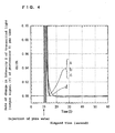
- Fig. 4 shows the derivative signal of output signal of the photosensor 5.
- the solid lines “a” to “d” of Fig. 3 correspond to the derivative values (dS/dt) of the signal intensities represented by the solid lines “a” to “c” and the dotted line “d” of Fig. 4, respectively.
- Fig. 4 in the same manner as in Fig. 3, during the period of about 2 seconds or more from the elapsed time of 10 seconds at which the injection of pure water was started, the flux of the injected pure water itself entered the optical path of the substantially parallel light 4. As a result, the intensity and the propagation direction of transmitted light were disturbed, causing a violent change in the derivative signal of output signal of the photosensor 5.
- Fig. 4 shows the derivative signal of output signal of the photosensor 5.
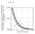
- Fig. 6 showed a graph obtained by enlarging the ordinate at zero and greater and enlarging the abscissa around 14.5 to 16.5 seconds in Fig. 4.
- ⁇ corresponds to "a”
- ⁇ corresponds to "b”
- ⁇ corresponds to "c”.
- "a" to "c” asymptotically approached zero.
- a point of time when the derivative signal dS1/dt of output signal of the photosensor 5 has continuously been in the predetermined range R1 represented by formula (1) for the predetermined period of time T1 (1.5 seconds) or longer within the predetermined period of time T (60 seconds) after the start of a measurement was found as follows.
- the derivative signal dS1/dt of output signal of the photosensor 5 became 5 ⁇ 10 -4 [V/S] or less from an elapsed time of 14.79 seconds for "a”, from an elapsed time of 14.88 seconds for "b”, and from an elapsed time of 14.92 seconds for "c". After these points in time, since "a" to "c" asymptotically approached zero, the derivative signal was in the predetermined range R1 as expressed by formula (1).
- the liquid mixture could be determined as having been homogenized at an elapsed time of 15 seconds.
- homogenization could be determined at an elapsed time of 16.29 seconds.
- homogenization could be determined at an elapsed time of 16.38 seconds.
- homogenization could be determined at an elapsed time of 16.42 seconds.
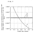
- a graph was prepared by enlarging the ordinate of Fig. 4 around 0 and enlarging the abscissa at elapsed times of 17 to 20 seconds (Fig. 7).
- the derivative signal dS1/dt of output signal of the photosensor 5 is in the predetermined range R1 expressed by formula (1) from an elapsed time of 17.69 seconds until an elapsed time of 18.71 seconds.
- the liquid mixture could not be determined as having been homogenized.
- the liquid mixture according to "d" was determined as not having been homogenized, because, as is clear from Fig.
- the output signal of the photosensor 5 at the point when homogenization was determined may be analyzed, as described above. Specifically, for “a”, the output signal of the photosensor 5 at the elapsed time of 16.29 seconds may be used, and for “b”, the output signal of the photosensor 5 at the elapsed time of 16.38 seconds may be used. Also, for “c”, the output signal of the photosensor 5 at the elapsed time of 16.42 seconds may be used. Accordingly, the optical property can be measured in a necessary and sufficient measurement time while the accuracy is assured, so that the measurement time can be reduced. Further, misoperations due to insufficient homogenization can be avoided.
- condition for determining homogenization is not limited to the above-described condition. That is, T, T1, and the predetermined range R expressed by formula (1) may be set as appropriate, according to various conditions such as the size of the fine particles, the density of the particle, the injection speed, the arrangement of the optical system, the accuracy required, the measurement time, the calibration curb, etc. Also, in calculating the concentration of a specific component of a test liquid, the computer 7 analyzes the output signal of the photosensor 5 at the point when homogenization was determined, while referring to the pre-set calibration curb, in order to calculate the concentration of the test liquid.
- the degree of stirring of the liquid mixture and homogenization can be determined with the sample cell mounted on the optical system. Further, since the time needed for a measurement is necessary and sufficient, time can be saved. Accordingly, while the process can be simplified, misoperations are unlikely to occur. These practical effects are extremely large, thereby making it possible to enhance the efficiency of measurements and tests and to achieve labor-savings thereof.
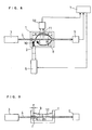
- FIGs. 8 and 9 Embodiment 2 of the present invention is described in detail below.
- the constituent elements represented by reference characters 1 to 10 are the same as the constituent elements represented by reference characters 1 to 10 in Figs. 1 and 2 used for describing the foregoing Embodiment 1, and they function in the same manner. It should be noted, however, that the light projected and scattered in a test liquid or a liquid mixture is detected in this embodiment.
- Scattered light 11 that arises while the substantially parallel light 4 is propagated through a test liquid is detected by a photosensor 12.
- the output signal of the photosensor 12 corresponds to the intensity of the scattered light 11 and is analyzed by the computer 7.
- the concentration of protein in a test liquid is measured, using a solution containing protein as the test liquid and a reagent liquid of sulfosalicylic acid (a reagent obtained by dissolving sodium sulfate in an aqueous solution of 2-hydroxy-5-sulfobenzoic acid) as the reagent liquid.
- a reagent liquid of sulfosalicylic acid a reagent obtained by dissolving sodium sulfate in an aqueous solution of 2-hydroxy-5-sulfobenzoic acid
- the protein component of the test liquid coagulates, thereby making the resultant whole liquid mixture turbid.
- the turbidity is measured as the intensity of scattered light, i.e., the output signal of the photosensor 12. The higher the protein concentration, the higher the turbidity, and the greater the output signal of the photosensor 12.
- the turbidity of a standard solution of a known concentration i.e., the output signal of the photosensor 12 is measured in advance, and based on this, a calibration curb is prepared. Then, the turbidity of a test liquid of an unknown concentration is measured, and the concentration is calculated by referring to the prepared calibration curb.
- the optical property i.e., the property change in turbidity
- the optical property is influenced not only by the stirring effect but also by the reaction (coagulation) property, unlike the foregoing Embodiment 1.
- an aqueous solution with a protein concentration of 100 mg/dl was introduced as a test liquid into the sample cell 1.
- the volume of the test liquid introduced was 0.25 ml.
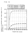
- the computer 7 was started to record the output signal of the photosensor 12. The changes over time in the output signal of the photosensor 12 after the start of the recording following the introduction are shown by ⁇ in Fig. 10.
- Fig. 10 the elapsed period of time since the start of measurement of the output signal is plotted in abscissa, and the output signal of the photosensor 12 is plotted in ordinate.
- the computer 7 controlled the pump 6 so that 0.05 ml of the reagent liquid of sulfosalicylic acid was injected from the injection port 2 over 2 seconds.
- the computer 7 analyzes the output signal of the photosensor 12 after the mixing of the reagent liquid represented by this solid line, while referring to the previously prepared calibration curb, in order to calculate the concentration of the test liquid.
- the homogenization by stirring proceeds in the same manner.
- the concentration was calculated, using a test liquid that required the longest period of time for the stabilization of the output signal. That is, in the case of a test liquid having a lowest protein concentration to be possibly detected, the output signal was measured at a point in time until which the output signal was expected to have been sufficiently stabilized, and the concentration of the test liquid was calculated using the measured output signal.
- a test liquid having a lowest protein concentration to be possibly detected
- the output signal was measured at a point in time until which the output signal was expected to have been sufficiently stabilized, and the concentration of the test liquid was calculated using the measured output signal.
- Such a method has a problem of requiring a long measurement time even if the measurement can be completed within a short period of time because of high reaction speed.
- the coagulated protein may start precipitating to cause a change in the intensity of scattered light, thereby impairing the accuracy. Also, since the reaction speed is dependent on temperature as well, there was a need to perform a measurement at a constant temperature.
- this embodiment describes the method of the present invention that not only calculates the concentration but also determines the completion of a reaction, based on the output signal of the photosensor 12.
- This embodiment can set the measurement time necessary and sufficient, thereby enabling a substantial increase in measurement speed.
- this embodiment needs no temperature control and can prevent a degradation in accuracy due to the precipitation phenomenon and the like. In such cases as described above, sufficient completion of a reaction (the stability of the output signal) is determined based on the optical property of the solution (the output signal of the photosensor 12).
- the maximum period of time within which a measurement is performed is set in advance. This period refers to the longest waiting period of time from the start of the measurement until obtaining the result, and if a measurement takes more than this maximum period of time, this measurement is rendered invalid.
- This pre-set period of time is referred to as a predetermined period of time T.
- homogenization is determined when the amount of change in an output signal S1 of the photosensor 12 per unit time, i.e., a derivative signal dS1/dt, has continuously been in a predetermined range R1 for a predetermined period of time T1 within the predetermined period of time T.
- homogenization is determined when dS1/dt [V/S] has continuously been in a predetermined range R1 represented by formula (2) for a predetermined period of time T1 (10 seconds) or longer within a predetermined period of time T (200 seconds) after the start of a measurement.
- T1 10 seconds
- T 200 seconds
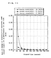
- Fig. 11 the derivative signal of output signal of the photosensor 12 was plotted in ordinate.
- ⁇ , ⁇ , and ⁇ of Fig. 11 correspond to the derivative signals represented by ⁇ , ⁇ , and ⁇ of Fig. 10, respectively.
- the flux of the injected reagent liquid itself entered the optical path of the substantially parallel light 4.
- the intensity of the scattered light was disturbed, causing a violent change in the output signal of the photosensor 12.
- ⁇ was omitted, since it looks like substantially zero.
- a graph was prepared as Fig. 12 by enlarging the ordinate of Fig. 11 around 0 and enlarging the abscissa at 60 to 200 seconds.
- Figs. 11 and 12 indicate that the derivative signal of output signal of the photosensor 12 was in the order of ⁇ > ⁇ > ⁇ immediately after the injection of the reagent liquid, but after an elapsed time of about 120 seconds, this sequence was totally reversed, so that the derivative signal was in the order of ⁇ > ⁇ > ⁇ . Then, all of ⁇ , ⁇ , and ⁇ asymptotically approached zero.
- a point of time when the derivative signal dS1/dt of output signal of the photosensor 12 has continuously been in the predetermined range R1 represented by formula (2) for the predetermined period of time T1 (10 seconds) or longer within the predetermined period of time T (200 seconds) after the start of a measurement was found from Fig. 12 as follows.
- the derivative signal dS1/dt of output signal of the photosensor 12 became 1 ⁇ 10 -4 [V/S] or less from an elapsed time of 77 seconds for ⁇ , from an elapsed time of 135 seconds for ⁇ , and from an elapsed time of 166 seconds for ⁇ . After these points in time, since ⁇ , ⁇ , and ⁇ asymptotically approached zero, the derivative signal was in the predetermined range R1 as expressed by formula (2).
- reaction completion could be determined at an elapsed time of 87 seconds.
- reaction completion could be determined at an elapsed time of 145 seconds.
- reaction completion could be determined at an elapsed time of 176 seconds.
- the output signal of the photosensor 12 at the point when the reaction completion was determined may be analyzed, as described above. Specifically, for ⁇ , the output signal of the photosensor 12 at the elapsed time of 87 seconds is used, and for ⁇ , the output signal of the photosensor 12 at the elapsed time of 145 seconds is used. For ⁇ , the output signal of the photosensor 12 at the elapsed time of 176 seconds is used. In preparing a calibration curb, the same condition as described above may be used for preparation.
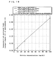
- Fig. 16 shows the dependency of the output signal of the photosensor 12 on the protein concentration.
- the solid line represents the output signal at an elapsed time of 200 seconds, and + represents the output signal at an elapsed time of 90 seconds.
- ⁇ represents the output signal at the point when the reaction completion was determined under the above condition, i.e., the output signal at the elapsed time of 176 seconds for 10 mg/dl, the output signal at the elapsed time of 145 seconds for 30 mg/dl, and the output signal at the elapsed time of 87 seconds for 100 mg/dl.
- the accuracy was retained at the respective concentrations; however, in the case of the output signal at the elapsed time of 90 seconds as represented by +, the lower the concentration, the lower the accuracy.
- the concentration can be measured in a necessary and sufficient measurement time while the accuracy is ensured, so that the measurement time can be shortened. Further, the degradation in accuracy due to insufficient completion of the reaction can be avoided.
- the condition for determining the completion of a reaction is not limited to the above-described condition. That is, T, T1, and the predetermined range R1 expressed by formula (2) may be set as appropriate, according to various conditions such as the kind of the reagent liquid, the injection speed, the arrangement of the optical system, the accuracy required, the measurement time, the calibration curb, etc. Also, in calculating the concentration of a specific component of a test liquid, the computer 7 analyzes the output signal of the photosensor 12 at the point when the reaction completion was determined, while referring to the pre-set calibration curb, in order to calculate the concentration of the test liquid. In preparing a calibration curb, the same condition as described above may be used for preparation. Also, it may be prepared by grasping the whole characteristics of changes over time in output signal responsive to standard solutions of known concentrations, which corresponds to Fig. 10, and using the output signal at the point when reaction completion was determined.
- the degree of reaction completion can be determined with the sample cell mounted on the optical system. Further, since the time needed for a measurement is necessary and sufficient, time can be saved. Accordingly, while the process can be simplified, misoperations are unlikely to occur. These practical effects are extremely large, thereby making it possible to enhance the efficiency of measurements and tests and to achieve labor-savings thereof.
- This embodiment has described an example in which the turbidity is measured by detecting, by means of the photosensor 12, the light that is scattered while the substantially parallel light 4 is propagated through the solution.
- the turbidity is measured as the intensity of transmitted light (the output signal of the photosensor 5)
- the same operations are also possible, and highly accurate measurements can be realized in the same manner.
- the reaction completion is determined using the intensity of transmitted light, T, T1, and the predetermined range R1 expressed by formula (2) may also be set as appropriate, according to various conditions such as the kind of the reagent liquid, the injection speed, the arrangement of the optical system, the accuracy required, the measurement time, the calibration curb, etc.
- the derivative signal of the output signal may be obtained with an analogue circuit, or, it may be obtained by measuring a plurality of times at appropriate intervals of time and performing differential analysis.
- the output signal monotonously increased or monotonously decreased.
- the methods according to the present invention are applicable in the same manner.
- dS1/dt was used as the evaluation index.
- S1 is relatively small, i.e., if the concentration of a test liquid is in a lower range, dS1/dt itself becomes small. Accordingly, in the case of a low concentration test liquid, the reaction may be mistakenly determined as having been completed even if the degree of reaction completion is low. Therefore, in this embodiment, the value obtained by dividing dS1/dt by the output signal S1, i.e., (dS1/dt)/S1, is used as the evaluation index to determine reaction completion.
- the maximum period of time within which a measurement is performed is set in advance. This period refers to the longest waiting period of time from the start of a measurement until obtaining the result, and if a measurement takes more than this maximum period of time, this measurement is rendered invalid.
- This pre-set period of time is referred to as a predetermined period of time T.
- homogenization is determined when the value obtained by dividing the amount of change in an output signal S1 of the photosensor 12 per unit time by the output signal S1, i.e., (dS1/dt)/S1, has continuously been in a predetermined range R2 for a predetermined period of time T2 within the predetermined period of time T.
- the liquid mixture is determined as having been homogenized when (dS1/dt)/S1 [V/S] has continuously been in a predetermined range R2 represented by formula (3) for a predetermined period of time T2 (10 seconds) or longer, within a predetermined period of time T (200 seconds) after the start of a measurement.
- T2 10 seconds
- T 200 seconds
- Fig. 13 the value obtained by dividing the derivative signal of output signal of the photosensor 12 by the output signal is plotted in ordinate.
- ⁇ , ⁇ , and ⁇ of Fig. 13 correspond to the values obtained by dividing the derivative signals represented by ⁇ , ⁇ , and ⁇ of Fig. 10, respectively, by the output signals.
- Fig. 13 in the same manner as in Fig. 10, during the period of about 2 seconds or more from the elapsed time of 20 seconds at which the injection of the reagent solution was started, the flux of the injected reagent liquid itself entered the optical path of the substantially parallel light 4, so that the intensity of scattered light was disturbed. As a result, (dS1/dt)/S1 changed violently.
- Fig. 13 in the same manner as in Fig. 10, during the period of about 2 seconds or more from the elapsed time of 20 seconds at which the injection of the reagent solution was started, the flux of the injected reagent liquid itself entered the optical path of the substantially parallel light 4, so that the intensity of
- Fig. 13 ⁇ was omitted, since it looks like substantially zero. Since the details of Fig. 13 are not readable, Fig. 14 was prepared by enlarging the ordinate around 0 and enlarging the abscissa around 60 to 200 seconds. Figs. 13 and 14 show that the derivative signal of output signal of the photosensor 12 was in the order of ⁇ > ⁇ > ⁇ immediately after the injection of the reagent liquid, and that they asymptotically approached zero.
- a point of time when the derivative signal dS1/dt/S1 has continuously been in the predetermined range R2 represented by formula (3) for the predetermined period of time T1 (10 seconds) or longer within the predetermined period of time T (200 seconds) after the start of a measurement was found from Fig. 14 as follows.
- the reaction could be determined as having been completed at an elapsed time of 79 seconds.
- the reaction could be determined as having been completed at an elapsed time of 158 seconds.
- this measurement was rendered invalid. Accordingly, as is clear from Fig. 16, when the protein concentration is 10 mg/dl, the accuracy is low, but such measurement could be rendered invalid. In the foregoing Embodiment 2, even when the accuracy is poor in such a low concentration range, the reaction is determined as having been completed, and such a measurement is rendered valid, so that the reliability of the measurement may be impaired. In this embodiment, however, by making such measurements invalid, the reliability can be secured.
- the concentration can be measured in a necessary and sufficient measurement time while the accuracy is ensured, so that the measurement time can be shortened. Further, it is possible to detect the degradation in accuracy due to relatively insufficient completion of the reaction which may occur when the test liquid is in a low concentration range, so that the reliability can be improved.
- condition for determining the completion of a reaction is not limited to the above-described condition. That is, T, T2, and the predetermined range R2 expressed by formula (3) may be set as appropriate, according to various conditions such as the kind of the reagent liquid, the injection speed, the arrangement of the optical system, the accuracy required, the measurement time, the calibration curb, etc.
- This embodiment uses the apparatus having the same structure as that illustrated in Figs. 8 and 9 used in the foregoing Embodiment 3, but employs a different method of determining the completion of a reaction.
- the output signal of the photosensor 12 as illustrated in Figs. 10 and 16 is used to calculate and determine the concentration.
- this embodiment also uses an output signal S0 of the photosensor 12 before the injection of the reagent liquid.
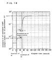
- Fig. 15 showed a graph in which the ordinate of Fig. 12 is expressed logarithmically.
- S1-S0 is used as an evaluation index. That is, (d(S1-S0)/dt)/(S1-S0) is used as the index.
- d(S1-S0)/dt dS1/dt holds, and whether or not (dS1/dt)/(S1-S0) is in a predetermined range R3 is evaluated.
- homogenization and/or reaction completion is determined when (dS1/dt)/(S1-S0) has been in the predetermined range R3 for a predetermined period of time T3 within a predetermined period of time T.
- this method is the same as that of Embodiment 3. Accordingly, it is possible to detect the relative degradation in accuracy in the case of using a low-concentration test liquid, as described in Embodiment 3, without being influenced by the turbidity of the test liquid before the injection of the reagent liquid.
- this embodiment can detect the degradation in accuracy due to relatively insufficient completion of the reaction which may occur in the case of a low-concentration-range test liquid, without being influenced by the turbidity of the test liquid itself, so that the reliability can be further improved.
- Fig. 17 Embodiment 5 of the present invention is described in detail below.
- the constituent elements represented by reference characters 1 to 12 are the same as the constituent elements represented by reference characters 1 to 12 in Fig. 8, and they function in the same manner.
- an injection port 13 is disposed in the side face of the sample cell 1 having no optical window and has an internal diameter (diameter) of 0.1 cm.
- a pump 14 injects a reagent liquid into a test liquid in the sample cell 1 from the injection port 13.
- an arrow 15 indicates the injection direction in which the reagent liquid is injected from the injection port 13.
- more than one kind of reagent liquid or the like is injected. For example, a buffer solution is first injected into the test liquid in the sample cell 1, and then, an antibody reagent liquid or the like is injected.
- the optical property of the liquid mixture is measured.
- the antibody reagent liquid which is a second reagent liquid, is injected, and after the completion of the reaction, the optical property of the liquid mixture is measured, to determine the concentration.
- urine samples having human serum albumin concentrations of 0.1 mg/dl, 0.3 mg/dl, 1.0 mg/dl, and 3.0 mg/dl were prepared by adding human serum albumin to urine from which human serum albumin was not detectable (substantially zero concentration).
- a 0.05 M MOPS buffer solution was prepared as the first reagent solution (R1).
- an antibody reagent liquid (R2) was prepared as the second reagent liquid by purifying the antibody component of antihuman albumin rabbit serum.
- each test liquid was introduced into the sample cell 1, at which point the photosensor 12 started measuring the intensity of scattered light (elapsed time of 0 seconds).
- the buffer solution serving as the first reagent solution (R1) was injected over 2 seconds.
- the first reagent liquid and the test liquid were determined as having been homogenized.
- the optical property of the liquid mixture was measured.
- the antibody reagent liquid serving as the second reagent liquid was injected over 2 seconds.
- the optical property of the liquid mixture was measured to obtain an output signal S0. Then, using the method described in any of the above-mentioned embodiments, the reaction associated with the second reagent liquid was determined as having been completed, and then the optical property of the liquid mixture was measured to obtain an output signal S1. It was confirmed that the difference between S0 and S1 thus obtained was proportional to the human serum albumin concentration of the test liquid.
- each reagent liquid is injected, and after the lapse of a predetermined period of time from the point of the determination of homogenization or reaction completion, the next reagent liquid is injected.
- the optical property is measured if necessary, and the concentration is calculated based on the measured value.
- the optical property is measured after determining homogenization and/or reaction completion following the injection of each reagent liquid, and thereafter, the next reagent liquid is injected. Therefore, the respective impacts of the reagent liquids can be distinguished in making measurements, thereby resulting in high reliability.
- the turbidity may be measured by mixing the test liquid and a buffer solution in advance and then mixing an antibody reagent liquid.
- the turbidity due to the antibody-antigen combination which is a specific binding reaction, can be distinguished from the turbidity of the test liquid itself and the turbidity resulting from the mixing of the test liquid and the buffer solution in making measurements. Accordingly, only the specific antigen can be specifically detected, and hence, the reliability of measurements can be ensured.
- the predetermined period of time T4 is zero or more, and that it may be any period of time during which the optical property can be measured.
- the present invention needs only a period of time necessary for homogenization and/or completion of a reaction. That is, the invention only requires that the necessary condition be satisfied with respect to the measurement time. Therefore, the measurement time can be shortened, which is highly practically effective, and more efficient and labor-saving measurements and tests become possible. Further, since measurements with poor accuracy can be rendered invalid, the reliability is high. Also, the concentration can be measured by specifically detecting only a specific component of a test liquid, which is greatly practically effective.
- the invention is applicable to, for example, urinalysis.
Landscapes
- Chemical & Material Sciences (AREA)
- Physics & Mathematics (AREA)
- Immunology (AREA)
- Pathology (AREA)
- Analytical Chemistry (AREA)
- Biochemistry (AREA)
- General Health & Medical Sciences (AREA)
- General Physics & Mathematics (AREA)
- Health & Medical Sciences (AREA)
- Life Sciences & Earth Sciences (AREA)
- Chemical Kinetics & Catalysis (AREA)
- Engineering & Computer Science (AREA)
- Plasma & Fusion (AREA)
- Mathematical Physics (AREA)
- Theoretical Computer Science (AREA)
- Spectroscopy & Molecular Physics (AREA)
- Investigating Or Analysing Materials By The Use Of Chemical Reactions (AREA)
- Investigating Or Analysing Materials By Optical Means (AREA)
Abstract
It is intended to provide a method for determining homogenization and/or reaction completion, capable of making the measurement time necessary and sufficient and enhancing the measurement speed, and a method for measuring solution concentration using the same. According to the method for determining homogenization and/or reaction completion and the method for measuring solution concentration using the same, homogenization and reaction completion are determined based on the optical property of the liquid mixture of a test liquid and a reagent liquid. <IMAGE>
Description
The present invention relates to solution
concentration measuring methods and solution concentration
measuring apparatuses for determining the concentration of a
solute dissolved in a test liquid, for example, protein. More
specifically, the present invention measures the concentration
of a specific component contained in a test liquid, by mixing
a reagent liquid into the test liquid to change the optical
property of the test liquid deriving from only the specific
component. Particularly, by mixing the test liquid and the
reagent liquid to coagulate the protein component, and
detecting the decrease in light transmitted through the test
liquid after the mixing and/or the increase in the intensity
of light scattered during the propagation through the test
liquid, the present invention measures the concentration of
this protein component.
The present invention determines that the test
liquid and the reagent liquid have been sufficiently stirred
until homogenized, when the relation between the elapsed
period of time since the mixing and the intensity of light
transmitted through the liquid mixture or the intensity of
scattered light satisfies a predetermined condition. Also, by
this, the present invention can simultaneously determine that
the reaction between the test liquid and the reagent liquid
has been completed. In this way, by determining
homogenization and/or reaction completion, it is possible to
set the measurement time necessary and sufficient, and to
reduce the measurement time. In the case of not controlling
the temperature of the liquid mixture of the test liquid and
the reagent liquid, in particular, the present invention can
realize high reliability with a necessary and sufficient
measurement time and provide highly practical methods for
measuring solution concentration.
According to conventional methods of measuring
solution concentration, a test liquid and a reagent liquid are
mixed in a predetermined volume ratio and sufficiently stirred
until the resultant mixture becomes homogeneous, to prepare a
liquid mixture. Then, the liquid mixture is stirred at a
predetermined temperature, and upon the lapse of a
predetermined period of time, the optical property of the
liquid mixture is measured to determine the concentration. In
methods of measuring the concentration of a specific component
by utilizing biochemical reactions, such as enzyme reactions
and antigen-antibody reactions, it is common to set the
predetermined temperature to 37 °C, which is close to living
body temperature. It is also common to set the predetermined
period of time to a period of time within which the reaction
sufficiently reaches completion. Naturally, since the rate of
a reaction depends on temperature, concentration, and the like,
a sufficient period of time for the completion of the reaction
is set in consideration of the concentration of the test
liquid at the predetermined temperature.
As described above, in conventional practice,
optical property is measured under conditions where the liquid
mixture is sufficiently stirred until homogenized and the
reaction would never fail to reach completion. That is,
sufficient conditions for homogenization and reaction
completion are set.
Also, with conventional apparatuses for measuring
solution concentration, a test liquid is retained in a sample
cell that is structured to propagate light through the test
liquid. This sample cell is in the form of a rectangular
parallelepiped, made of, for example, glass, and has
transmission faces that are transparent. Thus, light can be
propagated through the test liquid. When the test liquid and
a reagent liquid are introduced into the sample cell and mixed,
the sample cell is detached from the optical system for
measuring optical property, and the following operations are
performed.
Usually, the top part of this sample cell is open,
and a predetermined volume of a test liquid is introduced from
the top part using a dropper, a pipette, a syringe, or the
like. Subsequently, a predetermined volume of a reagent
liquid is mixed thereinto such that the volume ratio of the
test liquid to the reagent liquid is constant. Thereafter,
the resultant mixture is sufficiently stirred in the sample
cell with a stirring stick, stirrer, or the like until it
becomes homogenized, and the whole sample cell is kept at a
predetermined temperature, for example, in a constant-temperature
bath. After the lapse of a predetermined period
of time, the sample cell is remounted onto the optical system,
and the optical property of the liquid mixture in the sample
cell is measured.
However, there have been problems in that
conventional solution concentration measuring methods involve
a large number of processes and conventional solution
concentration measuring apparatuses are large-scaled. Further,
there has been another problem of requiring increased
measurement time. Therefore, there is a demand for solution
concentration measuring apparatuses having a simple structure
without a constant-temperature bath and the like, as well as
solution concentration measuring methods capable of easy
automation.
Further, there has also been another problem in that
the processes of loading and unloading the sample cell cause a
slight change in the position of the optical system, possibly
leading to errors in measurement results. Furthermore, still
another problem has been that complicated operations are
necessary, and hence, operation mistakes, etc. tend to occur,
thereby resulting in poor reliability.
In consideration of the above-mentioned problems, an
object of the present invention is to provide a highly
reliable method of measuring solution concentration capable of
easy automation, as well as a highly reliable, small-sized
apparatus of measuring solution concentration capable of easy
automation. The present invention further provides a solution
concentration measuring method and a solution concentration
measuring apparatus which can reduce the time necessary for
homogenization and/or reaction completion to the requisite
minimum, thereby enabling a reduction in measurement time.
The present invention relates to a method for
determining homogenization and/or reaction completion,
including the steps of: (1) mixing a test liquid and a reagent
liquid to obtain a liquid mixture; (2) measuring an optical
property of the liquid mixture after the mixing continuously
or a plurality of times discretely; (3) obtaining a relation
between the measured value of the optical property obtained
and the elapsed period of time since the start of the
measurement after the mixing; and (4) determining, on the
basis of the relation, whether the test liquid and the reagent
liquid have been substantially homogeneously mixed with each
other and/or a reaction between the test liquid and the
reagent liquid has been substantially completed. The steps
(1) to (4) are performed in this order.
In this method for determining homogenization and/or
reaction completion, the step (3) is preferably a step of
obtaining dS1/dt (wherein S1 is the measured value of the
optical property obtained and T is the elapsed period of time
since the start of the measurement after the mixing), and the
step (4) is preferably a step of determining that the test
liquid and the reagent liquid have been substantially
homogeneously mixed with each other and/or the reaction
between the test liquid and the reagent liquid has been
substantially completed, when the dS1/dt has continuously been
in a predetermined range R1 for a predetermined period of time
T1 or longer.
Also, the step (3) is preferably a step of obtaining
(dS1/dt)/S1 (wherein S1 is the measured value of the optical
property obtained and T is the elapsed period of time since
the start of the measurement after the mixing), and the step
(4) is preferably a step of determining that the test liquid
and the reagent liquid have been substantially homogeneously
mixed with each other and/or the reaction between the test
liquid and the reagent liquid has been substantially completed,
when the (dS1/dt)/S1 has continuously been in a predetermined
range R2 for a predetermined period of time T2 or longer.
Further, the present invention pertains to a method
for determining homogenization and/or reaction completion,
including the steps of: (1) mixing a test liquid and a reagent
liquid to obtain a liquid mixture; (2) measuring an optical
property of the test liquid and the liquid mixture
continuously, or, measuring an optical property of the test
liquid at least once and measuring an optical property of the
liquid mixture after the mixing a plurality of times
discretely; (3) obtaining a relation between the measured
value of the optical property obtained and the elapsed period
of time since the start of the measurement after the mixing;
and (4) determining, on the basis of the relation, that the
test liquid and the reagent liquid have been substantially
homogeneously mixed with each other and/or the reaction
between the test liquid and the reagent liquid has been
substantially completed. The steps (1) to (4) are performed
in this order.
In the method for determining homogenization and/or
reaction completion, the step (3) is preferably a step of
obtaining (dS1/dt)/(S1-S0) (wherein S0 is the measured value
of the optical property of the test liquid, S1 is the measured
value of the optical property of the liquid mixture, and T is
the elapsed period of time since the start of the measurement
after the mixing), and the step (4) is preferably a step of
determining that the test liquid and the reagent liquid have
been substantially homogeneously mixed with each other and/or
the reaction between the test liquid and the reagent liquid
has been substantially completed, when the (dS1/dt)/(S1-S0)
has continuously been in a predetermined range R3 for a
predetermined period of time T3 or longer.
Furthermore, the present invention is directed to a
method for measuring solution concentration, wherein the
homogenization of the mixture of the test liquid and the
reagent liquid and/or the substantial completion of the
reaction therebetween are determined according to the above-mentioned
method for determining homogenization and/or
reaction completion, and then the concentration of a specific
component of the test liquid is determined based on the
measured value S1 or the measured values of S0 and S1.
This method for measuring solution concentration
preferably includes the step of mixing another reagent liquid
with the test liquid, after determining that the test liquid
and the reagent liquid have been homogeneously mixed and/or
the reaction therebetween has been substantially completed.
In this case, preferably, another reagent liquid is
mixed with the test liquid upon the lapse of a predetermined
period of time T4 after determining that the test liquid and
the reagent liquid have been homogeneously mixed and/or the
reaction therebetween has been substantially completed, and
the optical property of the liquid mixture is measured prior
to the lapse of the predetermined period of time T4.
The present invention also relates to an apparatus
for measuring solution concentration, including: a light
source that irradiates a test liquid with light; a sample cell
that retains the test liquid; a photosensor 1 that detects
light transmitted through the test liquid and/or a photosensor
2 that detects light scattered while the light is propagated
through the test liquid; and a computer that analyzes an
output signal of the photosensor 1 and/or the photosensor 2,
wherein based on the above-mentioned method for measuring
solution concentration, the computer analyzes the output
signal of the pohotosensor 1 and/or the photosensor 2 to
calculate the concentration of the test liquid.
That is, the computer preferably includes
controlling means for measuring an optical property of the
liquid mixture obtained by mixing a test liquid and a reagent
liquid continuously or a plurality of times discretely,
obtaining a relation between the measured value of the optical
property obtained and the elapsed period of time since the
start of the measurement after the mixing, determining, on the
basis of the relation, that the test liquid and the reagent
liquid have been substantially homogeneously mixed with each
other and/or a reaction between the test liquid and the
reagent liquid has been substantially completed, and
determining the concentration of a specific component in the
test liquid based on the measured value.
Also, the controlling means of the computer may
measure the optical property of the test liquid and the liquid
mixture continuously, or, it may measure the optical property
of the test liquid at least once and measure the optical
property of the liquid mixture after the mixing a plurality of
times discretely.
Further, it is preferred that the apparatus for
measuring solution concentration include an injector that
injects a reagent liquid into the test liquid in the sample
cell for mixing and that the injector be controlled by the
computer or the controlling means.
In the apparatus for measuring solution
concentration, it is preferred that the optical property of
the test liquid be measured, using the light source, to
determine the concentration of a specific component in the
test liquid.
It is also preferred to perform stirring by means of
the mechanical effect produced by the injection of the reagent
liquid.
Further, in the above-mentioned method for
determining homogenization and/or reaction completion, method
for measuring solution concentration, and apparatus for
measuring solution concentration, it is preferred that a
measurement be rendered invalid when homogenization and/or
reaction completion has not been determined within a
predetermined period of time T from the start of the
measurement.
It is also preferred that when the concentration of
the analyte in the test liquid is the lowest possible
concentration, the above-mentioned predetermined period of
time T satisfy the relation T ≧ T5 wherein T5 is the elapsed
period of time since the start of a measurement until
homogenization or reaction completion is determined by the
above-mentioned method for determining homogenization and/or
reaction completion.
It is also preferred that the substance that reacts
with the analyte be an antibody that specifically reacts and
combines with the analyte and that the signal related to the
optical property that derives from the specific binding
reaction be the turbidity of the liquid mixture.
It is further preferred that the analyte be human
albumin.
The present invention relates to a solution
concentration measuring method that qualitatively or
quantitatively determines an analyte, by mixing a test liquid
containing the analyte with a reagent liquid containing a
substance that reacts with the analyte, and detecting a signal
related to the optical property deriving from the reaction.
The present invention relates to a method for
determining homogenization and/or reaction completion,
including the steps of: (1) mixing a test liquid and a reagent
liquid to obtain a liquid mixture; (2) measuring an optical
property of the liquid mixture after the mixing continuously
or a plurality of times discretely, or, measuring an optical
property of the test liquid and the liquid mixture
continuously, or, measuring an optical property of the test
liquid at least once and measuring an optical property of the
liquid mixture after the mixing a plurality of times
discretely; (3) obtaining a relation between the measured
value of the optical property obtained and the elapsed period
of time since the start of the measurement after the mixing;
and (4) determining, on the basis of the relation, whether the
test liquid and the reagent liquid have been substantially
homogeneously mixed with each other and/or a reaction between
the test liquid and the reagent liquid has been substantially
completed.
The present invention also provide a solution
concentration measuring method and a solution concentration
measuring apparatus using this method for measuring
homogenization and/or reaction completion.
Referring now to drawings, various embodiments of
the present invention are described below.
Referring to Figs. 1 and 2, Embodiment 1 of the
present invention is detailed below. Fig. 1 is a top view of
a solution concentration measuring apparatus according to
Embodiment 1 of the present invention. Fig. 2 is a partially
cross-sectional side view of the solution concentration
measuring apparatus according to Embodiment 1 of the present
invention. In Figs. 1 and 2, the skeletal part of a sample
cell 1 is composed of an aluminum container that is in the
form of a rectangular parallelepiped and has an opening at the
top. A glass plate, serving as an optical window, is fitted
into a pair of side faces of the sample cell 1 to form an
optical path, so that light can be transmitted through a test
liquid (or a liquid mixture of a test liquid and a reagent
liquid) retained in the sample cell 1. In Fig. 1, the
distance between the optical windows (optical length), which
is the distance in the direction of light propagation in the
sample cell 1, is represented by A, and the distance in the
direction perpendicular to the direction of light propagation
in the sample cell 1 is represented by B. In this embodiment,
A and B are set to 0.8 cm and 0.4 cm, respectively, as a
representative example to explain the present invention.
As illustrated in Fig. 1, an injection port 2 is
provided in the edge of the side face of the sample cell 1
having no optical window, and the internal diameter (diameter)
of the injection port 2 is 0.1 cm. As illustrated in Fig. 2,
the center of the vertical section of the injection port 2 is
positioned at a distance x from the bottom face of the sample
cell 1 and at a distance z from the optical window. Injection
direction 10 is parallel to the faces having the optical
windows and perpendicular to the direction of light
propagation. In this embodiment, x and y are set to 0.4 cm
and 0.1 cm, respectively, as a representative example to
explain the present invention.
A semiconductor laser module 3, which is a light
source, projects substantially parallel light 4 onto the test
liquid in the sample cell. The substantially parallel light 4
has a wavelength of 780 nm, an intensity of 3.0 mW, and a beam
diameter of 0.2 cm. The optical axis of this substantially
parallel light 4 is parallel to the bottom face of the sample
cell 1 and positioned at a distance of 0.4 cm from the bottom
face. Therefore, the optical axis and the injection port 2
are positioned at the same height from the bottom face, and
the optical axis of the substantially parallel light 4 and the
injection axis extending from the center of the section of the
injection port 2 in the injection direction 10 have a point of
intersection in the solution in the sample cell 1.
A photosensor 5 is a photosensor which detects light
that has been transmitted through the test liquid. A pump 6
injects a reagent liquid from the injection port 2 into the
test liquid in the sample cell 1. A computer 7 analyzes the
output signal of the photosensor 5 and controls the pump 6.
An arrow 8 schematically indicates the direction of the vortex
that occurs in the sample cell 1 when the reagent liquid is
injected from the injection port 2. Also, the lowest part of
liquid level 9 of the test liquid is positioned at a height h
from the bottom face of the sample cell 1. In the present
invention, the liquid level is defined as the level that is in
contact with the lowest part of the liquid level 9 and
parallel to the horizontal level. According to this
definition, the injection direction is parallel to the liquid
level in this embodiment.
The sample cell 1 has inner wall corners that are
rounded. That is, the corners of the sample cell 1 are not
right-angled in a strict sense. Thus, when h = 0.8 cm, the
sample cell 1 contains about 0.25 ml of the test liquid.
In this embodiment, a dispersion obtained by
homogeneously dispersing polystyrene fine particles having a
mean diameter of 20 nm in pure water is charged into the
sample cell 1 as the test liquid. The whole test liquid is
homogeneously turbid.
First, the mechanism of injecting pure water into
this test liquid is described. The polystyrene fine particles
have a specific gravity close to that of pure water, and their
particle size is also small. Thus, once they have been fully
homogeneously dispersed in pure water, phenomena such as
separation and precipitation do not occur during the period of
time in which the method according to the present invention is
carried out. However, if they have not been homogeneously
dispersed due to insufficient stirring, such phenomena may
occur.
When pure water is injected into this test liquid,
the polystyrene fine particles diffuse therethrough, so that
the concentration of the polystyrene fine particles lowers.
Consequently, the degree of opacity of the whole test liquid,
i.e., turbidity, lowers. This turbidity is measured as the
intensity of transmitted light by detecting the output signal
of the photosensor 5.
In this way, the change in the turbidity of the
liquid containing fine particles due to diffusion involves no
chemical reaction. Therefore, the turbidity of the whole test
liquid depends solely on the degree of diffusion of the
polystyrene fine particles, and hence, there is no need to
take reaction speed into consideration. That is, the fact
that the turbidity has been stabilized at a certain value
means that the fine particles have been sufficiently spread
throughout the liquid and homogeneously dispersed.
From these, observing the turbidity by mixing a
liquid containing fine particles as a reagent liquid with a
test liquid is convenient in verifying the stirring effect.
In this embodiment, the present invention is simplified for
the purpose of explanation by selecting only the result of
determination of the homogenization attained by the stirring
of the present invention.
The operations of this embodiment were conducted as
follows:
First, the test liquid containing the polystyrene
fine particles was introduced into the sample cell 1. At this
time, the volume of the test liquid introduced was 0.25 ml.
The computer 7 was started to measure (record) the output
signal of the photosensor 5. The changes over time in the
output signal of the photosensor 5 after the start of the
measurement following the introduction are shown in Fig. 3.
In Fig. 3, the elapsed period of time since the
start of measurement of the output signal is plotted in
abscissa, and the output signal of the photosensor 5 is
plotted in ordinate. At an elapsed time of 10 seconds, the
computer 7 controlled the pump 6 so that pure water was
injected from the injection port 2 over 2 seconds. The
changes in the output signal of the photosensor 5 in the case
of pure water injection, as described, are shown by solid
lines in Fig. 3. In Fig. 3, "a", "b", "c", and "d" show the
changes in the output signal of the photosensor 5 resulting
from the injection of 0.1 ml of pure water, 0.07 ml of pure
water, 0.05 ml of water, and 0.03 ml of pure water,
respectively.
In this figure, for 2 to 3 seconds from the start of
the pure water injection, i.e., the elapsed time of 10 seconds
since the start of the recording, the flux of the injected
pure water itself entered the optical path of the
substantially parallel light 4. As a result, the intensity
and the propagation direction of transmitted light were
disturbed, causing a violent change in the output signal of
the photosensor 5. In Fig. 3, the amplitude of the change is
illustrated as the hatched area, and the output signal changed
between 0.6 to 1.4 V. Even when the same volume of pure water
was injected, the amplitude of the change was shown in this
area, though the details of the change were not confirmed.
Since the concentration of the polystyrene particles lowered
depending on the amount of pure water injected, the turbidity
also decreased depending on the amount of injection.
When the injected amounts of pure water were 0.1 ml,
0.07 ml, and 0.05 ml, as shown by the solid lines "a", "b",
and "c" of Fig. 3, respectively, the resultant output signals
were commensurate with the respective amounts of injection,
and the output signals themselves were stabilized. This is
because the injection of pure water produced a vortex in the
test liquid, which allowed the liquid mixture of the test
liquid and the pure water to be sufficiently stirred until it
became homogenized. The homogenization could also be
confirmed by visual observation. On the other hand, when the
amount of injection was 0.03 ml, the output signal was not
stabilized, as shown by the solid line "d". This is because
the liquid mixture of the test liquid and the pure water was
stirred insufficiently and was not stirred until homogenized.
The inconsistencies in the concentration of the polystyrene
fine particles could also be confirmed by visual observation.
As described above, the solid lines "a" to "c"
represented the cases where the liquid mixture of the test
liquid and the pure water was sufficiently stirred until
homogenized, while the solid line "d" represented the case
where the liquid mixture could not be sufficiently stirred
until homogenized.
Conventionally, in measuring the optical property of
a test liquid, such as turbidity, from the output signal of
the photosensor 5, one had to wait for the lapse of a period
of time within which the output signal of the photosensor 5
became sufficiently stabilized. After the lapse of that
period of time, one analyzed the output signal of the
photosensor 5. For example, the output signal of the
photosensor 5 at an elapsed time of 60 seconds since the start
of the recording was used. In the case of the solid line "d"
according to the present invention, however, an accurate
measurement of the optical property was not possible, because
the liquid mixture had not been homogenized. Hence, there was
a need to additionally make visual observations to confirm the
homogenization.
Contrary to such conventional art, the method of the
present invention, which will be described below, determines
whether or not the liquid mixture has been sufficiently
stirred, i.e., whether or not the liquid mixture has become
homogenized, based on the optical property of the liquid
mixture, i.e., the output signal of the photosensor 5.
Summing up, this method is an example of being able to reduce
the measurement time by setting the waiting time from the
start of a measurement until obtaining the result necessary
and sufficient.
First, the maximum period of time within which a
measurement is performed is set in advance. This period
refers to the longest waiting period of time from the start of
the measurement until obtaining the result, and if a
measurement takes more than this maximum period of time, this
measurement is rendered invalid. This pre-set period of time
is referred to as a predetermined period of time T.
According to this method, homogenization is
determined when the amount of change in an output signal S1 of
the photosensor 5 per unit time, i.e., a derivative signal
dS1/dt, has continuously been in a predetermined range R1 for
a predetermined period of time T1 within the predetermined
period of time T.
Specifically, the liquid mixture is determined as
having been homogenized when dS1/dt [V/S] has continuously
been in a predetermined range R1 represented by formula (1)
for a predetermined period of time T1 (1.5 seconds) or longer
within a predetermined period of time T (60 seconds) after the
start of a measurement.
-5 × 10⁻⁴ ≦ dS1/dt ≦ 5 × 10⁻⁴
It should be noted that if the predetermined period of time T,
which corresponds to the longest waiting period of time, is
not properly set, the derivative signal dS1/dt may be in the
predetermined range R1 for the predetermined period of time T1,
even if the liquid mixture has not been homogenized due to
insufficient stirring, particularly even if pure water regions
are separated from fine particle regions. Thus, there is a
possibility of making a wrong determination that the liquid
mixture has been homogenized.
Fig. 4 shows the derivative signal of output signal
of the photosensor 5. The solid lines "a" to "d" of Fig. 3
correspond to the derivative values (dS/dt) of the signal
intensities represented by the solid lines "a" to "c" and the
dotted line "d" of Fig. 4, respectively. In Fig. 4, in the
same manner as in Fig. 3, during the period of about 2 seconds
or more from the elapsed time of 10 seconds at which the
injection of pure water was started, the flux of the injected
pure water itself entered the optical path of the
substantially parallel light 4. As a result, the intensity
and the propagation direction of transmitted light were
disturbed, causing a violent change in the derivative signal
of output signal of the photosensor 5. In Fig. 4, the solid
lines "a" to "c" appeared to coincide with one another. Thus,
a graph was prepared by enlarging the ordinate of Fig. 4
around 0 (Fig. 5). Fig. 5 showed that the solid lines "a" to
"c" asymptotically approached zero, and that the broken line
"d" largely swayed toward the minus side before going through
the minimum value. However, in Fig. 5, the solid lines "a" to
"c" also appeared to coincide with one another.
Thus, Fig. 6 showed a graph obtained by enlarging
the ordinate at zero and greater and enlarging the abscissa
around 14.5 to 16.5 seconds in Fig. 4. In Fig. 6, ▴
corresponds to "a", ▪ corresponds to "b", and corresponds to
"c". As is clear from Fig. 6, "a" to "c" asymptotically
approached zero.
For the condition for determining homogenization, a
point of time when the derivative signal dS1/dt of output
signal of the photosensor 5 has continuously been in the
predetermined range R1 represented by formula (1) for the
predetermined period of time T1 (1.5 seconds) or longer within
the predetermined period of time T (60 seconds) after the
start of a measurement was found as follows.
The derivative signal dS1/dt of output signal of the
photosensor 5 became 5 × 10⁻⁴ [V/S] or less from an elapsed
time of 14.79 seconds for "a", from an elapsed time of 14.88
seconds for "b", and from an elapsed time of 14.92 seconds for
"c". After these points in time, since "a" to "c"
asymptotically approached zero, the derivative signal was in
the predetermined range R1 as expressed by formula (1).
Therefore, in Fig. 6, if the point of the lapse of
1.5 seconds from the point when the derivative signal dS/dt
fell within the predetermined range R1 expressed by formula
(1) is within the predetermined period of time (T = 60
seconds) from the start of the measurement, the liquid mixture
could be determined as having been homogenized at an elapsed
time of 15 seconds. Specifically, for "a", homogenization
could be determined at an elapsed time of 16.29 seconds. For
"b", homogenization could be determined at an elapsed time of
16.38 seconds. For "c", homogenization could be determined at
an elapsed time of 16.42 seconds.
Meanwhile, a graph was prepared by enlarging the
ordinate of Fig. 4 around 0 and enlarging the abscissa at
elapsed times of 17 to 20 seconds (Fig. 7). As shown in Fig.
7, the derivative signal dS1/dt of output signal of the
photosensor 5 is in the predetermined range R1 expressed by
formula (1) from an elapsed time of 17.69 seconds until an
elapsed time of 18.71 seconds. In this case, since the
derivative signal was within the R1 only for 1.02 seconds (=
18.71 - 17.69), the liquid mixture could not be determined as
having been homogenized. Also, the liquid mixture according
to "d" was determined as not having been homogenized, because,
as is clear from Fig. 5, the derivative signal does not fall
within the range R1 at least until the point of the lapse of
the predetermined period of time (T = 60 seconds) after the
start of the measurement. By using such determination
condition, it was possible to adequately determine whether or
not the liquid mixture had been sufficiently stirred and
homogenized.
In measuring the optical property of a test liquid,
such as turbidity, from the output signal of the photosensor 5,
the output signal of the photosensor 5 at the point when
homogenization was determined may be analyzed, as described
above. Specifically, for "a", the output signal of the
photosensor 5 at the elapsed time of 16.29 seconds may be used,
and for "b", the output signal of the photosensor 5 at the
elapsed time of 16.38 seconds may be used. Also, for "c", the
output signal of the photosensor 5 at the elapsed time of
16.42 seconds may be used. Accordingly, the optical property
can be measured in a necessary and sufficient measurement time
while the accuracy is assured, so that the measurement time
can be reduced. Further, misoperations due to insufficient
homogenization can be avoided.
It is needless to say that the condition for
determining homogenization is not limited to the above-described
condition. That is, T, T1, and the predetermined
range R expressed by formula (1) may be set as appropriate,
according to various conditions such as the size of the fine
particles, the density of the particle, the injection speed,
the arrangement of the optical system, the accuracy required,
the measurement time, the calibration curb, etc. Also, in
calculating the concentration of a specific component of a
test liquid, the computer 7 analyzes the output signal of the
photosensor 5 at the point when homogenization was determined,
while referring to the pre-set calibration curb, in order to
calculate the concentration of the test liquid.
As described above, according to this embodiment,
the degree of stirring of the liquid mixture and
homogenization can be determined with the sample cell mounted
on the optical system. Further, since the time needed for a
measurement is necessary and sufficient, time can be saved.
Accordingly, while the process can be simplified,
misoperations are unlikely to occur. These practical effects
are extremely large, thereby making it possible to enhance the
efficiency of measurements and tests and to achieve labor-savings
thereof.
Referring now to Figs. 8 and 9, Embodiment 2 of the
present invention is described in detail below. In Figs. 8
and 9, the constituent elements represented by reference
characters 1 to 10 are the same as the constituent elements
represented by reference characters 1 to 10 in Figs. 1 and 2
used for describing the foregoing Embodiment 1, and they
function in the same manner. It should be noted, however,
that the light projected and scattered in a test liquid or a
liquid mixture is detected in this embodiment.
Scattered light 11 that arises while the
substantially parallel light 4 is propagated through a test
liquid is detected by a photosensor 12. The output signal of
the photosensor 12 corresponds to the intensity of the
scattered light 11 and is analyzed by the computer 7.
In this embodiment, the concentration of protein in
a test liquid is measured, using a solution containing protein
as the test liquid and a reagent liquid of sulfosalicylic acid
(a reagent obtained by dissolving sodium sulfate in an aqueous
solution of 2-hydroxy-5-sulfobenzoic acid) as the reagent
liquid. In this case, when the test liquid and the reagent
liquid of sulfosalicylic acid are mixed together, the protein
component of the test liquid coagulates, thereby making the
resultant whole liquid mixture turbid. Thus, by measuring the
degree of opacity, i.e., turbidity, the protein concentration
can be determined. The turbidity is measured as the intensity
of scattered light, i.e., the output signal of the photosensor
12. The higher the protein concentration, the higher the
turbidity, and the greater the output signal of the
photosensor 12.
In calculating the protein concentration, the
turbidity of a standard solution of a known concentration,
i.e., the output signal of the photosensor 12, is measured in
advance, and based on this, a calibration curb is prepared.
Then, the turbidity of a test liquid of an unknown
concentration is measured, and the concentration is calculated
by referring to the prepared calibration curb.
In this embodiment, the optical property, i.e., the
property change in turbidity, is influenced not only by the
stirring effect but also by the reaction (coagulation)
property, unlike the foregoing Embodiment 1.
The operations of this embodiment were performed as
follows:
First, an aqueous solution with a protein
concentration of 100 mg/dl was introduced as a test liquid
into the sample cell 1. At this time, the volume of the test
liquid introduced was 0.25 ml. The computer 7 was started to
record the output signal of the photosensor 12. The changes
over time in the output signal of the photosensor 12 after the
start of the recording following the introduction are shown by
in Fig. 10.
In Fig. 10, the elapsed period of time since the
start of measurement of the output signal is plotted in
abscissa, and the output signal of the photosensor 12 is
plotted in ordinate. At an elapsed time of 20 seconds since
the start of the measurement, the computer 7 controlled the
pump 6 so that 0.05 ml of the reagent liquid of sulfosalicylic
acid was injected from the injection port 2 over 2 seconds.
Likewise, 0.25 ml of an aqueous solution with a
protein concentration of 30 mg/dl, 10 mg/dl, or 0 mg/dl was
introduced into the sample cell 1. At an elapsed time of 20
seconds since the start of the measurement, 0.05 ml of the
reagent liquid of sulfosalicylic acid was injected. The
output signals of the photosensor 12 for the aqueous solutions
having the concentrations of 30 mg/dl, 10 mg/dl, and 0 mg/dl,
respectively, are shown by ▪, ×, and ○ in Fig. 10.
In Fig. 10, the output signals as shown by , ▪, ×,
and ○ changed largely near the point when the reagent liquid
was injected, and this was attributed to the invasion of the
flux of the injected reagent liquid itself on the optical path
of the substantially parallel light 4. This was because the
refractive index of the protein aqueous solution, which is a
test liquid, is different from that of the aqueous solution of
sulfosalicylic acid, and hence, the resultant local unevenness
caused a large change in the intensity of the scattered light.
Further, this was also because the injection caused fine
particles such as bubbles to enter the optical path, thereby
causing a large change in the intensity of the scattered light.
The region of this large change was shown by hatching. From
the start of the measurement until the elapsed time of 20
seconds at which the injection was started, all of the
respective solid lines and the dotted line coincided with one
another, so this period was illustrated as only one solid line.
In calculating the concentration of a specific
component of a test liquid, the computer 7 analyzes the output
signal of the photosensor 12 after the mixing of the reagent
liquid represented by this solid line, while referring to the
previously prepared calibration curb, in order to calculate
the concentration of the test liquid. In the above operations,
since the same volume of the reagent liquid is injected into
the same volumes of the test liquids over the same period of
time, the homogenization by stirring proceeds in the same
manner. However, as is clear from Fig. 10, it takes a
different period of time for each output signal to reach
saturation, i.e., to become stabilized. This is because the
reaction speed is different according to the protein
concentration.
In such cases, conventionally, the concentration was
calculated, using a test liquid that required the longest
period of time for the stabilization of the output signal.
That is, in the case of a test liquid having a lowest protein
concentration to be possibly detected, the output signal was
measured at a point in time until which the output signal was
expected to have been sufficiently stabilized, and the
concentration of the test liquid was calculated using the
measured output signal. Such a method has a problem of
requiring a long measurement time even if the measurement can
be completed within a short period of time because of high
reaction speed. Further, in the case of high protein
concentrations and high reaction speeds, if an unnecessarily
long period of time elapses, the coagulated protein may start
precipitating to cause a change in the intensity of scattered
light, thereby impairing the accuracy. Also, since the
reaction speed is dependent on temperature as well, there was
a need to perform a measurement at a constant temperature.
Hence, in the following, this embodiment describes
the method of the present invention that not only calculates
the concentration but also determines the completion of a
reaction, based on the output signal of the photosensor 12.
This embodiment can set the measurement time necessary and
sufficient, thereby enabling a substantial increase in
measurement speed. In addition, this embodiment needs no
temperature control and can prevent a degradation in accuracy
due to the precipitation phenomenon and the like. In such
cases as described above, sufficient completion of a reaction
(the stability of the output signal) is determined based on
the optical property of the solution (the output signal of the
photosensor 12).
First, the maximum period of time within which a
measurement is performed is set in advance. This period
refers to the longest waiting period of time from the start of
the measurement until obtaining the result, and if a
measurement takes more than this maximum period of time, this
measurement is rendered invalid. This pre-set period of time
is referred to as a predetermined period of time T.
According to this method, homogenization is
determined when the amount of change in an output signal S1 of
the photosensor 12 per unit time, i.e., a derivative signal
dS1/dt, has continuously been in a predetermined range R1 for
a predetermined period of time T1 within the predetermined
period of time T.
Specifically, homogenization is determined when
dS1/dt [V/S] has continuously been in a predetermined range R1
represented by formula (2) for a predetermined period of time
T1 (10 seconds) or longer within a predetermined period of
time T (200 seconds) after the start of a measurement.
- 1 × 10⁻⁴ ≦ dS1/dt ≦ 1 × 10⁻⁴
In Fig. 11, the derivative signal of output signal
of the photosensor 12 was plotted in ordinate. , ▪, and × of
Fig. 11 correspond to the derivative signals represented by ,
▪, and × of Fig. 10, respectively. In Fig. 11, in the same
manner as in Fig. 10, during the period of about 2 seconds or
more from the elapsed time of 20 seconds at which the
injection of the reagent liquid was started, the flux of the
injected reagent liquid itself entered the optical path of the
substantially parallel light 4. As a result, the intensity of
the scattered light was disturbed, causing a violent change in
the output signal of the photosensor 12. In Fig. 11, ○ was
omitted, since it looks like substantially zero.
Since the details of Fig. 11 are not readable, a
graph was prepared as Fig. 12 by enlarging the ordinate of Fig.
11 around 0 and enlarging the abscissa at 60 to 200 seconds.
Figs. 11 and 12 indicate that the derivative signal of output
signal of the photosensor 12 was in the order of > ▪ > ×
immediately after the injection of the reagent liquid, but
after an elapsed time of about 120 seconds, this sequence was
totally reversed, so that the derivative signal was in the
order of × > ▪ > . Then, all of , ▪, and × asymptotically
approached zero.
For the condition for determining the completion of
a reaction, a point of time when the derivative signal dS1/dt
of output signal of the photosensor 12 has continuously been
in the predetermined range R1 represented by formula (2) for
the predetermined period of time T1 (10 seconds) or longer
within the predetermined period of time T (200 seconds) after
the start of a measurement was found from Fig. 12 as follows.
The derivative signal dS1/dt of output signal of the
photosensor 12 became 1 × 10⁻⁴ [V/S] or less from an elapsed
time of 77 seconds for , from an elapsed time of 135 seconds
for ▪, and from an elapsed time of 166 seconds for ×. After
these points in time, since , ▪, and × asymptotically
approached zero, the derivative signal was in the
predetermined range R1 as expressed by formula (2).
Therefore, in Fig. 12, if the point of the lapse of
10 seconds from the point when the derivative signal dS/dt
fell within the predetermined range R1 expressed by formula
(2) is within the predetermined period of time T (200 seconds)
after the start of the measurement, the reaction could be
determined as having been completed at an elapsed time of 200
seconds. Specifically, for , reaction completion could be
determined at an elapsed time of 87 seconds. For ▪, reaction
completion could be determined at an elapsed time of 145
seconds. For ×, reaction completion could be determined at an
elapsed time of 176 seconds. By using the determination
condition of the above example, it was possible to adequately
determine whether or not the reaction had been completed.
In measuring the turbidity of a test liquid from the
output signal of the photosensor 12 to calculate the protein
concentration, the output signal of the photosensor 12 at the
point when the reaction completion was determined may be
analyzed, as described above. Specifically, for , the output
signal of the photosensor 12 at the elapsed time of 87 seconds
is used, and for ▪, the output signal of the photosensor 12 at
the elapsed time of 145 seconds is used. For ×, the output
signal of the photosensor 12 at the elapsed time of 176
seconds is used. In preparing a calibration curb, the same
condition as described above may be used for preparation.
Fig. 16 shows the dependency of the output signal of
the photosensor 12 on the protein concentration. The solid
line represents the output signal at an elapsed time of 200
seconds, and + represents the output signal at an elapsed time
of 90 seconds. ▴ represents the output signal at the point
when the reaction completion was determined under the above
condition, i.e., the output signal at the elapsed time of 176
seconds for 10 mg/dl, the output signal at the elapsed time of
145 seconds for 30 mg/dl, and the output signal at the elapsed
time of 87 seconds for 100 mg/dl. As can be seen from Fig. 16,
in the case of the determination of reaction completion as
represented by ▴, the accuracy was retained at the respective
concentrations; however, in the case of the output signal at
the elapsed time of 90 seconds as represented by +, the lower
the concentration, the lower the accuracy.
As described above, according to this embodiment,
the concentration can be measured in a necessary and
sufficient measurement time while the accuracy is ensured, so
that the measurement time can be shortened. Further, the
degradation in accuracy due to insufficient completion of the
reaction can be avoided.
It is needless to say that the condition for
determining the completion of a reaction is not limited to the
above-described condition. That is, T, T1, and the
predetermined range R1 expressed by formula (2) may be set as
appropriate, according to various conditions such as the kind
of the reagent liquid, the injection speed, the arrangement of
the optical system, the accuracy required, the measurement
time, the calibration curb, etc. Also, in calculating the
concentration of a specific component of a test liquid, the
computer 7 analyzes the output signal of the photosensor 12 at
the point when the reaction completion was determined, while
referring to the pre-set calibration curb, in order to
calculate the concentration of the test liquid. In preparing
a calibration curb, the same condition as described above may
be used for preparation. Also, it may be prepared by grasping
the whole characteristics of changes over time in output
signal responsive to standard solutions of known
concentrations, which corresponds to Fig. 10, and using the
output signal at the point when reaction completion was
determined.
As described above, according to this embodiment,
the degree of reaction completion can be determined with the
sample cell mounted on the optical system. Further, since the
time needed for a measurement is necessary and sufficient,
time can be saved. Accordingly, while the process can be
simplified, misoperations are unlikely to occur. These
practical effects are extremely large, thereby making it
possible to enhance the efficiency of measurements and tests
and to achieve labor-savings thereof.
This embodiment has described an example in which
the turbidity is measured by detecting, by means of the
photosensor 12, the light that is scattered while the
substantially parallel light 4 is propagated through the
solution. However, when the turbidity is measured as the
intensity of transmitted light (the output signal of the
photosensor 5), the same operations are also possible, and
highly accurate measurements can be realized in the same
manner.
In this case, however, the higher the protein
concentration, the higher the turbidity, and the smaller the
output signal of the photosensor 5. Also, the derivative
signal dS1/dt of output signal of the photosensor 5
asymptotically approached zero from minus values. In this way,
when the reaction completion is determined using the intensity
of transmitted light, T, T1, and the predetermined range R1
expressed by formula (2) may also be set as appropriate,
according to various conditions such as the kind of the
reagent liquid, the injection speed, the arrangement of the
optical system, the accuracy required, the measurement time,
the calibration curb, etc.
Also, the derivative signal of the output signal may
be obtained with an analogue circuit, or, it may be obtained
by measuring a plurality of times at appropriate intervals of
time and performing differential analysis. In the above case,
the output signal monotonously increased or monotonously
decreased. However, even if it decreases in an oscillating
manner or increases in an oscillating manner, the methods
according to the present invention are applicable in the same
manner.
In this embodiment, a different method of
determining the completion of a reaction is described using
the apparatus having the structure as illustrated in Figs. 8
and 9 used in the foregoing Embodiment 2. In the same manner
as in Embodiment 2, the output signal of the photosensor 12 as
illustrated in Figs. 10 and 16 was used to calculate and
determine the concentration. However, unlike Embodiment 2,
(dS1/dt)/S1 was used in this embodiment as an index to
evaluate whether or not it was in a predetermined range R2.
In Embodiment 2, dS1/dt was used as the evaluation
index. In this case, if S1 is relatively small, i.e., if the
concentration of a test liquid is in a lower range, dS1/dt
itself becomes small. Accordingly, in the case of a low
concentration test liquid, the reaction may be mistakenly
determined as having been completed even if the degree of
reaction completion is low. Therefore, in this embodiment,
the value obtained by dividing dS1/dt by the output signal S1,
i.e., (dS1/dt)/S1, is used as the evaluation index to
determine reaction completion.
First, the maximum period of time within which a
measurement is performed is set in advance. This period
refers to the longest waiting period of time from the start of
a measurement until obtaining the result, and if a measurement
takes more than this maximum period of time, this measurement
is rendered invalid. This pre-set period of time is referred
to as a predetermined period of time T.
According to this method, homogenization is
determined when the value obtained by dividing the amount of
change in an output signal S1 of the photosensor 12 per unit
time by the output signal S1, i.e., (dS1/dt)/S1, has
continuously been in a predetermined range R2 for a
predetermined period of time T2 within the predetermined
period of time T.
Specifically, the liquid mixture is determined as
having been homogenized when (dS1/dt)/S1 [V/S] has
continuously been in a predetermined range R2 represented by
formula (3) for a predetermined period of time T2 (10 seconds)
or longer, within a predetermined period of time T (200
seconds) after the start of a measurement.
- 5 × 10⁻⁴ ≦ (dS1/dt)/S1 ≦ 5 × 10⁻⁴
In Fig. 13, the value obtained by dividing the
derivative signal of output signal of the photosensor 12 by
the output signal is plotted in ordinate. , ▪, and × of Fig.
13 correspond to the values obtained by dividing the
derivative signals represented by , ▪, and × of Fig. 10,
respectively, by the output signals. In Fig. 13, in the same
manner as in Fig. 10, during the period of about 2 seconds or
more from the elapsed time of 20 seconds at which the
injection of the reagent solution was started, the flux of the
injected reagent liquid itself entered the optical path of the
substantially parallel light 4, so that the intensity of
scattered light was disturbed. As a result, (dS1/dt)/S1
changed violently. In Fig. 13, ○ was omitted, since it looks
like substantially zero. Since the details of Fig. 13 are not
readable, Fig. 14 was prepared by enlarging the ordinate
around 0 and enlarging the abscissa around 60 to 200 seconds.
Figs. 13 and 14 show that the derivative signal of output
signal of the photosensor 12 was in the order of × > ▪ >
immediately after the injection of the reagent liquid, and
that they asymptotically approached zero.
For the condition for determining the completion of
a reaction, a point of time when the derivative signal
dS1/dt/S1 has continuously been in the predetermined range R2
represented by formula (3) for the predetermined period of
time T1 (10 seconds) or longer within the predetermined period
of time T (200 seconds) after the start of a measurement was
found from Fig. 14 as follows.
(dS1/dt)/S1 became 5 × 10⁻⁴ [V/S] or less from an
elapsed time of 69 seconds for and from an elapsed time of
148 seconds for ▪. However, for ×, even after an elapsed time
of 200 seconds, (dS1/dt)/S1 did not fall to 5 × 10⁻⁴ [V/S] or
less. After 200 seconds, and ▪ asymptotically approached
zero, being in the predetermined range R3 as expressed by
formula (3). Therefore, if the point of the lapse of 10
seconds from the point when it fell within the predetermined
range expressed by formula (3) is within the predetermined
period of time T (200 seconds) after the start of the
measurement, the reaction could be determined as having been
completed at the point of 200 seconds.
Specifically, for , the reaction could be
determined as having been completed at an elapsed time of 79
seconds. For ▪, the reaction could be determined as having
been completed at an elapsed time of 158 seconds. For ×,
however, since the reaction could not be determined as having
been completed, this measurement was rendered invalid.
Accordingly, as is clear from Fig. 16, when the protein
concentration is 10 mg/dl, the accuracy is low, but such
measurement could be rendered invalid. In the foregoing
Embodiment 2, even when the accuracy is poor in such a low
concentration range, the reaction is determined as having been
completed, and such a measurement is rendered valid, so that
the reliability of the measurement may be impaired. In this
embodiment, however, by making such measurements invalid, the
reliability can be secured.
As described above, according to this embodiment,
the concentration can be measured in a necessary and
sufficient measurement time while the accuracy is ensured, so
that the measurement time can be shortened. Further, it is
possible to detect the degradation in accuracy due to
relatively insufficient completion of the reaction which may
occur when the test liquid is in a low concentration range, so
that the reliability can be improved.
It is needless to say that the condition for
determining the completion of a reaction is not limited to the
above-described condition. That is, T, T2, and the
predetermined range R2 expressed by formula (3) may be set as
appropriate, according to various conditions such as the kind
of the reagent liquid, the injection speed, the arrangement of
the optical system, the accuracy required, the measurement
time, the calibration curb, etc.
This embodiment uses the apparatus having the same
structure as that illustrated in Figs. 8 and 9 used in the
foregoing Embodiment 3, but employs a different method of
determining the completion of a reaction. In the same manner
as in Embodiment 3, the output signal of the photosensor 12 as
illustrated in Figs. 10 and 16 is used to calculate and
determine the concentration. However, unlike Embodiment 3,
this embodiment also uses an output signal S0 of the
photosensor 12 before the injection of the reagent liquid.
Also, in order to facilitate the understanding of S1 values,
Fig. 15 showed a graph in which the ordinate of Fig. 12 is
expressed logarithmically.
Specifically, instead of the S1 used in Embodiments
2 and 3, S1-S0 is used as an evaluation index. That is,
(d(S1-S0)/dt)/(S1-S0) is used as the index. However, since S0
is evaluated as being independent of time, the equation d(S1-S0)/dt
= dS1/dt holds, and whether or not (dS1/dt)/(S1-S0) is
in a predetermined range R3 is evaluated.
Therefore, homogenization and/or reaction completion
is determined when (dS1/dt)/(S1-S0) has been in the
predetermined range R3 for a predetermined period of time T3
within a predetermined period of time T.
Except for the above differences, this method is the
same as that of Embodiment 3. Accordingly, it is possible to
detect the relative degradation in accuracy in the case of
using a low-concentration test liquid, as described in
Embodiment 3, without being influenced by the turbidity of the
test liquid before the injection of the reagent liquid.
As described above, this embodiment can detect the
degradation in accuracy due to relatively insufficient
completion of the reaction which may occur in the case of a
low-concentration-range test liquid, without being influenced
by the turbidity of the test liquid itself, so that the
reliability can be further improved.
Referring now to Fig. 17, Embodiment 5 of the
present invention is described in detail below. In Fig. 17,
the constituent elements represented by reference characters 1
to 12 are the same as the constituent elements represented by
reference characters 1 to 12 in Fig. 8, and they function in
the same manner. Like the injection port 2, an injection port
13 is disposed in the side face of the sample cell 1 having no
optical window and has an internal diameter (diameter) of 0.1
cm. A pump 14 injects a reagent liquid into a test liquid in
the sample cell 1 from the injection port 13. Also, an arrow
15 indicates the injection direction in which the reagent
liquid is injected from the injection port 13. In this
embodiment, more than one kind of reagent liquid or the like
is injected. For example, a buffer solution is first injected
into the test liquid in the sample cell 1, and then, an
antibody reagent liquid or the like is injected.
In this embodiment, following the injection of the
buffer solution, which is a first reagent liquid, after the
first reagent liquid and the test liquid are determined as
having been homogenized, the optical property of the liquid
mixture is measured. Subsequently, the antibody reagent
liquid, which is a second reagent liquid, is injected, and
after the completion of the reaction, the optical property of
the liquid mixture is measured, to determine the concentration.
In the following, a method of determining homogenization and
determining reaction completion according to the methods
described in Embodiments 1 to 4 is described with reference to
Fig. 18.
First, urine samples (test liquids) having human
serum albumin concentrations of 0.1 mg/dl, 0.3 mg/dl, 1.0
mg/dl, and 3.0 mg/dl were prepared by adding human serum
albumin to urine from which human serum albumin was not
detectable (substantially zero concentration). Also, a 0.05 M
MOPS buffer solution was prepared as the first reagent
solution (R1). Then, an antibody reagent liquid (R2) was
prepared as the second reagent liquid by purifying the
antibody component of antihuman albumin rabbit serum.
Thereafter, 0.2 ml of each test liquid was
introduced into the sample cell 1, at which point the
photosensor 12 started measuring the intensity of scattered
light (elapsed time of 0 seconds). At an elapsed time of 20
seconds, the buffer solution serving as the first reagent
solution (R1) was injected over 2 seconds. Then, using the
method described in any of the above-mentioned embodiments,
the first reagent liquid and the test liquid were determined
as having been homogenized. At the point when homogenization
was determined, the optical property of the liquid mixture was
measured. Upon the lapse of a predetermined period of time T4
from the point when homogenization was determined, the
antibody reagent liquid serving as the second reagent liquid
was injected over 2 seconds. In other words, during the
period of time from the point when homogenization was
determined until the lapse of the predetermined period of time
T4, the optical property of the liquid mixture was measured to
obtain an output signal S0. Then, using the method described
in any of the above-mentioned embodiments, the reaction
associated with the second reagent liquid was determined as
having been completed, and then the optical property of the
liquid mixture was measured to obtain an output signal S1. It
was confirmed that the difference between S0 and S1 thus
obtained was proportional to the human serum albumin
concentration of the test liquid.
Likewise, in the case of using more than two kinds
of reagent liquids, each reagent liquid is injected, and after
the lapse of a predetermined period of time from the point of
the determination of homogenization or reaction completion,
the next reagent liquid is injected. In each stage, after the
point of the determination of homogenization or reaction
completion and before the injection of the next reagent liquid,
the optical property is measured if necessary, and the
concentration is calculated based on the measured value.
As described above, according to this embodiment,
the optical property is measured after determining
homogenization and/or reaction completion following the
injection of each reagent liquid, and thereafter, the next
reagent liquid is injected. Therefore, the respective impacts
of the reagent liquids can be distinguished in making
measurements, thereby resulting in high reliability. For
example, in measuring the concentration of a specific antigen
in a test liquid, the turbidity may be measured by mixing the
test liquid and a buffer solution in advance and then mixing
an antibody reagent liquid. In this case, the turbidity due
to the antibody-antigen combination, which is a specific
binding reaction, can be distinguished from the turbidity of
the test liquid itself and the turbidity resulting from the
mixing of the test liquid and the buffer solution in making
measurements. Accordingly, only the specific antigen can be
specifically detected, and hence, the reliability of
measurements can be ensured. It should be noted that the
predetermined period of time T4 is zero or more, and that it
may be any period of time during which the optical property
can be measured.
As described above, the present invention needs only
a period of time necessary for homogenization and/or
completion of a reaction. That is, the invention only
requires that the necessary condition be satisfied with
respect to the measurement time. Therefore, the measurement
time can be shortened, which is highly practically effective,
and more efficient and labor-saving measurements and tests
become possible. Further, since measurements with poor
accuracy can be rendered invalid, the reliability is high.
Also, the concentration can be measured by specifically
detecting only a specific component of a test liquid, which is
greatly practically effective. The invention is applicable to,
for example, urinalysis.
Claims (15)
- A method for determining homogenization and/or reaction completion, comprising the steps of:(1) mixing a test liquid and a reagent liquid to obtain a liquid mixture;(2) measuring an optical property of said liquid mixture after the mixing continuously or a plurality of times discretely;(3) obtaining a relation between the measured value of the optical property obtained and the elapsed period of time since the start of the measurement after the mixing; and(4) determining, on the basis of said relation, whether said test liquid and said reagent liquid have been substantially homogeneously mixed with each other and/or a reaction between said test liquid and said reagent liquid has been substantially completed.
- The method for determining homogenization and/or reaction completion in accordance with claim 1, wherein
said step (3) is a step of obtaining dS1/dt (wherein S1 is the measured value of the optical property obtained and T is the elapsed period of time since the start of the measurement after the mixing), and
said step (4) is a step of determining that said test liquid and said reagent liquid have been substantially homogeneously mixed with each other and/or the reaction between said test liquid and said reagent liquid has been substantially completed, when the dS1/dt has continuously been in a predetermined range R1 for a predetermined period of time T1 or longer. - The method for determining homogenization and/or reaction completion in accordance with claim 1, wherein
said step (3) is a step of obtaining (dS1/dt)/S1 (wherein S1 is the measured value of the optical property obtained and T is the elapsed period of time since the start of the measurement after the mixing), and
said step (4) is a step of determining that said test liquid and said reagent liquid have been substantially homogeneously mixed with each other and/or the reaction between said test liquid and said reagent liquid has been substantially completed, when the (dS1/dt)/S1 has continuously been in a predetermined range R2 for a predetermined period of time T2 or longer. - The method for determining homogenization and/or reaction completion in accordance with claim 1, wherein a measurement is rendered invalid when homogenization and/or reaction completion has not been determined within a predetermined period of time T from the start of the measurement.
- A method for determining homogenization and/or reaction completion, comprising the steps of:(1) mixing a test liquid and a reagent liquid to obtain a liquid mixture;(2) measuring an optical property of said test liquid and said liquid mixture continuously, or, measuring an optical property of said test liquid at least once and measuring an optical property of said liquid mixture after the mixing a plurality of times discretely;(3) obtaining a relation between the measured value of the optical property obtained and the elapsed period of time since the start of the measurement after the mixing; and(4) determining, on the basis of said relation, whether said test liquid and said reagent liquid have been substantially homogeneously mixed with each other and/or the reaction between said test liquid and said reagent liquid has been substantially completed.
- The method for determining homogenization and/or reaction completion in accordance with claim 5, wherein
said step (3) is a step of obtaining (dS1/dt)/(S1-S0) (wherein S0 is the measured value of the optical property of said test liquid, S1 is the measured value of the optical property of said liquid mixture, and T is the elapsed period of time since the start of the measurement after the mixing), and
said step (4) is a step of determining that said test liquid and said reagent liquid have been substantially homogeneously mixed with each other and/or the reaction between said test liquid and said reagent liquid has been substantially completed, when the (dS1/dt)/(S1-S0) has continuously been in a predetermined range R3 for a predetermined period of time T3 or longer. - The method for determining homogenization and/or reaction completion in accordance with claim 5, wherein a measurement is rendered invalid when homogenization and/or reaction completion has not been determined within a predetermined period of time T from the start of the measurement.
- A method for measuring solution concentration, comprising the steps of:(1) mixing a test liquid and a reagent liquid to obtain a liquid mixture;(2) measuring an optical property of the liquid mixture after the mixing continuously or a plurality of times discretely;(3) obtaining a relation between the measured value of the optical property obtained and the elapsed period of time since the start of the measurement after the mixing;(4) determining, on the basis of said relation, whether said test liquid and said reagent liquid have been substantially homogeneously mixed with each other and/or a reaction between said test liquid and said reagent liquid has been substantially completed; and(5) determining the concentration of a specific component of said test liquid based on said measured value.
- The method for measuring solution concentration in accordance with claim 8, further comprising the step of mixing another reagent liquid with said test liquid, after determining that the said test liquid and said reagent liquid have been homogeneously mixed and/or the reaction therebetween has been substantially completed.
- The method for measuring solution concentration in accordance with claim 9, wherein another reagent liquid is mixed with said test liquid upon the lapse of a predetermined period of time T4 after determining that the said test liquid and said reagent liquid have been homogeneously mixed and/or the reaction therebetween has been substantially completed, and the optical property of said liquid mixture is measured prior to the lapse of the predetermined period of time T4.
- The method for measuring solution concentration in accordance with claim 8, wherein a measurement is rendered invalid when homogenization and/or reaction completion has not been determined within a predetermined period of time T from the start of the measurement.
- A method for measuring solution concentration, comprising the steps of:(1) mixing a test liquid and a reagent liquid to obtain a liquid mixture;(2) measuring an optical property of said test liquid and said liquid mixture continuously, or, measuring an optical property of said test liquid at least once and measuring an optical property of said liquid mixture after the mixing a plurality of times discretely;(3) obtaining a relation between the measured value of the optical property obtained and the elapsed period of time since the start of the measurement after the mixing;(4) determining, on the basis of said relation, whether said test liquid and said reagent liquid have been substantially homogeneously mixed with each other and/or a reaction between said test liquid and said reagent liquid has been substantially completed; and(5) determining the concentration of a specific component of said test liquid based on said measured value.
- The method for measuring solution concentration in accordance with claim 12, further comprising the step of mixing another reagent liquid with said test liquid, after determining that the said test liquid and said reagent liquid have been homogeneously mixed and/or the reaction therebetween has been substantially completed.
- The method for measuring solution concentration in accordance with claim 13, wherein another reagent liquid is mixed with said test liquid upon the lapse of a predetermined period of time T4 after determining that the said test liquid and said reagent liquid have been homogeneously mixed and/or the reaction therebetween has been substantially completed, and the optical property of said liquid mixture is measured prior to the lapse of the predetermined period of time T4.
- The method for measuring solution concentration in accordance with claim 12, wherein a measurement is rendered invalid when homogenization and/or reaction completion has not been determined within a predetermined period of time T from the start of the measurement.
Applications Claiming Priority (3)
| Application Number | Priority Date | Filing Date | Title |
|---|---|---|---|
| JP2002068832 | 2002-03-13 | ||
| JP2002068832 | 2002-03-13 | ||
| PCT/JP2003/002962 WO2003076913A1 (en) | 2002-03-13 | 2003-03-12 | Method of judging homogenization/reaction completion and method of measuring solution concentration using the same |
Publications (2)
| Publication Number | Publication Date |
|---|---|
| EP1484598A1 true EP1484598A1 (en) | 2004-12-08 |
| EP1484598A4 EP1484598A4 (en) | 2007-11-21 |
Family
ID=27800311
Family Applications (1)
| Application Number | Title | Priority Date | Filing Date |
|---|---|---|---|
| EP03708571A Withdrawn EP1484598A4 (en) | 2002-03-13 | 2003-03-12 | METHOD FOR JUDGING THE HOMOGENIZATION / REACTION EXECUTION AND METHOD FOR MEASURING THE CONCENTRATION OF A SOLUTION USING SAID JUDGING METHOD |
Country Status (5)
| Country | Link |
|---|---|
| US (1) | US7476544B2 (en) |
| EP (1) | EP1484598A4 (en) |
| JP (1) | JP4121962B2 (en) |
| CN (1) | CN1643370A (en) |
| WO (1) | WO2003076913A1 (en) |
Cited By (1)
| Publication number | Priority date | Publication date | Assignee | Title |
|---|---|---|---|---|
| EP1729137A4 (en) * | 2004-03-23 | 2007-05-23 | Matsushita Electric Industrial Co Ltd | AGITATION METHOD, CELL, MEASURING EQUIPMENT USING THE CELL, AND MEASURING METHOD |
Families Citing this family (9)
| Publication number | Priority date | Publication date | Assignee | Title |
|---|---|---|---|---|
| JP4615342B2 (en) * | 2004-03-23 | 2011-01-19 | パナソニック株式会社 | Stirring method, cell, measuring device using the same, and measuring method |
| GB0614193D0 (en) * | 2006-07-18 | 2006-08-23 | Martin Energy Ltd | Aggregated management system |
| JP5004577B2 (en) * | 2006-12-27 | 2012-08-22 | ローム株式会社 | Method for determining whether the amount and / or quality of a liquid reagent in a liquid reagent built-in microchip is normal, and the liquid reagent built-in microchip |
| US8648321B2 (en) * | 2010-07-05 | 2014-02-11 | Emz-Hanauer Gmbh & Co. Kgaa | Optical sensor for use in a domestic washing machine or dishwasher |
| EP3052934B1 (en) * | 2013-10-01 | 2017-08-16 | Roche Diagnostics GmbH | Method for recognising a state of a sample, device for analysing samples and laboratory automation system |
| JP6415893B2 (en) * | 2014-08-05 | 2018-10-31 | キヤノンメディカルシステムズ株式会社 | Sample measuring apparatus and sample measuring method |
| CN110418967B (en) * | 2017-06-30 | 2024-02-06 | 深圳迈瑞生物医疗电子股份有限公司 | Reaction component, sample analyzer and mixing method |
| US11852573B2 (en) * | 2021-10-22 | 2023-12-26 | Taiwan Redeye Biomedical Inc. | Detection device for protein in urine |
| WO2024011064A1 (en) * | 2022-07-07 | 2024-01-11 | Hach Company | Colorimeter optical measurement interference mitigation |
Family Cites Families (12)
| Publication number | Priority date | Publication date | Assignee | Title |
|---|---|---|---|---|
| JPH073392B2 (en) * | 1986-08-23 | 1995-01-18 | 株式会社堀場製作所 | Color development absorption method |
| JP2524728B2 (en) * | 1987-01-16 | 1996-08-14 | 和光純薬工業株式会社 | Transmitted light measuring device |
| ATE139341T1 (en) * | 1989-08-23 | 1996-06-15 | Canon Kk | METHOD FOR MEASURING AN IMMUNOLOGICALLY ACTIVE MATERIAL AND APPARATUS SUITABLE FOR THE SAME |
| US5464775A (en) * | 1991-09-16 | 1995-11-07 | Chimera Research And Chemical, Inc. | Method of detecting adulterant in urine |
| US5807525A (en) * | 1995-08-17 | 1998-09-15 | Hybridon, Inc. | Apparatus and process for multi stage solid phase synthesis of long chained organic molecules |
| JP3780599B2 (en) | 1996-02-09 | 2006-05-31 | 日本光電工業株式会社 | Method for measuring antigen-antibody reaction substance |
| JPH1164340A (en) * | 1997-08-22 | 1999-03-05 | Shimadzu Corp | Automatic absorbance measurement device |
| JP3390354B2 (en) | 1999-01-22 | 2003-03-24 | 松下電器産業株式会社 | Control method of optical characteristics measurement system |
| DE60032853T2 (en) | 1999-10-28 | 2007-11-15 | Matsushita Electric Industrial Co., Ltd., Kadoma | Method for measuring the concentration of a solution |
| JP2001174457A (en) | 1999-12-21 | 2001-06-29 | Matsushita Electric Ind Co Ltd | Solution concentration measuring method, solution concentration measuring device, and urine test method. |
| JP2001249134A (en) | 1999-12-28 | 2001-09-14 | Matsushita Electric Ind Co Ltd | Protein concentration measurement reagent, protein concentration measurement method and urine test method using the same |
| US20040032590A1 (en) * | 2001-07-26 | 2004-02-19 | Tatsurou Kawamura | Solution concentration measuring method, and sample cell and solution concentration measuring therefor |
-
2003
- 2003-03-12 EP EP03708571A patent/EP1484598A4/en not_active Withdrawn
- 2003-03-12 WO PCT/JP2003/002962 patent/WO2003076913A1/en not_active Ceased
- 2003-03-12 US US10/507,313 patent/US7476544B2/en not_active Expired - Fee Related
- 2003-03-12 CN CNA038059207A patent/CN1643370A/en active Pending
- 2003-03-12 JP JP2003575087A patent/JP4121962B2/en not_active Expired - Fee Related
Cited By (2)
| Publication number | Priority date | Publication date | Assignee | Title |
|---|---|---|---|---|
| EP1729137A4 (en) * | 2004-03-23 | 2007-05-23 | Matsushita Electric Industrial Co Ltd | AGITATION METHOD, CELL, MEASURING EQUIPMENT USING THE CELL, AND MEASURING METHOD |
| US7790470B2 (en) | 2004-03-23 | 2010-09-07 | Panasonic Corporation | Stirring method, cell, and measuring apparatus using the same |
Also Published As
| Publication number | Publication date |
|---|---|
| US20050101028A1 (en) | 2005-05-12 |
| WO2003076913A1 (en) | 2003-09-18 |
| US7476544B2 (en) | 2009-01-13 |
| JP4121962B2 (en) | 2008-07-23 |
| JPWO2003076913A1 (en) | 2005-07-07 |
| EP1484598A4 (en) | 2007-11-21 |
| CN1643370A (en) | 2005-07-20 |
Similar Documents
| Publication | Publication Date | Title |
|---|---|---|
| EP1146329B1 (en) | Method for verifying amount of sample solution, method for controlling measurement system and method for measuring concentration of solution in apparatus for measuring optical characteristic | |
| EP1698883B1 (en) | Method of determining total hemoglobin concentration in undiluted and unhemolyzed whole blood | |
| EP2541233B1 (en) | Automatic analysis device | |
| US20100221757A1 (en) | Patient sample classification based upon low angle light scattering | |
| US6969612B2 (en) | Reagent and method for measuring a concentration of protein | |
| US7476544B2 (en) | Method of judging homogenization/reaction completion and method of measuring solution concentration using the same | |
| US9568488B2 (en) | Biological sample analyzing apparatus | |
| EP1496362B1 (en) | Turbidimetric immunoassay and an apparatus therefor | |
| EP1096248B1 (en) | Method for measuring concentration of a solution | |
| US20190025192A1 (en) | Automatic Analyzer and Standard Solution for Evaluating Scattered Light Measurement Optical System Thereof | |
| EP1197744A2 (en) | Solution concentration measuring method and solution concentration measuring aparatus | |
| EP1355144A1 (en) | Solution agitating method and sample cell using for the method | |
| EP1359404A1 (en) | SOLUTION DENSITY MEASURING METHOD&comma; SAMPLE CELL USED FOR THE METHOD&comma; AND SOLUTION DENSITY MEASURING DEVICE | |
| JP3694449B2 (en) | Solution concentration measuring method and solution concentration measuring apparatus | |
| JP2005189245A (en) | Solution concentration measuring method and solution concentration measuring device | |
| EP1340978A1 (en) | Method of determining solution concentration and method of examining urine | |
| US20140178908A1 (en) | Immunoassay and immunoassay apparatus | |
| JP2000065830A (en) | Method and apparatus for measuring an antigen-antibody reactant | |
| JPH0421821B2 (en) | ||
| JPS63115061A (en) | Immunoassay |
Legal Events
| Date | Code | Title | Description |
|---|---|---|---|
| PUAI | Public reference made under article 153(3) epc to a published international application that has entered the european phase |
Free format text: ORIGINAL CODE: 0009012 |
|
| 17P | Request for examination filed |
Effective date: 20040825 |
|
| AK | Designated contracting states |
Kind code of ref document: A1 Designated state(s): AT BE BG CH CY CZ DE DK EE ES FI FR GB GR HU IE IT LI LU MC NL PT RO SE SI SK TR |
|
| A4 | Supplementary search report drawn up and despatched |
Effective date: 20071019 |
|
| 17Q | First examination report despatched |
Effective date: 20080612 |
|
| RAP1 | Party data changed (applicant data changed or rights of an application transferred) |
Owner name: PANASONIC CORPORATION |
|
| STAA | Information on the status of an ep patent application or granted ep patent |
Free format text: STATUS: THE APPLICATION IS DEEMED TO BE WITHDRAWN |
|
| 18D | Application deemed to be withdrawn |
Effective date: 20101001 |