TECHNICAL FIELD
The present invention generally relates to a mirror
angle detecting device, an optical signal switching system,
and an optical signal switching method. More particularly,
the present invention relates to a mirror angle detecting
device that has a wide detecting range with respect to the
tilt of the mirror and that is compact in size, an optical
signal switching system, and an optical signal switching
method.
BACKGROUND ART
Hitherto, a galvano-mirror has been used for tracking
detection means for an optical pickup in an optical disk
device, optical switching means of optical fiber used for an
optical communication, or the like. For example, in the
galvano-mirror device used for the tracking detection means,
a tilt amount of a galvano-mirror is detected, and a fine
tracking control is performed based on the detected tilt
amount.
Such tilt sensors or mirror angle detecting devices are
disclosed in, for example, Japanese Examined Patent
Application Publication No. 7-66554, and Japanese Unexamined
Patent Application Publication Nos. 8-227552, 11-144273, and
11-144274.
The tilt sensor in the Japanese Examined Patent
Application Publication No. 7-66554 is used to detect a
relative angle formed between the optical axis of an emitted
beam of an optical pickup toward a recording medium and the
recording surface of the recording medium, and comprises a
light-emitting element that irradiates the recording surface
with diffused light, and two light-receiving elements
disposed on the opposite sides of the light-emitting element,
the two light-receiving elements detecting the reflected
light from the recording surfaces. The tilt amount of a
mirror when the recording medium tilts is detected by taking
a difference in the amount of the reflected light detected
by the two light-receiving elements.
Likewise, the tilt sensor in the Japanese Unexamined
Patent Application Publication No. 8-227552 receives
reflected light from a recording medium by a quadripartite
light-receiving surfaces of detecting means, and detects
tilt amounts in two directions by taking a difference in the
amount of the received light between the two light-receiving
surfaces.
Also, the tilt sensor in the Japanese Unexamined Patent
Application Publication No. 11-144273 or 11-144274 detects a
tilt angle by detecting reflected light from a deflection
mirror through a beam splitter that changes in the
reflectance according to the incident angle.
However, in the method set forth in the Japanese
Examined Patent Application Publication No. 7-66554, since
the light-receiving elements as detectors are limited in
size, the range of detectable angles is restricted, thereby
inhibiting detection over a wide range of tilt amounts. In
addition, this tilt sensor can detect only one-dimensional
tilt.
The method set forth in the Japanese Unexamined Patent
Application Publication No. 8-227552 has also the same
problem as that of the Japanese Examined Patent Application
Publication No. 7-66554. Additionally, when attempting to
increase the detection range of tilt amount, it is necessary
to enlarge the light-receiving surface of a detector and to
simultaneously increase the sizes of other members. This
raises a problem that the overall size of the device becomes
too large.
Furthermore, in each of the methods set forth in the
Japanese Unexamined Patent Application Publication Nos. 11-144273
and 11-144274, unless the property of the reflecting
film on a beam splitter is improved, the detection accuracy
of the detector will deteriorate. Also, as in the case
described above, when attempting to increase the detection
range, the overall mechanical layout becomes too large.
Accordingly, it is an object of the present invention
to solve the above-described problems caused by conventional
arts, and to provide a mirror angle detecting device that
has a wide detecting range with respect to the tilt mount
and that is compact in size, an optical signal switching
system, and an optical signal switching method.
DISCLOSURE OF INVENTION
The mirror angle detecting device according to the
present invention comprises a movable portion having at
least a mirror; a support drive portion that tilts the
movable portion; a light source that emits light to the
movable portion; a beam splitter that changes the optical
path of reflected light from the movable portion; a
photodetector that receives the reflected light from the
movable portion and that detects a tilt amount of the
mirror; and at least one condenser lens disposed between the
photodetector and the movable portion.
The optical signal switching system according to the
present invention comprises an input cable unit that
includes a plurality of input cables through the inside of
which an optical signal is transmitted; an output cable unit
that includes a plurality of output cables that receive the
optical signal transmitted from the input cable unit, and
that allow the optical signal to be transmitted through the
inside thereof; and an optical signal switching device
disposed between the input cable unit and the output cable
unit, the optical signal switching device causing one of the
plurality of output cables to selectively transmit the
optical signal inputted from at least one of the plurality
of input cables. The optical signal switching device at
least includes a mirror that is arranged so that the tilt
angle thereof can be deflected in order to selectively
change the optical path of the optical signal emitted from
the input cable, and a deflection angle detecting device
that detects deflection angle of the mirror. Here, the
deflection angle detecting device includes a light source
that emits detection light on the back surface of the mirror,
and a photodetector that receives the detection light
reflected by the mirror and that detects the amount of
deflection angle of the mirror.
The optical signal switching method according to the
present invention is a method for causing an optical signal
emitted from at least one of a plurality of input cables to
be selectively transmitted to one of a plurality of output
cables. This method includes the step of specifying the
place of the input cable from which an inputted optical
signal is to be emitted, out of the plurality of input
cables, and specifying the place of the output cable to
transmit the optical signal, out of the plurality of output
cables; the step of emitting position detecting light onto
the back surface of at least one mirror disposed between the
input cable and the output cable, detecting the deflection
amount of the tilt angle of the mirror by receiving, by an
photodetector, the position detecting light reflected from
the back surface of the mirror, and adjusting the tilt angle
of the mirror; and the step of connecting the optical path
of the specified input cable and that of the specified
output cable by the mirror, the tilt angle of which has been
changed, and causing the optical signal to be selectively
transmitted.
The mirror angle detecting device according to the
present invention comprises a light source that emits light
to a mirror that tilts in at least one dimensional
direction; a photodetector that receives the reflected light
from the mirror, and that detects the position of a light
spot of the reflected light; a beam splitter that changes
the optical path of the reflected light from the mirror so
as to head toward the photodetector; and a condenser lens
disposed between the photodetector and the mirror.
The mirror angle detecting device according to another
aspect of the present invention comprises a light source
that emits light to a movable portion having a mirror
rotatable about a support shaft; a first condenser lens that
makes the light source substantially parallel light; a beam
splitter that separates the parallel light obtained through
the first condenser lens and the reflected light from the
movable portion; a photodetector that receives the reflected
light separated by the beam splitter, and that detects the
tilt amount of the mirror; and a second condenser lens
disposed between the beam splitter and the mirror, that
condense the reflected light onto the photodetector.
BRIEF DESCRIPTION OF THE DRAWINGS
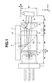
Fig. 1 is a plan view showing a galvano-mirror device
according to a first embodiment of the present invention;
Fig. 2 is a front view showing the galvano-mirror
device in Fig. 1;
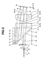
Fig. 3 is a view explaining an example of design data
of the device in the first embodiment;
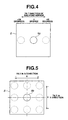
Fig. 4 is a view explaining the movement of a light
spot on the light-receiving surface of a photodetector when
the galvano-mirror tilts in a one-dimensional direction (X-direction
or Y-direction);
Fig. 5 is a view explaining the movement of a light
spot on the light-receiving surface of a photodetector when
the galvano-mirror tilts in two-dimensional directions (X-direction
and Y-direction);
Fig. 6 is a view showing an output state of the
photodetector with respect to the tilt of the galvano-meter;
Fig. 7 is a plan view showing another configuration
example of the galvano-mirror device according to the first
embodiment;
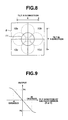
Fig. 8 is a view explaining the movement of a light
spot on the light-receiving surface of the photodetector
when the galvano-mirror tilts in two-dimensional directions
(X-direction and Y-direction) in a galvano-mirror device
according to a second embodiment of the present invention;
Fig. 9 is a view showing an output state of the
photodetector with respect to the tilt of the galvano-meter,
in the configuration in Fig. 8;
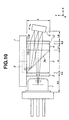
Fig. 10 is a plan view showing a galvano-mirror device
according to a third embodiment of the present invention;
Fig. 11 is a view explaining an example of design data
of the device according to the third embodiment;
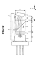
Fig. 12 is a plan view showing another galvano-mirror
device according to the third embodiment;
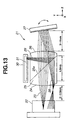
Fig. 13 is a plan view showing the overall
configuration of a tilt sensor according to a fourth
embodiment of the present invention;
Fig. 14 is a view explaining the movement of a light
spot on the light-receiving surface of a photodetector when
the galvano- mirror tilts in a one-dimensional direction (X-direction
or Y-direction);
Fig. 15 is a view showing an output state of the
photodetector with respect to the tilt of the galvano-meter;
Fig. 16 is a view explaining the movement of a light
spot on the light-receiving surface of the photodetector
when the galvano-mirror tilts in two-dimensional directions
(X-direction and Y-direction);
Fig. 17 is a view explaining the movement of a light
spot on the light-receiving surface of the photodetector
when the galvano-mirror tilts in two-dimensional directions
(X-direction and Y-direction), in a galvano-mirror device
according to a fifth embodiment of the present invention;
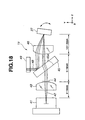
Fig. 18 is a plan view showing a galvano-mirror device
according to a sixth embodiment of the present invention;
Fig. 19 is a front view illustrating the galvano-mirror
device shown in Fig. 17;
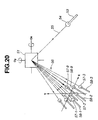
Fig. 20 is a view explaining the configuration of an
optical signal switching system as an application example;
and
Fig. 21 is a view explaining the fundamental
configuration of a magneto-optical disk as an application
example.
BEST MODE FOR CARRYING OUT THE INVENTION
Hereinafter, the embodiments according to the present
invention will be described with reference to the drawings.
First Embodiment
First, detailed reference will be made to a first
embodiment of the present invention referring to the
accompanying drawings.
Figs. 1 to 7 show the first embodiment according to the
present invention. Figs. 1 and 2 are views showing the
overall configuration of a galvano-mirror tilt sensor,
namely, a deflection angle detecting device. This
embodiment is characterized by comprising an optical path
switching means for an optical pickup, tracking detection
means, and a galvano-mirror as optical switching means of
optical fibers.
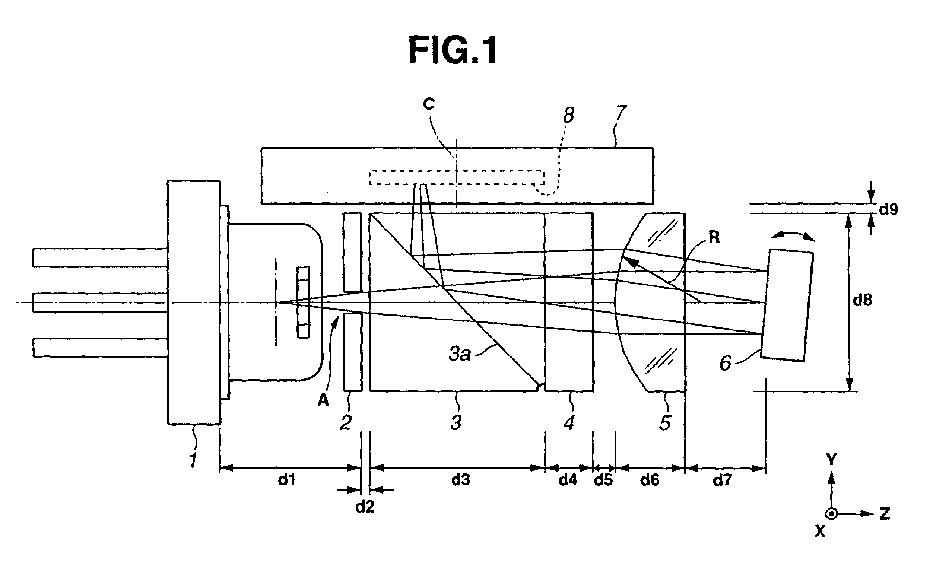
Fig. 1 is a plan view showing a galvano-mirror device
according to the present embodiment, and Fig. 2 is a front
view thereof. Referring to Fig. 1, a laser light A emitted
from a light source module 1 such as a semiconductor laser
is reduced in the beam diameter by an aperture member 2, and
passes through a beam splitter 3, a 1/4 wavelength plate 4,
and a condenser lens 5. Then, the laser light A is applied
to the back surface of a galvano-mirror 6, which is a
movable portion, and is reflected therefrom. The galvano-mirror
6 comprises a movable portion having a mirror, and a
support shaft that supports the mirror. The mirror is
arranged so as to be rotated about the support shaft by a
support-driving port (not shown), and to be tilted in one
direction or two directions.
The beam splitter 3 is a polarizing beam splitter
formed by jointing two prisms, and the joint surface 3a
thereof has thereon a coating having a P-polarization
transmittance of approximately 100% and a S-polarization
reflectance of approximately 100%. The polarized light of
the laser light A is arranged to be P-polarized light with
respect to the joint surface 3a. The polarized light passes
through the beam splitter 3 with a transmittance of
approximately 100%, and is made circularly polarized light
by the 1/4 wavelength plate 4. The laser light A that has
passed through the 1/4 wavelength plate 4, is made to be
substantially parallel light by the condenser lens 5, and is
made incident on the back surface of the galvano-mirror 6.
Here, that the laser light A made incident on the
condenser lens 5 is substantially parallel light, means that
the tilt angle of the mirror is in the range of -5 degrees
to +5 degrees, and preferably, the range of -1 degree to +1
degree.
In the specification and the claims in the present
application, the term "the back surface of the galvano-mirror
or mirror" refers to the back surface of the mirror
body plus the surface of the detecting mirror disposed at a
position predetermined with respect to the above-described
back surface of the mirror body. An example of the
detecting mirror disposed at a position predetermined with
respect to the back surface of the mirror, will be described
later.
The laser light A reflected from the back surface the
galvano- mirror 6 again passes through the condenser lens 5,
and is made incident, as S-polarized light, on the joint
surface 3a of the beam splitter 3 through the 1/4 wavelength
plate 4. The laser light A made incident as a S-polarized
light is arranged so that the optical path thereof is
changed, on the joint surface 3a, so as to bend in the
direction substantially perpendicular to the advancing
optical path (optical path from the light source module 1 to
the joint surface 3a), and is made incident on a
photodetector 7. In other words, in the beam splitter 3,
the laser light A changes the optical path of the reflected
light from the galvano-mirror 6 so as to head toward the
photodetector 7. At this time, the laser light A reflected
from the galvano-mirror 6 is made to become condensed light
by the condenser lens 5, and focuses on the vicinity of the
photodetector 7, thereby forming a light spot with a
diameter of approximately 0.2 mm, on the photodetector 7.
The photodetector 7 is a position sensitive detector
(PSD) for detecting tilt amounts of the galvano-mirror 6
when tilting in X and Y directions, and detects the two-dimensional
positions of a light spot on the photodetector 7.
The tilt amount of the galvano-mirror 6 can be detected
based on the output of the photodetector 7 having a function
of performing angle detection in two-dimensional directions.
The photodetector 7 is a two-dimensional position sensitive
detector (PSD), such as the model S5990 having a light-receiving
surface of 4 mm square and made by Hamamatsu
Photonics Company. In this case, a light spot on the
position sensitive detector (PSD) must be a spot having a
diameter of 0.2 mm or more in order to maintain the
detection accuracy thereof.
In the descriptions hereinafter, in Fig. 1, the
direction in which an light spot produced by the laser light
A reflected from the back surface of the galvano-mirror 6
moves on the photodetector 7, as the result of the rotation
of the galvano-mirror 6 in the direction indicated by the
arrow, is defined as X-direction. On the other hand, in Fig.
2, the direction in which the light spot 9 produced by the
laser light A reflected from the back surface of the
galvano-mirror 6 moves on the photodetector 7 in the
direction indicated by the arrow, is defined as Y-direction.
The specific dimensions of the present embodiment are
as follows: in Fig. 1, d1=3.2 mm, d2=0.2 mm, d3=4 mm,
d4=1.1 mm, d5=0.5 mm, d6=1.6 mm, d7=1.8 mm, d8=4 mm, d9=0.2
mm, and the curvature radius (R) of the convex-side surface
of the condenser lens 5 is 3.05 mm; and in Fig. 2, d10=4 mm.
While, in Fig. 1, all of the outer diameters of the
aperture member 2, beam splitter 3, 1/4 wavelength plate 4,
and condenser lens 5 agree with one another, it is desirable
that the outer diameters of at least one set of two among
them agree with each other. Making the outer diameters
agree with each other allows at least the one set of two to
be inserted along the inner peripheral surface of a common
frame when assembling the device, thereby facilitating the
manufacturing of the device.
Fig. 3 is a view explaining an example of design data
of the device in the first embodiment. Tables 1, 2, and 3
list the design data of the device illustrated in Fig. 3.
Specifically, Table 1 shows a curvature radius, a distance
between surfaces, an eccentricity, a refractive index, and
an Abbe number with respect to each of the surfaces
(represented by r-numbers) of optical components. Table 2
shows data of the eccentricity (1) in Table 1, while Table 3
shows data of the eccentricity (2) in Table 1.
In Table 1, a surface number r1 denotes the surface of a
substance as a light source. A surface number r4 denotes an
aperture surface, which has a diameter of 0.48 cm. Surface
numbers r8 and r12 denote a curved surface of the condenser
lens 5, which has a curvature radius of 3.05. Since
surfaces other than the surface with surface numbers r8 and
r12 are planes, the curvature radii thereof are designated as
infinities. The distance between surfaces is represented by
di (i is a positive integral; the same will apply to Table 1
and Table 4). Here, the di indicates the distance between a
surface r(i+1) and a surface ri. Table 1 shows the distance
data of each di.
The two surfaces represented by surface numbers r10 and
r15 are reflecting surfaces. With respect to the surface r15,
light emitted from the light source passes therethrough
without reflecting therefrom. However, reflected light from
the surface r10 reflects by the surface r15. Therefore, with
regard to the reflecting surface r15 located between a
surface r5 and a surface r6, the data of curvature radius and
data of the distance between surfaces during light
transmission are omitted.
As described above, Table 1 also shows the refractive
indices and Abbe numbers of media between surfaces. The
refractive index of a medium between surfaces is represented
by ni (i is a positive integral; the same will be apply
hereinafter), and the Abbe number is represented by νi. In
Table. 1, ni designates the refractive index of the medium
between a surface r(i+1) and a surface ri, and νi designates
the Abbe number of the medium between a surface r(i+1) and a
surface ri. Since the refractive index of air is 1, the
refractive index when a medium is air, is omitted in Table.
1.
The angle formed between the light beam that is made
incident on the surface r10 and that is on the optical axis
parallel to the Z-axis, namely, an on-axis main light beam D,
and the light beam that is made incident on the surface r10
and that is not parallel to the Z-axis, namely, an off-axis
main light beam E, is +0.0796 degrees or -0.5483 degrees.
Here, when the on-axis main light beam D and the off-axis
main light beam E are parallel to each other, the degree
formed therebetween is 0 degree.
Next, Tables 2 and 3 list the eccentric angle data of
the surfaces r
10 and r
15, respectively.
| | | ECCENTRICITY | (1) |
| X | 0.00 | Y | 0.00 | Z | 0.00 |
| α | -9.10 | β | 0.00 | γ | 0.00 |
| | | ECCENTRICITY | (2) |
| X | 0.00 | Y | 0.00 | Z | 0.00 |
| α | 45.00 | β | 0.00 | γ | 0.00 |
In Tables 2 and 3, α designates the angle by which a
surface rotates about the X-axis along the Y-Z plane, β
designates the angle by which a surface rotates about the Y-axis
along the X-Z plane, and γ designates the angle by
which a surface rotates about the Z-axis along the X-Y plane.
Each of the angle values shown in Tables 2 and 3 is defined
as follows. In Fig. 3, when the sense of rotation is
counterclockwise, the rotational angle takes on a positive
value, and when the sense of rotation is clockwise, the
rotational angle takes on a negative value. Tables 2 and 3
show that the angle α in the eccentricity (1) is -9.10
degrees and that in the eccentricity (2) is 45 degrees,
respectively.
As the beam splitter 3, a glass material such as the
model SFL11 having a high refractive index (n=1.76564) and
made by SCHOTT Corporation, is used. Thereby, the overall
length from the galvano-mirror 6 to the photodetector 7
becomes short, thereby allowing the focal length of the
condenser lens 5 to be short. In addition to an effect of
condensing the laser light A, the condenser lens 5 has an
effect of reducing the moving amount of a light spot on the
photodetector 7 with respect to the tilt of the galvano-mirror
6 by reducing the focal length and decreasing the
angular magnification. This results in the realization of a
wide range tilt sensor that is capable of detection up to a
large tilt amount, or up to a large angle, of the galvano-mirror
6. In this embodiment, the condenser lens 5 is
formed of a general-purpose glass material such as BK7, and
has a focal length of approximately 6 mm. The angular
magnification of the condenser lens 5 with respect to the
back surface of the galvano-mirror 5 is approximately 0.5.
As shown in Figs. 1 and 2, the condenser lens 5 has a
plano-convex shape with respect to the galvano-mirror 6.
Thereby, it is possible to intentionally degrade aberration,
and to enlarge a light spot 9 on the photodetector 7 with
the focal length short.
Figs. 4 to 6 are views specifically explaining the
photodetector 7. Fig. 4 is a view explaining the movement
of a light spot on the light-receiving surface 8 of a
photodetector 7 when the galvano- mirror 6 tilts in a one-dimensional
direction (X-direction or Y direction). Fig. 6
is a view showing an output state of the photodetector 7
with respect to the tilt of the galvano-meter 6. When the
galvano-mirror 6 tilts in a one-dimensional direction (X-direction
or Y direction), the position of a light spot 9a
on the light-receiving surface 8 of the photodetector 7
moves. As shown in Fig. 4, when the galvano-mirror 6 is
located at the neutral position, the central position of the
light spot 9a is located on the center of the light-receiving
surface 8. When the galvano-mirror 6 tilts in
one-dimensional direction, the light spot moves to the
positions as shown by dotted circles in Fig. 4.
At this time, as shown in Fig. 6, the output of the
photodetector 7 substantially linearly change in a certain
range. For example, the output value becomes P2 when the
galvano-mirror 6 tilts by +10 degrees, while the output
value becomes P1 when the galvano-mirror 6 tilts by -10
degrees.
Fig. 5 is a view explaining the movement of a light
spot on the light-receiving surface 8 of a photodetector 7
when the galvano-mirror 6 tilts in two-dimensional
directions (X-direction and Y-direction). When the galvano-mirror
6 tilts in the two-dimensional directions (X-direction
and Y-direction), a light spot 9b on the light-receiving
surface 8 of a photodetector 7 moves in the two-dimensional
directions. As shown in Fig. 5, when the
galvano-mirror 6 is located at the neutral position in the
X-direction and Y-direction, the central position of the
light spot 9b is located on the center of the light-receiving
surface 8. When the galvano-mirror 6 tilts in the
two-dimensional directions, the light spot moves to the
positions as shown by dotted circles in Fig. 5. At this
time, photodetector 7 outputs output values according to the
respective corresponding tilt amounts in the x-direction and
Y-direction.
As shown in Fig. 6, in the galvano-mirror device
according to the present embodiment, the tilt amount, or the
angle, of the galvano-mirror 6 is detectable over a range of
+10 degrees to -10 degrees.
As glass materials for the beam splitter 3, when the
refractive index thereof is in the range of 1.65 to 1.8, the
model S-TIM22 (refractive index n=1.64769) made by OHARA
Corporation, the model SFL11 (n=1.78472) made by SCHOTT
Corporation, the model S-TIH11 (n=1.78472) made by OHARA
Corporation, and the model S-TIH6 (n=1.80518) made by OHARA
Corporation can also be used, beside the above-described
model SFL11 (n=1.76564) made by SCHOTT Corporation.
Next, an example using a detecting mirror will be
described.
As described above, in the present invention, the term
"the back surface of the galvano-mirror" refers to the back
surface of the mirror body plus the surface of the detecting
mirror disposed at a position predetermined with respect to
the above-described back surface of the mirror body. Fig. 7
is a view showing the configuration of a mirror deflection
angle detecting device having the detecting mirror disposed
at a position predetermined with respect to the back surface
of the mirror body.
In Fig. 7, the deflection angle detecting device
comprises a light deflector 14 having a mirror 6, a flexible
printed circuit board (FPC) 15, a housing 13, a
semiconductor laser 1, a polarizing beam splitter (PBS) 3, a
1/4 wavelength plate 4, a condenser lens 5, and a position
sensitive detector (PSD) 7.
The semiconductor laser 1 is installed at an opening
portion 13b of a housing 13. One surface of the PBS 3 is
adhered to the pedestal of the housing 13. The condenser
lens 5 is affixed to an opening portion formed at the
installation surface of the light deflector 14. The PSD 7
is adhered to the housing 13.
The light deflector 14 includes a coil holder 16a,
which is a movable portion, and a magnet holder 16b, which
is a fixed portion. The coil holder 16a and the magnet
holder 16b are molded of a nonconductive plastic, such as
liquid crystal polymer containing titanate whiskers. Four
springs 16c as support members hold the coil holder 16a and
the magnet holder 16b at both ends thereof. The coil holder
16a, which is a movable portion, includes a mirror 6, a
first coil 16d, and a second coil 16e. The first and second
coils 16d and 16e are supplied with a power from the FPC 15.
Three terminals of the semiconductor laser 1 is soldered to
the soldering portion 15b of the FPC 15.
A magnet 17a for the first coil 16d and a magnet (not
shown) for the second coil 16e are affixed to the magnet
holder 16b. A yoke 17b is adhered to the magnets.
The mirror 6 is affixed to an installation portion (not
shown) at the surface-side central portion of the coil
holder 16a by positioning the outer periphery portion
thereof and securely adhering it. The reflecting surface 6a
of mirror 6 on the surface side is covered with a coating
having a high refractive index. Also, a mirror 18 is
affixed to an installation portion (not shown) at the back
surface-side central portion of the coil holder 16a by
positioning the outer periphery portion thereof and securely
adhering it. The mirror 18 as a detecting mirror is
disposed at a predetermined position with respect to the
mirror 6. In the space between the mirror 6 and the mirror
18, the central portion of an arm 19 as a support member is
located. The two mirrors 6 and 18, therefore, are held in
the movable portion so as to oppose to each other. The
movable portion is supported at a pivot 16f so as to be
tiltable with respect to the fixed portion.
Light from the semiconductor laser 1 is made incident
on the PBS 3 as P-polarized light, passes through the
polarization surface 3a thereof, and is made incident on the
back surface (reflecting surface) 18a of the mirror 18 as
detecting mirror, via the 1/4 wavelength plate 4 and the
condenser lens 5. The light reflected from the mirror 18 is
made incident on the PBS 3 through the condenser lens 5 and
the 1/4 wavelength plate 4. Since this light that is made
incident on the PBS 3 after being reflected from the mirror
18 passes through the 1/4 wavelength plate 4 twice in total
by the round trip, the polarization surface rotates by 90
degrees and becomes S-polarized light. As a result, the S-polarized
light is reflected by the polarization surface 3a
of the PBS 3 and is made incident on the light-receiving
surface 8 of the PSD 7. The PSD 7 outputs, as current
values, the positions in two directions of the light applied
to the light-receiving surface 8.
On the light-receiving surface 8, a light spot is
formed at a position corresponding to the tilt of the mirror
18, and hence, that of the mirror 6, thereby allowing a tilt,
that is, a deflection angle, of the mirror 6, to be detected.
The mirror deflection angle detecting device having a
detecting mirror disposed at a position predetermined with
respect to the back surface of the mirror body, as described
with reference to Fig. 7, can be applied to any one of
second to seventh embodiments, which will be described below.
In the second to seventh embodiments, therefore,
descriptions of the mirror deflection angle detecting device
shown in Fig. 7 are omitted.
An example of a two-dimensional galvano-mirror
utilizing an electrostatically driven motor that can be
biaxially rotatable, is disclosed in Japanese Unexamined
Patent Application Publication No. 5-60993. In the galvano-mirror
set forth in this Japanese Unexamined Patent
Application Publication No. 5-60993, as shown in Fig. 3
therein, a reflecting plate 28 and an inner frame 25, which
are provided so that the centroid positions of two rotating
shafts agree with each other, are supported by flexible
beams 26 and 27 and flexible beams 23 and 24, respectively.
When a voltage is applied to one of fixed electrodes 31 and
32 or one of fixed electrodes 33 and 34 that are provided
under the reflecting plate 28 and inner frame 25, the
reflecting plate 28 and inner frame 25 are rotated about the
flexible beams 23, 24, 26, and 27 under electrostatic forces.
Accordingly, such a galvano-mirror may also be used as a
mirror in the present embodiment. Likewise, in any one of
the second to seventh embodiments described below, such a
galvano-mirror as set forth in this Japanese Unexamined
Patent Application Publication No. 5-60993 may be employed
as a mirror.
Therefore, the galvano-mirror device according to the
present embodiment can be applied to any equipment that
requires detection with respect to a wide range of tilt
amounts of the galvano-mirror, such as optical path
switching device for an optical pickup, a tracking detection
device for an optical disk device, and an optical switching
means of optical fibers. In the galvano-mirror device
according to the present embodiment, since reflected light
is bent in a direction perpendicular to the direction of the
optical path of light emitted from the light source and is
introduced into the photodetector, as well as a condenser
lens is employed, the overall size of the galvano-mirror
device becomes compact. Similarly, in an application device
such as a tracking device for an optical disk device, a
compact layout is possible, thereby allowing the overall
size of the device to be compact.
Second Embodiment
Next, a second embodiment according to the present
invention will be described with reference to the
accompanying drawings.
Fig. 8 is a view explaining the movement of a light
spot on the light-receiving surface 8 of the photodetector 7
when the galvano-mirror 6 tilts in two-dimensional
directions (X-direction and Y-direction) in a photodetector
7 as tilt sensor according to the second embodiment. Fig. 9
is a view showing an output state of the photodetector with
respect to the tilt of the galvano-meter, in the
configuration in Fig. 8.
The present embodiment is characterized by comprising a
quadripartite photodetector (PD) instead of a position
sensitive detector (PSD), as a tilt sensor photodetector.
The overall configuration of the galvano-mirror in this
embodiment is the same as that of the first embodiment shown
in Figs. 1 and 2, and only the photodetector is different
from that of the first embodiment. The description of the
present embodiment, therefore, will be made of only the
portions different from those of the first embodiment.
In this embodiment, the focal length of the condenser
lens 5 is approximately 9 mm, and the diameter of a light
spot of the laser light A condensed on the photodetector 7
that has a function of detecting two-dimensional angles is
as large as 1.0 to 1.5 mm. The light-receiving surface 10
of the photodetector 7 is divided into four light-receiving
surfaces. The respective four divided light-receiving
surfaces are designated as 10a, 10b, 10c, and 10d.
In Fig. 8, when the galvano-mirror tilts in the two-dimensional
directions (X-direction and Y-direction), a
light spot 11 on the light-receiving surface 10a moves in
the two-dimensional directions. Here, when the outputs of
the photodetector at the light-receiving surfaces 10a, 10b,
10c, and 10d, respectively, are designated as 12a, 12b, 12c,
and 12d, the outputs in the X-direction and Y-direction are
determined by the following expressions.
the output in the X-direction:
(12a + 12c - 12b - 12d)/(12a + 12b + 12c + 12d)
the output in the Y-direction:
(12a + 12b - 12c - 12d)/(12a + 12b + 12c + 12d)
Thus, the obtained output in each of the X-direction and Y-direction
substantially linearly changes according to the
tilt amount of the galvano-mirror 6, as in the case of the
first embodiment.
In the configuration in this embodiment, the size of
the light-receiving surface is 4 mm square, and as shown in
Fig. 9, the detection range with respect to the tilt of the
galvano-mirror 6 is approximately between the range +5 to +6
degrees and the range -5 to -6 degrees, in each of the X-direction
and Y-direction. For example, the output value
becomes P4 when the galvano-mirror 6 tilts by -6 degrees,
while the output value becomes P3 when the galvano-mirror 6
tilts by +6 degrees.
Therefore, according to the configuration of the second
embodiment, as in the case of the first embodiment, a
galvano-mirror device having a wide detection range and a
compact size, can be implemented. Similarly, in an
application device, a compact layout can be achieved,
thereby allowing the overall size of device to be compact.
Third Embodiment
A third embodiment according to the present invention
will be now described with reference to the drawings. Figs.
10 and 11 are views explaining a tilt sensor according to
the present embodiment. Fig. 12 is a plan view showing
another example of the galvano-mirror device according to
the third embodiment. In these drawings, the same
components as those in the first embodiment are designated
by the same reference numerals, and explanations thereof are
omitted. Descriptions are only made of portions that are
different from those of the first embodiment.
Fig. 10 is a plan view showing the galvano-mirror
device according to the present embodiment. Instead of
using a plano-convex lens as a condenser lens for the tilt
sensor, this embodiment is characterized by using a Fresnel
lens having a zone plate, or a lens having a diffractive
optical element (DOE) or a hologram.
In Fig. 10, reference numeral 12 denotes a Fresnel lens.
In this embodiment, as a condenser lens, a Fresnel lens 12
with a thickness of approximately 0.5 mm is employed. The
Fresnel lens 12 is joined to a 1/4 wavelength plate 4, and
the beam splitter 3, the 1/4 wavelength plate 4, and the
Fresnel lens 12 are integrally joined.
Fig. 10 shows the specific dimensions of the present
embodiment. That is, d1=3.2 mm, d2=0.2 mm, d3=4 mm, d4=1.1
mm, and d8=4 mm; and the distance from the surface 12a of
the Fresnel lens 12 to the surface of the galvano-mirror 6
is 1.8 mm.
Since the thickness of the Fresnel lens 12 and the
distance between the 1/4 wavelength plate 4 and the Fresnel
lens 12 become small as compared with the configuration of
the first embodiment, the distance from the sensor light
source 1 to the galvano-mirror 6 can be reduced by 1.6 mm,
over the case of the first embodiment. This allows a
compact configuration to be realized.
Simultaneously, since the distance from the Fresnel
lens 12 to the photodetector 7 is also reduced, the focal
length of the Fresnel lens 12 is as short as approximately 5
mm while that of the condenser lens 5 in the first
embodiment is approximately 6 mm. For the Fresnel lens 12,
a plastic glass material such as ZEONEX™ or an acrylic resin
is used, and a zone plate is formed on the surface 12a of
the Fresnel lens 12, using a glass material such as quartz.
Here, the "zone plate" refers to one that is formed by
concentrically arranging a plurality of ring bands so that
the light from all ring bands converges to a point in phase.
Herein, the same refractive index as that of the lens is
obtained by utilizing a deflection phenomenon due to a
minute structure wherein transparent portions and absorptive
portions are alternately formed.
By reducing the focal length of the Fresnel lens 12,
the angular magnification can be reduced, and thereby the
moving amount of a spot on the photodetector 7 with respect
to the tilt of the galvano-mirror 6 becomes smaller. In
this embodiment, the tilt amount of the galvano-mirror 6 is
detectable in the range of -12 degrees to +12 degrees.
Thereby, a tilt sensor having a wider detection range is
implemented using the same photodetector.
Also, integrally joining the beam splitter 3, the 1/4
wavelength plate 4, and the Fresnel lens 12, eliminates the
need for a fixing portion for the Fresnel lens 12. As a
result, even the photodetector 7 can be integrally joined to
the beam splitter 3 securely by pressing the photodetector 7
against the beam splitter 3, thereby facilitating the
assembly and adjustment of the device.
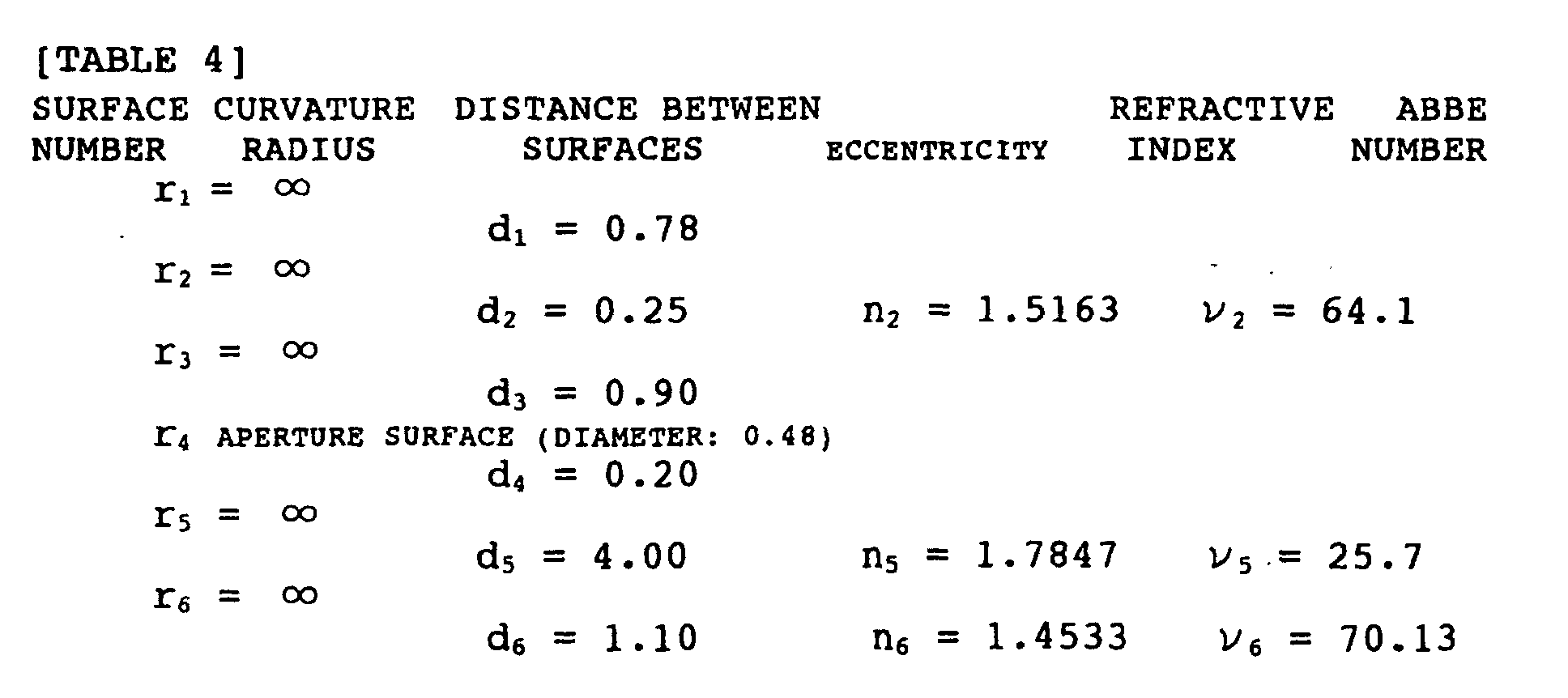
Fig. 11 is a view explaining an example of design data
of the device according to this embodiment.
Lists 4, 5, and
6 show design data of the device in Fig. 11. Specifically,
Table 4 shows a curvature radius, a distance between
surfaces, an eccentricity, a refractive index, and an Abbe
number with respect to each of the surfaces (represented by
r-numbers) of optical components. Table 5 shows data of the
eccentricity (1) in Table 4, while Table 6 shows data of the
eccentricity (2) in Table 4. Here, the curvature radius R
showing the surface shape of each of the hologram surfaces
[1] in Table 4 is expressed by the following expression (1).
In Table 4, a surface number r1 denotes the surface of a
substance as a light source. A surface number r4 denotes an
aperture surface, which has a diameter of 0.48 cm. Surface
numbers r8 and r10 denote a hologram surface [1]. Since
surfaces other than the surface with surface numbers r8 and
r10 are planes, the curvature radii thereof are designated as
infinities. The distance between surfaces is represented by
di. Here, the di indicates the distance between a surface
r(i+1) and a surface ri. Table 4 shows distance data of each
di.
The two surfaces represented by surface numbers r9 and
r13 are reflecting surfaces. With respect to the surface r13,
the light emitted from the light source pass therethrough
without reflecting therefrom. However, the reflected light
from the surface r9 reflects from the surface r13. Therefore,
with regard to the reflecting surface r13 located between a
surface r5 and a surface r6, the data of curvature radius and
data of the distance between surfaces during light
transmission are omitted.
Table 4 also shows the refractive indices and Abbe
numbers of media between surfaces. The refractive index of
a medium between surfaces is represented by ni, and the Abbe
number is represented by νi. In Table. 4, ni designates the
refractive index of the medium between the surface r(i+1) and
the surface ri, and νi designates the Abbe number of the
medium between a surface r(i+1) and a surface ri. Since the
refractive index of air is 1, the refractive index when a
medium is air, is omitted in Table. 1.
The angle formed between the light beam that is made
incident on the surface r9 and that is on the optical axis
parallel to the Z-axis, namely, an on-axis main light beam D,
and the light beam that is made incident on the surface r9
and that is not parallel to the Z-axis, namely, an off-axis
main light beam E, is +0.0796 degrees or -0.5483 degrees.
Here, when the on-axis main light beam D and the off-axis
main light beam E are parallel to each other, the degree
formed therebetween is 0 degree.
Next, Tables 5 and 6 list the eccentric angle data of
the surfaces r
9 and r
13, respectively.
| ECCENTRICITY (1) |
| X | 0.00 | Y | 0.00 | Z | 0.00 |
| α | -10.00 | β | 0.00 | γ | 0.00 |
| ECCENTRICITY (2) |
| X | 0.00 | Y | 0.00 | Z | 0.00 |
| α | 45.00 | β | 0.00 | γ | 0.00 |
In Tables 5 and 6, α designates the angle by which a
surface rotate about the X-axis along the Y-Z plane, β
designates the angle by which a surface rotate about the Y-axis
along the X-Z plane, and γ designates the angle by
which a surface rotate about the Z-axis along the X-Y plane.
Each of the angle values shown in Tables 5 and 6 are defined
as follows. In Fig. 11, when the sense of rotation is
counterclockwise, the rotational angle takes on a positive
value, and when the sense of rotation is clockwise, the
rotational angle takes on a negative value. Tables 5 and 6
show that the angle α in the eccentricity (1) is -10.00
degrees and that in the eccentricity (2) is 45 degrees,
respectively.
[Mathematical Expression 1]
R = C1X + C1Y
where C1 = -9.9 × 10⁻²
Fig. 12 is a plan view showing an example of another
layout of galvano-mirror device according to the present
embodiment, which is made more compact in size.
Fig. 12 shows the specific dimensions of the present
embodiment. That is, d1=3.2 mm, d2=0.2 mm, d3=4 mm, d4=0.4
mm, and d8=3 mm; the thickness of the Fresnel lens 12 is 0.5
mm, and the distance from the surface 12a of the Fresnel
lens 12 to the surface of the galvano-mirror 6 is 1.0 mm.
As shown in Fig. 12, as the 1/4 wavelength plate 4, a
thin type with a thickness of 0.4 mm is used, and the beam
splitter 3 is not 4 mm square, but 3 mm square. The
distance between the Fresnel lens 12 and the galvano-mirror
6 is reduced to approximately 1 mm. Thereby, the distance
from the sensor light source 1 to the galvano-mirror 6 can
be shorten by 1,5 mm, and also the length of the device in
the X-direction can be shortened by approximately 1.5 mm,
over the case shown in Fig. 10.
In this embodiment, the focal length of the Fresnel
lens 12 is approximately 4 mm, and the tilt amount of the
galvano-mirror 6 is detectable in the range of -10 degrees
to +10 degrees. The sensor light source 1 is of a package
type with a diameter of 5.6 mm in Fig. 12. It is possible,
however, to realize a more compact layout by using a package
with a diameter of 3.3 mm. The dimensions of the light-receiving
surface can also be reduced to 3 mm square.
Instead of using the Fresnel lens 12, a diffractive
optical element (DOE) lens having a DOE, or a hologram lens
having a hologram may be used. In this case, a deflection
grating or a hologram is respectively provided instead of a
zone plate, resulting in the same configuration example as
those in Figs. 10 and 12. Thus, a similar effect to the
device example with a configuration using a Fresnel lens is
obtained.
The condenser lens in this embodiment can have a focal
length approximately in the range of 1.5 to 7 mm.
With these arrangements, as in the case of the first
embodiment, a galvano-mirror device that has a wide
detecting range with respect to the tilt of the galvano-mirror
and that is compact in size, can be achieved.
Fourth Embodiment
Figs. 13 to 16 are views showing a fourth embodiment
according to the present invention. Fig. 13 is a plan view
showing the overall configuration of a tilt sensor according
to the present embodiment. Fig. 14 is a view explaining the
movement of a light spot on the light-receiving surface of
the photodetector when the galvano-mirror tilts in a one-dimensional
direction (X-direction or Y direction). Fig. 15
is a view showing an output state of the photodetector with
respect to the tilt of the galvano-meter. Fig. 16 is a view
explaining the movement of a light spot on the light-receiving
surface of the photodetector when the galvano-mirror
tilts in two-dimensional directions (X-direction and
Y-direction).
In a tilt sensor device 21 in this embodiment shown in
Fig. 13, laser light 23 emitted from a sensor light source
22 is made substantially parallel light by a first condenser
lens 24, and passes through a prism 25.
Here, the prism 25 is a beam splitter that is formed by
using, as a glass material, a general-purpose glass material
such as the model S-BSL7 made by OHARA Company, and the
surface 25a of the prism 25 is covered with a coating having
a transmittance of approximately 50% and a refractive index
of approximately 50%.
The laser light 23 passes trough the prism 25 with a
transmittance of approximately 50%, and after being slightly
condensed through second condenser lens 26, the laser light
23 is reflected from the back surface of a galvano-mirror 27.
The reflected laser light 23 again passes through the second
condenser lens 26, and is separated at the surface 25a of
the prism 25 into transmitted light 28 and reflected light
29.
The reflected light 29 is arranged so that the optical
path thereof is changed, on the surface 25a, so as to bend
in the direction substantially perpendicular to the
advancing optical path, and is made incident on a
photodetector 30. At this time, the reflected light 29 is
made condensed light by the second condenser lens 26, and
forms a spot with a diameter of approximately 0.2 to 0.5 mm
on the photodetector 30.
In this embodiment, the two condenser lenses 24 and 26
are formed of the same glass material as that of the prism
25, and are joined to both surfaces of the prism 25. If
there is a space more than adequate, a separated type
configuration may also be adopted. The two condenser lenses
24 and 26 have substantially the same focal length, which is
approximately 6 to 8 mm. Here, the prism as a beam splitter
and the two condenser lenses may be integrally formed, or
molded, into one piece member.
In case where only one condenser lens is provided, the
lens aperture would have to be reduced in order to narrow
the beam diameter of the laser light 23, thereby causing a
light amount deficiency. Also, in case where some distances
among portions due to the restriction on mechanical
construction, the focal length of condenser lens would
become long, so that the movement of a light spot on the
photodetector 30 would become large, thereby inhibiting a
wide range detection with respect to the tilt of the
galvano-mirror 27.
Accordingly, by using the two condenser lenses 24 and
26, the tilt sensor device 21 according to the present
embodiment can reduce the light amount deficiency of the
laser light 23, thereby making effective use of the laser
light. Also, even when there is a restriction on mechanical
construction, it is possible to optimize the diameter of a
spot and the moving amount thereof on the photodetector 30,
by changing the focal length of the two condenser lenses 24
and 26. These allow a wide range detection with respect to
the tilt of the galvano-mirror 27.
The photodetector 30 is a position sensitive detector
(PSD) for detecting the tilt amount of the galvano-mirror 27
when tilting in X and Y directions, and detects the tilt
amounts thereof by detecting the two-dimensional positions
of a light spot on the photodetector 30.
In this embodiment, the photodetector 30 is a PSD, such
as the model S5990 having a light-receiving surface of 4 mm
square and made by Hamamatsu Photonics Company. However,
any photodetector having the similar size to that of the
model S5990 may be used without problems.
Figs. 14 and 15 are views explaining the details of the
photodetector 30. Fig. 14 shows the movement of a light
spot when the galvano-mirror 27 tilts in a one-dimensional
direction (X-direction or Y direction). When the galvano-mirror
27 tilts in a one-dimensional direction, the position
of a spot 32a on the light-receiving surface 31 of the
photodetector 30 moves. At this time, the output of the
photodetector 30 substantially linearly changes in a
definite range, as shown in Fig. 15.
Fig. 16 shows the movement of a light spot when the
galvano- mirror 27 tilts in two-dimensional directions.
When the galvano-mirror 27 tilts in the X- and Y-directions,
the position of a spot 32b on the light-receiving surface 31
of the photodetector 30 moves in the two-dimensional
directions. At this time, the output in each of the
directions becomes similar to that shown in Fig. 15.
According to the arrangement of the present embodiment,
the detection range with respect to the tilt amount, that is,
the tilt angle, of the galvano-mirror 27 is between the
range -7 to -10 degrees and the range +7 to +10 degrees.
This embodiment, therefore, can be used for an optical path
switching means for an optical pickup, tracking detection
means, and an optical switching means of optical fibers,
which require a wide range detection with respect to the
tilt of the galvano-mirror.
By using the two condenser lenses 24 and 26, the light
amount deficiency of the laser light 23 can be reduced, and
thereby the laser light can be effectively utilized. Even
when there is a restriction on mechanical construction, it
is possible to optimize the diameter of a spot and the
moving amount thereof on the photodetector 30, by changing
the focal length of the two condenser lenses 24 and 26.
These allow a wide range detection with respect to the tilt
of the galvano-mirror 27.
Moreover, since the reflected light 29 is introduced
into the photodetector 30 while being bent, the tilt sensor
31 can be configured by a compact mechanical layout.
Fifth Embodiment
The details of a photodetector for a tilt sensor device
according to a fifth embodiment of the present invention
will be described with reference to Fig. 17. Fig. 17 is a
view explaining the movement of a light spot on the light-receiving
surface of the photodetector when the galvano-mirror
tilts in two-dimensional directions (X-direction and
Y-direction), in a galvano-mirror device according to the
fifth embodiment.
Since the fifth embodiment is substantially the same as
the fourth embodiment, only the portions different from
those of the fourth embodiment will be described. The
configuration of the tilt sensor according to the present
embodiment is the same as that shown in Fig. 13.
This embodiment is characterized by comprising, as the
photodetector 30 for the tilt sensor, a quadripartite
photodetector (PD) having quadripartite light-receiving
surfaces corresponding to quadripartite photodiodes adopted
as a photodetector, instead of a position sensitive detector
(PSD).
In this embodiment, the focal length of a second
condenser lens 26 is approximately 10 to 12 mm, and the
diameter of a light spot of the laser light A condensed on
the photodetector 30 is as large as 1.0 to 1.5 mm. As shown
in Fig. 17, the light-receiving surface 31 of the
photodetector 30 is divided into four light-receiving
surfaces 31a to 31d.
When the galvano-mirror 27 tilts in the two-dimensional
directions (X-direction and Y-direction), a light spot 32 on
the light-receiving surface 31 moves in the two-dimensional
directions. Here, when the outputs of the light-receiving
surfaces 31a to 31d, respectively, is designated as A to D,
the outputs in the X-direction and Y-direction are
determined by the following expressions.
the output in the X-direction:
(A + C - B - D)/(A + B + C + D)
the output in the Y-direction:
(A + B - C - D)/(A + B + C + D)
Thus, the obtained output in each of the X-direction and Y-direction
substantially linearly changes, as in the case of
the fourth embodiment.
In the arrangement of this embodiment, the size of the
light-receiving surface 31 is 4 mm square, and the detection
range with respect to the tilt of the galvano-mirror 27 is
approximately between the range -5 to -6 degrees and the
range +5 to +6 degrees.
Therefore, as in the case of the fourth embodiment,
this arrangement can be used for a wide range detection with
respect to the tilt of galvano-mirror by a compact
mechanical layout.
Sixth Embodiment
Figs. 18 and 19 are views showing a sixth embodiment
according to the present invention. Fig. 18 is a plan view
showing a galvano-mirror device according to the sixth
embodiment, and Fig. 19 is a front view thereof.
Since the sixth embodiment is substantially the same as
the fourth embodiment, descriptions are only made of
portions thereof that are different from those of the fourth
embodiment. The same components as those in the fourth
embodiment are designated by the same reference numerals,
and explanations thereof are omitted.
This embodiment is characterized by using a flat plate
instead of a prism, as a beam splitter to change the optical
path.
In the tilt sensor 1a of the present embodiment shown
in Figs. 18 and 19, the laser light 42 emitted from the
sensor light source 41 is made substantially parallel light
by a first condenser lens 43, the beam diameter thereof is
reduced by the aperture 44, and the laser light is made
incident on a flat plate 45.
Here, the flat plate 45 is a beam splitter that is
formed by using, glass material, a glass such as the model
S-BSL7 made by OHARA Company and white board, and a plastic
such as ZEONEX™. The surface 45a of the flat plate 45 is
covered with a coating having a transmittance of
approximately 50% and a refractive index of approximately
50%.
The laser light 42 passes trough the flat plate 45 with
a transmittance of approximately 50%, and is condensed on
the vicinity of the back surface of the galvano-mirror 27,
by a second condenser lens 46. At this time, a condensing
point is located approximately 0.3 to 0.5 mm before the
galvano-mirror 27, in order to prevent a light amount
deficiency caused by dusts on the surface of the galvano-mirror
27.
The laser light 42 reflected from the back surface of
the galvano-mirror 27, again passes through the second
condenser lens 46, and after being made substantially
parallel light, the laser light 42 is reflected from the
surface 45a of the flat plate 45, as reflected light 48
separated from the substantially parallel light.
The reflected light 48 is arranged so that the optical
path thereof is changed, on the surface 45a, so as to bend
in the direction substantially perpendicular to the
advancing optical path, and is made incident on a
photodetector 49, thereby forming a spot with a diameter of
approximately 0.2 mm on the photodetector 49.
The two condenser lens 43 and 46 are the same type of
aspherical lens having a focal length of approximately 2 mm,
and wavefront aberrations thereof are in the range of 0.01
to 0.05 λrms in RMS values. Here, the RMS value of the
wavefront aberration is the root mean square value of a P-V
value, which is a peak-to-valley value, of a wavefront
aberration. The unit of wavefront aberration is λ, which is
a wavelength of light.
As in the case of the fourth embodiment, the
photodetector 49 is a PSD, such as the model S7848 having a
light-receiving surface of 2 mm square and made by Hamamatsu
Photonics Company. However, any photodetector having the
similar size to that of the model S7848 may be used without
problems.
Using the two condenser lenses 43 and 46 allows the
laser light 42 to become substantially parallel light and to
be reduced in the beam diameter without causing a light
amount deficiency, and enables the laser light 42 to be
detected with respect to wide range tilt of the galvano-mirror
27, without causing vignetting outside effective
ranges on portions. Also, making the laser light
substantially parallel light allows the limitation to the
distance between portions to be reduced.
With these arrangements, as in the case of the fourth
embodiment, tilt amounts of the galvano-mirror 7 can be
detected, and also, by using the flat plate 45, a more
inexpensive and compact mechanical layout can be implemented.
Seventh Embodiment
A seventh embodiment according to the present invention
is characterized by comprising, as first and second
condenser lens, Fresnel lenses, DOE lenses having a
deflecting optical element or a diffraction grating, or
hologram lenses, instead of ordinary spherical lenses.
Since the configuration of the seventh embodiment
according to the present invention is substantially the same
as those of the fourth to sixth embodiments, descriptions
are only made of portions thereof that are different from
those of the fourth to sixth embodiments. The configuration
of the tilt sensor according to this embodiment is the same
as those shown in Figs. 13 to 19.
With respect to both or one of the first and second
lenses of each of the fourth to sixth embodiments, Fresnel
lenses, DOE lenses, or hologram lenses that have the same
focal length as that of the first and second condenser
lenses of the fourth to sixth embodiments, are used.
Thereby, similar effects to those of ordinary lenses can be
achieved.
Since the above-described lens can provide a thin
optical component having a thickness of below 1 mm, over the
condenser lenses in the first to second embodiments, the
above-described lens enables the device to become more
compact configuration. Furthermore, in the case of a
hologram lens, by directly applying a hologram on each of
the surfaces of the bean splitter, it is possible to unify
the beam splitter and the first and second condenser lenses
into one component. This allows the number of components to
be reduced, and enables a galvano-mirror deflection angle
detecting device having a layout that is even more compact
and inexpensive to be achieved.
Application Examples
The galvano-mirror device equipped with the mirror
deflection angle detecting device according to the above-described
embodiments can be applied to an optical signal
switching system, which performs the switching of an optical
path, an optical disk, and the like. Some of these
application examples will be described below.
First, reference is made to an application example with
respect to an optical signal switching system, of the mirror
deflection angle detecting device according to the above-described
embodiments. Fig. 20 is a view explaining the
configuration of an optical signal switching system. In Fig.
20, a mirror 51 as a light deflecting element is selectively
driven about a rotating shaft Ox parallel to the X-axis and
a rotating axis oy parallel to the Y-axis perpendicular to
the X-axis.
An optical signal is transmitted through the inside of
an optical fiber 53 as an input cable. The incident light
55 for optical communication that is emitted as parallel
light from one optical fiber 53 through a lens 54, is
reflected by a mirror 51. The reflected light 56 is
selectively made incident on one of nine lenses in total 57-1
to 57-9, which are arranged on three-stage planes
substantially perpendicular to the reflected light 56, and
is arranged to be made condensedly incident on either one of
respective corresponding nine optical fibers 58-1 to 58-9.
The optical signal is received by either one of the
optical fibers 58-1 to 58-9 as output cables, and is
transmitted through the inside of the fiber. Although a
single input fiber is used here, a plurality of fibers may
be used to constitute an input fiber unit, as in the case of
the plurality of output fibers.
The reflected light 56 from the mirror 51 is deflected
in the X-direction, (i.e., the horizontal direction in Fig.
20) by tilting the mirror 51 about the rotating shaft Oy,
while the reflected light 56 from the mirror 51 is deflected
in the Y-direction, (i.e., the vertical direction in Fig.
20) by tilting the mirror 51 about the rotating shaft Ox.
Thereby, the optical path of the optical signal from the
input fiber is selectively changed, and the reflected light
56 is made incident on either one of the nine lenses 57-1 to
57-9. The light that has made incident on the lens 57 is
made incident on either one of the respective corresponding
optical fibers 58-1 to 58-9. In this manner, the optical
fiber that outputs light from one optical fiber 53 on the
input side, can be selected out of the nine optical fibers
58-1 to 58-9.
More specifically, when the place of the input fiber
from which an inputted optical signal is to be emitted is
specified out of the plurality of input fibers, and the
place of the output fiber to transmit the optical signal is
specified out of the plurality of output fibers, a position
detecting light is applied to the back surface of at least
one mirror 51 disposed in the optical path between the input
fiber and the out put fiber. At this time, by receiving, by
a photodetector, the position detecting light reflected from
the back surface of the mirror 51, the deflection amount of
the tilt angle of the mirror is detected, and the tilt angle
of the mirror 51 is adjusted.
Therefore, by equipping the mirror 51 in a galvano-mirror
device as a light switching device with the above-described
mirror deflection angle detecting device, an
optical signal switching system can be implemented.
Next, reference is made to an application example with
respect to an optical disk, of the mirror deflection angle
detecting device according to the above-described
embodiments.
Fig. 21 is a view explaining the fundamental
configuration of a magneto-optical disk. Referring to Fig.
21, in a magneto-optical disk driving device 61, an optical
disk 62 is mounted on the rotating shaft of a spindle motor
(not shown). In order to reproduce or record information in
the optical disk, a pivoting arm (coarse motion arm) 63 is
affixed so as to become parallel to recording surface of the
optical disk 62. The pivoting arm 63 is arranged so as to
be pivoted about a pivot 65 by a voice coil motor 4. A
floating optical head 66 equipped with an optical element is
mounted at the front end of the pivoting arm 63 opposite to
the optical disk 62. In the vicinity of the pivot 65 of the
pivoting arm 63, there is provided a light source module 67
including a light source unit and a light-receiving unit,
and is actuated in conjunction with the pivoting arm 63.
The floating optical head 66 comprises a floating
slider, an objective lens, a solid immersion lens, and a
magnetic coil. A riser mirror 68 for introducing a laser
flux into the floating optical head 66 is adhered to the
front end of the pivoting arm 63. Also, a deflection mirror
69 is provided on the pivoting arm 63. The parallel laser
flux emitted from the light source module 67 is converged on
the optical disk 62 by the floating optical head 66. In
addition, a Galvano-motor (not shown) is affixed to the
deflection mirror 69, and is arranged so as to change the
travelling direction of the laser flux by a minute angle.
Therefore, the present invention can be applied to a
optical disk device by providing the above-described mirror
deflection angle detecting device corresponding to the
mirror 69.
The mirrors shown in the above-described plurality of
embodiments and the application examples thereof has been
explained as galvano-mirrors wherein a mirror is generally
equipped with a driving coil. However, a mirror to which
the present invention can be applied, is not limited to such
a type of galvano-mirror. The present invention can also be
applied to a mirror such that an electrostatic motor is used
or that a permanent magnet is adhered to the mirror with a
driving coil provided on a fixed portion.
While embodiments of the present invention have been
described, it should be understood that the present
invention is not limited to those embodiments and that
various changes and modifications thereof can be made
without departing from the spirit and scope of the present
invention.
INDUSTRIAL APPLICABILITY
As described above, according to the present invention,
there are provided a mirror angle detecting device having a
wide detection range with respect to the tilt amount of
mirror and capable of being formed into a compact size, an
optical signal switching system, and an optical signal
switching method.