EP1484481A1 - Exhaust emission control device and casing structure of the control device - Google Patents
Exhaust emission control device and casing structure of the control device Download PDFInfo
- Publication number
- EP1484481A1 EP1484481A1 EP02700675A EP02700675A EP1484481A1 EP 1484481 A1 EP1484481 A1 EP 1484481A1 EP 02700675 A EP02700675 A EP 02700675A EP 02700675 A EP02700675 A EP 02700675A EP 1484481 A1 EP1484481 A1 EP 1484481A1
- Authority
- EP
- European Patent Office
- Prior art keywords
- filter
- exhaust gas
- inner case
- case
- purifying device
- Prior art date
- Legal status (The legal status is an assumption and is not a legal conclusion. Google has not performed a legal analysis and makes no representation as to the accuracy of the status listed.)
- Withdrawn
Links
Images





Classifications
-
- F—MECHANICAL ENGINEERING; LIGHTING; HEATING; WEAPONS; BLASTING
- F01—MACHINES OR ENGINES IN GENERAL; ENGINE PLANTS IN GENERAL; STEAM ENGINES
- F01N—GAS-FLOW SILENCERS OR EXHAUST APPARATUS FOR MACHINES OR ENGINES IN GENERAL; GAS-FLOW SILENCERS OR EXHAUST APPARATUS FOR INTERNAL-COMBUSTION ENGINES
- F01N13/00—Exhaust or silencing apparatus characterised by constructional features
- F01N13/14—Exhaust or silencing apparatus characterised by constructional features having thermal insulation
-
- F—MECHANICAL ENGINEERING; LIGHTING; HEATING; WEAPONS; BLASTING
- F01—MACHINES OR ENGINES IN GENERAL; ENGINE PLANTS IN GENERAL; STEAM ENGINES
- F01N—GAS-FLOW SILENCERS OR EXHAUST APPARATUS FOR MACHINES OR ENGINES IN GENERAL; GAS-FLOW SILENCERS OR EXHAUST APPARATUS FOR INTERNAL-COMBUSTION ENGINES
- F01N3/00—Exhaust or silencing apparatus having means for purifying, rendering innocuous, or otherwise treating exhaust
- F01N3/02—Exhaust or silencing apparatus having means for purifying, rendering innocuous, or otherwise treating exhaust for cooling, or for removing solid constituents of, exhaust
- F01N3/021—Exhaust or silencing apparatus having means for purifying, rendering innocuous, or otherwise treating exhaust for cooling, or for removing solid constituents of, exhaust by means of filters
- F01N3/0211—Arrangements for mounting filtering elements in housing, e.g. with means for compensating thermal expansion or vibration
-
- F—MECHANICAL ENGINEERING; LIGHTING; HEATING; WEAPONS; BLASTING
- F01—MACHINES OR ENGINES IN GENERAL; ENGINE PLANTS IN GENERAL; STEAM ENGINES
- F01N—GAS-FLOW SILENCERS OR EXHAUST APPARATUS FOR MACHINES OR ENGINES IN GENERAL; GAS-FLOW SILENCERS OR EXHAUST APPARATUS FOR INTERNAL-COMBUSTION ENGINES
- F01N2260/00—Exhaust treating devices having provisions not otherwise provided for
- F01N2260/08—Exhaust treating devices having provisions not otherwise provided for for preventing heat loss or temperature drop, using other means than layers of heat-insulating material
-
- F—MECHANICAL ENGINEERING; LIGHTING; HEATING; WEAPONS; BLASTING
- F01—MACHINES OR ENGINES IN GENERAL; ENGINE PLANTS IN GENERAL; STEAM ENGINES
- F01N—GAS-FLOW SILENCERS OR EXHAUST APPARATUS FOR MACHINES OR ENGINES IN GENERAL; GAS-FLOW SILENCERS OR EXHAUST APPARATUS FOR INTERNAL-COMBUSTION ENGINES
- F01N2260/00—Exhaust treating devices having provisions not otherwise provided for
- F01N2260/10—Exhaust treating devices having provisions not otherwise provided for for avoiding stress caused by expansions or contractions due to temperature variations
-
- F—MECHANICAL ENGINEERING; LIGHTING; HEATING; WEAPONS; BLASTING
- F01—MACHINES OR ENGINES IN GENERAL; ENGINE PLANTS IN GENERAL; STEAM ENGINES
- F01N—GAS-FLOW SILENCERS OR EXHAUST APPARATUS FOR MACHINES OR ENGINES IN GENERAL; GAS-FLOW SILENCERS OR EXHAUST APPARATUS FOR INTERNAL-COMBUSTION ENGINES
- F01N2330/00—Structure of catalyst support or particle filter
- F01N2330/06—Ceramic, e.g. monoliths
-
- F—MECHANICAL ENGINEERING; LIGHTING; HEATING; WEAPONS; BLASTING
- F01—MACHINES OR ENGINES IN GENERAL; ENGINE PLANTS IN GENERAL; STEAM ENGINES
- F01N—GAS-FLOW SILENCERS OR EXHAUST APPARATUS FOR MACHINES OR ENGINES IN GENERAL; GAS-FLOW SILENCERS OR EXHAUST APPARATUS FOR INTERNAL-COMBUSTION ENGINES
- F01N2330/00—Structure of catalyst support or particle filter
- F01N2330/14—Sintered material
-
- F—MECHANICAL ENGINEERING; LIGHTING; HEATING; WEAPONS; BLASTING
- F01—MACHINES OR ENGINES IN GENERAL; ENGINE PLANTS IN GENERAL; STEAM ENGINES
- F01N—GAS-FLOW SILENCERS OR EXHAUST APPARATUS FOR MACHINES OR ENGINES IN GENERAL; GAS-FLOW SILENCERS OR EXHAUST APPARATUS FOR INTERNAL-COMBUSTION ENGINES
- F01N2330/00—Structure of catalyst support or particle filter
- F01N2330/30—Honeycomb supports characterised by their structural details
- F01N2330/48—Honeycomb supports characterised by their structural details characterised by the number of flow passages, e.g. cell density
-
- F—MECHANICAL ENGINEERING; LIGHTING; HEATING; WEAPONS; BLASTING
- F01—MACHINES OR ENGINES IN GENERAL; ENGINE PLANTS IN GENERAL; STEAM ENGINES
- F01N—GAS-FLOW SILENCERS OR EXHAUST APPARATUS FOR MACHINES OR ENGINES IN GENERAL; GAS-FLOW SILENCERS OR EXHAUST APPARATUS FOR INTERNAL-COMBUSTION ENGINES
- F01N2370/00—Selection of materials for exhaust purification
- F01N2370/22—Selection of materials for exhaust purification used in non-catalytic purification apparatus
-
- F—MECHANICAL ENGINEERING; LIGHTING; HEATING; WEAPONS; BLASTING
- F01—MACHINES OR ENGINES IN GENERAL; ENGINE PLANTS IN GENERAL; STEAM ENGINES
- F01N—GAS-FLOW SILENCERS OR EXHAUST APPARATUS FOR MACHINES OR ENGINES IN GENERAL; GAS-FLOW SILENCERS OR EXHAUST APPARATUS FOR INTERNAL-COMBUSTION ENGINES
- F01N2450/00—Methods or apparatus for fitting, inserting or repairing different elements
- F01N2450/28—Methods or apparatus for fitting, inserting or repairing different elements by using adhesive material, e.g. cement
-
- F—MECHANICAL ENGINEERING; LIGHTING; HEATING; WEAPONS; BLASTING
- F01—MACHINES OR ENGINES IN GENERAL; ENGINE PLANTS IN GENERAL; STEAM ENGINES
- F01N—GAS-FLOW SILENCERS OR EXHAUST APPARATUS FOR MACHINES OR ENGINES IN GENERAL; GAS-FLOW SILENCERS OR EXHAUST APPARATUS FOR INTERNAL-COMBUSTION ENGINES
- F01N2450/00—Methods or apparatus for fitting, inserting or repairing different elements
- F01N2450/30—Removable or rechangeable blocks or cartridges, e.g. for filters
-
- F—MECHANICAL ENGINEERING; LIGHTING; HEATING; WEAPONS; BLASTING
- F01—MACHINES OR ENGINES IN GENERAL; ENGINE PLANTS IN GENERAL; STEAM ENGINES
- F01N—GAS-FLOW SILENCERS OR EXHAUST APPARATUS FOR MACHINES OR ENGINES IN GENERAL; GAS-FLOW SILENCERS OR EXHAUST APPARATUS FOR INTERNAL-COMBUSTION ENGINES
- F01N3/00—Exhaust or silencing apparatus having means for purifying, rendering innocuous, or otherwise treating exhaust
- F01N3/02—Exhaust or silencing apparatus having means for purifying, rendering innocuous, or otherwise treating exhaust for cooling, or for removing solid constituents of, exhaust
- F01N3/021—Exhaust or silencing apparatus having means for purifying, rendering innocuous, or otherwise treating exhaust for cooling, or for removing solid constituents of, exhaust by means of filters
- F01N3/022—Exhaust or silencing apparatus having means for purifying, rendering innocuous, or otherwise treating exhaust for cooling, or for removing solid constituents of, exhaust by means of filters characterised by specially adapted filtering structure, e.g. honeycomb, mesh or fibrous
-
- F—MECHANICAL ENGINEERING; LIGHTING; HEATING; WEAPONS; BLASTING
- F01—MACHINES OR ENGINES IN GENERAL; ENGINE PLANTS IN GENERAL; STEAM ENGINES
- F01N—GAS-FLOW SILENCERS OR EXHAUST APPARATUS FOR MACHINES OR ENGINES IN GENERAL; GAS-FLOW SILENCERS OR EXHAUST APPARATUS FOR INTERNAL-COMBUSTION ENGINES
- F01N3/00—Exhaust or silencing apparatus having means for purifying, rendering innocuous, or otherwise treating exhaust
- F01N3/02—Exhaust or silencing apparatus having means for purifying, rendering innocuous, or otherwise treating exhaust for cooling, or for removing solid constituents of, exhaust
- F01N3/021—Exhaust or silencing apparatus having means for purifying, rendering innocuous, or otherwise treating exhaust for cooling, or for removing solid constituents of, exhaust by means of filters
- F01N3/022—Exhaust or silencing apparatus having means for purifying, rendering innocuous, or otherwise treating exhaust for cooling, or for removing solid constituents of, exhaust by means of filters characterised by specially adapted filtering structure, e.g. honeycomb, mesh or fibrous
- F01N3/0222—Exhaust or silencing apparatus having means for purifying, rendering innocuous, or otherwise treating exhaust for cooling, or for removing solid constituents of, exhaust by means of filters characterised by specially adapted filtering structure, e.g. honeycomb, mesh or fibrous the structure being monolithic, e.g. honeycombs
-
- F—MECHANICAL ENGINEERING; LIGHTING; HEATING; WEAPONS; BLASTING
- F01—MACHINES OR ENGINES IN GENERAL; ENGINE PLANTS IN GENERAL; STEAM ENGINES
- F01N—GAS-FLOW SILENCERS OR EXHAUST APPARATUS FOR MACHINES OR ENGINES IN GENERAL; GAS-FLOW SILENCERS OR EXHAUST APPARATUS FOR INTERNAL-COMBUSTION ENGINES
- F01N3/00—Exhaust or silencing apparatus having means for purifying, rendering innocuous, or otherwise treating exhaust
- F01N3/02—Exhaust or silencing apparatus having means for purifying, rendering innocuous, or otherwise treating exhaust for cooling, or for removing solid constituents of, exhaust
- F01N3/021—Exhaust or silencing apparatus having means for purifying, rendering innocuous, or otherwise treating exhaust for cooling, or for removing solid constituents of, exhaust by means of filters
- F01N3/023—Exhaust or silencing apparatus having means for purifying, rendering innocuous, or otherwise treating exhaust for cooling, or for removing solid constituents of, exhaust by means of filters using means for regenerating the filters, e.g. by burning trapped particles
- F01N3/025—Exhaust or silencing apparatus having means for purifying, rendering innocuous, or otherwise treating exhaust for cooling, or for removing solid constituents of, exhaust by means of filters using means for regenerating the filters, e.g. by burning trapped particles using fuel burner or by adding fuel to exhaust
-
- F—MECHANICAL ENGINEERING; LIGHTING; HEATING; WEAPONS; BLASTING
- F01—MACHINES OR ENGINES IN GENERAL; ENGINE PLANTS IN GENERAL; STEAM ENGINES
- F01N—GAS-FLOW SILENCERS OR EXHAUST APPARATUS FOR MACHINES OR ENGINES IN GENERAL; GAS-FLOW SILENCERS OR EXHAUST APPARATUS FOR INTERNAL-COMBUSTION ENGINES
- F01N3/00—Exhaust or silencing apparatus having means for purifying, rendering innocuous, or otherwise treating exhaust
- F01N3/02—Exhaust or silencing apparatus having means for purifying, rendering innocuous, or otherwise treating exhaust for cooling, or for removing solid constituents of, exhaust
- F01N3/021—Exhaust or silencing apparatus having means for purifying, rendering innocuous, or otherwise treating exhaust for cooling, or for removing solid constituents of, exhaust by means of filters
- F01N3/023—Exhaust or silencing apparatus having means for purifying, rendering innocuous, or otherwise treating exhaust for cooling, or for removing solid constituents of, exhaust by means of filters using means for regenerating the filters, e.g. by burning trapped particles
- F01N3/027—Exhaust or silencing apparatus having means for purifying, rendering innocuous, or otherwise treating exhaust for cooling, or for removing solid constituents of, exhaust by means of filters using means for regenerating the filters, e.g. by burning trapped particles using electric or magnetic heating means
-
- Y—GENERAL TAGGING OF NEW TECHNOLOGICAL DEVELOPMENTS; GENERAL TAGGING OF CROSS-SECTIONAL TECHNOLOGIES SPANNING OVER SEVERAL SECTIONS OF THE IPC; TECHNICAL SUBJECTS COVERED BY FORMER USPC CROSS-REFERENCE ART COLLECTIONS [XRACs] AND DIGESTS
- Y02—TECHNOLOGIES OR APPLICATIONS FOR MITIGATION OR ADAPTATION AGAINST CLIMATE CHANGE
- Y02T—CLIMATE CHANGE MITIGATION TECHNOLOGIES RELATED TO TRANSPORTATION
- Y02T10/00—Road transport of goods or passengers
- Y02T10/10—Internal combustion engine [ICE] based vehicles
- Y02T10/12—Improving ICE efficiencies
Definitions
- the present invention relates to exhaust gas purifying devices for purifying exhaust gas discharged by internal combustion engines including diesel engines and casing structures for the devices.
- the devices are configured by accommodating a ceramic honeycomb filter for purifying exhaust gas in a metal tubular casing, which is disposed in an exhaust passage of a diesel engine.
- the filter collects soot (diesel particulates) from the exhaust gas.
- the soot is deposited in the filter and gradually increases the engine load. If this is the case, the filter is heated to the ignition temperature of the soot (600 to 630 degrees Celsius) by a heating means such as a heater or burner. The soot is thus burned and removed such that the filter is regenerated.
- the filter when the filter is heated by the heating means, the heat is transmitted to a different component (for example, the casing) that is held in contact with the filter.
- the heat thus escapes to the exterior of the filter, hampering the heating of the filter. This increases the energy needed to heat the filter to the soot ignition temperature and raises costs. Further, if an electric heater is used as the heating means, an increased electric load is applied to the battery, which accelerates the battery consumption.
- the honeycomb filter is formed of, for example, porous silicon carbide, an increased thermal stress is generated in the filter.
- the filter has a tendency to crack, which is damaging to the filter.
- replacement of the filter is complicated, making it difficult to maintain the devices.
- the present invention is for solving the above problems. Accordingly, it is an objective of the invention to provide an exhaust gas purifying device that saves costs by decreasing energy loss and suppressing damage to the filter, as well as a casing structure for the device.
- the gist of a first embodiment of the present invention is an exhaust gas purifying device comprising a tubular casing disposed in an exhaust passage of an internal combustion engine and a filter accommodated in the casing for collecting, burning, and removing particulates contained in the exhaust gas discharged by the internal combustion engine.
- the device is characterized in that the casing has a multiple case structure including an inner case supporting an outer peripheral surface of the filter and at least one outer case arranged around the inner case, and that the inner and outer cases are spaced from each other with a clearance defined between the cases.
- the gist of a second embodiment is an exhaust gas purifying device comprising a tubular casing disposed in an exhaust passage of an internal combustion engine and a filter accommodated in the casing for collecting, burning, and removing particulates contained in the exhaust gas discharged by the internal combustion engine.
- the device is characterized in that the casing has a double structure including an inner case supporting an outer peripheral surface of the filter and an outer case arranged around the inner case, and that the inner and outer cases are spaced from each other with a clearance defined between the cases.
- a fluid blocking member is provided at an upstream end portion of the inner case for blocking communication between a space including an upstream end surface of the filter and the clearance.
- a fluid blocking member may be provided at a downstream side of the inner case and between the inner case and the outer case for blocking communication between a space including a downstream end surface of the filter and the clearance.
- the fluid blocking member may be a flange projecting from an outer peripheral surface of an end of the inner case.
- the flange may be secured to an outermost component of the outer case in an attachable or detachable manner.
- a heater for regenerating the filter may be disposed at an upstream position with respect to the filter. Further, a porous heat reflector may be arranged at a further upstream position with respect to the heater.
- the gist of a third embodiment is a casing structure of an exhaust gas purifying device having a multiple structure including an inner case supporting an outer peripheral surface of a filter for collecting, burning, and removing particulates contained in the exhaust gas discharged by an internal combustion engine and at least one outer case arranged around the inner case.
- the casing structure is characterized in that the inner and outer cases are spaced from each other with a clearance defined between the cases.
- the outer peripheral surface of the filter is held in contact with the inner case.
- the clearance is defined between the inner case and the outer case. Therefore, in other words, a heat insulating air layer is ensured between the inner and outer cases.
- the heat transmission from the inner case to the outer case is thus hampered. This prevents the heat from escaping to the exterior of the filter such that the temperature of the filter is efficiently raised. That is, the exhaust gas purifying device reduces energy loss and thus saves costs.
- the heat since the heat is prevented from escaping from the outer peripheral portion of the filter, the temperature difference between the middle portion and the outer peripheral portion of the filter hardly occurs. As a result, a relatively large thermal stress, which leads to cracks damaging the filter, is avoided.
- the fluid blocking member is provided at the upstream end portion of the inner case, communication between the space including the upstream end surface of the filter and the clearance is blocked. Therefore, a relatively hot exhaust gas does not flow into the clearance in which the heat insulating air layer is formed. This structure reduces heat energy loss caused by heat transmission from the exhaust gas to the outer case. The costs are thus further saved. Further, the exhaust gas does not bypass the filter or reach the downstream side of the filter without being purified. The purifying efficiency is thus prevented from being lowered.
- fluid blocking member is provided at the downstream end portion of the inner case, communication between the space including the downstream end surface of the filter and the clearance is blocked. This structure further reduces the heat energy loss caused by the heat transmission from the exhaust gas to the outer case. The costs are thus further saved.
- the flange serves also as a portion to which the inner case is secured. This avoids an increase in the number of the parts and complication of the structure. Further, the filter may be removed from the outer case in a state accommodated in the inner case. The replacement of the filter thus becomes relatively easy, as compared to a conventional case. As a result, maintenance is facilitated.
- a heater for regenerating the filter and heat reflector are provided, the heat of the heater is reflected by the heat reflector. The heat energy loss of the heater is thus decreased, and the filter is heated efficiently. Further, since the heat reflector is porous, the flow of the exhaust gas to the filter is not hampered.
- the exhaust gas purifying device 1 purifies exhaust gas discharged by a diesel engine 2, which serves as an internal combustion engine.
- the diesel engine 2 includes a plurality of non-illustrated cylinders.
- a branch 4 of a metal exhaust manifold 3 is coupled to each of the cylinders.
- the branches 4 are connected to a manifold body 5.
- the exhaust gas sent from each of the cylinders is concentrated at one point.
- the exhaust gas purifying device 1 is located between the first exhaust pipe 6 and the second exhaust pipe 7.
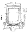
- the exhaust gas purifying device 1 includes a cylindrical casing 21.
- An exhaust gas purifying filter 13 is accommodated in the casing 21.
- the filter 13 will hereafter be explained.
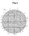
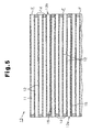
- the filter 13 of the first embodiment is formed by bundling a plurality of sintered honeycomb bodies F as one body.
- the sintered honeycomb bodies F located in the middle portion of the filter 13 are shaped as square rods.
- a plurality of sintered honeycomb bodies F that are shaped differently, or unlike the square rods, are arranged around the honeycomb bodies F that are shaped as the square rods. Accordingly, the filter 13 as a whole is shaped as a cylinder.
- each of the sintered honeycomb bodies F is formed from a sintered body of porous silicon carbide (SiC), which is a type of sintered ceramic body.
- SiC porous silicon carbide
- a sintered body of silicon nitride or sialon or alumina or cordierite may be selected.
- a plurality of through holes 11, each of which has a substantially square cross-sectional shape, are formed in each of the sintered honeycomb bodies F and are arranged regularly in an axial direction. The through holes 11 are spaced from one another by cell walls 12. An opening of each through hole 11 is sealed by a plug 14 (in this embodiment, a sintered body of porous silicon carbide) at one of end surfaces 13a, 13b.
- Each of the end surfaces 13a, 13b as a whole thus presents a diced pattern.
- a number of cells each having a square cross-sectional shape are formed in each sintered honeycomb body F. Approximately half of the cells open at the upstream end surface 13a, while the remaining cells open at the downstream end surface 13b.
- the sintered honeycomb bodies F are bound together by an adhesive 15 at the outer peripheral surfaces.
- the adhesive 15 serves to compensate thermal expansion of the sintered honeycomb bodies F. In other words, the adhesive 15 prevents cracks from being caused by thermal stress.
- a heat resistant ceramic adhesive in which ceramic fibers are dispersed is used as the adhesive 15. It is preferred that silicon carbide powders, in addition to the ceramic fibers, are dispersed in the adhesive 15.
- the casing 21, which accommodates the filter 13, is configured by a plurality of metal tubular members. More specifically, in the first embodiment, three members including a heater case 22, an inner case 23, and an outer case 24 (all formed of SUS304) configure the casing 21.
- the heater case 22, serving as a heating means accommodating case, forms a portion of a heater unit.
- the inner case 23 forms a portion of a filter unit.
- the heater case 22 defines a sealed space for preventing exhaust gas from entering the heater case 22.
- the heater case 22 thus provides a heat insulating effect.
- a mat-shaped heat insulating material 8 the main component of which is ceramic fibers, is packed in the space of the heater case 22. This improves the heat insulating effect.
- Each of the inner case 23 and the outer case 24 has a cylindrical shape.
- the inner case 23, which is accommodated in the outer case 22, is smaller than the outer case 24 (the longitudinal dimension and the diameter of the inner case 23 are smaller than those of the outer case 24). Therefore, when the cases are assembled, a clearance C1 having a constant dimension is defined between the outer peripheral surface of the inner case 23 and the inner peripheral surface of the outer case 24, which is arranged around the inner case 23. In the first embodiment, the dimension of the clearance C1 is approximately 1 to 5 millimeters.
- a flange 25 of the inner case 23 serves also as a fluid blocking member that blocks communication between the space including the upstream end surface 13a of the filter 13 and the clearance C1.
- the flange 25 projects from the outer peripheral surface of an upstream end portion of the inner case 23.
- a flange 26 projects from the outer peripheral surface of an upstream end portion of the outer case 24.
- the flanges 25, 26 are designed to define equal outer diameters.
- a plurality of bolt holes 28 are formed in the flange 25 and are spaced from adjacent ones at certain intervals.
- a plurality of bolt holes 29 are formed in the flange 26 and are spaced from adjacent ones at certain intervals.
- Attachment bolts 27 are passed through the bolt holes 28, 29.
- the bolt holes 29 of the flange 25 are located at positions corresponding to the bolt holes 28 of the flange 26.
- a plurality of bolt holes 31 are formed in a downstream end surface of the heater case 22 at positions corresponding to the bolt holes 28, 29.
- the mat-shaped heat insulating material 17 containing ceramic fibers is wrapped around the filter 13.
- the filter 13 is held in the inner case 23. That is, the inner case 23 supports the outer peripheral surface of the filter 13 through the heat insulating material 17.
- a filter support 30 projects from the inner peripheral surface of the downstream end of the inner case 23 and extends along the entire circumference. The filter support 30 is abutted by an outer peripheral portion of the downstream end surface 13b of the filter 13. This structure prevents the filter 13 from falling from the inner case 23 to the downstream side.
- a support piece 30a is attached to the inner peripheral surface of the upstream end portion of the inner case 23 and extends along the entire circumference.
- the support piece 30a is abutted by an outer peripheral portion of the upstream end surface 13a of the filter 13. This structure prevents the filter 13 from falling from the inner case 23 to the upstream side. Further, the heat insulating material 17 is prevented from being displaced.
- a plurality of support pieces 30a may be deployed as spaced from adjacent ones at predetermined angular intervals.
- a coupling portion 32 projects from a middle portion of the upstream end surface of the heater case 22 and is coupled with a downstream end of the first exhaust pipe 6. Further, a coupling portion 33 projects from a middle portion of the downstream end surface of the outer case 24 and is coupled with an upstream end of the second exhaust pipe 7.
- the heater case 22 a component of the casing 21, accommodates a heater 34 and a temperature detector 35.
- the heater 34 serves as an electric heating means for regenerating the filter and is located at an upstream position with respect to the filter 13.
- an AC heater is used as the heater 34.
- the heater 34 is formed by winding a cable spirally. More specifically, the cable includes a conductive core of a nichrome wire covered by a sheath of magnesia, which presents improved insulating performance.
- the heater 34 is opposed to the upstream end surface 13a of the filter 13 and is spaced from the upstream end surface 13a at a certain interval.
- Two end portions 34a of the heater 34 extend through an outer peripheral portion of the heater case 22 to the exterior of the casing 21.
- the core projecting from each of the end portions 34a of the heater 34 is electrically connected to a connector through a glass tube.
- the connector as shown in Fig. 1, is electrically connected to a driver circuit of a control unit U1 controlling the regenerating operation of the filter 13.
- the control unit U1 operates to supply power to the heater 34 from an external power source B1. This enables the heater 34 to generate heat from the entire portion such that the temperature rises to 800 to 900 degrees Celsius.
- a punching plate 38 serving as a porous heat reflector is disposed at an upstream position with respect to the heater 34.
- the punching plate 38 is a disk-shaped plate member and is formed of stainless steel (SUS304) in the first embodiment.
- the outer periphery of the punching plate 38 is bonded with the inner peripheral surface of the heater case 22 through, for example, welding. The punching plate 38 is thus secured to the heater case 22. Further, the heater 34 is fixed to the punching plate 38 by a fixing tool 37.
- a number of through holes 38a extend through the punching plate 38.
- the through holes 38a are arranged regularly to cover substantially the entire area of the punching plate 38. Therefore, after being discharged from the first exhaust pipe 6, exhaust gas passes through the through holes 38a to reach the filter 13. Further, the punching plate 38 reflects the heat generated by the heater 34, preventing the heat from being released to the exterior. In other words, the heat reflected by the punching plate 38 is supplied to the filter 13 as radiation heat. The filter 13 is thus efficiently heated.
- a ceramic foam reflector 39 serving as another porous heat reflector is disposed at the downstream side of the filter 13, as illustrated in Fig. 2.
- the ceramic foam reflector 39 is supported by a heat reflector support 40, which projects from the inner peripheral surface of the outer case 24 and extends along the entire circumference.
- the ceramic foam reflector 39 is a porous body formed of aluminum nitride or the like and presents fluid permeability and heat insulating properties. Therefore, like the upstream side of the filter 13, a heat insulating effect is ensured at the downstream side of the filter 13.
- the temperature detector 35 is deployed in the vicinity of the heater 34.
- the temperature detector 35 is a rod-shaped body, and a temperature detecting portion 35a is formed at a distal end of the temperature detector 35.
- the temperature detector 35 of this embodiment includes a sheath thermocouple covered by a protecting pipe formed of stainless steel or the like.
- the temperature detecting portion 35a is exposed from a distal end of the covered sheath thermocouple.
- the temperature detecting portion 35a is placed in the space defined by the cable spirally wound in the heater 34.
- the temperature detector 35 is electrically connected to the control unit U1.
- the casing 21 accommodating the filter 13 is deployed in the exhaust gas passage, or between the first exhaust pipe 6 and the second exhaust pipe 7.
- exhaust gas is sent to the interior of the casing 21. That is, after being discharged from the first exhaust pipe 6, the exhaust gas flows first into the cells opening at the upstream end surface 13a of the filter 13. The gas then permeates the cell walls 12 and reaches the adjacent cells, which open at the downstream end surface 13b of the filter 13. Further, through the openings of the cells, the exhaust gas is discharged from the downstream end surface 13b of the filter 13.
- the soot contained in the exhaust gas is not permitted to permeate the cell walls 12 and is trapped in the cells.
- the exhaust gas is purified before being discharged from the downstream end surface 13b of the filter 13.
- the purified gas further flows in the second exhaust pipe 7 and is eventually released to the atmosphere.
- the heater 34 is powered to heat the filter 13 and supporting air is supplied such that the soot is burned and removed. More specifically, the soot in the vicinity of the upstream end surface 13a of the filter 13 starts to burn. Burning of the soot is gradually spread to the downstream end surface 13b. By maintaining the soot burning for a certain time period, the filter 13 is regenerated.
- the first embodiment has the following effects.
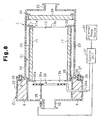
- a flange 41 projects from the outer peripheral surface of the downstream end portion of the inner case 23 and extends along the entire circumference.
- the flange 41 serving as a fluid blocking member blocks communication between the space including the downstream end surface 13b of the filter 13 and the clearance C1.
- This structure further reduces the heat energy loss caused by the heat transmission from the exhaust gas to the outer case 24, as compared to the first embodiment. This effect is brought about by the fact that a heat insulating air layer more preferable than that of the first embodiment is formed in the clearance C1. Therefore, costs are further saved.
- the filter 13 is further securely fixed as long as the outer periphery of the flange 41 is held in contact with the inner peripheral surface of the outer case 24, as shown in Fig. 6.
- a clearance is defined between the flange 41 and the inner peripheral surface of the outer case 24.
- the clearance makes it possible to remove the inner case 23 smoothly from the outer case 24, even if the dimensions of the inner case 23 are changed due to thermal expansion.
- the casing 21 includes an additional outer case 42, other than the outer case 24.
- the casing 21 thus has a triple structure.
- the additional outer case 42 is arranged between the outer case 24 and the inner case 23.
- This structure has two clearances C1, each of which serves as a heat insulating air layer.
- a flange 43 projects from the outer peripheral surface of the upstream end portion of the outer case 42. The flange 43 is deployed as clamped between the flanges 25, 26.
- a flange 41a serving as a fluid blocking member projects from the inner peripheral surface of the outer case 24.
- the flange 41a is engaged with the filter support 30 of the inner case 23.
- the communication between the space including the downstream end surface 13b of the filter 13 and the clearance C1 is blocked by the flange 41a.
- the fourth embodiment is not provided with the punching plate 38 such that the configuration becomes simple.
- the support piece 30a which is otherwise formed at the upstream end portion of the inner case 23, is not provided, as is clear from comparison with the first embodiment.
- the fifth embodiment thus has the operational effects of the first embodiment, except for that of the support piece 30a.
- the exhaust gas purifying devices of the illustrated embodiments were subjected to an operational test.
- One cycle of the test was defined by sending exhaust gas to each of the devices, heating the filter by the heater, and supplying supporting air for burning the soot.
- the test included ten cycles.
- the test results are shown in Table 1.
- the longitudinal dimension of the filter 13 was 150 millimeters.
- Embodiment Drawing Upstream Blocker Downstream Blocker Structure Support Piece Punching Plate Temperature Difference (C°) Crack Insulator Corrosion Size 1 Fig. 2 Formed None Double Formed Formed 30 None 0 2 Fig. 6 Formed Formed Double Formed Formed 20 None 0 3 Fig. 7 Formed None Triple Formed Formed 26 None 0 4 Fig. 8 Formed Formed Double Formed None 40 None 0 5 Fig. 9 Formed None Double None Formed 30 None 15 Comparative - None None Single None 150 Detected 15
- the temperature difference indicates the temperature difference between the middle portion and the outer peripheral portion of the filter 13.
- the insulator corrosion size indicates the size of the portion of the heat insulating material lost due to corrosion in the test. Detection of cracks was conducted visually after the test was completed.
- a purifying device prepared as the comparative example did not include any of the inner case, the upstream blocking member, the downstream blocking member, the support piece, and the punching plate. This purifying device was also subjected to the operational test.
- the temperature difference between the middle portion and the outer peripheral portion of the filter was enlarged, causing cracks.
- the temperature difference was relatively small in the first to fifth embodiments. Therefore, no crack was detected, and the durability was improved.
- the support piece 30a operated efficiently for preventing the heat insulating material from being corroded.
- the punching plate 38 and the ceramic foam reflector 39 are employed as the porous heat reflectors.
- the heat reflectors are not limited to those of the embodiments but may be, for example, a body formed of metal meshes or ceramic fibers.
- the ceramic foam reflector 39 which is provided at the downstream side of the filter 13, may be replaced by the punching plate 38. Further, the ceramic foam reflector 39 may be omitted. In this manner, the number of the components of the exhaust gas purifying device 1 is decreased.
- the heater 34 does not necessarily have to be an AC heater but may be, for example, a DC heater. Further, the electric heating means such as the electric heater may be replaced by a non-electric heating means such as a burner.
- the fluid blocking member does not necessarily have to be the flange 25, which projects from the outer peripheral surface of the end of the inner case 23.
- the fluid blocking member may be a different structure provided separately from the inner case 23.
- the flange 25 may be fixed to the outer case 24, which is the outermost layer, through, for example, welding, such that the flange 25 is prohibited from being attached to or detached from the outer case 24.
Landscapes
- Engineering & Computer Science (AREA)
- Chemical & Material Sciences (AREA)
- Combustion & Propulsion (AREA)
- Mechanical Engineering (AREA)
- General Engineering & Computer Science (AREA)
- Processes For Solid Components From Exhaust (AREA)
Abstract
An exhaust gas purifying device includes a tubular casing
21 arranged in exhaust passages 6, 7 of an internal combustion
engine. A filter 13 is held in the casing 21. The filter 13
collects and burns particulates contained in the exhaust gas
discharged by the internal combustion engine. The casing 21
has a double structure including an inner case 23 supporting
an outer peripheral surface of the filter 13 and an outer case
24 arranged around the inner case 23. The inner and outer
cases 23, 24 are spaced from each other with a clearance C1
defined between the cases 23, 24.
Description
The present invention relates to exhaust gas purifying
devices for purifying exhaust gas discharged by internal
combustion engines including diesel engines and casing
structures for the devices.
Conventionally, a number of exhaust gas purifying devices
have been proposed. The devices are configured by
accommodating a ceramic honeycomb filter for purifying exhaust
gas in a metal tubular casing, which is disposed in an exhaust
passage of a diesel engine. As the filter is used for a
relatively long time, the filter collects soot (diesel
particulates) from the exhaust gas. The soot is deposited in
the filter and gradually increases the engine load. If this
is the case, the filter is heated to the ignition temperature
of the soot (600 to 630 degrees Celsius) by a heating means
such as a heater or burner. The soot is thus burned and
removed such that the filter is regenerated.
However, conventional exhaust gas purifying devices have
the following problems.
That is, when the filter is heated by the heating means,
the heat is transmitted to a different component (for example,
the casing) that is held in contact with the filter. The heat
thus escapes to the exterior of the filter, hampering the
heating of the filter. This increases the energy needed to
heat the filter to the soot ignition temperature and raises
costs. Further, if an electric heater is used as the heating
means, an increased electric load is applied to the battery,
which accelerates the battery consumption.
In addition, a temperature difference is caused between
the middle portion of the filter and an outer peripheral
portion of the filter. Therefore, if the honeycomb filter is
formed of, for example, porous silicon carbide, an increased
thermal stress is generated in the filter. In this case, the
filter has a tendency to crack, which is damaging to the
filter. Moreover, in conventional devices, replacement of the
filter is complicated, making it difficult to maintain the
devices.
The present invention is for solving the above problems.
Accordingly, it is an objective of the invention to provide an
exhaust gas purifying device that saves costs by decreasing
energy loss and suppressing damage to the filter, as well as a
casing structure for the device.
To solve the above problems, the gist of a first
embodiment of the present invention is an exhaust gas
purifying device comprising a tubular casing disposed in an
exhaust passage of an internal combustion engine and a filter
accommodated in the casing for collecting, burning, and
removing particulates contained in the exhaust gas discharged
by the internal combustion engine. The device is
characterized in that the casing has a multiple case structure
including an inner case supporting an outer peripheral surface
of the filter and at least one outer case arranged around the
inner case, and that the inner and outer cases are spaced from
each other with a clearance defined between the cases.
The gist of a second embodiment is an exhaust gas
purifying device comprising a tubular casing disposed in an
exhaust passage of an internal combustion engine and a filter
accommodated in the casing for collecting, burning, and
removing particulates contained in the exhaust gas discharged
by the internal combustion engine. The device is
characterized in that the casing has a double structure
including an inner case supporting an outer peripheral surface
of the filter and an outer case arranged around the inner
case, and that the inner and outer cases are spaced from each
other with a clearance defined between the cases.
It is desirable that a fluid blocking member is provided
at an upstream end portion of the inner case for blocking
communication between a space including an upstream end
surface of the filter and the clearance.
A fluid blocking member may be provided at a downstream
side of the inner case and between the inner case and the
outer case for blocking communication between a space
including a downstream end surface of the filter and the
clearance.
The fluid blocking member may be a flange projecting from
an outer peripheral surface of an end of the inner case. The
flange may be secured to an outermost component of the outer
case in an attachable or detachable manner.
A heater for regenerating the filter may be disposed at
an upstream position with respect to the filter. Further, a
porous heat reflector may be arranged at a further upstream
position with respect to the heater.
The gist of a third embodiment is a casing structure of
an exhaust gas purifying device having a multiple structure
including an inner case supporting an outer peripheral surface
of a filter for collecting, burning, and removing particulates
contained in the exhaust gas discharged by an internal
combustion engine and at least one outer case arranged around
the inner case. The casing structure is characterized in that
the inner and outer cases are spaced from each other with a
clearance defined between the cases.
In each of the above-described embodiments, the outer
peripheral surface of the filter is held in contact with the
inner case. However, the clearance is defined between the
inner case and the outer case. Therefore, in other words, a
heat insulating air layer is ensured between the inner and
outer cases. The heat transmission from the inner case to the
outer case is thus hampered. This prevents the heat from
escaping to the exterior of the filter such that the
temperature of the filter is efficiently raised. That is, the
exhaust gas purifying device reduces energy loss and thus
saves costs. Further, since the heat is prevented from
escaping from the outer peripheral portion of the filter, the
temperature difference between the middle portion and the
outer peripheral portion of the filter hardly occurs. As a
result, a relatively large thermal stress, which leads to
cracks damaging the filter, is avoided.
If the fluid blocking member is provided at the upstream
end portion of the inner case, communication between the space
including the upstream end surface of the filter and the
clearance is blocked. Therefore, a relatively hot exhaust gas
does not flow into the clearance in which the heat insulating
air layer is formed. This structure reduces heat energy loss
caused by heat transmission from the exhaust gas to the outer
case. The costs are thus further saved. Further, the exhaust
gas does not bypass the filter or reach the downstream side of
the filter without being purified. The purifying efficiency
is thus prevented from being lowered.
If the fluid blocking member is provided at the
downstream end portion of the inner case, communication
between the space including the downstream end surface of the
filter and the clearance is blocked. This structure further
reduces the heat energy loss caused by the heat transmission
from the exhaust gas to the outer case. The costs are thus
further saved.
If the fluid blocking member is configured by the flange,
the flange serves also as a portion to which the inner case is
secured. This avoids an increase in the number of the parts
and complication of the structure. Further, the filter may be
removed from the outer case in a state accommodated in the
inner case. The replacement of the filter thus becomes
relatively easy, as compared to a conventional case. As a
result, maintenance is facilitated.
If a heater for regenerating the filter and heat
reflector are provided, the heat of the heater is reflected by
the heat reflector. The heat energy loss of the heater is
thus decreased, and the filter is heated efficiently.
Further, since the heat reflector is porous, the flow of the
exhaust gas to the filter is not hampered.
An exhaust gas purifying device 1 according to a first
embodiment of the present invention will hereafter be
described with reference to Figs. 1 to 5.
As illustrated in Fig. 1, the exhaust gas purifying
device 1 purifies exhaust gas discharged by a diesel engine 2,
which serves as an internal combustion engine. The diesel
engine 2 includes a plurality of non-illustrated cylinders. A
branch 4 of a metal exhaust manifold 3 is coupled to each of
the cylinders. The branches 4 are connected to a manifold
body 5. Thus, the exhaust gas sent from each of the cylinders
is concentrated at one point.
A first exhaust pipe 6 and a second exhaust pipe 7, which
are formed of metal, are disposed at a downstream side of the
exhaust manifold 3. An upstream end of the first exhaust pipe
6 is coupled to the manifold body 5. The exhaust gas
purifying device 1 is located between the first exhaust pipe 6
and the second exhaust pipe 7.
With reference to Fig. 2, the exhaust gas purifying
device 1 includes a cylindrical casing 21. An exhaust gas
purifying filter 13 is accommodated in the casing 21. The
filter 13 will hereafter be explained.
Since the filter 13 is used for removing diesel
particulates, the filter 13 is called also as a diesel
particulate filter (DPF). The filter 13 of the first
embodiment, as shown in Figs. 4 and 5, is formed by bundling a
plurality of sintered honeycomb bodies F as one body. The
sintered honeycomb bodies F located in the middle portion of
the filter 13 are shaped as square rods. A plurality of
sintered honeycomb bodies F that are shaped differently, or
unlike the square rods, are arranged around the honeycomb
bodies F that are shaped as the square rods. Accordingly, the
filter 13 as a whole is shaped as a cylinder.
In the first embodiment, each of the sintered honeycomb
bodies F is formed from a sintered body of porous silicon
carbide (SiC), which is a type of sintered ceramic body.
However, other than the sintered body of silicon carbide, a
sintered body of silicon nitride or sialon or alumina or
cordierite may be selected. A plurality of through holes 11,
each of which has a substantially square cross-sectional
shape, are formed in each of the sintered honeycomb bodies F
and are arranged regularly in an axial direction. The through
holes 11 are spaced from one another by cell walls 12. An
opening of each through hole 11 is sealed by a plug 14 (in
this embodiment, a sintered body of porous silicon carbide) at
one of end surfaces 13a, 13b. Each of the end surfaces 13a,
13b as a whole thus presents a diced pattern. As a result, a
number of cells each having a square cross-sectional shape are
formed in each sintered honeycomb body F. Approximately half
of the cells open at the upstream end surface 13a, while the
remaining cells open at the downstream end surface 13b.
As shown in Figs. 4 and 5, the sintered honeycomb bodies
F are bound together by an adhesive 15 at the outer peripheral
surfaces. The adhesive 15 serves to compensate thermal
expansion of the sintered honeycomb bodies F. In other words,
the adhesive 15 prevents cracks from being caused by thermal
stress. In the first embodiment, a heat resistant ceramic
adhesive in which ceramic fibers are dispersed is used as the
adhesive 15. It is preferred that silicon carbide powders, in
addition to the ceramic fibers, are dispersed in the adhesive
15.
With reference to Figs. 2 and 3, the casing 21, which
accommodates the filter 13, is configured by a plurality of
metal tubular members. More specifically, in the first
embodiment, three members including a heater case 22, an inner
case 23, and an outer case 24 (all formed of SUS304) configure
the casing 21. The heater case 22, serving as a heating means
accommodating case, forms a portion of a heater unit. The
inner case 23 forms a portion of a filter unit.
The heater case 22 defines a sealed space for preventing
exhaust gas from entering the heater case 22. The heater case
22 thus provides a heat insulating effect. A mat-shaped heat
insulating material 8, the main component of which is ceramic
fibers, is packed in the space of the heater case 22. This
improves the heat insulating effect.
Each of the inner case 23 and the outer case 24 has a
cylindrical shape. The inner case 23, which is accommodated
in the outer case 22, is smaller than the outer case 24 (the
longitudinal dimension and the diameter of the inner case 23
are smaller than those of the outer case 24). Therefore, when
the cases are assembled, a clearance C1 having a constant
dimension is defined between the outer peripheral surface of
the inner case 23 and the inner peripheral surface of the
outer case 24, which is arranged around the inner case 23. In
the first embodiment, the dimension of the clearance C1 is
approximately 1 to 5 millimeters. A flange 25 of the inner
case 23 serves also as a fluid blocking member that blocks
communication between the space including the upstream end
surface 13a of the filter 13 and the clearance C1.
The flange 25 projects from the outer peripheral surface
of an upstream end portion of the inner case 23. In the same
manner, a flange 26 projects from the outer peripheral surface
of an upstream end portion of the outer case 24. The flanges
25, 26 are designed to define equal outer diameters. A
plurality of bolt holes 28 are formed in the flange 25 and are
spaced from adjacent ones at certain intervals. In the same
manner, a plurality of bolt holes 29 are formed in the flange
26 and are spaced from adjacent ones at certain intervals.
Attachment bolts 27 are passed through the bolt holes 28, 29.
The bolt holes 29 of the flange 25 are located at positions
corresponding to the bolt holes 28 of the flange 26. In the
same manner, a plurality of bolt holes 31 are formed in a
downstream end surface of the heater case 22 at positions
corresponding to the bolt holes 28, 29. Thus, if the bolts 27
are passed through the corresponding bolt holes 28, 29, 31 and
fastened as such, the cases 22, 23, 24 are fixed to each other
to form one body, or the casing 21. If the bolts 27 are
removed from the bolt holes 28, 29, 31, the casing 21 is
separated into three parts. In other words, it may be
understood that the flange 25 of the inner case 23 is secured
to the flange 26 of the outer case 24 in an attachable or
detachable manner.
The mat-shaped heat insulating material 17 containing
ceramic fibers is wrapped around the filter 13. In this
state, the filter 13 is held in the inner case 23. That is,
the inner case 23 supports the outer peripheral surface of the
filter 13 through the heat insulating material 17. A filter
support 30 projects from the inner peripheral surface of the
downstream end of the inner case 23 and extends along the
entire circumference. The filter support 30 is abutted by an
outer peripheral portion of the downstream end surface 13b of
the filter 13. This structure prevents the filter 13 from
falling from the inner case 23 to the downstream side.
A support piece 30a is attached to the inner peripheral
surface of the upstream end portion of the inner case 23 and
extends along the entire circumference. The support piece 30a
is abutted by an outer peripheral portion of the upstream end
surface 13a of the filter 13. This structure prevents the
filter 13 from falling from the inner case 23 to the upstream
side. Further, the heat insulating material 17 is prevented
from being displaced. A plurality of support pieces 30a may
be deployed as spaced from adjacent ones at predetermined
angular intervals.
A coupling portion 32 projects from a middle portion of
the upstream end surface of the heater case 22 and is coupled
with a downstream end of the first exhaust pipe 6. Further, a
coupling portion 33 projects from a middle portion of the
downstream end surface of the outer case 24 and is coupled
with an upstream end of the second exhaust pipe 7.
As illustrated in Figs. 1 and 2, the heater case 22, a
component of the casing 21, accommodates a heater 34 and a
temperature detector 35. The heater 34 serves as an electric
heating means for regenerating the filter and is located at an
upstream position with respect to the filter 13. In the first
embodiment, an AC heater is used as the heater 34. The heater
34 is formed by winding a cable spirally. More specifically,
the cable includes a conductive core of a nichrome wire
covered by a sheath of magnesia, which presents improved
insulating performance.
The heater 34 is opposed to the upstream end surface 13a
of the filter 13 and is spaced from the upstream end surface
13a at a certain interval. Two end portions 34a of the heater
34 extend through an outer peripheral portion of the heater
case 22 to the exterior of the casing 21. The core projecting
from each of the end portions 34a of the heater 34 is
electrically connected to a connector through a glass tube.
The connector, as shown in Fig. 1, is electrically connected
to a driver circuit of a control unit U1 controlling the
regenerating operation of the filter 13. Thus, when
necessary, the control unit U1 operates to supply power to the
heater 34 from an external power source B1. This enables the
heater 34 to generate heat from the entire portion such that
the temperature rises to 800 to 900 degrees Celsius.
With reference to Fig. 2, a punching plate 38 serving as
a porous heat reflector is disposed at an upstream position
with respect to the heater 34. The punching plate 38 is a
disk-shaped plate member and is formed of stainless steel
(SUS304) in the first embodiment. The outer periphery of the
punching plate 38 is bonded with the inner peripheral surface
of the heater case 22 through, for example, welding. The
punching plate 38 is thus secured to the heater case 22.
Further, the heater 34 is fixed to the punching plate 38 by a
fixing tool 37.
A number of through holes 38a extend through the punching
plate 38. The through holes 38a are arranged regularly to
cover substantially the entire area of the punching plate 38.
Therefore, after being discharged from the first exhaust pipe
6, exhaust gas passes through the through holes 38a to reach
the filter 13. Further, the punching plate 38 reflects the
heat generated by the heater 34, preventing the heat from
being released to the exterior. In other words, the heat
reflected by the punching plate 38 is supplied to the filter
13 as radiation heat. The filter 13 is thus efficiently
heated.
A ceramic foam reflector 39 serving as another porous
heat reflector is disposed at the downstream side of the
filter 13, as illustrated in Fig. 2. In the first embodiment,
the ceramic foam reflector 39 is supported by a heat reflector
support 40, which projects from the inner peripheral surface
of the outer case 24 and extends along the entire
circumference. The ceramic foam reflector 39 is a porous body
formed of aluminum nitride or the like and presents fluid
permeability and heat insulating properties. Therefore, like
the upstream side of the filter 13, a heat insulating effect
is ensured at the downstream side of the filter 13.
With reference to Fig. 2, the temperature detector 35 is
deployed in the vicinity of the heater 34. The temperature
detector 35 is a rod-shaped body, and a temperature detecting
portion 35a is formed at a distal end of the temperature
detector 35. The temperature detector 35 of this embodiment
includes a sheath thermocouple covered by a protecting pipe
formed of stainless steel or the like. The temperature
detecting portion 35a is exposed from a distal end of the
covered sheath thermocouple. The temperature detecting
portion 35a is placed in the space defined by the cable
spirally wound in the heater 34. The temperature detector 35
is electrically connected to the control unit U1.
The operation of the exhaust gas purifying device 1
configured as described above will hereafter be explained.
The casing 21 accommodating the filter 13 is deployed in
the exhaust gas passage, or between the first exhaust pipe 6
and the second exhaust pipe 7. In this state, if the engine 2
is started, exhaust gas is sent to the interior of the casing
21. That is, after being discharged from the first exhaust
pipe 6, the exhaust gas flows first into the cells opening at
the upstream end surface 13a of the filter 13. The gas then
permeates the cell walls 12 and reaches the adjacent cells,
which open at the downstream end surface 13b of the filter 13.
Further, through the openings of the cells, the exhaust gas is
discharged from the downstream end surface 13b of the filter
13.
However, the soot contained in the exhaust gas is not
permitted to permeate the cell walls 12 and is trapped in the
cells. As a result, the exhaust gas is purified before being
discharged from the downstream end surface 13b of the filter
13. The purified gas further flows in the second exhaust pipe
7 and is eventually released to the atmosphere. Afterwards,
the heater 34 is powered to heat the filter 13 and supporting
air is supplied such that the soot is burned and removed.
More specifically, the soot in the vicinity of the upstream
end surface 13a of the filter 13 starts to burn. Burning of
the soot is gradually spread to the downstream end surface
13b. By maintaining the soot burning for a certain time
period, the filter 13 is regenerated.
Accordingly, the first embodiment has the following
effects.
Other embodiments of the present invention will hereafter
be described.
In a second embodiment illustrated in Fig. 6, a flange 41
projects from the outer peripheral surface of the downstream
end portion of the inner case 23 and extends along the entire
circumference. In this embodiment, the flange 41 serving as a
fluid blocking member blocks communication between the space
including the downstream end surface 13b of the filter 13 and
the clearance C1. This structure further reduces the heat
energy loss caused by the heat transmission from the exhaust
gas to the outer case 24, as compared to the first embodiment.
This effect is brought about by the fact that a heat
insulating air layer more preferable than that of the first
embodiment is formed in the clearance C1. Therefore, costs
are further saved. In addition, the filter 13 is further
securely fixed as long as the outer periphery of the flange 41
is held in contact with the inner peripheral surface of the
outer case 24, as shown in Fig. 6.
Further, it is desirable that a clearance is defined
between the flange 41 and the inner peripheral surface of the
outer case 24. The clearance makes it possible to remove the
inner case 23 smoothly from the outer case 24, even if the
dimensions of the inner case 23 are changed due to thermal
expansion.
In a third embodiment illustrated in Fig. 7, the casing
21 includes an additional outer case 42, other than the outer
case 24. The casing 21 thus has a triple structure. The
additional outer case 42 is arranged between the outer case 24
and the inner case 23. This structure has two clearances C1,
each of which serves as a heat insulating air layer. Further,
a flange 43 projects from the outer peripheral surface of the
upstream end portion of the outer case 42. The flange 43 is
deployed as clamped between the flanges 25, 26.
In a fourth embodiment illustrated in Fig. 8, a flange
41a serving as a fluid blocking member projects from the inner
peripheral surface of the outer case 24. The flange 41a is
engaged with the filter support 30 of the inner case 23. The
communication between the space including the downstream end
surface 13b of the filter 13 and the clearance C1 is blocked
by the flange 41a. This structure further reduces the heat
energy loss caused by the heat transmission from the exhaust
gas to the outer case 24, as compared to a comparative example
(which will be described later).
Also, the fourth embodiment is not provided with the
punching plate 38 such that the configuration becomes simple.
In a fifth embodiment illustrated in Fig. 9, the support
piece 30a, which is otherwise formed at the upstream end
portion of the inner case 23, is not provided, as is clear
from comparison with the first embodiment. The fifth
embodiment thus has the operational effects of the first
embodiment, except for that of the support piece 30a.
The exhaust gas purifying devices of the illustrated
embodiments were subjected to an operational test. One cycle
of the test was defined by sending exhaust gas to each of the
devices, heating the filter by the heater, and supplying
supporting air for burning the soot. The test included ten
cycles. The test results are shown in Table 1. The
longitudinal dimension of the filter 13 was 150 millimeters.
| Embodiment | Drawing | Upstream Blocker | Downstream Blocker | Structure | Support Piece | Punching Plate | Temperature Difference (C°) | Crack | | |
| 1 | Fig. 2 | Formed | None | Double | Formed | Formed | 30 | | 0 | |
| 2 | Fig. 6 | Formed | Formed | Double | Formed | Formed | 20 | | 0 | |
| 3 | Fig. 7 | Formed | None | Triple | Formed | Formed | 26 | | 0 | |
| 4 | Fig. 8 | Formed | Formed | Double | | None | 40 | | 0 | |
| 5 | Fig. 9 | Formed | None | Double | None | Formed | 30 | | 15 | |
| Comparative | - | None | None | Single | None | None | 150 | Detected | 15 |
In Table 1, the temperature difference indicates the
temperature difference between the middle portion and the
outer peripheral portion of the filter 13. The insulator
corrosion size indicates the size of the portion of the heat
insulating material lost due to corrosion in the test.
Detection of cracks was conducted visually after the test was
completed. A purifying device prepared as the comparative
example did not include any of the inner case, the upstream
blocking member, the downstream blocking member, the support
piece, and the punching plate. This purifying device was also
subjected to the operational test.
As indicated clearly in Table 1, in the comparative
example, the temperature difference between the middle portion
and the outer peripheral portion of the filter was enlarged,
causing cracks. In contrast, the temperature difference was
relatively small in the first to fifth embodiments.
Therefore, no crack was detected, and the durability was
improved.
Further, as is clear from comparison among the
comparative example, the first embodiment, and the fifth
embodiment, the support piece 30a operated efficiently for
preventing the heat insulating material from being corroded.
The present invention is not restricted to the
illustrated embodiments but may be embodied in the following
forms.
In the illustrated embodiments, the punching plate 38 and
the ceramic foam reflector 39 are employed as the porous heat
reflectors. However, the heat reflectors are not limited to
those of the embodiments but may be, for example, a body
formed of metal meshes or ceramic fibers.
The ceramic foam reflector 39, which is provided at the
downstream side of the filter 13, may be replaced by the
punching plate 38. Further, the ceramic foam reflector 39 may
be omitted. In this manner, the number of the components of
the exhaust gas purifying device 1 is decreased.
The heater 34 does not necessarily have to be an AC
heater but may be, for example, a DC heater. Further, the
electric heating means such as the electric heater may be
replaced by a non-electric heating means such as a burner.
The fluid blocking member does not necessarily have to be
the flange 25, which projects from the outer peripheral
surface of the end of the inner case 23. The fluid blocking
member may be a different structure provided separately from
the inner case 23.
The flange 25 may be fixed to the outer case 24, which is
the outermost layer, through, for example, welding, such that
the flange 25 is prohibited from being attached to or detached
from the outer case 24.
Claims (12)
- An exhaust gas purifying device comprising a tubular casing disposed in an exhaust passage of an internal combustion engine and a filter accommodated in the casing for collecting, burning, and removing particulates contained in the exhaust gas discharged by the internal combustion engine, the device being characterized in that:the casing has a multiple structure including an inner case supporting an outer peripheral surface of the filter and at least one outer case arranged around the inner case, and the inner and outer cases are spaced from each other with a clearance defined between the cases.
- An exhaust gas purifying device.comprising a tubular casing disposed in an exhaust passage of an internal combustion engine and a filter accommodated in the casing for collecting, burning, and removing particulates contained in the exhaust gas discharged by the internal combustion engine, the device being characterized in that:the casing has a double structure including an inner case supporting an outer peripheral surface of the filter and an outer case arranged around the inner case, and the inner and outer cases are spaced from each other with a clearance defined between the cases.
- The exhaust gas purifying device according to Claims 1 or 2, characterized in that a fluid blocking member is formed at an upstream end portion of the inner case for blocking communication between a space including an upstream end surface of the filter and the clearance.
- The exhaust gas purifying device according to any one of Claims 1 to 3, characterized in that a support piece is provided at an upstream side of the inner case.
- The exhaust gas purifying device according to Claim 3, characterized in that a fluid blocking member is provided at a downstream side of the inner case and between the inner case and the outer case for blocking communication between a space including a downstream end surface of the filter and the clearance.
- The exhaust gas purifying device according to any one of Claims 3 to 5, characterized in that the fluid blocking member is a flange projecting from an outer peripheral surface of an end of the inner case, and the flange is secured to an outermost component of the outer case in an attachable or detachable manner.
- The exhaust gas purifying device according to any one of Claims 1 to 6, characterized in that a heater for regenerating the filter is disposed at an upstream position with respect to the filter, and a porous heat reflector is arranged at a further upstream position with respect to the heater.
- A casing structure of an exhaust gas purifying device having a multiple structure including an inner case supporting an outer peripheral surface of a filter for collecting, burning, and removing particulates contained in the exhaust gas discharged by an internal combustion engine and at least one outer case arranged around the inner case, the casing structure being characterized in that the inner and outer cases are spaced from each other with a clearance defined between the cases.
- The exhaust gas purifying device according to any one of Claims 1 to 7, characterized in that the filter is a ceramic filter.
- The exhaust gas purifying device according to any one of Claims 1 to 7, characterized in that the filter is a sintered honeycomb body formed of porous silicon carbide.
- The exhaust gas purifying device according to any one of Claims 1 to 7, characterized in that the filter is an integral body formed by bundling a plurality of prism-shaped sintered honeycomb bodies formed of porous silicon carbide and binding the bundled bodies with an adhesive agent.
- A casing structure of an exhaust gas purifying device having a multiple structure including an inner case supporting an outer peripheral surface of a filter for collecting, burning, and removing particulates contained in the exhaust gas discharged by an internal combustion engine, at least one outer case arranged around the inner case, and a heating means accommodating case accommodating a heating means and arranged at an upstream side of the outer case, the casing structure being characterized in that the inner and outer cases are spaced from each other with a clearance defined between the cases.
Applications Claiming Priority (1)
| Application Number | Priority Date | Filing Date | Title |
|---|---|---|---|
| PCT/JP2002/001557 WO2003071105A1 (en) | 2000-08-24 | 2002-02-21 | Exhaust emission control device and casing structure of the control device |
Publications (2)
| Publication Number | Publication Date |
|---|---|
| EP1484481A1 true EP1484481A1 (en) | 2004-12-08 |
| EP1484481A4 EP1484481A4 (en) | 2006-10-04 |
Family
ID=33156407
Family Applications (1)
| Application Number | Title | Priority Date | Filing Date |
|---|---|---|---|
| EP02700675A Withdrawn EP1484481A4 (en) | 2002-02-21 | 2002-02-21 | Exhaust emission control device and casing structure of the control device |
Country Status (2)
| Country | Link |
|---|---|
| EP (1) | EP1484481A4 (en) |
| WO (1) | WO2003071105A1 (en) |
Cited By (5)
| Publication number | Priority date | Publication date | Assignee | Title |
|---|---|---|---|---|
| EP2460985A1 (en) * | 2010-12-06 | 2012-06-06 | Mann + Hummel GmbH | Filter unit for exhaust gas post treatment of combustion engines |
| US20220307400A1 (en) * | 2021-03-25 | 2022-09-29 | Volvo Truck Corporation | Exhaust aftertreatment unit for cleaning exhaust gases |
| EP4112893A1 (en) * | 2021-07-01 | 2023-01-04 | Volvo Truck Corporation | An exhaust aftertreatment unit for cleaning exhaust gases |
| US11746684B2 (en) | 2021-03-25 | 2023-09-05 | Volvo Truck Corporation | Exhaust aftertreatment arrangement for converting NOx emissions |
| DE102024210369B3 (en) | 2024-10-28 | 2026-04-02 | Tenneco Gmbh | An assembly for an exhaust aftertreatment device, a heating system, the exhaust aftertreatment device, a method for using the assembly, and a method for replacing a heating element in the exhaust aftertreatment device. |
Families Citing this family (4)
| Publication number | Priority date | Publication date | Assignee | Title |
|---|---|---|---|---|
| EP1604719B1 (en) | 2002-03-15 | 2008-07-16 | Ibiden Co., Ltd. | Ceramic filter for exhaust gas purification |
| ATE411095T1 (en) | 2002-03-29 | 2008-10-15 | Ibiden Co Ltd | CERAMIC FILTER AND EXHAUST GAS DECONTAMINATION UNIT |
| JP4437084B2 (en) | 2002-10-07 | 2010-03-24 | イビデン株式会社 | Honeycomb structure |
| CN1326593C (en) | 2003-02-28 | 2007-07-18 | 揖斐电株式会社 | Ceramic honeycomb structure |
Family Cites Families (5)
| Publication number | Priority date | Publication date | Assignee | Title |
|---|---|---|---|---|
| JPH0710030Y2 (en) * | 1988-08-18 | 1995-03-08 | 三菱自動車工業株式会社 | Exhaust gas aftertreatment device |
| JP3671443B2 (en) * | 1994-10-11 | 2005-07-13 | 株式会社デンソー | Catalytic converter |
| JP3186516B2 (en) * | 1995-06-27 | 2001-07-11 | 三菱自動車工業株式会社 | Particulate trap device |
| JP3967034B2 (en) * | 1999-03-30 | 2007-08-29 | イビデン株式会社 | Manufacturing method of ceramic filter unit |
| WO2002077424A1 (en) * | 2001-03-22 | 2002-10-03 | Ibiden Co., Ltd. | Exhaust gas cleanup apparatus |
-
2002
- 2002-02-21 WO PCT/JP2002/001557 patent/WO2003071105A1/en not_active Ceased
- 2002-02-21 EP EP02700675A patent/EP1484481A4/en not_active Withdrawn
Cited By (8)
| Publication number | Priority date | Publication date | Assignee | Title |
|---|---|---|---|---|
| EP2460985A1 (en) * | 2010-12-06 | 2012-06-06 | Mann + Hummel GmbH | Filter unit for exhaust gas post treatment of combustion engines |
| US20220307400A1 (en) * | 2021-03-25 | 2022-09-29 | Volvo Truck Corporation | Exhaust aftertreatment unit for cleaning exhaust gases |
| US11603785B2 (en) * | 2021-03-25 | 2023-03-14 | Volvo Truck Corporation | Exhaust aftertreatment unit for cleaning exhaust gases |
| US11746684B2 (en) | 2021-03-25 | 2023-09-05 | Volvo Truck Corporation | Exhaust aftertreatment arrangement for converting NOx emissions |
| EP4112893A1 (en) * | 2021-07-01 | 2023-01-04 | Volvo Truck Corporation | An exhaust aftertreatment unit for cleaning exhaust gases |
| US20230003153A1 (en) * | 2021-07-01 | 2023-01-05 | Volvo Truck Corporation | Exhaust aftertreatment unit for cleaning exhaust gases |
| US11933210B2 (en) * | 2021-07-01 | 2024-03-19 | Volvo Truck Corporation | Exhaust aftertreatment unit for cleaning exhaust gases |
| DE102024210369B3 (en) | 2024-10-28 | 2026-04-02 | Tenneco Gmbh | An assembly for an exhaust aftertreatment device, a heating system, the exhaust aftertreatment device, a method for using the assembly, and a method for replacing a heating element in the exhaust aftertreatment device. |
Also Published As
| Publication number | Publication date |
|---|---|
| EP1484481A4 (en) | 2006-10-04 |
| WO2003071105A1 (en) | 2003-08-28 |
Similar Documents
| Publication | Publication Date | Title |
|---|---|---|
| US20050115224A1 (en) | Exhaust emission control device and casing structure of the control device | |
| JP2000145430A (en) | Exhaust gas purifier | |
| RU2266411C9 (en) | Internal combustion engine exhaust gas cleaning filter containing local heating ceramic igniters | |
| EP2258931B1 (en) | Particulate matter reducing apparatus for diesel engine | |
| JP2001173429A (en) | Exhaust emission control device and heater control method for exhaust emission control device | |
| WO2003071105A1 (en) | Exhaust emission control device and casing structure of the control device | |
| JPH0261313A (en) | Structure for purifying exhaust gas | |
| US7862635B2 (en) | Shielded regeneration heating element for a particulate filter | |
| US20020168304A1 (en) | Devices for managing housing expansion in exhaust emission control devices | |
| JP3587270B2 (en) | DPF regeneration system using heater | |
| CN104736219A (en) | Method of installing a multi-layer batt, blanket or mat in an exhaust gas aftertreatment or acoustic device | |
| JP4255205B2 (en) | Exhaust gas purification device and holding seal body | |
| JP2001241316A (en) | Exhaust gas emission control device, filter used therein, and exhaust gas emission control method | |
| JP2888028B2 (en) | Diesel engine exhaust purification system | |
| JPH0323307A (en) | Exhaust gas purifying device | |
| JPH02221621A (en) | Exhaust gas purifying device | |
| KR960004890Y1 (en) | Exhaust gas purification apparatus of diesel engine | |
| JP2001200716A (en) | Exhaust emission control device, and device and method of regenerating filter used for the same | |
| JPH11264313A (en) | Heating element for fluid heating and exhaust gas purification device using the same | |
| JP3807121B2 (en) | Exhaust gas purification device | |
| JP3064322B2 (en) | Exhaust gas purification device for internal combustion engine | |
| JPH0315616A (en) | Exhaust gas purifying device | |
| JP4037733B2 (en) | Filter for exhaust gas purification device | |
| JPH0742534A (en) | Exhaust particulate removal device for diesel engine | |
| JP3219404B2 (en) | Exhaust gas purification device |
Legal Events
| Date | Code | Title | Description |
|---|---|---|---|
| PUAI | Public reference made under article 153(3) epc to a published international application that has entered the european phase |
Free format text: ORIGINAL CODE: 0009012 |
|
| 17P | Request for examination filed |
Effective date: 20040915 |
|
| AK | Designated contracting states |
Kind code of ref document: A1 Designated state(s): AT BE CH CY DE DK ES FI FR GB GR IE IT LI LU MC NL PT SE TR |
|
| A4 | Supplementary search report drawn up and despatched |
Effective date: 20060901 |
|
| 17Q | First examination report despatched |
Effective date: 20061227 |
|
| STAA | Information on the status of an ep patent application or granted ep patent |
Free format text: STATUS: THE APPLICATION IS DEEMED TO BE WITHDRAWN |
|
| 18D | Application deemed to be withdrawn |
Effective date: 20070508 |