EP1484287A1 - Hybrid biological membrane reactor for the treatment of urban and industrial waste water - Google Patents
Hybrid biological membrane reactor for the treatment of urban and industrial waste water Download PDFInfo
- Publication number
- EP1484287A1 EP1484287A1 EP03734736A EP03734736A EP1484287A1 EP 1484287 A1 EP1484287 A1 EP 1484287A1 EP 03734736 A EP03734736 A EP 03734736A EP 03734736 A EP03734736 A EP 03734736A EP 1484287 A1 EP1484287 A1 EP 1484287A1
- Authority
- EP
- European Patent Office
- Prior art keywords
- chamber
- aerobic
- anoxic
- sludge
- filtration
- Prior art date
- Legal status (The legal status is an assumption and is not a legal conclusion. Google has not performed a legal analysis and makes no representation as to the accuracy of the status listed.)
- Granted
Links
Images

Classifications
-
- C—CHEMISTRY; METALLURGY
- C02—TREATMENT OF WATER, WASTE WATER, SEWAGE, OR SLUDGE
- C02F—TREATMENT OF WATER, WASTE WATER, SEWAGE, OR SLUDGE
- C02F3/00—Biological treatment of water, waste water, or sewage
- C02F3/02—Aerobic processes
- C02F3/12—Activated sludge processes
- C02F3/1236—Particular type of activated sludge installations
- C02F3/1268—Membrane bioreactor systems
-
- C—CHEMISTRY; METALLURGY
- C02—TREATMENT OF WATER, WASTE WATER, SEWAGE, OR SLUDGE
- C02F—TREATMENT OF WATER, WASTE WATER, SEWAGE, OR SLUDGE
- C02F3/00—Biological treatment of water, waste water, or sewage
- C02F3/30—Aerobic and anaerobic processes
- C02F3/302—Nitrification and denitrification treatment
-
- C—CHEMISTRY; METALLURGY
- C02—TREATMENT OF WATER, WASTE WATER, SEWAGE, OR SLUDGE
- C02F—TREATMENT OF WATER, WASTE WATER, SEWAGE, OR SLUDGE
- C02F3/00—Biological treatment of water, waste water, or sewage
- C02F3/02—Aerobic processes
- C02F3/06—Aerobic processes using submerged filters
-
- Y—GENERAL TAGGING OF NEW TECHNOLOGICAL DEVELOPMENTS; GENERAL TAGGING OF CROSS-SECTIONAL TECHNOLOGIES SPANNING OVER SEVERAL SECTIONS OF THE IPC; TECHNICAL SUBJECTS COVERED BY FORMER USPC CROSS-REFERENCE ART COLLECTIONS [XRACs] AND DIGESTS
- Y02—TECHNOLOGIES OR APPLICATIONS FOR MITIGATION OR ADAPTATION AGAINST CLIMATE CHANGE
- Y02W—CLIMATE CHANGE MITIGATION TECHNOLOGIES RELATED TO WASTEWATER TREATMENT OR WASTE MANAGEMENT
- Y02W10/00—Technologies for wastewater treatment
- Y02W10/10—Biological treatment of water, waste water, or sewage
Definitions
- This invention refers to a hybrid biological membrane reactor for the treatment of industrial and urban waste water with organic and nitrogenous matter. It is constituted of three chambers: anoxic, aerobic and membrane filtration chambers.
- the proposed reactor is a compact system with which very low or negligible levels of solids in suspension in the purified effluent are obtained.
- Biological treatment systems are widely used for eliminating organic pollutants composed of nitrogen and phosphorus, and are based on biological processes which use cultures of different species of microorganisms, mainly bacteria, fungi, algae, protozoa and metazoa.
- heterotrophic microorganisms The elimination of organic and nitrogenous matter in biological treatment systems is carried out by means of two types of microorganisms: heterotrophic microorganisms and nitrifying bacteria.
- the heterotrophic microorganisms are characterized by using organic compounds in their growth, under both aerobic (using oxygen as an oxidizing agent) or anoxic (reducing nitrite or nitrate to gaseous nitrogen) conditions.
- the nitrifying bacteria oxidize ammonium to nitrite or nitrate, under aerobic conditions and are characterized by having a lower growth rate and lower cell production rate than the heterotrophic bacteria.
- the traditional processes are classified in: (A.1) biomass in suspension treatment systems, and (A.2) biofilm systems.
- the first systems are characterized in that the microorganisms grow forming flocculi which are placed in contact with the waste water; and the second systems are characterized in that the microorganisms grow on solid supports, forming microbial aggregates called biofilms (Metcalf & Eddy Inc. Ingenieria de Aguas Residuales, Ed. McGraw Hill, (1995); Henze et al . Wastewater treatment. Ed. Springer, (1997)).
- the hybrid treatment processes would be a third type of systems combining the presence of biomass in suspension and biofilm-forming biomass.
- the hybrid systems are characterized by combining the presence of biomass in suspension with biomass immobilized in a support in the same system, which allows maintaining higher biocatalyst concentrations than those which are used in biomass in suspension reactors, this particularity constitutes an advantage, since the waste water can be purified in hybrid equipment which are more compact than the classic active sludge systems. Furthermore, the possibility exists of transforming the already built active sludge plants into hybrid system plants by carrying out small modifications in the civil work and adding a suitable support so as to increase the treatment capacity of the plant.
- the hybrid reactors are becoming more and more important in the purification of waste waters with organic and nitrogenous matter, since they combine the heavy-duty nature of the active sludge systems with the greater purification capacity of the biofilm systems.
- hybrid systems are US patent 5,061,368 and the literature (Andreottola et al.; Münch et al.; ⁇ degaard et al.; Wat. Sci. Technol. v41, number 4-5 (1999)), which use plastic supports like those disclosed in US patents US 5,458,779, US 5,543,039 and US 6,126,829 to improve the yield of different biological reactors in which biomass grows in suspension as well as in biofilms.
- US patent 5,061,368 uses a hybrid system which alternates anaerobic and anoxic chambers, maintaining biomass in suspension in the entire system and biomass immobilized in gel cubes retained in nitrifying aerobic chambers.
- a drawback of this system is that it artificially immobilizes nitrifying microorganisms in polyethylene glycol gel cubes which must be periodically replaced so as to substitute those gel particles which break or wear, it is therefore necessary to manufacture new gel cubes, not only during the start-up stage, but also during the continuous operation of the system.
- high load rates cannot be applied since they may cause the gel cubes to break due to the increased growth rate of the immobilized microorganisms.
- the majority of current biological treatment systems using membranes are modifications of the active sludge process, where the secondary settler, used in traditional processes, has been substituted with membrane filtration units for separating the microorganisms in suspension from the water treated in biomass in suspension reactors.
- the membranes used for this purpose are microfiltration or ultrafiltration membranes manufactured with organic or inorganic materials arranged on hollow fiber, plate or tubular, modules which can be arranged inside or outside of the biological reactor (Günder B. and Krauth K., Wat. Sci. Technol., vol 38, pp 382-393 (1998); Buisson H. et al. Wat. Sci. Technol. 37(9), pp 89-95 (1998); Günder B. and Krauth K., Wat.
- the present invention implies improvements in the waste water biological treatment systems, in general, and hybrid reactors in particular.
- One of the main - features of the hybrid reactor proposed-is that of confining particles of a plastic granular support in the aerobic chamber, having a density slightly less than that of the water. This support neither breaks nor deteriorates by use in the system; furthermore, if will not break due to growth of the biomass therein (as can occur in systems using microorganisms immobilized in the polymeric gels), since the growth is limited to the surface of the plastic support. Thus, the need to have an available stock of gel particles with microorganisms is also saved.
- Another advantage is the use of a hollow fiber membrane filtration system.
- the efficiency of the separation depends on the settleability properties of the sludge, and it can worsen if high polluting loads are applied in the system.
- the proposed membrane filtration system makes the process of separating the treated waste water and the sludge with settleability properties independent, therefore higher load rates can be applied without the risk of undergoing operation problems in the system. Furthermore, the possible washing of the sludge of the biological reactor is prevented.
- the assembly of membrane filtration units in the hybrid reactor makes it possible to obtain an effluent with low levels of solids in suspension, which would comply with the most demanding dumping requirements of this pollutant, significantly decreases the dumping of microorganisms with the effluent (including pathogens and other health vectors); furthermore, it is suitable for dumping close to marine culture areas or fish hatcheries and collection areas for collecting waters used for irrigation or for producing drinking water.
- the plastic granular support with the biofilms are confined in the aerobic chamber, using separation devices which allow the free passage of the mixture liquor, with the microorganisms in suspension between the three chambers which the unit consists of.
- FIGS 1-5 show the hybrid biological membrane reactor.
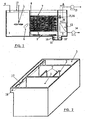
- Figures 1 and 2 represent the essential features of the system. It consists of three chambers: anoxic chamber (1); air-lift type aerobic chamber (2); and filtration chamber (3).
- the microbial sludge in suspension is maintained in the three chambers.
- Confined in the aerobic chamber (2) there is also a granular and coarse plastic support having a density of less than that of the water, on which support a biofilm with a high fraction of nitrifying microorganisms grows.
- the system incorporates in its filtration chamber (3) hollow fiber ultrafiltration membrane modules (12) which are used for separating the treated water from the biological sludge, recirculating the sludge from this chamber to the anoxic chamber (1).
- Figure 1 shows how the waste water is introduced into the anoxic chamber (1) through the conduit located in the upper part thereof (4), the influent mixing with the mixture liquor present in the chamber.
- the homogeneity of the mixture formed by microorganisms in suspension and waste water is ensured using a suitable mechanical stirring device (5), such as a flow booster or mechanical stirrer.
- the biological denitrification occurs in chamber (1), due to which part of the nitrogen anions present in the water are reduced to gaseous nitrogen by means of the biocatalyst present, furthermore carrying out the elimination of a high fraction of the organic pollutants in the denitrification process and the absorption of soluble organic compounds, such that it eliminates part of the organic matter from the water which otherwise could be assimilated by the biofilms present in the aerobic chamber (2).
- the conduit of figure 3 allows the passage of the mixture liquor from the anoxic chamber (1) to the aerobic chamber (2).
- This passage way is formed by one or more circular-section conduits (6) through which the mixture liquor coming from (1) to (2) circulates.
- the angled design of the conduit is proposed such that the re-mixing of the fluid between chambers is limited and the entrance of the support of the aerobic chamber (2) to the anoxic chamber (1), as well as the sludge deposit therein, is minimized or prevented.
- the inclination of the inclined span of the tube with regard to the horizontal span thereof will be comprised between 20° and 90°.
- the aerobic chamber is an air-lift type device in which two deflector plates or baffles dividing this chamber into three rectangular sections (figures 1 and 2) are assembled: a central section called a riser, which on its lower part is provided with diffusers through which air is distributed, and two sections on the sides called downcomers.
- a coarse granular plastic support is confined in this aerobic chamber (2), which has a density from 5% to 15% less than that of the water, the size of the support particles comprised between 1.5 and 5 mm and on which particles the biofilm grows.
- the introduction of the necessary airflow is carried out from the air supply conduit (8) towards a cluster of grid assembled diffusers (9) located in the lower part of the riser section.
- the airflow will be suitable so as to ensure the transfer of the oxygen necessary for producing the biochemical reactions occurring and so as to maintain the circulation of the plastic support and the mixture liquor in the aerobic chamber.
- the correct operation of the hybrid reactor requires that the plastic granular support used is confined in the aerobic chamber (2).
- a device is arranged to prevent outflows of the plastic granular support towards the filtration chamber (3), with which device the mixture liquor is separated from the plastic support (figures 1 and 4) in the lower end of the riser area (10) next to the filtration chamber (3).
- the separation device is formed by a rectangular section well (10) provided with a circular section tube (11) communicating the aerobic chamber with a second well (10') located in the membrane filtration chamber.
- the tube used is characterized by having the end placed in the well 10 closed and the other end open towards the well 10', and a rectangular section longitudinal groove facing downwards, through which the mixture liquor passes from 10 to 10', thus the mixture liquor flowing from the aerobic chamber (2) to the filtration chamber (3) is collected, thus preventing the suction and transport of plastic support particles towards (3).
- the bedplate of the wells (10 and 10') of the chambers (2) and (3) are built with a slope comprised between 20 and 45°, for the purpose of minimizing the sludge deposits in these areas (BB' section, figure 4).
- the treated waste water is separated (as a permeate) from the mixture liquor in chamber (3) using cassettes which are provided with the hollow fiber membrane filtration systems.
- the cassettes are submerged in the mixture liquor, such that the outer part of the filtration membranes are in contact with the sludge, whereas the inner part of the fibers is in contact with the filtered effluent which is evacuated, through a conduit connected to a centrifugal pump (13), figure 1. It is recommended to use hollow fiber membrane ultrafiltration or microfiltration modules manufactured in polysulfanes, polypropylene or any other suitable organic polymer.
- Said modules will be assembled in cassettes or rectangular structures, and with suitable membrane cleaning systems, by means of air current injection, back-washed with the permeate or any other system recommended for the application. It is recommended to use ZeeWeed® membrane filtration systems of the company Zenon Environmental Inc., or equivalent systems.
- the sludge surplus generated is purged in a controlled manner through a conduit which splits off from the filtration chamber (3) and is coupled to the pump (14), figure 1.
- a sludge recirculation device (figure 1 and figure 5) formed by a horizontal flow centrifugal impeller (15) which directs through the conduit (16) a current of mixture liquor from the filtration chamber (3) to a recirculation channel (18) located on a side of the system (figure 2 and figure 5).
- the sludge is recirculated through this channel, unloading the mixture liquor in the anoxic chamber (1) through a rectangular overflow (17).
- the size of the reactor depends on the flow rate of waste water to be treated as well as on the intrinsic features of the waste water itself (concentration of pollutants, temperature, presence of inhibiting or toxic substances for the biological processes) which will influence the pollutant- load rate which will be recommended for the design of the reactor.
- the organic load rate is comprised between 2.5 and 7 kg/m 3 ⁇ d of COD;
- the nitrification rate, in reference to the aerobic chamber is comprised between 0.5 and 1.5 kg/m 3 ⁇ d of N-NH 4 + ;
- the denitrification rate, in reference to the volume of the anoxic chamber (1) is comprised between 0.5 and 1.2 kg/m 3 ⁇ d of N-NO x - .
- the design of the reactor will be formed by three chambers, preferably having a rectangular section, or other different combined geometric forms (oval, circular, etc.).
- the ratio between the volumes of the three chambers, in reference to the total volume of the reactor, will be 45% for the anoxic chamber (1), 45-50% for the aerobic chamber (2), and 5-10% for the membrane filtration chamber (3).
- the hollow fiber membrane filtration modules will have the previously recommended features and specifications.
- the recommended modules have a capacity to filter, under stationary operation conditions, between 20 and 30 L of permeated effluent per square meter of membrane and operation time.
- a hybrid biological membrane reactor for treating waste waters from fish canning industries A hybrid biological membrane reactor for treating waste waters from fish canning industries .
- the recirculation ratio used would be 3.
- the concentration of oxygen dissolved in the aerobic chamber would be higher than 3 mg/L, whereas in the anoxic chamber the concentration of oxygen would be maintained below 0.3 mg/L.
- the ammonium load in the aerated section limits the volume of the system, and is established at 1.0 kg N-NH 4 + /m 3 ⁇ d.
- the organic matter load in the system would be 2.9 kg COD/m 3 ⁇ d.
- the total volume of the reactor would be 14 m 3 , and considering that the percentages of the total volume of the anoxic, aerobic chambers and of the membrane compartment are 45%, 45% and 10% of the total volume, 6.3 m 3 would correspond to the aerobic tank, 6.3 m 3 to the anoxic tank and the compartment of the membrane unit would have a volume of 1.4 m 3 .
- the system is capable of nitrifying 98% if the ammonium load applied to the system (0.98 kg N-NH 4 + / m 3 ⁇ d), the elimination of nitrogen reaches 86%, whereas the elimination of the total COD in the system (total volume) is 92% (2.7 kg COD/ m 3 ⁇ d).
Landscapes
- Life Sciences & Earth Sciences (AREA)
- Biodiversity & Conservation Biology (AREA)
- Microbiology (AREA)
- Hydrology & Water Resources (AREA)
- Engineering & Computer Science (AREA)
- Environmental & Geological Engineering (AREA)
- Water Supply & Treatment (AREA)
- Chemical & Material Sciences (AREA)
- Organic Chemistry (AREA)
- Separation Using Semi-Permeable Membranes (AREA)
- Biological Treatment Of Waste Water (AREA)
- Activated Sludge Processes (AREA)
Abstract
Description
- This invention refers to a hybrid biological membrane reactor for the treatment of industrial and urban waste water with organic and nitrogenous matter. It is constituted of three chambers: anoxic, aerobic and membrane filtration chambers. The proposed reactor is a compact system with which very low or negligible levels of solids in suspension in the purified effluent are obtained. ,
- Description of the state of the art of the main: A) Technologies in biological treatment and elimination processes of organic and nitrogenous pollutants; and B) Membrane bioreactor and hybrid reactor systems for waste water treatment.
- Biological treatment systems are widely used for eliminating organic pollutants composed of nitrogen and phosphorus, and are based on biological processes which use cultures of different species of microorganisms, mainly bacteria, fungi, algae, protozoa and metazoa.
- The elimination of organic and nitrogenous matter in biological treatment systems is carried out by means of two types of microorganisms: heterotrophic microorganisms and nitrifying bacteria. The heterotrophic microorganisms are characterized by using organic compounds in their growth, under both aerobic (using oxygen as an oxidizing agent) or anoxic (reducing nitrite or nitrate to gaseous nitrogen) conditions. The nitrifying bacteria oxidize ammonium to nitrite or nitrate, under aerobic conditions and are characterized by having a lower growth rate and lower cell production rate than the heterotrophic bacteria.
- The traditional processes are classified in: (A.1) biomass in suspension treatment systems, and (A.2) biofilm systems. The first systems are characterized in that the microorganisms grow forming flocculi which are placed in contact with the waste water; and the second systems are characterized in that the microorganisms grow on solid supports, forming microbial aggregates called biofilms (Metcalf & Eddy Inc. Ingenieria de Aguas Residuales, Ed. McGraw Hill, (1995); Henze et al. Wastewater treatment. Ed. Springer, (1997)).
- The hybrid treatment processes would be a third type of systems combining the presence of biomass in suspension and biofilm-forming biomass.
- A.1) The active sludge process developed in the United Kingdom in 1914 (Andern E. and Lockett W.T.J. Soc. Chem. Ind. 33, 523 (1914)) stands out in the biomass in suspension. systems. It is provided with a reactor where a microbial culture in suspension is maintained under aerobic conditions, and a settler for separating the treated waste water from the microbial sludge, recirculating it to the biological system. The active sludge process was initially designed for eliminating polluting organic matter, but different configurations of the process for eliminating nitrogen and phosphorus compounds from the waste water were subsequently developed. Configurations provided with one or multiple reactors are normally used, which are continuously or intermittingly maintained under anoxic or anaerobic conditions for the purpose of promoting the additional elimination of these nutrients. One of the important drawbacks of the system is that it operates with low biomass concentrations, limiting the pollutant conversion rate in the unit, so that relatively large units should therefore be built. In spite of this, it is the most used biological treatment process because it is heavy-duty and reliable.
- A.2) The following stand out in the immobilized microorganism biofilm systems:
1) trickling filters, 2) rotating biological contactors and 3) submerged biological filters.
- A.2.1) Trickling filters, used since the 19th century, consist of a column provided with a filler (of pebbles, stones, strips of wood, plastic support, etc.) which is held in place and on which a biofilm formed by microorganisms grows. In the column, open at its upper and lower ends, the waste water is distributed throughout the entire system, placing the waste water, biofilms and the air into contact. The main applications of the trickling filters are the elimination of organic matter and the biological nitrification treatment. Their use is not recommended when it is necessary to eliminate nitrogen from the waste water.
- A.2.2) Rotating biological contactors, known as biodisks, are formed by a high specific surface plastic disk supports on which a biofilm grows; the disks, coupled to a rotating shaft, are partially submerged in the waste water. The rotation of the disks allows the correct transfer of oxygen from the air to the biofilm and facilitates the contact of the biofilm with the pollutants present in the waste water. The biodisk process originated in the Technical University of Stuttgart (Germany) in 1955, and the first industrial scale plant was started up in the United States in 1969. The biodisks have the same drawback as the trickling filters, so that they are therefore rarely used if nitrogen is to be eliminated.
- A.2.3) The operating principle of the submerged biological filters is similar to that of the trickling filters, although in these systems, the column containing the support is completely inundated with waste water. The air supply, if it were necessary, is ensured by means of the injection of air and there are also units operating under anoxic conditions for denitrification. The supports for the growth of the biofilms are organic materials such as polyethylene, polystyrene, polyurethane, expanded clay granular particles, pozzolan particles, sand, or other materials with sizes generally comprised between 1 and 5 mm. The first industrial scale biofilters were developed in the 1970s in France using expanded clays as a support (Lazarova and Manen, Biofilms II: Process Analysis and Applications, Editor James E. Bryers, (2000)). Some of these systems used granular plastic supports having a density which is slightly less than that of the water (patents FR2707183 and WO9713727), on which a biofilm grows, which permits fluidizing said supports in a simple manner, introducing a gas flow into the system. The submerged biofilters are very compact units used for different purposes: anaerobic elimination, denitrification and/or aerobic oxidation of organic matter as well as nitrification of ammonium in waste waters, and they have relatively high pollutant elimination rates. One of the most general drawbacks for their application is derived from the great technical complexity.
-
- The hybrid systems are characterized by combining the presence of biomass in suspension with biomass immobilized in a support in the same system, which allows maintaining higher biocatalyst concentrations than those which are used in biomass in suspension reactors, this particularity constitutes an advantage, since the waste water can be purified in hybrid equipment which are more compact than the classic active sludge systems. Furthermore, the possibility exists of transforming the already built active sludge plants into hybrid system plants by carrying out small modifications in the civil work and adding a suitable support so as to increase the treatment capacity of the plant.
- The hybrid reactors are becoming more and more important in the purification of waste waters with organic and nitrogenous matter, since they combine the heavy-duty nature of the active sludge systems with the greater purification capacity of the biofilm systems.
- Examples of hybrid systems are US patent 5,061,368 and the literature (Andreottola et al.; Münch et al.; Ødegaard et al.; Wat. Sci. Technol. v41, number 4-5 (1999)), which use plastic supports like those disclosed in US patents US 5,458,779, US 5,543,039 and US 6,126,829 to improve the yield of different biological reactors in which biomass grows in suspension as well as in biofilms.
- US patent 5,061,368 uses a hybrid system which alternates anaerobic and anoxic chambers, maintaining biomass in suspension in the entire system and biomass immobilized in gel cubes retained in nitrifying aerobic chambers. A drawback of this system is that it artificially immobilizes nitrifying microorganisms in polyethylene glycol gel cubes which must be periodically replaced so as to substitute those gel particles which break or wear, it is therefore necessary to manufacture new gel cubes, not only during the start-up stage, but also during the continuous operation of the system. Furthermore, high load rates cannot be applied since they may cause the gel cubes to break due to the increased growth rate of the immobilized microorganisms.
- Another drawback of the systems disclosed in the publications mentioned above are those which can arise from the application of high organic load rates, as well as from the physicochemical features of the waste water, which can negatively affect the settleability properties of the sludge which is generated in the biological systems and can therefore negatively affect the separation, by means of settlers, of solids from the treated water. Said hybrid systems use settlers due to which, for certain applications and under certain conditions, their efficiency can be affected by an incorrect separation of the solids from the treated water.
- The first reference of the use of membrane systems dates back to 1969. An ultrafiltration membrane was used for separating the treated waste water from the biomass in an active sludge system. The combination of the two technologies has lead to the development of three groups of biological membrane processes; i) liquid-solid separation by means of membranes for retaining the biomass in biological reactors; ii) the use of membranes permeable to a gaseous compound for the transfer of oxygen without bubbling in reactors; iii) an extractive membrane process applied for eliminating degradable organic compounds in problematic industrial waste waters (Brindle K. and Stephenson T., Biotechnol. Bioeng. 49, 601-610 (1996)). It is worth pointing out that the hybrid membrane system proposed in our invention is an additional novel application of the first group (i), where membrane filtration systems are used for separating the waste water from the microorganisms.
- The majority of current biological treatment systems using membranes are modifications of the active sludge process, where the secondary settler, used in traditional processes, has been substituted with membrane filtration units for separating the microorganisms in suspension from the water treated in biomass in suspension reactors. The membranes used for this purpose are microfiltration or ultrafiltration membranes manufactured with organic or inorganic materials arranged on hollow fiber, plate or tubular, modules which can be arranged inside or outside of the biological reactor (Günder B. and Krauth K., Wat. Sci. Technol., vol 38, pp 382-393 (1998); Buisson H. et al. Wat. Sci. Technol. 37(9), pp 89-95 (1998); Günder B. and Krauth K., Wat. Sci. Technol., vol 40, pp 311-320 (1999), Ghyoot W. and Verstraete W., Wat. Res., 34, pp 205-215, (2000)). There are also different patents based on the use of different membrane filtration modules which can or could be used in the separation of the waste water treated in biomass in suspension bioreactors (US patents 5,558,774 and 6,303,035).
- The present invention implies improvements in the waste water biological treatment systems, in general, and hybrid reactors in particular. One of the main - features of the hybrid reactor proposed-is that of confining particles of a plastic granular support in the aerobic chamber, having a density slightly less than that of the water. This support neither breaks nor deteriorates by use in the system; furthermore, if will not break due to growth of the biomass therein (as can occur in systems using microorganisms immobilized in the polymeric gels), since the growth is limited to the surface of the plastic support. Thus, the need to have an available stock of gel particles with microorganisms is also saved.
- Another advantage is the use of a hollow fiber membrane filtration system. As was mentioned, in hybrid systems using settlers for separating the purified water from the biological sludge, the efficiency of the separation depends on the settleability properties of the sludge, and it can worsen if high polluting loads are applied in the system. The proposed membrane filtration system makes the process of separating the treated waste water and the sludge with settleability properties independent, therefore higher load rates can be applied without the risk of undergoing operation problems in the system. Furthermore, the possible washing of the sludge of the biological reactor is prevented.
- The assembly of membrane filtration units in the hybrid reactor makes it possible to obtain an effluent with low levels of solids in suspension, which would comply with the most demanding dumping requirements of this pollutant, significantly decreases the dumping of microorganisms with the effluent (including pathogens and other health vectors); furthermore, it is suitable for dumping close to marine culture areas or fish hatcheries and collection areas for collecting waters used for irrigation or for producing drinking water.
- In the proposed biological reactor, the plastic granular support with the biofilms are confined in the aerobic chamber, using separation devices which allow the free passage of the mixture liquor, with the microorganisms in suspension between the three chambers which the unit consists of.
- With this proposal, it is possible to operate the system with a sludge in suspension containing a high fraction of heterotrophic microorganisms needed for denitrifying in the anoxic chamber and eliminating the soluble organic matter residue which could reach the aerobic chamber; thus, the growth of heterotrophic bacteria in the biofilm is limited, the growth of nitrifying bacteria in the biofilm is promoted and because of this, it prevents the nitrifying capacity of the biofilm growing on the plastic support from being inhibited or reduced. All this allows applying and operating with relatively high organic (kg COD/m3·d) and nitrogenous (kg N-NH4 +/m3·d) loads and which are higher than that of the aforementioned systems, without the system undergoing, as a result, decreases of purification efficiency or problems due to the breaking or clogging of the support due to the growth of the biomass.
- Figures 1-5 show the hybrid biological membrane reactor.
- Figure 1 shows a scheme of the reactor constituted of three chambers: anoxic chamber (1), aerobic chamber (2) and filtration chamber (3).
- Figure 2 shows a three-dimensional perspective view of the reactor, showing the three chambers, the two deflector plates (7) of the aerobic chamber, waste water recirculation channel (18) and overflow (17). The civil work has been pointed out, omitting auxiliary equipment.
- Figure 3 shows a shape and arrangement of the mixture liquor passage conduit (6) from the anoxic chamber (1) to the aerobic chamber (2).
- Figure 4 shows collection wells (10 and 10') of the mixture liquor from the aerobic chamber (2) to the filtration chamber (3). The conduit (11) is used for carrying the waste water between the chambers.
- Figure 5 shows an AA' section (in figure 1) view showing a impeller device for driving the mixture liquor from the filtration chamber to the anoxic chamber, showing the centrifugal stirrer (15), the conduit (16) and the recirculation channel (18).
-
- Figures 1 and 2 represent the essential features of the system. It consists of three chambers: anoxic chamber (1); air-lift type aerobic chamber (2); and filtration chamber (3). The microbial sludge in suspension is maintained in the three chambers. Confined in the aerobic chamber (2) there is also a granular and coarse plastic support having a density of less than that of the water, on which support a biofilm with a high fraction of nitrifying microorganisms grows. The system incorporates in its filtration chamber (3) hollow fiber ultrafiltration membrane modules (12) which are used for separating the treated water from the biological sludge, recirculating the sludge from this chamber to the anoxic chamber (1).
- Figure 1 shows how the waste water is introduced into the anoxic chamber (1) through the conduit located in the upper part thereof (4), the influent mixing with the mixture liquor present in the chamber. The homogeneity of the mixture formed by microorganisms in suspension and waste water is ensured using a suitable mechanical stirring device (5), such as a flow booster or mechanical stirrer.
- The biological denitrification occurs in chamber (1), due to which part of the nitrogen anions present in the water are reduced to gaseous nitrogen by means of the biocatalyst present, furthermore carrying out the elimination of a high fraction of the organic pollutants in the denitrification process and the absorption of soluble organic compounds, such that it eliminates part of the organic matter from the water which otherwise could be assimilated by the biofilms present in the aerobic chamber (2).
- The conduit of figure 3 allows the passage of the mixture liquor from the anoxic chamber (1) to the aerobic chamber (2). This passage way is formed by one or more circular-section conduits (6) through which the mixture liquor coming from (1) to (2) circulates. The angled design of the conduit is proposed such that the re-mixing of the fluid between chambers is limited and the entrance of the support of the aerobic chamber (2) to the anoxic chamber (1), as well as the sludge deposit therein, is minimized or prevented. The inclination of the inclined span of the tube with regard to the horizontal span thereof will be comprised between 20° and 90°.
- The aerobic chamber is an air-lift type device in which two deflector plates or baffles dividing this chamber into three rectangular sections (figures 1 and 2) are assembled: a central section called a riser, which on its lower part is provided with diffusers through which air is distributed, and two sections on the sides called downcomers. A coarse granular plastic support is confined in this aerobic chamber (2), which has a density from 5% to 15% less than that of the water, the size of the support particles comprised between 1.5 and 5 mm and on which particles the biofilm grows. It is recommended to use a coarse high density polyethylene support with the previously disclosed features, or like those disclosed in patents FR2707183 and WO9713727, which use a granular plastic support for waste water treatment in biofilm biological systems, unlike the hybrid biological membrane reactor proposed in our invention. The support volume fraction in this chamber will be comprised between 15 and 25% v/v, according to the application.
- In the aerobic chamber, the introduction of the necessary airflow is carried out from the air supply conduit (8) towards a cluster of grid assembled diffusers (9) located in the lower part of the riser section. The airflow will be suitable so as to ensure the transfer of the oxygen necessary for producing the biochemical reactions occurring and so as to maintain the circulation of the plastic support and the mixture liquor in the aerobic chamber.
- The correct operation of the hybrid reactor requires that the plastic granular support used is confined in the aerobic chamber (2). A device is arranged to prevent outflows of the plastic granular support towards the filtration chamber (3), with which device the mixture liquor is separated from the plastic support (figures 1 and 4) in the lower end of the riser area (10) next to the filtration chamber (3). The separation device is formed by a rectangular section well (10) provided with a circular section tube (11) communicating the aerobic chamber with a second well (10') located in the membrane filtration chamber. The tube used is characterized by having the end placed in the well 10 closed and the other end open towards the well 10', and a rectangular section longitudinal groove facing downwards, through which the mixture liquor passes from 10 to 10', thus the mixture liquor flowing from the aerobic chamber (2) to the filtration chamber (3) is collected, thus preventing the suction and transport of plastic support particles towards (3). The bedplate of the wells (10 and 10') of the chambers (2) and (3) are built with a slope comprised between 20 and 45°, for the purpose of minimizing the sludge deposits in these areas (BB' section, figure 4).
- The treated waste water is separated (as a permeate) from the mixture liquor in chamber (3) using cassettes which are provided with the hollow fiber membrane filtration systems. The cassettes are submerged in the mixture liquor, such that the outer part of the filtration membranes are in contact with the sludge, whereas the inner part of the fibers is in contact with the filtered effluent which is evacuated, through a conduit connected to a centrifugal pump (13), figure 1. It is recommended to use hollow fiber membrane ultrafiltration or microfiltration modules manufactured in polysulfanes, polypropylene or any other suitable organic polymer. Said modules will be assembled in cassettes or rectangular structures, and with suitable membrane cleaning systems, by means of air current injection, back-washed with the permeate or any other system recommended for the application. It is recommended to use ZeeWeed® membrane filtration systems of the company Zenon Environmental Inc., or equivalent systems.
- In the filtration chamber (3) the sludge surplus generated is purged in a controlled manner through a conduit which splits off from the filtration chamber (3) and is coupled to the pump (14), figure 1.
- For recirculating the sludge retained in the filtration chamber (3) towards the anoxic chamber (1), it,will be suitable to use a sludge recirculation device (figure 1 and figure 5) formed by a horizontal flow centrifugal impeller (15) which directs through the conduit (16) a current of mixture liquor from the filtration chamber (3) to a recirculation channel (18) located on a side of the system (figure 2 and figure 5). The sludge is recirculated through this channel, unloading the mixture liquor in the anoxic chamber (1) through a rectangular overflow (17).
- According to the present invention, the size of the reactor depends on the flow rate of waste water to be treated as well as on the intrinsic features of the waste water itself (concentration of pollutants, temperature, presence of inhibiting or toxic substances for the biological processes) which will influence the pollutant- load rate which will be recommended for the design of the reactor.
- For the case of urban or industrial waste waters with easily biodegradable organic components, the organic load rate is comprised between 2.5 and 7 kg/m3·d of COD; the nitrification rate, in reference to the aerobic chamber, is comprised between 0.5 and 1.5 kg/m3·d of N-NH4 +; and the denitrification rate, in reference to the volume of the anoxic chamber (1), is comprised between 0.5 and 1.2 kg/m3·d of N-NOx -.
- The design of the reactor will be formed by three chambers, preferably having a rectangular section, or other different combined geometric forms (oval, circular, etc.). The ratio between the volumes of the three chambers, in reference to the total volume of the reactor, will be 45% for the anoxic chamber (1), 45-50% for the aerobic chamber (2), and 5-10% for the membrane filtration chamber (3).
- The hollow fiber membrane filtration modules will have the previously recommended features and specifications.
- To calculate the surface of the membrane module that is needed, it is necessary to contact the supplier or manufacturer of said module. As a guideline, it is worth pointing out that the recommended modules have a capacity to filter, under stationary operation conditions, between 20 and 30 L of permeated effluent per square meter of membrane and operation time.
- Affluent waste water flow rate 21 m3/h; total COD concentration measured at the system inlet 1900 mg/L, ammonium concentration 300 mg N-NH4 +/L.
- The recirculation ratio used would be 3. The concentration of oxygen dissolved in the aerobic chamber would be higher than 3 mg/L, whereas in the anoxic chamber the concentration of oxygen would be maintained below 0.3 mg/L. The ammonium load in the aerated section limits the volume of the system, and is established at 1.0 kg N-NH4 +/m3·d. The organic matter load in the system would be 2.9 kg COD/m3·d. The total volume of the reactor would be 14 m3, and considering that the percentages of the total volume of the anoxic, aerobic chambers and of the membrane compartment are 45%, 45% and 10% of the total volume, 6.3 m3 would correspond to the aerobic tank, 6.3 m3 to the anoxic tank and the compartment of the membrane unit would have a volume of 1.4 m3. A volume of 1.26 m3 (20% v/v) of plastic granular support, having the previously indicated features, is needed to promote the growth of nitrifying biofilms in the aerobic chamber.
- The system is capable of nitrifying 98% if the ammonium load applied to the system (0.98 kg N-NH4 +/ m3·d), the elimination of nitrogen reaches 86%, whereas the elimination of the total COD in the system (total volume) is 92% (2.7 kg COD/ m3·d).
Claims (8)
- A hybrid biological membrane reactor for industrial and urban waste water treatment, characterized by being composed of three chambers: anoxic chamber (1), aerobic chamber (2) and membrane filtration chamber (3); the chambers have a rectangular section or one of any other geometric shape. The reactor is of application in organic and nitrogenous matter purification and elimination of solids in suspension.
- A reactor according to claim 1, characterized in that the anoxic chamber (1) is provided with one or several mechanical stirrers, an overflow with a rectangular section on one of its sides. Influent waste water is unloaded on the chamber through a conduit located on the upper part of the chamber. In the anoxic chamber, the influent waste water is placed in contact with the mixture liquor and a sludge current recirculated from the membrane filtration chamber (3), nitrate and a fraction of the organic matter present being eliminated. The homogeneity of the mixture liquor will be ensured and the deposit of sludges on the bottom will be prevented with the use of the suitable mechanical stirrers.
- A reactor according to claims 1 and 2, characterized by angular conduit(s) with circular section communicating the anoxic chamber (1) with the aerobic chamber (2). The conduit has an angled tube shape with two spans: a horizontal one and another one with an inclination comprised between 20 and 90° with regard to the first span.
- A reactor according to claim 1, characterized in that the airlift-type aerobic chamber (2) will be provided with a plastic granular support for the growth of biofilms. The chamber is provided with two deflector plates or baffles, which divide the chamber into three sections, the central aerated section and the other two non-aerated side sections, which are communicated with each other through the lower as well as the upper part of the chamber. A diffuser grid will be arranged on the lower part of the aerated section. An air current is supplied in the aerobic chamber through the diffuser grid in order to homogenize the mixture liquor and the granular plastic support particles and in order to transfer the oxygen which is necessary in the biochemical reactions occurring, organic matter oxidation and biological nitrification reaction. The air current induces the circulation of the support and the mixture liquid from the central aerated section, upwardly, and the two side sections, downwardly.
- A reactor according to claims 1 and 4, characterized by a coarse granular support of high density polyethylene plastic or plastic material with equivalent features, with a density from 5 to 15% less than that of the water, a size comprised between 1.5 and 5 mm. The volume of the support, located in the aerobic chamber, will be comprised between 15 and 25% v/v, with reference to the volume of the aerobic chamber, according to the application. A biofilm with a high nitrifying activity barely varying with the organic load and operation conditions, grows on said support.
- A reactor according to claims 1, 4 and 5, characterized by a separation device between the mixture liquor and the granular plastic support: the device is located under the diffuser grid of the aerobic chamber, and it is next to the filtration chamber. On one of its sides, the device is provided with a well with a rectangular section, and on the other side, it has a slope of the bedplate comprised between 20 and 45°. The device is provided with a tube communicating the well of the aerobic chamber with another similar well located in the filtration chamber (3). The tube has one end closed (in the aerobic chamber) and the other end open (towards the filtration chamber) and has an open longitudinal groove facing downward in the well of the aerobic chamber.
- A reactor according to claim 1, characterized in that the filtration chamber (3) is provided with hollow fiber membrane ultrafiltration or microfiltration modules, manufactured in polysulfones, polypropylene or any other suitable polymer. Said modules will be assembled in cassettes or rectangular structures provided with suitable membrane cleaning systems, by means of air current, back-washing with permeate or any other system recommended by the manufacturer of the membrane filtration modules, and which is compatible with the application. The purified waste water is filtered with the aid of one or more centrifugal pumps connected to the membrane filtration modules. It is recommended to use ZeeWeed® membrane filtration modules of the company Zenon Environmental Inc., or equivalent modules. The filtration chamber will be provided with a sludge purge line, which consists of a conduit connected to a pump, through which pump the generated sludge is periodically purged. The filtration chamber will be provided with a horizontal flow impeller and a conduit located on a side of the chamber with one end facing the horizontal flow impeller.
- A reactor according to claims 1, 2 and 7, characterized by a device for recirculating sludge from the membrane filtration chamber (3) towards the anoxic chamber (1), constituted of a horizontal flow impeller facing one end of a conduit located on one side of the anoxic chamber, which connects the latter to a rectangular channel assembled on one of the upper sides of the reactor. The rectangular channel extends from the filtration chamber to the anoxic chamber and is provided with an overflow next to the anoxic chamber. The mixture liquor or sludge retained in the filtration chamber is recirculated, using the horizontal flow impeller which leads the sludge through the conduit to the recirculation channel. The mixture liquor returns to the anoxic chamber through the overflow located on the recirculation channel.
Applications Claiming Priority (3)
| Application Number | Priority Date | Filing Date | Title |
|---|---|---|---|
| ES200200244A ES2190895B2 (en) | 2002-02-01 | 2002-02-01 | HYBRID BIOLOGICAL REACTOR OF MEMBRANES FOR TREATMENT OF INDUSTRIAL AND URBAN RESIDUAL WATERS. |
| ES200200244 | 2002-02-01 | ||
| PCT/ES2003/000057 WO2003064335A1 (en) | 2002-02-01 | 2003-01-31 | Hybrid biological membrane reactor for the treatment of urban and industrial waste water |
Publications (2)
| Publication Number | Publication Date |
|---|---|
| EP1484287A1 true EP1484287A1 (en) | 2004-12-08 |
| EP1484287B1 EP1484287B1 (en) | 2006-04-05 |
Family
ID=27838334
Family Applications (1)
| Application Number | Title | Priority Date | Filing Date |
|---|---|---|---|
| EP03734736A Expired - Lifetime EP1484287B1 (en) | 2002-02-01 | 2003-01-31 | Hybrid biological membrane reactor for the treatment of urban and industrial waste water |
Country Status (5)
| Country | Link |
|---|---|
| EP (1) | EP1484287B1 (en) |
| AT (1) | ATE322467T1 (en) |
| DE (1) | DE60304456T2 (en) |
| ES (1) | ES2190895B2 (en) |
| WO (1) | WO2003064335A1 (en) |
Cited By (12)
| Publication number | Priority date | Publication date | Assignee | Title |
|---|---|---|---|---|
| WO2007093440A1 (en) * | 2006-02-17 | 2007-08-23 | Itn Nanovation Ag | Purification method for effluent |
| US7288197B2 (en) | 2004-12-22 | 2007-10-30 | Industrial Technology Research Institute | Biological membrane filtration system for water treatment and a water treatment process |
| KR100853077B1 (en) | 2008-04-08 | 2008-08-19 | 효성에바라엔지니어링 주식회사 | Immersion type PET membrane bioreactor and high sewage treatment method |
| WO2008155407A1 (en) * | 2007-06-21 | 2008-12-24 | Biokube International A/S | A unit, a plant and a method for treatment of polluted water |
| RU2426696C2 (en) * | 2009-02-02 | 2011-08-20 | Андрей Олегович Бобылёв | Method of effluents treatment and device to this end |
| CN101734793B (en) * | 2008-11-27 | 2012-10-10 | 陈光浩 | Sewage treatment system and sewage treatment method |
| CN104407100A (en) * | 2014-10-31 | 2015-03-11 | 北京城市排水集团有限责任公司 | Intelligent analysis system of sludge nitrification activity, and analysis method thereof |
| CN105087451A (en) * | 2015-10-08 | 2015-11-25 | 南京大学 | Preparation method for denitrified microbial agent |
| WO2016048151A1 (en) * | 2014-09-26 | 2016-03-31 | Van Der Ende Pompen B.V. | Method and system for treating a fluid flow |
| EP2952483A4 (en) * | 2013-02-01 | 2016-08-03 | Univ Santiago Compostela | INTEGRATED SYSTEM COMPRISING A METHANOGENIC ANAEROBIC REACTOR AND A MEMBRANE BIOREACTOR FOR THE REMOVAL OF ORGANIC MATTER AND NITROGEN FROM WASTE WATER |
| RU2608527C2 (en) * | 2015-06-17 | 2017-01-19 | Публичное акционерное общество "Газпром" | Biocomposite for purification of waste water from nitrite-, nitrate-, phosphate ions |
| WO2022041689A1 (en) * | 2020-08-25 | 2022-03-03 | 南京汉尔斯生物科技有限公司 | Energy-saving anti-blocking drain pool and use method thereof |
Families Citing this family (11)
| Publication number | Priority date | Publication date | Assignee | Title |
|---|---|---|---|---|
| WO2005107929A2 (en) | 2004-04-22 | 2005-11-17 | Siemens Water Technologies Corp. | Filtration apparatus comprising a membrane bioreactor and a treatment vessel for digesting organic materials |
| US7147777B1 (en) * | 2005-05-09 | 2006-12-12 | Eimco Water Technologies Llc | Wastewater treatment system with membrane separators and provision for storm flow conditions |
| CN100357197C (en) * | 2006-01-12 | 2007-12-26 | 上海大学 | Integral membrane biological reaction device for water treatment |
| CN101618925B (en) * | 2009-07-27 | 2011-08-03 | 北京汉青天朗水处理科技有限公司 | Sewage treatment device |
| CN101973681B (en) * | 2010-11-12 | 2011-12-07 | 昆明水啸科技有限公司 | Sewage treatment technology with sequencing mud membrane symbiosis method |
| CN102120680B (en) * | 2011-04-15 | 2012-10-03 | 龙江环保集团股份有限公司 | Anoxic/oxic-membrane bioreactor water treatment device and sewage treatment method thereof |
| CN103341285B (en) * | 2013-07-16 | 2015-04-15 | 哈尔滨工业大学 | Advection sedimentation/immersion type ultrafiltration integrated water treatment device |
| CN107619105A (en) * | 2016-07-15 | 2018-01-23 | 深圳市深水生态环境技术有限公司 | River channel ecology processing system and the smelly water body treating biofilm reactor of urban black |
| SK7919Y1 (en) | 2016-11-30 | 2017-11-03 | Pavol Pijak | Biological wastewater treatment plant |
| EP4289796A4 (en) | 2021-02-02 | 2024-08-07 | Biologia Y Filtración, S.L. | Industrial and municipal wastewater treatment plant |
| CN118026408B (en) * | 2024-04-11 | 2024-06-14 | 四川发展环境科学技术研究院有限公司 | System and method for removing nitrogen and phosphorus in sewage by iron ion driven denitrification-anaerobic ammoxidation |
Family Cites Families (6)
| Publication number | Priority date | Publication date | Assignee | Title |
|---|---|---|---|---|
| GB1601036A (en) * | 1977-11-11 | 1981-10-21 | Thetford Corp | Closed loop waste treatment and water recycying toilet system |
| US4122013A (en) * | 1977-11-15 | 1978-10-24 | Greenleaf Jr John W | Sewage treatment system |
| US4904387A (en) * | 1988-06-17 | 1990-02-27 | Thetford Corporation | Waste treatment and water recycling toilet system |
| JP2776983B2 (en) * | 1992-08-10 | 1998-07-16 | プロテック パルトナー フューア ウムヴェルト テヒニーク ゲゼルシャフト ミット ベシュレンクテル ハフツング | Method and apparatus for biologically treating organic matter-containing wastewater and organic waste |
| WO2001005715A1 (en) * | 1999-07-20 | 2001-01-25 | Zenon Environmental Inc. | Biological process for removing phosphorus involving a membrane filter |
| US6413427B2 (en) * | 2000-03-29 | 2002-07-02 | Ecokasa Incorporated | Nitrogen reduction wastewater treatment system |
-
2002
- 2002-02-01 ES ES200200244A patent/ES2190895B2/en not_active Expired - Fee Related
-
2003
- 2003-01-31 WO PCT/ES2003/000057 patent/WO2003064335A1/en not_active Ceased
- 2003-01-31 DE DE2003604456 patent/DE60304456T2/en not_active Expired - Lifetime
- 2003-01-31 EP EP03734736A patent/EP1484287B1/en not_active Expired - Lifetime
- 2003-01-31 AT AT03734736T patent/ATE322467T1/en not_active IP Right Cessation
Non-Patent Citations (1)
| Title |
|---|
| See references of WO03064335A1 * |
Cited By (15)
| Publication number | Priority date | Publication date | Assignee | Title |
|---|---|---|---|---|
| US7288197B2 (en) | 2004-12-22 | 2007-10-30 | Industrial Technology Research Institute | Biological membrane filtration system for water treatment and a water treatment process |
| WO2007093440A1 (en) * | 2006-02-17 | 2007-08-23 | Itn Nanovation Ag | Purification method for effluent |
| US8070948B2 (en) | 2006-02-17 | 2011-12-06 | Itn Nanovation Ag | Method of purifying wastewater and sewage treatment plant |
| WO2008155407A1 (en) * | 2007-06-21 | 2008-12-24 | Biokube International A/S | A unit, a plant and a method for treatment of polluted water |
| US8419942B2 (en) | 2007-06-21 | 2013-04-16 | Biokube International A/S | Unit, a plant and a method for treatment of polluted water |
| KR100853077B1 (en) | 2008-04-08 | 2008-08-19 | 효성에바라엔지니어링 주식회사 | Immersion type PET membrane bioreactor and high sewage treatment method |
| CN101734793B (en) * | 2008-11-27 | 2012-10-10 | 陈光浩 | Sewage treatment system and sewage treatment method |
| RU2426696C2 (en) * | 2009-02-02 | 2011-08-20 | Андрей Олегович Бобылёв | Method of effluents treatment and device to this end |
| EP2952483A4 (en) * | 2013-02-01 | 2016-08-03 | Univ Santiago Compostela | INTEGRATED SYSTEM COMPRISING A METHANOGENIC ANAEROBIC REACTOR AND A MEMBRANE BIOREACTOR FOR THE REMOVAL OF ORGANIC MATTER AND NITROGEN FROM WASTE WATER |
| WO2016048151A1 (en) * | 2014-09-26 | 2016-03-31 | Van Der Ende Pompen B.V. | Method and system for treating a fluid flow |
| CN104407100A (en) * | 2014-10-31 | 2015-03-11 | 北京城市排水集团有限责任公司 | Intelligent analysis system of sludge nitrification activity, and analysis method thereof |
| RU2608527C2 (en) * | 2015-06-17 | 2017-01-19 | Публичное акционерное общество "Газпром" | Biocomposite for purification of waste water from nitrite-, nitrate-, phosphate ions |
| CN105087451A (en) * | 2015-10-08 | 2015-11-25 | 南京大学 | Preparation method for denitrified microbial agent |
| CN105087451B (en) * | 2015-10-08 | 2018-07-10 | 南京大学 | A kind of preparation method of denitrification microorganism microbial inoculum |
| WO2022041689A1 (en) * | 2020-08-25 | 2022-03-03 | 南京汉尔斯生物科技有限公司 | Energy-saving anti-blocking drain pool and use method thereof |
Also Published As
| Publication number | Publication date |
|---|---|
| DE60304456D1 (en) | 2006-05-18 |
| ES2190895B2 (en) | 2004-05-16 |
| WO2003064335A1 (en) | 2003-08-07 |
| ATE322467T1 (en) | 2006-04-15 |
| EP1484287B1 (en) | 2006-04-05 |
| ES2190895A1 (en) | 2003-08-16 |
| DE60304456T2 (en) | 2007-04-19 |
Similar Documents
| Publication | Publication Date | Title |
|---|---|---|
| EP1484287B1 (en) | Hybrid biological membrane reactor for the treatment of urban and industrial waste water | |
| Leyva-Díaz et al. | Comparative kinetic study between moving bed biofilm reactor-membrane bioreactor and membrane bioreactor systems and their influence on organic matter and nutrients removal | |
| US6926830B2 (en) | Combined activated sludge-biofilm sequencing batch reactor and process | |
| US4279753A (en) | Wastewater treatment system including multiple stages of alternate aerobic-anerobic bioreactors in series | |
| US5211847A (en) | Denitrification methods | |
| US6423229B1 (en) | Bioreactor systems for biological nutrient removal | |
| US12221369B2 (en) | Method and apparatus for nutrient removal using anoxic biofilms | |
| CN104671616B (en) | A kind of cities and towns and the advanced sewage treatment system of industrial park | |
| CA2052152C (en) | Denitrification systems and methods | |
| Sørensen et al. | Biofilm reactors | |
| KR101079701B1 (en) | Enrichment of anaerobic ammonium oxidizers in a membrane bioreactor | |
| CN102951731A (en) | Airlift oxidation ditch type membrane bioreactor | |
| US11760670B2 (en) | Fixed biofilm anaerobic-aerobic combined reactor for treating wastewater | |
| CN101734793B (en) | Sewage treatment system and sewage treatment method | |
| KR20140132258A (en) | Biological Advanced Wastewater Treatment Technology | |
| CN213171940U (en) | High-efficient sewage treatment system of modularization integrated form | |
| KR100417488B1 (en) | Anaerobic Waste-water Treatment System | |
| CN211921025U (en) | Sludge-membrane symbiotic MBR sewage treatment container | |
| CN114702127A (en) | Circulating biological reaction membrane separation sewage treatment system capable of realizing multipoint water feeding | |
| CN202080953U (en) | Sludge non-return device with SND denitriding function | |
| Rodríguez-Hernández et al. | Evaluation of a hybrid vertical membrane bioreactor (HVMBR) for wastewater treatment | |
| WO2008051546A2 (en) | Infiltration/inflow control for membrane bioreactor | |
| CN214571379U (en) | Fuel cell production wastewater treatment system | |
| KR19990083645A (en) | Organic material and nitrogen, phosphate removal method using intermitted aeration process and plate type microfiltration membrane | |
| CN205313183U (en) | Ecological processing system of vertical current sewage |
Legal Events
| Date | Code | Title | Description |
|---|---|---|---|
| PUAI | Public reference made under article 153(3) epc to a published international application that has entered the european phase |
Free format text: ORIGINAL CODE: 0009012 |
|
| 17P | Request for examination filed |
Effective date: 20040811 |
|
| AK | Designated contracting states |
Kind code of ref document: A1 Designated state(s): AT BE BG CH CY CZ DE DK EE ES FI FR GB GR HU IE IT LI LU MC NL PT SE SI SK TR |
|
| AX | Request for extension of the european patent |
Extension state: AL LT LV MK RO |
|
| 17Q | First examination report despatched |
Effective date: 20050523 |
|
| GRAP | Despatch of communication of intention to grant a patent |
Free format text: ORIGINAL CODE: EPIDOSNIGR1 |
|
| GRAS | Grant fee paid |
Free format text: ORIGINAL CODE: EPIDOSNIGR3 |
|
| GRAA | (expected) grant |
Free format text: ORIGINAL CODE: 0009210 |
|
| AK | Designated contracting states |
Kind code of ref document: B1 Designated state(s): AT BE BG CH CY CZ DE DK EE ES FI FR GB GR HU IE IT LI LU MC NL PT SE SI SK TR |
|
| PG25 | Lapsed in a contracting state [announced via postgrant information from national office to epo] |
Ref country code: IT Free format text: LAPSE BECAUSE OF FAILURE TO SUBMIT A TRANSLATION OF THE DESCRIPTION OR TO PAY THE FEE WITHIN THE PRESCRIBED TIME-LIMIT;WARNING: LAPSES OF ITALIAN PATENTS WITH EFFECTIVE DATE BEFORE 2007 MAY HAVE OCCURRED AT ANY TIME BEFORE 2007. THE CORRECT EFFECTIVE DATE MAY BE DIFFERENT FROM THE ONE RECORDED. Effective date: 20060405 Ref country code: CH Free format text: LAPSE BECAUSE OF FAILURE TO SUBMIT A TRANSLATION OF THE DESCRIPTION OR TO PAY THE FEE WITHIN THE PRESCRIBED TIME-LIMIT Effective date: 20060405 Ref country code: AT Free format text: LAPSE BECAUSE OF FAILURE TO SUBMIT A TRANSLATION OF THE DESCRIPTION OR TO PAY THE FEE WITHIN THE PRESCRIBED TIME-LIMIT Effective date: 20060405 Ref country code: FI Free format text: LAPSE BECAUSE OF FAILURE TO SUBMIT A TRANSLATION OF THE DESCRIPTION OR TO PAY THE FEE WITHIN THE PRESCRIBED TIME-LIMIT Effective date: 20060405 Ref country code: SK Free format text: LAPSE BECAUSE OF FAILURE TO SUBMIT A TRANSLATION OF THE DESCRIPTION OR TO PAY THE FEE WITHIN THE PRESCRIBED TIME-LIMIT Effective date: 20060405 Ref country code: CZ Free format text: LAPSE BECAUSE OF FAILURE TO SUBMIT A TRANSLATION OF THE DESCRIPTION OR TO PAY THE FEE WITHIN THE PRESCRIBED TIME-LIMIT Effective date: 20060405 Ref country code: SI Free format text: LAPSE BECAUSE OF FAILURE TO SUBMIT A TRANSLATION OF THE DESCRIPTION OR TO PAY THE FEE WITHIN THE PRESCRIBED TIME-LIMIT Effective date: 20060405 Ref country code: NL Free format text: LAPSE BECAUSE OF FAILURE TO SUBMIT A TRANSLATION OF THE DESCRIPTION OR TO PAY THE FEE WITHIN THE PRESCRIBED TIME-LIMIT Effective date: 20060405 Ref country code: LI Free format text: LAPSE BECAUSE OF FAILURE TO SUBMIT A TRANSLATION OF THE DESCRIPTION OR TO PAY THE FEE WITHIN THE PRESCRIBED TIME-LIMIT Effective date: 20060405 |
|
| REG | Reference to a national code |
Ref country code: GB Ref legal event code: FG4D |
|
| REG | Reference to a national code |
Ref country code: CH Ref legal event code: EP |
|
| REG | Reference to a national code |
Ref country code: IE Ref legal event code: FG4D |
|
| REF | Corresponds to: |
Ref document number: 60304456 Country of ref document: DE Date of ref document: 20060518 Kind code of ref document: P |
|
| PG25 | Lapsed in a contracting state [announced via postgrant information from national office to epo] |
Ref country code: SE Free format text: LAPSE BECAUSE OF FAILURE TO SUBMIT A TRANSLATION OF THE DESCRIPTION OR TO PAY THE FEE WITHIN THE PRESCRIBED TIME-LIMIT Effective date: 20060705 Ref country code: DK Free format text: LAPSE BECAUSE OF FAILURE TO SUBMIT A TRANSLATION OF THE DESCRIPTION OR TO PAY THE FEE WITHIN THE PRESCRIBED TIME-LIMIT Effective date: 20060705 |
|
| PG25 | Lapsed in a contracting state [announced via postgrant information from national office to epo] |
Ref country code: ES Free format text: LAPSE BECAUSE OF FAILURE TO SUBMIT A TRANSLATION OF THE DESCRIPTION OR TO PAY THE FEE WITHIN THE PRESCRIBED TIME-LIMIT Effective date: 20060716 |
|
| PG25 | Lapsed in a contracting state [announced via postgrant information from national office to epo] |
Ref country code: PT Free format text: LAPSE BECAUSE OF FAILURE TO SUBMIT A TRANSLATION OF THE DESCRIPTION OR TO PAY THE FEE WITHIN THE PRESCRIBED TIME-LIMIT Effective date: 20060905 |
|
| NLV1 | Nl: lapsed or annulled due to failure to fulfill the requirements of art. 29p and 29m of the patents act | ||
| REG | Reference to a national code |
Ref country code: CH Ref legal event code: PL |
|
| ET | Fr: translation filed | ||
| PGFP | Annual fee paid to national office [announced via postgrant information from national office to epo] |
Ref country code: BE Payment date: 20070125 Year of fee payment: 5 |
|
| PGFP | Annual fee paid to national office [announced via postgrant information from national office to epo] |
Ref country code: LU Payment date: 20070126 Year of fee payment: 5 |
|
| PG25 | Lapsed in a contracting state [announced via postgrant information from national office to epo] |
Ref country code: MC Free format text: LAPSE BECAUSE OF NON-PAYMENT OF DUE FEES Effective date: 20070131 |
|
| PLBE | No opposition filed within time limit |
Free format text: ORIGINAL CODE: 0009261 |
|
| STAA | Information on the status of an ep patent application or granted ep patent |
Free format text: STATUS: NO OPPOSITION FILED WITHIN TIME LIMIT |
|
| 26N | No opposition filed |
Effective date: 20070108 |
|
| PG25 | Lapsed in a contracting state [announced via postgrant information from national office to epo] |
Ref country code: IE Free format text: LAPSE BECAUSE OF NON-PAYMENT OF DUE FEES Effective date: 20070131 |
|
| PG25 | Lapsed in a contracting state [announced via postgrant information from national office to epo] |
Ref country code: GR Free format text: LAPSE BECAUSE OF FAILURE TO SUBMIT A TRANSLATION OF THE DESCRIPTION OR TO PAY THE FEE WITHIN THE PRESCRIBED TIME-LIMIT Effective date: 20060706 |
|
| PG25 | Lapsed in a contracting state [announced via postgrant information from national office to epo] |
Ref country code: BG Free format text: LAPSE BECAUSE OF FAILURE TO SUBMIT A TRANSLATION OF THE DESCRIPTION OR TO PAY THE FEE WITHIN THE PRESCRIBED TIME-LIMIT Effective date: 20060705 |
|
| BERE | Be: lapsed |
Owner name: *UNIVERSIDADE DE SANTIAGO DE COMPOSTELA Effective date: 20080131 |
|
| PG25 | Lapsed in a contracting state [announced via postgrant information from national office to epo] |
Ref country code: EE Free format text: LAPSE BECAUSE OF FAILURE TO SUBMIT A TRANSLATION OF THE DESCRIPTION OR TO PAY THE FEE WITHIN THE PRESCRIBED TIME-LIMIT Effective date: 20060405 |
|
| PG25 | Lapsed in a contracting state [announced via postgrant information from national office to epo] |
Ref country code: BE Free format text: LAPSE BECAUSE OF NON-PAYMENT OF DUE FEES Effective date: 20080131 |
|
| PGFP | Annual fee paid to national office [announced via postgrant information from national office to epo] |
Ref country code: GB Payment date: 20090128 Year of fee payment: 7 |
|
| PG25 | Lapsed in a contracting state [announced via postgrant information from national office to epo] |
Ref country code: CY Free format text: LAPSE BECAUSE OF FAILURE TO SUBMIT A TRANSLATION OF THE DESCRIPTION OR TO PAY THE FEE WITHIN THE PRESCRIBED TIME-LIMIT Effective date: 20060405 |
|
| PG25 | Lapsed in a contracting state [announced via postgrant information from national office to epo] |
Ref country code: TR Free format text: LAPSE BECAUSE OF FAILURE TO SUBMIT A TRANSLATION OF THE DESCRIPTION OR TO PAY THE FEE WITHIN THE PRESCRIBED TIME-LIMIT Effective date: 20060405 Ref country code: HU Free format text: LAPSE BECAUSE OF FAILURE TO SUBMIT A TRANSLATION OF THE DESCRIPTION OR TO PAY THE FEE WITHIN THE PRESCRIBED TIME-LIMIT Effective date: 20061006 |
|
| PG25 | Lapsed in a contracting state [announced via postgrant information from national office to epo] |
Ref country code: LU Free format text: LAPSE BECAUSE OF NON-PAYMENT OF DUE FEES Effective date: 20080131 |
|
| GBPC | Gb: european patent ceased through non-payment of renewal fee |
Effective date: 20100131 |
|
| PG25 | Lapsed in a contracting state [announced via postgrant information from national office to epo] |
Ref country code: GB Free format text: LAPSE BECAUSE OF NON-PAYMENT OF DUE FEES Effective date: 20100131 |
|
| PGFP | Annual fee paid to national office [announced via postgrant information from national office to epo] |
Ref country code: DE Payment date: 20130731 Year of fee payment: 11 |
|
| PGFP | Annual fee paid to national office [announced via postgrant information from national office to epo] |
Ref country code: FR Payment date: 20130731 Year of fee payment: 11 |
|
| REG | Reference to a national code |
Ref country code: DE Ref legal event code: R119 Ref document number: 60304456 Country of ref document: DE |
|
| REG | Reference to a national code |
Ref country code: DE Ref legal event code: R119 Ref document number: 60304456 Country of ref document: DE Effective date: 20140801 |
|
| PG25 | Lapsed in a contracting state [announced via postgrant information from national office to epo] |
Ref country code: DE Free format text: LAPSE BECAUSE OF NON-PAYMENT OF DUE FEES Effective date: 20140801 |
|
| REG | Reference to a national code |
Ref country code: FR Ref legal event code: ST Effective date: 20140930 |
|
| PG25 | Lapsed in a contracting state [announced via postgrant information from national office to epo] |
Ref country code: FR Free format text: LAPSE BECAUSE OF NON-PAYMENT OF DUE FEES Effective date: 20140131 |