EP1484223A1 - Inflator that can easily be installed - Google Patents
Inflator that can easily be installed Download PDFInfo
- Publication number
- EP1484223A1 EP1484223A1 EP03744051A EP03744051A EP1484223A1 EP 1484223 A1 EP1484223 A1 EP 1484223A1 EP 03744051 A EP03744051 A EP 03744051A EP 03744051 A EP03744051 A EP 03744051A EP 1484223 A1 EP1484223 A1 EP 1484223A1
- Authority
- EP
- European Patent Office
- Prior art keywords
- tube
- connecting member
- inflator
- diffuser
- module case
- Prior art date
- Legal status (The legal status is an assumption and is not a legal conclusion. Google has not performed a legal analysis and makes no representation as to the accuracy of the status listed.)
- Withdrawn
Links
- 238000000034 method Methods 0.000 claims abstract description 44
- FFBHFFJDDLITSX-UHFFFAOYSA-N benzyl N-[2-hydroxy-4-(3-oxomorpholin-4-yl)phenyl]carbamate Chemical compound OC1=C(NC(=O)OCC2=CC=CC=C2)C=CC(=C1)N1CCOCC1=O FFBHFFJDDLITSX-UHFFFAOYSA-N 0.000 claims abstract description 4
- 230000002093 peripheral effect Effects 0.000 claims description 53
- 238000007599 discharging Methods 0.000 claims description 10
- 239000007789 gas Substances 0.000 description 12
- XKRFYHLGVUSROY-UHFFFAOYSA-N Argon Chemical compound [Ar] XKRFYHLGVUSROY-UHFFFAOYSA-N 0.000 description 4
- 229910052786 argon Inorganic materials 0.000 description 2
- 239000001307 helium Substances 0.000 description 2
- 229910052734 helium Inorganic materials 0.000 description 2
- SWQJXJOGLNCZEY-UHFFFAOYSA-N helium atom Chemical compound [He] SWQJXJOGLNCZEY-UHFFFAOYSA-N 0.000 description 2
- 239000004033 plastic Substances 0.000 description 2
- 238000007796 conventional method Methods 0.000 description 1
- 230000000694 effects Effects 0.000 description 1
Images


Classifications
-
- B—PERFORMING OPERATIONS; TRANSPORTING
- B60—VEHICLES IN GENERAL
- B60R—VEHICLES, VEHICLE FITTINGS, OR VEHICLE PARTS, NOT OTHERWISE PROVIDED FOR
- B60R21/00—Arrangements or fittings on vehicles for protecting or preventing injuries to occupants or pedestrians in case of accidents or other traffic risks
- B60R21/02—Occupant safety arrangements or fittings, e.g. crash pads
- B60R21/16—Inflatable occupant restraints or confinements designed to inflate upon impact or impending impact, e.g. air bags
- B60R21/26—Inflatable occupant restraints or confinements designed to inflate upon impact or impending impact, e.g. air bags characterised by the inflation fluid source or means to control inflation fluid flow
- B60R21/261—Inflatable occupant restraints or confinements designed to inflate upon impact or impending impact, e.g. air bags characterised by the inflation fluid source or means to control inflation fluid flow with means other than bag structure to diffuse or guide inflation fluid
- B60R2021/2612—Gas guiding means, e.g. ducts
Definitions
- the present invention relates to an inflator improved in a secure and easy attachment to a module case accommodating an air bag, a tube-like connecting member used for the attachment, an air bag system using the inflator and the tube-like connecting member, and a method of attaching an inflator to a module case.
- an inflator is connected to a module case accommodating an air bag, and the air bag is inflated by ejecting an inflating medium from the inflator. Therefore, it is necessary to connect the module case and the inflator securely, and also, an assembling at a time of assembling work has to be facilitated.
- a conventional inflator 100 has an inflator housing 12 in which a gas such as argon, helium or the like is charged with a high pressure, a rupturing means accommodating chamber 14 connected to the inflator housing 12 (the inflator housing 12 and the rupturing means accommodating chamber 14 may be formed integrally to be a single member) , and a diffuser portion 20 connected to the rupturing means accommodating chamber 14, and a surface of a distal end portion 30 of the diffuser 20 is formed to be a inclined surface (the axial section slops in the axial direction, which is a inclined surface).
- the inflator 100 and a module case 70 accommodating an air bag 71 are connected to each other through a tube-like connecting member 50, and the tube-like connecting member 50 is fixed by a nut 60 disposed over a diffuser protrusion portion 23 and a diffuser main body portion 22.
- an inner peripheral surface and an outer peripheral surface of a spreading portion 51 provided at an opening edge of one end (an opening edge contacting a surface of the distal end portion 30) in the tube-like connecting member 50 are inclined surfaces (the axial section slops in the axial direction, which is a inclined surface).
- the center axes of the diffuser portion 20 and the tube-like connecting member 50 coincide with each other.
- a shape or a structure of a module case are miscellaneous and a mounted state of a module case to a vehicle varies according to a kind of a vehicle. Therefore, in some cases, it is desirable that, when the inflator is attached to the module case, the center axis of the tube-like connecting member and the center axis of the diffuser member are not coincident with each other. In such a case, as shown in Fig.
- the attaching angle of the tube-like connecting member 50 is determined accordingly, so that it becomes difficult to adjust the attaching angle to a desired angle.
- the attaching angle of the tube-like connecting member may be restricted to an angle different from an angle intended originally.
- the tube-like connecting member 50 having a size of about 0.5 to 1 m is used according to a kind of a vehicle, a slight deviation of a proximal portion (in the diffuser portion 20 side) causes a large deviation of the distal end portion (in a module case 70 side), so that the above-described angle adjustment becomes more difficult.
- the inflator 100 is attached to the module case 70, the following assembling procedure is conducted.
- the inflator 100 is fixed at the inflator housing 12.
- the diffuser portion 20 and the nut 60 are screwed to each other to fix the tube-like connecting member 50 to the diffuser portion 20.
- the tube-like connecting member 50 is inserted into the module case 70.
- An object of the present invention is to provide an inflator with improved capability for attachment which can securely and easily be attached to a module case accommodating an air bag, a tube-like connecting member used for the attachment, an air bag system using the inflator and the tube-like connecting member, and a method of attaching an inflator to a module case.
- the invention described in claim 1 provides, as one means for solving the above-described problem, an inflator with improved capability for attachment comprising an inflator housing in which a pressurized medium is charged as an inflating medium for an air bag and a diffuser portion which is fixed to the inflator housing and is provided with a gas discharging port for discharging the pressurized medium outside at actuation, wherein when the inflator is attached to a module case accommodating an air bag, the diffuser portion and the module case are connected to each other through a tube-like connecting member, and a surface of the diffuser portion which abuts against an opening edge of one end in the tube-like connecting member at a time of attachment is a convex spherical surface, a concave spherical surface or a concave inclined surface.
- the diffuser portion has a connecting portion to the inflator housing, a main body portion and a protrusion portion having a gas discharging port, and a surface of a distal end portion of the main body portion which abuts against the opening edge of the one end in the tube-like connecting member at the time of attachment is a convex spherical surface, a concave spherical surface or a concave curved surface.
- the surface of the diffuser portion preferably the surface of the distal end portion of the main body portion in the diffuser portion into a convex spherical surface, a concave spherical surface or concave curved surface, it is unnecessary to set the opening edge of the one end in the tube-like connecting member to a specific shape, and even if a working precision is insufficient, the attaching direction of the tube-like connecting member is adjusted easily to a desired direction.
- the invention described in claim 3 provides, as one means for solving the above-described problem, a tube-like connecting member which is used at the time of attaching the inflator according to claim 1 or 2 to a module case accommodating an air bag, wherein an opening edge of one end in the tube-like connecting member which abuts against a surface of the diffuser portion in a shape of a convex spherical surface, a concave spherical surface or a concave inclined surface has a spreading portion expanded outwardly or reduced inwardly, and an inner peripheral surface or an outer peripheral surface of the spreading portion is a inclined surface or a spherical surface.
- the attaching direction of the tube-like connecting member can be adjusted to a desired direction (for example, the direction of X 1 or X 2 shown in Fig. 8).
- the attaching direction of the tube-like connecting member is adjusted easily to the desired direction at the time of attachment.
- a protrusion portion is provided on an outer peripheral surface in the vicinity of the spreading portion of the tube-like connecting member.
- a fixing effect is enhanced by a fastening means.
- the invention described in claim 8 provides, as one means for solving the above-described problem, an air bag system comprising the inflator according to in claim 1 or 2, an impact sensor which detects an impact to actuate the inflator, an air bag in which a gas generated in the inflator is introduced to be inflated, and a module case which accommodates the air bag, wherein a diffuser portion of the inflator and the module case in which the air bag is accommodated are connected to each other through the tube-like connecting member according to any one of claims 3 to 7.
- a connecting portion between the diffuser portion of the inflator and the tube-like connecting member according to any one of claims 3 to 7 is fixed from the outside.
- a male screw potion is formed on an outer peripheral surface of the diffuser portion, and a female screw portion is formed on an inner peripheral surface of the fastening means, so that the diffuser portion and the fastening means are fixed by screwing.
- the fastening means has a concave inner surface corresponding to a convex of the outer surface of the tube-like connecting member.
- the invention described in claim 12 provides, as one means for solving the above-described problem, a method of attaching an inflator, which is a method of attaching the inflator according to claim 1 or 2 to a module case accommodating an air bag with using the tube-like connecting member according to any one of claims 3 to 7, wherein the attachment is performed according to the following assembling processes 1 to 4.
- the direction of the center axis of the tube-like connecting member can be adjusted to a desired direction in Process 2, an attaching work in the module case is made easier. Further, by attaching the positioning jig in Process 2, the attaching direction of the tube-like connecting member can be fixed. Furthermore, even if fastening and fixing are conducted by the fastening means in Process 3, the attaching direction of the tube-like connecting member adjusted in Process 2 is prevented from being deviated by a force applied at the time of fastening.
- the attaching direction of the tube-like connecting member can be adjusted to a desired direction. For this reason, the attaching work for the inflator is made easier, so that working is largely improved.
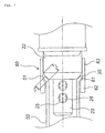
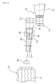
- Fig. 1 is a partial plane view for describing a connecting state of an inflator 10, a tube-like connecting member 50 and the fastening means 60.
- the inflator 10 shown in Fig. 1 is different from an inflator 100 shown in Fig. 9 in a shape of a surface (a surface of a distal end portion 30 of a main body portion 22) of a diffuser portion 20 as well as in that a screen 26 is provided, but it is identical to the inflator 100 shown in Fig. 9 in the not-illustrated other portions and the internal structure. Therefore, the description is made according to Fig. 1 and Fig. 9.
- the inflator 10 is provided with an inflator housing 12 in which a gas such as argon or helium is charged with a high pressure, a rupturing means accommodating chamber 14 connected to the inflator housing 12 (the inflator housing 12 and the rupturing means accommodating chamber 14 may be constituted with a single member formed integrally) , and a diffuser portion 20 connected to an opening portion provided on a side surface of the rupturing means accommodating chamber 14.
- a rupturable plate closes between the inflator housing 12 and the rupturing means accommodating chamber 14, and an electric igniter for rupturing the rupturable plate is accommodated in the rupturing means accommodating chamber 14.
- an embodiment in which the diffuser portion 20 is provided on the extension of a center axis of the inflator housing 12 may be employed.
- the diffuser portion 20 is a member for setting a discharging direction of a gas to be coaxial with the inflator housing 12, and it is mounted such that the center axis of the inflator housing 12 and the center axis of the diffuser portion 20 coincide with each other.
- the diffuser portion 20 is provided with a connecting portion (a diffuser connecting portion) 21, a main body portion (a diffuser main body portion) 22 and a protrusion portion (a diffuser protrusion portion) 23 having a predetermined number of gas discharging ports 25.
- a filter 26 for removing foreign matters (ruptured pieces of a ruptured rupturable plate) is provided inside the diffuser protrusion portion 23 to cover the gas discharging ports 25 from the inside.
- a surface of a distal end portion 30 of the diffuser main body portion 22 is formed in a convex spherical surface (convex-like arc of the sectional view in the axial line) and a male screw portion is formed on an outer peripheral surface in the vicinity of the distal end portion 30.
- the width of the spreading portion 51 is constant but it can be varied. When the width of the spreading portion 51 is varied, for example, a width of a half circle portion of the spreading portion may be smaller than the remaining half circle portion thereof. When the half circle portion of the spreading portion 51 is narrowed in this manner, since it becomes easier to incline the tube-like connecting member 50 in a direction of the narrowed spreading portion 51, it becomes easier to adjust the attaching direction.
- a similar constitution can be employed in embodiments shown in the following Fig. 2 to Fig. 7.
- a relationship of a length L 1 of an arc on a convex spherical surface of the distal end portion 30 of the diffuser main body portion 22 and a length L 2 of a straight line on a inclined surface of an inner peripheral surface of the spreading portion 51 meets L 1 ⁇ L 2 when the center axes of the diffuser portion 20 and the tube-like connecting member 50 coincide with each other as shown in Fig. 10. But it is preferable that, when an adjustment to a desired direction such as an X 1 or X 2 direction (a desired angle) is made, the relationship meets the L 1 > L 2 , as shown in Fig. 8.
- a nut 60 is a fastening means for fixing a connecting portion of the tube-like connecting member 50 and the diffuser main body portion 22.
- the nut 60 has a stepped portion 61 corresponding to a convex shape of the spreading portion 51 of the tube-like connecting member 50, and the stepped portion 61 divides the nut 60 into a thicker portion 62 and a thinner portion 63, and a female screw portion is provided on the thinner portion 63.
- a shape of an inner peripheral surface including the stepped portion 61 has a clearance (a space) which deals with a change by adjusting a clearance between the outer peripheral surface of the tube-like connecting member 50 and the inner peripheral surface of the thicker portion 62 or applying a recess to a step of the stepped portion 61 to deal with a predetermined abutting state between the stepped portion 61 and the spreading portion 51.
- a clearance a space
- the distal end portion 30 of the diffuser main body portion 22 has a convex spherical surface and the inner peripheral surface of the spreading portion 51 is a inclined surface, a contacting area is reduced and the attaching direction can be adjusted by slightly inclining the tube-like connecting member 50, so that the working degree of an inner surface of the nut 60 (a space) may be small.
- a position corresponding to the space may be covered with a flexible member (a rubber or the like) or a plastic member, or a portion corresponding to the space can be formed with a flexible member (a rubber or the like) or a plastic member in order to deal with a change of the abutting state of the stepped portion 61 and the spreading portion 51.
- the connecting portion of the diffuser main body portion 22 and the tube-like connecting member 50 is fixed by screwing the female screw portion of the nut 60 and the male screw portion of the main body portion 22 to each other.
- the attaching direction of the tube-like connecting member 50 is adjusted easier, (furthermore, if required, by adjusting to meet the relationship of the above-described L 1 ⁇ L 2 or L 1 > L 2 ) it is possible to adjust into a desired direction such as an X 1 or X 2 direction as shown in Fig. 8, in addition to adjusting into a direction in which the center axis of the diffuser portion 20 and the center axis of the tube-like connecting member 50 coincide with each other as shown in Fig. 10.
- the diffuser portion 20 and the tube-like connecting member 50 are fixed by screwing the nut 60, the outer peripheral surface of the spreading portion 51 is pressed axially by the stepped portion 61 of the nut 60, making the fixing more firmly.
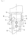
- Fig. 2 is a partial plane view for describing a connecting state of an inflator 10, the tube-like connecting member 50 and the fastening means 60.
- An inflator 10 shown in Fig. 2 is identical to the inflator 10 shown in Fig. 1.
- An opening edge of a tube-like connecting member 50 which abuts against a surface of the distal end portion 30 of the diffuser main body portion 22 has a spreading portion 51 expanded outwardly, and an inner peripheral surface of the spreading portion 51 is formed in a concave spherical surface (concave-like arc of the sectional view in the axial line) corresponding to a convex spherical surface of the distal end portion 30.
- a relationship between a length L 1 of an arc on a convex spherical surface (convex-like arc of the sectional view in the axial line) of the distal end portion 30 of the diffuser main body portion 22 and a length L 2 of an arc on a concave spherical surface of an inner peripheral surface of the spreading portion 51 meets L 1 ⁇ L 2 when the center axes of the diffuser portion 20 and the tube-like connecting member 50 coincide with each other as shown in Fig. 10. But it is desirable that, when adjustment to a desired direction such as an X 1 or X 2 direction (a desired angle) is made, the relationship meets the L 1 > L 2 as shown in Fig. 8.
- the nut 60 has a stepped portion 61 in a shape corresponding to the spreading portion 51 of the tube-like connecting member 50 and which deals with a change of abutting state with the expanded portion, the stepped portion 61 divides the nut 60 into a thicker portion 62 and a thinner portion 63 and a female screw portion is provided on the thinner portion 62.
- a connecting portion of the diffuser main body portion 22 and the tube-like connecting member 50 are fixed to each other by screwing the female screw portion of the nut 60 and the male screw portion of the main body portion 22 to each other.
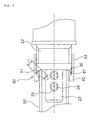
- Fig. 3 is a partial plane view for describing a connection state of an inflator 10, a tube-like connecting member 50 and a fastening means 60.
- the inflator 10 shown in Fig. 3 is identical to the inflator 10 shown in Fig. 1.
- An opening edge of a tube-like connecting member 50 which abuts against a surface of a distal end portion 30 of a diffuser main body portion 22 has a spreading portion 51 reduced inwardly, and an inner peripheral surface of the spreading portion 51 is formed in a inclined surface (an axial section slopes with respect to the axial direction, which is an inclined surface).
- the tube-like connecting member 50 has a protrusion portion 52 on an outer peripheral surface in the vicinity of the spreading portion 51.
- a relationship between a length L 1 of an arc on a convex spherical surface (convex-like arc of the sectional view in the axial line) of the distal end portion 30 of the diffuser main body portion 22 and a length L 2 of a straight line of the inclined surface on a concave spherical surface of an inner peripheral surface of the spreading portion 51 meets L 1 ⁇ L 2 when the center axes of the diffuser portion 20 and the tube-like connecting member 50 coincide with each other as shown in Fig. 10.
- a desired direction such as an X 1 or X 2 direction (a desired angle)
- the nut 60 has a stepped portion 61 provided on the outer surface of the spreading portion 51 of the tube-like connecting member 50 and in a shape corresponding to the protrusion portion 52, and the stepped portion 61 divides the nut 60 into a thicker portion 62 and a thinner portion 63 and a female screw portion is provided on the thinner portion 62.
- a connecting portion of the diffuser main body portion 22 and the tube-like connecting member 50 are fixed to each other by screwing the female screw portion of the nut 60 and the male screw portion of the main body portion 22.
- the attaching direction of the tube-like connecting member 50 is adjusted easily like the first embodiment, (further, if desired, by adjusting to meet the relationship of the above-described L 1 ⁇ L 2 or L 1 > L 2 ) it is possible to adjust into a desired direction such as an X 1 or X 2 direction as shown in Fig. 8, in addition to adjusting into a direction in which the center axis of the diffuser portion 20 and the center axis of the tube-like connecting member 50 coincide with each other as shown in Fig. 10.
- the protrusion portion 52 is pressed axially by a step 61 of the nut 60, making the fixing more firmly.
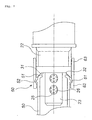
- Fig. 4 is a partial plane view for describing a connection state of an inflator 10, a tube-like connecting member 50 and fastening means 60.
- An inflator 10 shown in Fig. 4 is identical to the inflator 10 shown in Fig. 1.
- An opening edge of a tube-like connecting member 50 which abuts against a surface of a distal end portion 30 of a diffuser main body portion 22 has a spreading portion 51 reduced inwardly, and an inner peripheral surface of the spreading portion 51 is formed in a concave spherical surface (the surface whose axial section becomes a concave arc surface).
- the tube-like connecting member 50 has a protrusion portion 52 on an outer peripheral surface in the vicinity of the spreading portion 51.
- a relationship between a length L 1 of an arc on a convex spherical surface (convex-like arc of the sectional view in the axial line) of the distal end portion 30 of the diffuser main body portion 22 and a length L 2 of an arc of the concave spherical surface of an inner peripheral surface of the spreading portion 51 meets L 1 ⁇ L 2 when the center axes of the diffuser portion 20 and the tube-like connecting member 50 coincide with each other as shown in Fig. 10. But it is desirable that, when adjustment to a desired direction such as an X 1 or X 2 direction (a desired angle) is made, the relationship meets the L 1 > L 2 as shown in Fig. 8.
- the nut 60 has a stepped portion 61 in a shape of corresponding to the protrusion portion 52 of the tube-like connecting member 50, and the stepped portion 61 divides the nut 60 into a thicker portion 62, and a thinner portion 63 and a female screw portion is provided on the thinner portion 62.
- a connecting portion of the diffuser main body portion 22 and the tube-like connecting member 50 are fixed to each other by screwing the female screw portion of the nut 60 and the male screw portion of the main body portion 22.
- Fig. 5 is a partial plane view for describing a connecting state of an inflator 10, a tube-like connecting member 50 and fastening means 60.
- An inflator 10 shown in Fig. 5 is identical to the inflator 10 shown in Fig. 1 except that they are different in shape of a distal end portion 30 of a diffuser main body portion 22.
- a surface of the distal end portion 30 of the diffuser main body portion 22 is formed in a concave spherical surface (the surface whose axial section becomes a concave arc surface) .
- a male screw portion is formed on a peripheral surface in the vicinity of the distal end portion 30 of the diffuser main body portion 22.
- An opening edge of a tube-like connecting member 50 which abuts against a surface of the distal end portion 30 of the diffuser main body portion 22 has a spreading portion 51 expanded outwardly, and an inner peripheral surface of the spreading portion 51 is formed in a convex spherical surface (convex-like arc of the sectional view in the axial line).
- a relationship between a length L 1 of an arc on a concave spherical surface of the distal end portion 30 of the diffuser main body portion 22 and a length L 2 of an arc of the convex spherical surface of an inner peripheral surface of the spreading portion 51 meets L 1 ⁇ L 2 when the center axes of the diffuser portion 20 and the tube-like connecting member 50 coincide with each other as shown in Fig. 10. But it is desirable that, when adjustment to a desired direction such as an X 1 or X 2 direction (a desired angle) is made, the relationship meets the L 1 > L 2 as shown in Fig. 8.
- the nut 60 has a stepped portion 61 in a shape of corresponding to the spreading portion 51 of the tube-like connecting member 50 as well as in a shape which can deal with a change of abutting state with the expanded portion, and the stepped portion 61 divides the nut 60 into a thicker portion 62 and a thinner portion 63 and a female screw portion is provided on the thinner portion 62.
- a connecting portion between the diffuser main body portion 22 and the tube-like connecting member 50 is fixed to each other by screwing the female screw portion of the nut 60 and the male screw portion of the main body portion 22 to each other.
- Fig. 6 is a partial plane view for describing a connecting state of an inflator 10, a tube-like connecting member 50 and a fastening means 60.
- the inflator 10 shown in Fig. 6 is identical to the inflator 10 shown in Fig. 1 except that they are different in shape of the distal end portion 30 of the diffuser main body portion 22.
- a distal end portion 30 of the diffuser main body portion 22 has a shape obtained by combining a flat surface 31 and a inclined surface (a slanting surface) 32, and a male screw portion is formed on a peripheral surface in the vicinity of the distal end portion 30.
- An angle defined by the center axis and the inclined surface 32 of the diffuser portion 20 is set to 45 degrees.
- the total length of the flat surface 31 and the inclined surface 32 corresponds to L 1 .
- An opening edge of a tube-like connecting member 50 which abuts against a surface of the distal end portion 30 of the diffuser main body portion 22 has a spreading portion 51 expanded outwardly, and an outer peripheral surface of the spreading portion 51 is formed in a convex spherical surface (convex-like arc of the sectional view in the axial line).
- the tube-like connecting member 50 has a protrusion portion 52 on the outer surface in the vicinity of the spreading portion 51.
- the nut 60 has a stepped portion 61 in a shape corresponding to the protrusion portion 52 of the tube-like connecting member 50, and the stepped portion 61 divides the nut 60 into a thicker portion 62 and a thinner portion 63 and a female screw portion is provided on the thinner portion 62.
- a connecting portion between the diffuser main body portion 22 and the tube-like connecting member 50 is fixed to each other by screwing a female screw portion of the nut 60 and a male screw portion of the main body portion 22 to each other.
- Fig. 7 is a partial plane view for describing a connecting state of an inflator 10, a tube-like connecting member 50 and fastening means 60.
- the inflator 10 shown in Fig. 7 is identical to the inflator 10 shown in Fig. 6, and the tube-like connecting member 50 and the nut 60 are identical to those shown in Fig 5.
- An air bag system comprises an inflator, an impact sensor which detects an impact to actuate the gas generator, an air bag which introduces a gas generated in the gas generator to inflate and a module case which accommodates the air bag, and it may has the same constitution as that shown in Fig. 17 of JP-A 11-334517, for example.
- the inflator and the module case are connected to each other as shown in Fig. 10, and, as to a combination of the inflator, the tube-like connecting member and the fastening means, the embodiments shown in Fig. 1 to Fig. 7 can be applied.
- the positioning jig 65 is attached to the opening portion of the tube-like connecting member 50 in the side to which the module case is connected, the surface of the distal end 30 of the diffuser main body portion 22 abuts against the opening portion of the tube-like connecting member in the side to which the diffuser portion is connected, and, at the same time, the attaching direction of the tube-like connecting member 50 is adjusted.
- the surface of the distal end 30 of the diffuser main body portion 22 abuts against the opening portion of the tube-like connecting member 50 in the side to which the diffuser portion is connected, and, at the same time, the positioning jig 65 is attached to the opening portion of the tube-like connecting member 50 in the side to which the module case is connected after the direction of the central axis of the tube-like connecting member 50 is adjusted.
- the positioning jig 65 is for preventing deviation in the attaching direction of the tube-like connecting member 50 due to a force applied at the time of fixing with the fastening means (nut) 60 in the next Process 3. Therefore, any jig can be used as long as it can be inserted into the opening portion of the tube-like connecting member 50 in the side to which the module case is connected, or it can sheathe the opening portion to support.
- the tube-like connecting member 50 may be deviated from a desired attaching direction by a force applied at the time of fastening with the fastening means 60.
- a deviation never occurs in the attaching direction of the tube-like connecting member 50 even at a time of fastening.
- the inflator, the tube-like connecting member, the air bag system and the method of attaching an inflator of the present invention can be applied to various inflators such as an inflator for an air bag for a driver side, an inflator for an air bag for a passenger side next to the driver, an inflator for an air bag for side collision, an inflator for an curtain air bag, an inflator for a knee-bolster air bag, an inflator for an inflatable seat belt, an inflator for a tubular system, and an inflator for a pretensioner, and air bag systems including these inflators.
- various inflators such as an inflator for an air bag for a driver side, an inflator for an air bag for a passenger side next to the driver, an inflator for an air bag for side collision, an inflator for an curtain air bag, an inflator for a knee-bolster air bag, an inflator for an inflatable seat belt, an inflator for a tubular system, and an inflator
Landscapes
- Physics & Mathematics (AREA)
- Fluid Mechanics (AREA)
- Engineering & Computer Science (AREA)
- Mechanical Engineering (AREA)
- Air Bags (AREA)
Abstract
The present invention provides a method of attaching an
inflator to a module case.
The present invention is a method of attaching an inflator
to a module case which comprises the following assembling
processes 1 to 4.
Description
The present invention relates to an inflator improved in
a secure and easy attachment to a module case accommodating an
air bag, a tube-like connecting member used for the attachment,
an air bag system using the inflator and the tube-like
connecting member, and a method of attaching an inflator to a
module case.
In an air bag system for protecting a passenger from the
impact at a vehicle collision, an inflator is connected to a
module case accommodating an air bag, and the air bag is inflated
by ejecting an inflating medium from the inflator. Therefore,
it is necessary to connect the module case and the inflator
securely, and also, an assembling at a time of assembling work
has to be facilitated.
As shown in Fig. 9, a conventional inflator 100 has an
inflator housing 12 in which a gas such as argon, helium or the
like is charged with a high pressure, a rupturing means
accommodating chamber 14 connected to the inflator housing 12
(the inflator housing 12 and the rupturing means accommodating
chamber 14 may be formed integrally to be a single member) , and
a diffuser portion 20 connected to the rupturing means
accommodating chamber 14, and a surface of a distal end portion
30 of the diffuser 20 is formed to be a inclined surface (the
axial section slops in the axial direction, which is a inclined
surface).
In an air bag system, as shown in Fig. 10, the inflator
100 and a module case 70 accommodating an air bag 71 are connected
to each other through a tube-like connecting member 50, and the
tube-like connecting member 50 is fixed by a nut 60 disposed
over a diffuser protrusion portion 23 and a diffuser main body
portion 22. In this case, an inner peripheral surface and an
outer peripheral surface of a spreading portion 51 provided at
an opening edge of one end (an opening edge contacting a surface
of the distal end portion 30) in the tube-like connecting member
50 are inclined surfaces (the axial section slops in the axial
direction, which is a inclined surface).
In an aspect shown in Fig. 10, the center axes of the
diffuser portion 20 and the tube-like connecting member 50
coincide with each other. However, a shape or a structure of
a module case are miscellaneous and a mounted state of a module
case to a vehicle varies according to a kind of a vehicle.
Therefore, in some cases, it is desirable that, when the
inflator is attached to the module case, the center axis of the
tube-like connecting member and the center axis of the diffuser
member are not coincident with each other. In such a case, as
shown in Fig. 8, it is required to adjust the attaching direction
such that the center axis of the tube-like connecting member
50 becomes X1 or X2, that is, to adjust an angle formed by the
center axis X of the diffuser portion 20 and the center axis
X1 or X2 of the tube-like connecting member 50 (the attaching
angle of the tube-like connecting member, which is the attaching
direction of the tube-like connecting member).
However, as described above, since the inclined surface
of the spreading portion 51 provided at the opening edge of the
one end in the tube-like connecting member 50 abuts against and
is fixed to a inclined surface of the distal end portion 30 of
the diffuser portion 20, the attaching angle of the tube-like
connecting member 50 is determined accordingly, so that it
becomes difficult to adjust the attaching angle to a desired
angle. In addition, when a working precision of a surface of
the distal end portion 30 which abuts against the spreading
portion 51 of the tube-like connecting member 50 at attaching
is coarse, the attaching angle of the tube-like connecting
member may be restricted to an angle different from an angle
intended originally. Further, since the tube-like connecting
member 50 having a size of about 0.5 to 1 m is used according
to a kind of a vehicle, a slight deviation of a proximal portion
(in the diffuser portion 20 side) causes a large deviation of
the distal end portion (in a module case 70 side), so that the
above-described angle adjustment becomes more difficult.
Furthermore, conventionally, when the inflator 100 is
attached to the module case 70, the following assembling
procedure is conducted. First, the inflator 100 is fixed at
the inflator housing 12. Next, after the spreading portion 51
of the tube-like connecting member 50 is made to abut against
the distal end portion 30 and the direction of the tube-like
connecting member 50 is adjusted, the diffuser portion 20 and
the nut 60 are screwed to each other to fix the tube-like
connecting member 50 to the diffuser portion 20. Thereafter,
the tube-like connecting member 50 is inserted into the module
case 70.
In such a procedure, however, there may occur such a case
that the attaching angle of the tube-like connecting member 50
once adjusted is deviated due to a force applied when the
diffuser portion 20 and the nut 60 are screwed and fixed to each
other, so that re-adjustment is required. When the tube-like
connecting member is forcibly inserted into the module case in
a state that the angle has been deviated in this manner, there
may also occur such a case that the module case 70 pressed by
the tube-like connecting member 50 deforms.
As described above, in the conventional inflator, a
working to attach the inflator to the module case is
unsatisfactory for various reasons, and in some conventional
attaching methods, the working at the time of attachment to the
module case is unsatisfactory, which is required to be improved.
An object of the present invention is to provide an
inflator with improved capability for attachment which can
securely and easily be attached to a module case accommodating
an air bag, a tube-like connecting member used for the
attachment, an air bag system using the inflator and the
tube-like connecting member, and a method of attaching an
inflator to a module case.
The invention described in claim 1 provides, as one means
for solving the above-described problem, an inflator with
improved capability for attachment comprising an inflator
housing in which a pressurized medium is charged as an inflating
medium for an air bag and a diffuser portion which is fixed to
the inflator housing and is provided with a gas discharging port
for discharging the pressurized medium outside at actuation,
wherein
when the inflator is attached to a module case accommodating an air bag, the diffuser portion and the module case are connected to each other through a tube-like connecting member, and a surface of the diffuser portion which abuts against an opening edge of one end in the tube-like connecting member at a time of attachment is a convex spherical surface, a concave spherical surface or a concave inclined surface.
when the inflator is attached to a module case accommodating an air bag, the diffuser portion and the module case are connected to each other through a tube-like connecting member, and a surface of the diffuser portion which abuts against an opening edge of one end in the tube-like connecting member at a time of attachment is a convex spherical surface, a concave spherical surface or a concave inclined surface.
In the above invention, it is preferable that the diffuser
portion has a connecting portion to the inflator housing, a main
body portion and a protrusion portion having a gas discharging
port, and a surface of a distal end portion of the main body
portion which abuts against the opening edge of the one end in
the tube-like connecting member at the time of attachment is
a convex spherical surface, a concave spherical surface or a
concave curved surface.
In this manner, by forming the surface of the diffuser
portion, preferably the surface of the distal end portion of
the main body portion in the diffuser portion into a convex
spherical surface, a concave spherical surface or concave
curved surface, it is unnecessary to set the opening edge of
the one end in the tube-like connecting member to a specific
shape, and even if a working precision is insufficient, the
attaching direction of the tube-like connecting member is
adjusted easily to a desired direction.
The invention described in claim 3 provides, as one means
for solving the above-described problem, a tube-like connecting
member which is used at the time of attaching the inflator
according to claim 1 or 2 to a module case accommodating an air
bag, wherein an opening edge of one end in the tube-like
connecting member which abuts against a surface of the diffuser
portion in a shape of a convex spherical surface, a concave
spherical surface or a concave inclined surface has a spreading
portion expanded outwardly or reduced inwardly, and an inner
peripheral surface or an outer peripheral surface of the
spreading portion is a inclined surface or a spherical surface.
By forming the inner peripheral surface of the spreading
portion provided at the opening edge of the one end in the
tube-like connecting member into the inclined surface or the
spherical surface in this manner, even if the working precision
of an inner peripheral surface or an outer peripheral surface
of the spreading portion is insufficient and the surface is
coarse, the attaching direction of the tube-like connecting
member can be adjusted to a desired direction (for example, the
direction of X1 or X2 shown in Fig. 8).
In the above invention, as described below, by relating
the surface of the diffuser portion and the shape of the
spreading portion of the opening edge of the one end in the
tube-like connecting member to each other, the attaching
direction of the tube-like connecting member is adjusted easily
to the desired direction at the time of attachment.
In the above invention, it is preferable that a
protrusion portion is provided on an outer peripheral surface
in the vicinity of the spreading portion of the tube-like
connecting member. When such a protrusion portion is provided,
a fixing effect is enhanced by a fastening means.
The invention described in claim 8 provides, as one means
for solving the above-described problem, an air bag system
comprising the inflator according to in claim 1 or 2, an impact
sensor which detects an impact to actuate the inflator, an air
bag in which a gas generated in the inflator is introduced to
be inflated, and a module case which accommodates the air bag,
wherein
a diffuser portion of the inflator and the module case in which the air bag is accommodated are connected to each other through the tube-like connecting member according to any one of claims 3 to 7.
a diffuser portion of the inflator and the module case in which the air bag is accommodated are connected to each other through the tube-like connecting member according to any one of claims 3 to 7.
In such air bag system, since a capability for attaching
the inflator to the module case is excellent, an assembling work
is facilitated and a deformation or the like of the module case
never occurs.
In the above invention, preferably, a connecting portion
between the diffuser portion of the inflator and the tube-like
connecting member according to any one of claims 3 to 7 is fixed
from the outside.
In the above invention, preferably, a male screw potion
is formed on an outer peripheral surface of the diffuser portion,
and a female screw portion is formed on an inner peripheral
surface of the fastening means, so that the diffuser portion
and the fastening means are fixed by screwing.
In the above invention, preferably, the fastening means
has a concave inner surface corresponding to a convex of the
outer surface of the tube-like connecting member. By using such
a fastening means, it becomes easier to adjust the attaching
direction of the tube-like connecting member at the time of
attachment.
The invention described in claim 12 provides, as one means
for solving the above-described problem, a method of attaching
an inflator, which is a method of attaching the inflator
according to claim 1 or 2 to a module case accommodating an air
bag with using the tube-like connecting member according to any
one of claims 3 to 7, wherein the attachment is performed
according to the following assembling processes 1 to 4.
According to the above-described method of attaching the
inflator, since the direction of the center axis of the
tube-like connecting member can be adjusted to a desired
direction in Process 2, an attaching work in the module case
is made easier. Further, by attaching the positioning jig in
Process 2, the attaching direction of the tube-like connecting
member can be fixed. Furthermore, even if fastening and fixing
are conducted by the fastening means in Process 3, the attaching
direction of the tube-like connecting member adjusted in
Process 2 is prevented from being deviated by a force applied
at the time of fastening.
By combining the inflator and the tube-like connection
means in the present invention to attach the inflator to the
module case, the attaching direction of the tube-like
connecting member can be adjusted to a desired direction. For
this reason, the attaching work for the inflator is made easier,
so that working is largely improved.
Embodiments including the above-described first to
fourth solving means will be explained as follows with reference
to the drawings attached to this specification.
Fig. 1 is a partial plane view for describing a connecting
state of an inflator 10, a tube-like connecting member 50 and
the fastening means 60. The inflator 10 shown in Fig. 1 is
different from an inflator 100 shown in Fig. 9 in a shape of
a surface (a surface of a distal end portion 30 of a main body
portion 22) of a diffuser portion 20 as well as in that a screen
26 is provided, but it is identical to the inflator 100 shown
in Fig. 9 in the not-illustrated other portions and the internal
structure. Therefore, the description is made according to Fig.
1 and Fig. 9.
The inflator 10 is provided with an inflator housing 12
in which a gas such as argon or helium is charged with a high
pressure, a rupturing means accommodating chamber 14 connected
to the inflator housing 12 (the inflator housing 12 and the
rupturing means accommodating chamber 14 may be constituted
with a single member formed integrally) , and a diffuser portion
20 connected to an opening portion provided on a side surface
of the rupturing means accommodating chamber 14. A rupturable
plate closes between the inflator housing 12 and the rupturing
means accommodating chamber 14, and an electric igniter for
rupturing the rupturable plate is accommodated in the rupturing
means accommodating chamber 14. Incidentally, besides the
embodiment shown in Fig. 9, an embodiment in which the diffuser
portion 20 is provided on the extension of a center axis of the
inflator housing 12 may be employed.
The diffuser portion 20 is a member for setting a
discharging direction of a gas to be coaxial with the inflator
housing 12, and it is mounted such that the center axis of the
inflator housing 12 and the center axis of the diffuser portion
20 coincide with each other. The diffuser portion 20 is
provided with a connecting portion (a diffuser connecting
portion) 21, a main body portion (a diffuser main body portion)
22 and a protrusion portion (a diffuser protrusion portion) 23
having a predetermined number of gas discharging ports 25. A
filter 26 for removing foreign matters (ruptured pieces of a
ruptured rupturable plate) is provided inside the diffuser
protrusion portion 23 to cover the gas discharging ports 25 from
the inside.
A surface of a distal end portion 30 of the diffuser main
body portion 22 is formed in a convex spherical surface
(convex-like arc of the sectional view in the axial line) and
a male screw portion is formed on an outer peripheral surface
in the vicinity of the distal end portion 30.
An opening edge of a tube-like connecting member 50 which
abuts against a surface of the distal end portion 30 of the
diffuser main body portion 22 has a spreading portion 51
expanded outwardly, and an inner peripheral surface of the
spreading portion 51 is formed in inclined surface (an axial
section slopes with respect to the axial direction = an inclined
surface). The width of the spreading portion 51 is constant
but it can be varied. When the width of the spreading portion
51 is varied, for example, a width of a half circle portion of
the spreading portion may be smaller than the remaining half
circle portion thereof. When the half circle portion of the
spreading portion 51 is narrowed in this manner, since it
becomes easier to incline the tube-like connecting member 50
in a direction of the narrowed spreading portion 51, it becomes
easier to adjust the attaching direction. A similar
constitution can be employed in embodiments shown in the
following Fig. 2 to Fig. 7.
A relationship of a length L1 of an arc on a convex
spherical surface of the distal end portion 30 of the diffuser
main body portion 22 and a length L2 of a straight line on a
inclined surface of an inner peripheral surface of the spreading
portion 51 meets L1 ≥ L2 when the center axes of the diffuser
portion 20 and the tube-like connecting member 50 coincide with
each other as shown in Fig. 10. But it is preferable that, when
an adjustment to a desired direction such as an X1 or X2 direction
(a desired angle) is made, the relationship meets the L1 > L2,
as shown in Fig. 8.
A nut 60 is a fastening means for fixing a connecting
portion of the tube-like connecting member 50 and the diffuser
main body portion 22. The nut 60 has a stepped portion 61
corresponding to a convex shape of the spreading portion 51 of
the tube-like connecting member 50, and the stepped portion 61
divides the nut 60 into a thicker portion 62 and a thinner portion
63, and a female screw portion is provided on the thinner portion
63.
An outer peripheral surface of the spreading portion 51
of the tube-like connecting member 50 abuts against the stepped
portion 61 of the nut 60, but an abutting state between the
stepped portion 61 and the spreading portion 51 varies depending
on the attaching direction of the tube-like connecting member
50. For this reason, it is desirable that a shape of an inner
peripheral surface including the stepped portion 61 has a
clearance (a space) which deals with a change by adjusting a
clearance between the outer peripheral surface of the tube-like
connecting member 50 and the inner peripheral surface of
the thicker portion 62 or applying a recess to a step of the
stepped portion 61 to deal with a predetermined abutting state
between the stepped portion 61 and the spreading portion 51.
In the inflator 10 shown in Fig. 1, since the distal end portion
30 of the diffuser main body portion 22 has a convex spherical
surface and the inner peripheral surface of the spreading
portion 51 is a inclined surface, a contacting area is reduced
and the attaching direction can be adjusted by slightly
inclining the tube-like connecting member 50, so that the
working degree of an inner surface of the nut 60 (a space) may
be small. A position corresponding to the space may be covered
with a flexible member (a rubber or the like) or a plastic member,
or a portion corresponding to the space can be formed with a
flexible member (a rubber or the like) or a plastic member in
order to deal with a change of the abutting state of the stepped
portion 61 and the spreading portion 51.
The connecting portion of the diffuser main body portion
22 and the tube-like connecting member 50 is fixed by screwing
the female screw portion of the nut 60 and the male screw portion
of the main body portion 22 to each other.
,In the embodiment shown in Fig. 1, since the distal end
portion 30 of the diffuser main body portion 22 is formed in
a convex spherical surface and the spreading portion 51 of the
tube-like connecting member 50 has a inclined surface, the
attaching direction of the tube-like connecting member 50 is
adjusted easier, (furthermore, if required, by adjusting to
meet the relationship of the above-described L1 ≥ L2 or L1 > L2)
it is possible to adjust into a desired direction such as an
X1 or X2 direction as shown in Fig. 8, in addition to adjusting
into a direction in which the center axis of the diffuser portion
20 and the center axis of the tube-like connecting member 50
coincide with each other as shown in Fig. 10.
Furthermore, when the diffuser portion 20 and the
tube-like connecting member 50 are fixed by screwing the nut
60, the outer peripheral surface of the spreading portion 51
is pressed axially by the stepped portion 61 of the nut 60, making
the fixing more firmly.
Fig. 2 is a partial plane view for describing a connecting
state of an inflator 10, the tube-like connecting member 50 and
the fastening means 60. An inflator 10 shown in Fig. 2 is
identical to the inflator 10 shown in Fig. 1.
An opening edge of a tube-like connecting member 50 which
abuts against a surface of the distal end portion 30 of the
diffuser main body portion 22 has a spreading portion 51
expanded outwardly, and an inner peripheral surface of the
spreading portion 51 is formed in a concave spherical surface
(concave-like arc of the sectional view in the axial line)
corresponding to a convex spherical surface of the distal end
portion 30.
A relationship between a length L1 of an arc on a convex
spherical surface (convex-like arc of the sectional view in the
axial line) of the distal end portion 30 of the diffuser main
body portion 22 and a length L2 of an arc on a concave spherical
surface of an inner peripheral surface of the spreading portion
51 meets L1 ≥ L2 when the center axes of the diffuser portion
20 and the tube-like connecting member 50 coincide with each
other as shown in Fig. 10. But it is desirable that, when
adjustment to a desired direction such as an X1 or X2 direction
(a desired angle) is made, the relationship meets the L1 > L2
as shown in Fig. 8.
The nut 60 has a stepped portion 61 in a shape
corresponding to the spreading portion 51 of the tube-like
connecting member 50 and which deals with a change of abutting
state with the expanded portion, the stepped portion 61 divides
the nut 60 into a thicker portion 62 and a thinner portion 63
and a female screw portion is provided on the thinner portion
62.
A connecting portion of the diffuser main body portion
22 and the tube-like connecting member 50 are fixed to each other
by screwing the female screw portion of the nut 60 and the male
screw portion of the main body portion 22 to each other.
In the embodiment shown in Fig. 2, since the distal end
portion 30 of the diffuser main body portion 22 is formed in
the convex spherical surface and the inner peripheral surface
of the spreading portion 51 of the tube-like connecting member
51 is formed in the concave spherical surface, (further, if
desired, by adjusting to meet the relationship of the
above-described L1 ≥ L2 or L1 > L2), at the time of abutting the
spreading portion 51 of the tube-like connecting member 50, it
is possible to easily adjust an attaching direction of the
tube-like connecting member 50 only by sliding, with abutting
the convex spherical surface of the distal end portion 30
against the inner peripheral surface (the concave spherical
surface) of the spreading portion 51. For this reason, it is
possible to adjust into a desired direction such as an X1 or
X2 direction as shown in Fig. 8, in addition to adjusting into
a direction in which the center axis of the diffuser portion
20 and the center axis of the tube-like connecting member 50
coincide with each other as shown in Fig. 10.
Furthermore, when the diffuser portion 20 and the
tube-like connecting member 50 are fixed to each other by
screwing the nut 60, an outer peripheral surface of the
spreading portion 51 is pressed axially by the stepped portion
61 of the nut 60, making the fixing more firmly.
Fig. 3 is a partial plane view for describing a connection
state of an inflator 10, a tube-like connecting member 50 and
a fastening means 60. The inflator 10 shown in Fig. 3 is
identical to the inflator 10 shown in Fig. 1.
An opening edge of a tube-like connecting member 50 which
abuts against a surface of a distal end portion 30 of a diffuser
main body portion 22 has a spreading portion 51 reduced inwardly,
and an inner peripheral surface of the spreading portion 51 is
formed in a inclined surface (an axial section slopes with
respect to the axial direction, which is an inclined surface).
The tube-like connecting member 50 has a protrusion portion 52
on an outer peripheral surface in the vicinity of the spreading
portion 51.
A relationship between a length L1 of an arc on a convex
spherical surface (convex-like arc of the sectional view in the
axial line) of the distal end portion 30 of the diffuser main
body portion 22 and a length L2 of a straight line of the inclined
surface on a concave spherical surface of an inner peripheral
surface of the spreading portion 51 meets L1 ≥ L2 when the center
axes of the diffuser portion 20 and the tube-like connecting
member 50 coincide with each other as shown in Fig. 10. But
it is desirable that, when adjustment to a desired direction
such as an X1 or X2 direction (a desired angle) is made, the
relationship meets the L1 > L2 as shown in Fig. 8.
The nut 60 has a stepped portion 61 provided on the outer
surface of the spreading portion 51 of the tube-like connecting
member 50 and in a shape corresponding to the protrusion portion
52, and the stepped portion 61 divides the nut 60 into a thicker
portion 62 and a thinner portion 63 and a female screw portion
is provided on the thinner portion 62.
A connecting portion of the diffuser main body portion
22 and the tube-like connecting member 50 are fixed to each other
by screwing the female screw portion of the nut 60 and the male
screw portion of the main body portion 22.
In the embodiment shown in Fig. 3, since the distal end
portion 30 of the diffuser main body portion 22 is formed in
a convex spherical surface and an inner peripheral surface of
the spreading portion 51 of the tube-like connecting member 50
is a inclined surface, the attaching direction of the tube-like
connecting member 50 is adjusted easily like the first
embodiment, (further, if desired, by adjusting to meet the
relationship of the above-described L1 ≥ L2 or L1 > L2) it is
possible to adjust into a desired direction such as an X1 or
X2 direction as shown in Fig. 8, in addition to adjusting into
a direction in which the center axis of the diffuser portion
20 and the center axis of the tube-like connecting member 50
coincide with each other as shown in Fig. 10.
Furthermore, when the diffuser portion 20 and the
tube-like connecting member 50 are fixed by screwing the nut
60, the protrusion portion 52 is pressed axially by a step 61
of the nut 60, making the fixing more firmly.
Fig. 4 is a partial plane view for describing a connection
state of an inflator 10, a tube-like connecting member 50 and
fastening means 60. An inflator 10 shown in Fig. 4 is identical
to the inflator 10 shown in Fig. 1.
An opening edge of a tube-like connecting member 50 which
abuts against a surface of a distal end portion 30 of a diffuser
main body portion 22 has a spreading portion 51 reduced inwardly,
and an inner peripheral surface of the spreading portion 51 is
formed in a concave spherical surface (the surface whose axial
section becomes a concave arc surface). The tube-like
connecting member 50 has a protrusion portion 52 on an outer
peripheral surface in the vicinity of the spreading portion 51.
A relationship between a length L1 of an arc on a convex
spherical surface (convex-like arc of the sectional view in the
axial line) of the distal end portion 30 of the diffuser main
body portion 22 and a length L2 of an arc of the concave spherical
surface of an inner peripheral surface of the spreading portion
51 meets L1 ≥ L2 when the center axes of the diffuser portion
20 and the tube-like connecting member 50 coincide with each
other as shown in Fig. 10. But it is desirable that, when
adjustment to a desired direction such as an X1 or X2 direction
(a desired angle) is made, the relationship meets the L1 > L2
as shown in Fig. 8.
The nut 60 has a stepped portion 61 in a shape of
corresponding to the protrusion portion 52 of the tube-like
connecting member 50, and the stepped portion 61 divides the
nut 60 into a thicker portion 62, and a thinner portion 63 and
a female screw portion is provided on the thinner portion 62.
A connecting portion of the diffuser main body portion
22 and the tube-like connecting member 50 are fixed to each other
by screwing the female screw portion of the nut 60 and the male
screw portion of the main body portion 22.
In the embodiment shown in Fig. 4, since the distal end
portion 30 of the diffuser main body portion 22 is formed in
the convex spherical surface and the inner peripheral surface
of the spreading portion 51 of the tube-like connecting member
51 is formed in the concave spherical surface, (further, if
desired, by adjusting to meet the relationship of the
above-described L1 ≥ L2 or L1 > L2), at the time of abutting the
spreading portion 51 of the tube-like connecting member 50, it
is possible to easily adjust an attaching direction of the
tube-like connecting member 50 like Embodiment 2. Therefore,
it is possible to adjust into a desired direction such as an
X1 or X2 direction as shown in Fig. 8, in addition to adjusting
into a direction in which the center axis of the diffuser portion
20 and the center axis of the tube-like connecting member 50
coincide with each other as shown in Fig. 10.
Furthermore, when the diffuser portion 20 and the
tube-like connecting member 50 are fixed to each other by
screwing the nut 60, a protrusion portion 52 is pressed axially
by the stepped portion 62 of the nut 60, making the fixing more
firmly.
Fig. 5 is a partial plane view for describing a connecting
state of an inflator 10, a tube-like connecting member 50 and
fastening means 60. An inflator 10 shown in Fig. 5 is identical
to the inflator 10 shown in Fig. 1 except that they are different
in shape of a distal end portion 30 of a diffuser main body
portion 22.
A surface of the distal end portion 30 of the diffuser
main body portion 22 is formed in a concave spherical surface
(the surface whose axial section becomes a concave arc surface) .
A male screw portion is formed on a peripheral surface in the
vicinity of the distal end portion 30 of the diffuser main body
portion 22.
An opening edge of a tube-like connecting member 50 which
abuts against a surface of the distal end portion 30 of the
diffuser main body portion 22 has a spreading portion 51
expanded outwardly, and an inner peripheral surface of the
spreading portion 51 is formed in a convex spherical surface
(convex-like arc of the sectional view in the axial line).
A relationship between a length L1 of an arc on a concave
spherical surface of the distal end portion 30 of the diffuser
main body portion 22 and a length L2 of an arc of the convex
spherical surface of an inner peripheral surface of the
spreading portion 51 meets L1 ≥ L2 when the center axes of the
diffuser portion 20 and the tube-like connecting member 50
coincide with each other as shown in Fig. 10. But it is
desirable that, when adjustment to a desired direction such as
an X1 or X2 direction (a desired angle) is made, the relationship
meets the L1 > L2 as shown in Fig. 8.
The nut 60 has a stepped portion 61 in a shape of
corresponding to the spreading portion 51 of the tube-like
connecting member 50 as well as in a shape which can deal with
a change of abutting state with the expanded portion, and the
stepped portion 61 divides the nut 60 into a thicker portion
62 and a thinner portion 63 and a female screw portion is provided
on the thinner portion 62.
A connecting portion between the diffuser main body
portion 22 and the tube-like connecting member 50 is fixed to
each other by screwing the female screw portion of the nut 60
and the male screw portion of the main body portion 22 to each
other.
In the embodiment shown in Fig. 5, since the distal end
portion 30 of the diffuser main body portion 22 is formed in
the concave spherical surface and the inner peripheral surface
of the spreading portion 51 of the tube-like connecting member
51 is formed in the convex spherical surface, (further, if
desired, by adjusting to meet the relationship of the
above-described L1 ≥ L2 or L1 > L2), at the time of abutting the
spreading portion 51 of the tube-like connecting member 50, it
is possible to easily adjust an attaching direction of the
tube-like connecting member 50 like Embodiment 2. Therefore,
it is possible to adjust into a desired direction such as an
X1 or X2 direction as shown in Fig. 8, in addition to adjusting
into a direction in which the center axis of the diffuser portion
20 and the center axis of the tube-like connecting member 50
coincide with each other as shown in Fig. 10.
Furthermore, when the diffuser portion 20 and the
tube-like connecting member 50 are fixed to each other by
screwing the nut 60, an outer peripheral surface of the
spreading portion 51 is pressed axially by the stepped portion
61 of the nut 60, making the fixing more firmly.
Fig. 6 is a partial plane view for describing a connecting
state of an inflator 10, a tube-like connecting member 50 and
a fastening means 60. The inflator 10 shown in Fig. 6 is
identical to the inflator 10 shown in Fig. 1 except that they
are different in shape of the distal end portion 30 of the
diffuser main body portion 22.
A distal end portion 30 of the diffuser main body portion
22 has a shape obtained by combining a flat surface 31 and a
inclined surface (a slanting surface) 32, and a male screw
portion is formed on a peripheral surface in the vicinity of
the distal end portion 30. An angle defined by the center axis
and the inclined surface 32 of the diffuser portion 20 is set
to 45 degrees. Here, the total length of the flat surface 31
and the inclined surface 32 corresponds to L1.
An opening edge of a tube-like connecting member 50 which
abuts against a surface of the distal end portion 30 of the
diffuser main body portion 22 has a spreading portion 51
expanded outwardly, and an outer peripheral surface of the
spreading portion 51 is formed in a convex spherical surface
(convex-like arc of the sectional view in the axial line). The
tube-like connecting member 50 has a protrusion portion 52 on
the outer surface in the vicinity of the spreading portion 51.
The nut 60 has a stepped portion 61 in a shape
corresponding to the protrusion portion 52 of the tube-like
connecting member 50, and the stepped portion 61 divides the
nut 60 into a thicker portion 62 and a thinner portion 63 and
a female screw portion is provided on the thinner portion 62.
The relationship between the total length L1 of the flat
surface 31 and the inclined surface 32 and a length L2 of an
arc on a convex spherical surface on an outer peripheral surface
of the spreading portion 51 meets L1 > L2.
A connecting portion between the diffuser main body
portion 22 and the tube-like connecting member 50 is fixed to
each other by screwing a female screw portion of the nut 60 and
a male screw portion of the main body portion 22 to each other.
In the embodiment shown in Fig. 6, since the distal end
portion 30 of the diffuser main body portion 22 is an inclined
portion 32 and the outer peripheral surface of the spreading
portion 51 of the tube-like connecting member 51 is formed in
the convex spherical surface, it is possible to easily adjust
an attaching direction of the tube-like connecting member 50
like Embodiment 1. And further, because of L1 > L2, it is
possible to adjust into a desired direction such as an X1 or
X2 direction as shown in Fig. 8, in addition to adjusting into
a direction in which the center axes of the diffuser portion
20 and the tube-like connecting member 50 coincide with each
other as shown in Fig. 10.
Furthermore, when the diffuser portion 20 and the
tube-like connecting member 50 are fixed to each other by
screwing the nut 60, a protrusion portion 52 is pressed axially
by the stepped portion 61 of the nut 60, making the fixing more
firmly.
Fig. 7 is a partial plane view for describing a connecting
state of an inflator 10, a tube-like connecting member 50 and
fastening means 60. The inflator 10 shown in Fig. 7 is identical
to the inflator 10 shown in Fig. 6, and the tube-like connecting
member 50 and the nut 60 are identical to those shown in Fig
5.
In the embodiment shown in Fig. 7, since the distal end
portion 30 of the diffuser main body portion 22 is an inclined
portion 32 and the outer peripheral surface of the spreading
portion 51 of the tube-like connecting member 51 is formed in
the convex spherical surface, it is possible to easily adjust
an attaching direction of the tube-like connecting member 50
like Embodiment 1. And further, because of L1 > L2, it is
possible to adjust into a desired direction such as an X1 or
X2 direction as shown in Fig. 8, in addition to adjusting into
a direction in which the center axis of the diffuser portion
20 and the center axis of the tube-like connecting member 50
coincide with each other as shown in Fig. 10.
Furthermore, when the diffuser portion 20 and the
tube-like connecting member 50 are fixed to each other by
screwing the nut 60, a spreading portion 51 is pressed axially
by the stepped portion 61 of the nut 60, making the fixing more
firmly.
An air bag system comprises an inflator, an impact sensor
which detects an impact to actuate the gas generator, an air
bag which introduces a gas generated in the gas generator to
inflate and a module case which accommodates the air bag, and
it may has the same constitution as that shown in Fig. 17 of
JP-A 11-334517, for example.
In the air bag system, for example, the inflator and the
module case are connected to each other as shown in Fig. 10,
and, as to a combination of the inflator, the tube-like
connecting member and the fastening means, the embodiments
shown in Fig. 1 to Fig. 7 can be applied.
An attaching method of an inflator according to the
assembling processes 1 to 4 will be explained with reference
to Fig. 8. First, in Process 1, the inflator 10 (the inflator
housing 12) is fixed by fixing means.
Next, in Process 2, the positioning jig 65 is attached
to the opening portion of the tube-like connecting member 50
in the side to which the module case is connected, the surface
of the distal end 30 of the diffuser main body portion 22 abuts
against the opening portion of the tube-like connecting member
in the side to which the diffuser portion is connected, and,
at the same time, the attaching direction of the tube-like
connecting member 50 is adjusted.
In this Process 2, the surface of the distal end 30 of
the diffuser main body portion 22 abuts against the opening
portion of the tube-like connecting member 50 in the side to
which the diffuser portion is connected, and, at the same time,
the positioning jig 65 is attached to the opening portion of
the tube-like connecting member 50 in the side to which the
module case is connected after the direction of the central axis
of the tube-like connecting member 50 is adjusted.
The positioning jig 65 is for preventing deviation in the
attaching direction of the tube-like connecting member 50 due
to a force applied at the time of fixing with the fastening means
(nut) 60 in the next Process 3. Therefore, any jig can be used
as long as it can be inserted into the opening portion of the
tube-like connecting member 50 in the side to which the module
case is connected, or it can sheathe the opening portion to
support.
Next, in Process 4, the connecting portion between the
diffuser portion 20 and the tube-like connecting member 50 is
fixed from the outside by the fastening means 60.
If the positioning jig 65 is not used, the tube-like
connecting member 50 may be deviated from a desired attaching
direction by a force applied at the time of fastening with the
fastening means 60. However, by fitting the positioning jig
65 into the opening portion 55 of the tube-like connecting
member 50 in the side to which the module case is connected in
order to support the same, a deviation never occurs in the
attaching direction of the tube-like connecting member 50 even
at a time of fastening.
Next, in Process 5, the positioning jig 65 is removed and
the tube-like connecting member 50 is inserted into the module
case 70.
The inflator, the tube-like connecting member, the air
bag system and the method of attaching an inflator of the present
invention can be applied to various inflators such as an
inflator for an air bag for a driver side, an inflator for an
air bag for a passenger side next to the driver, an inflator
for an air bag for side collision, an inflator for an curtain
air bag, an inflator for a knee-bolster air bag, an inflator
for an inflatable seat belt, an inflator for a tubular system,
and an inflator for a pretensioner, and air bag systems
including these inflators.
Claims (12)
- An inflator with improved capability for attachment comprising an inflator housing in which a pressurized medium is charged as an inflating medium for an air bag and a diffuser portion which is fixed to the inflator housing and is provided with a gas discharging port for discharging the pressurized medium outside at actuation, wherein when the inflator is attached to a module case accommodating an air bag, the diffuser portion and the module case are connected to each other through a tube-like connecting member, and a surface of the diffuser portion which abuts against an opening edge of one end in the tube-like connecting member at a time of attachment is a convex spherical surface, a concave spherical surface or a concave inclined surface.
- An inflator with improved capability for attachment according to claim 1, wherein the diffuser portion has a connecting portion to the inflator housing, a main body portion and a protrusion portion having a gas discharging port, and a surface of a distal end portion of the main body portion which abuts against the opening edge of the one end in the tube-like connecting member at the time of attachment is a convex spherical surface, a concave spherical surface or a concave curved surface.
- A tube-like connecting member which is used at the time of attaching the inflator according to claim 1 or 2 to a module case accommodating an air bag, wherein an opening edge of one end in the tube-like connecting member which abuts against a surface of the diffuser portion in a shape of a convex spherical surface, a concave spherical surface or a concave inclined surface has a spreading portion expanded outwardly or reduced inwardly, and an inner peripheral surface or an outer peripheral surface of the spreading portion is a inclined surface or a spherical surface.
- A tube-like connecting member according to claim 3, wherein, when the surface of the diffuser portion which abuts against the spreading portion of the opening edge of the one end in the tube-like connecting member at the time of attachment is a convex spherical surface, the inner peripheral surface of the spreading portion is a inclined surface or a concave spherical surface.
- A tube-like connecting member according to claim 3, wherein, when the surface of the diffuser portion which abuts against the spreading portion of the opening edge of the one end in the tube-like connecting member at the time of attachment is a concave spherical surface, the inner peripheral surface of the spreading portion is a convex spherical surface.
- A tube-like connecting member according to claim 3, wherein, when the surface of the diffuser portion which abuts against the spreading portion of the opening edge of the one end in the tube-like connecting member at the time of attachment is a concave inclined surface, the inner peripheral surface of the spreading portion is a convex spherical surface.
- The tube-like connecting member according to any one of claims 3 to 6, wherein a protrusion portion is provided on an outer peripheral surface of the tube-like connecting member in the vicinity of the opening edge of one end.
- An air bag system comprising the inflator according to in claim 1 or 2, an impact sensor which detects an impact to actuate the inflator, an air bag in which a gas generated in the inflator is introduced to be inflated, and a module case which accommodates the air bag, wherein a diffuser portion of the inflator and the module case in which the air bag is accommodated are connected to each other through the tube-like connecting member according to any one of claims 3 to 7.
- An air bag system according to claim 8, wherein a connecting portion between the diffuser portion of the inflator and the tube-like connecting member according to any one of claims 3 to 7 is fixed from the outside by a fastening means.
- An air bag system according to claim 9, wherein a male screw potion is formed on an outer peripheral surface of the diffuser portion, a female screw portion is formed on an inner peripheral surface of the fastening means, and the diffuser portion and the fastening means are fixed by screwing.
- An air bag system according to claim 9 or 10, wherein the fastening means has a concave inner surface corresponding to a convex of the outer surface of the tube-like connecting member.
- A method of attaching an inflator, which is a method of attaching the inflator according to claim 1 or 2 to a module case accommodating an air bag by using the tube-like connecting member according to any one of claims 3 to 7, wherein the attachment is performed according to the following assembling processes 1 to 4:Process 1: fixing an inflator housing by fixing means.Process 2: attaching a positioning jig at an opening portion of the tube-like connecting member in the side to which the module case is connected, making the an opening portion of the tube-like connecting member in the side to which the module case is connected abut against the diffuser portion surface and, at the same time, adjusting the attaching direction (the angle formed by the center axis of the diffuser portion and the center axis of the tube-like connecting member) of the tube-like connecting member.Process 3: fastening a connecting portion of the diffuser portion and the tube-like connecting member from the outside by fastening means to fix them.Process 4: removing the positioning jig and inserting the tube-like connecting member into the module case.
Applications Claiming Priority (3)
| Application Number | Priority Date | Filing Date | Title |
|---|---|---|---|
| JP2002067414 | 2002-03-12 | ||
| JP2002067414A JP2003267180A (en) | 2002-03-12 | 2002-03-12 | Inflator with improved mounting |
| PCT/JP2003/002859 WO2003076237A1 (en) | 2002-03-12 | 2003-03-11 | Inflator that can easily be installed |
Publications (2)
| Publication Number | Publication Date |
|---|---|
| EP1484223A1 true EP1484223A1 (en) | 2004-12-08 |
| EP1484223A4 EP1484223A4 (en) | 2005-10-19 |
Family
ID=27800283
Family Applications (1)
| Application Number | Title | Priority Date | Filing Date |
|---|---|---|---|
| EP03744051A Withdrawn EP1484223A4 (en) | 2002-03-12 | 2003-03-11 | EASILY INSTALLABLE INFLATION DEVICE |
Country Status (3)
| Country | Link |
|---|---|
| EP (1) | EP1484223A4 (en) |
| JP (1) | JP2003267180A (en) |
| WO (1) | WO2003076237A1 (en) |
Family Cites Families (8)
| Publication number | Priority date | Publication date | Assignee | Title |
|---|---|---|---|---|
| DE2631984A1 (en) * | 1976-07-16 | 1978-01-19 | Schenk Horst | Screw coupling with welding nozzle for pipework - has nozzle thicker part contacting sealed spherical seat in socket |
| GB1547737A (en) * | 1977-12-30 | 1979-06-27 | Zeiss Stiftung | Pipe joints |
| DE19856382A1 (en) * | 1998-12-07 | 2000-06-15 | Takata Europ Gmbh | Gas generator of motor vehicle's occupant restraint system has gas outlet pivot-connected to gas pipe by ball joint, and gas generator is attached to gas outlet by clamping ring held in place by clamp |
| US6293581B1 (en) * | 1999-04-15 | 2001-09-25 | Honda Giken Kogyo Kabushiki Kaisha | Occupant restraint device |
| US6176181B1 (en) * | 1999-08-20 | 2001-01-23 | Paper Converting Machine Company | Deck configuration for a printing press |
| JP2002037012A (en) * | 2000-07-31 | 2002-02-06 | Toyoda Gosei Co Ltd | Air bag device |
| JP2002370606A (en) * | 2000-12-27 | 2002-12-24 | Daicel Chem Ind Ltd | Filter means for inflator |
| JP4864251B2 (en) * | 2001-02-26 | 2012-02-01 | 株式会社ダイセル | Inflator |
-
2002
- 2002-03-12 JP JP2002067414A patent/JP2003267180A/en active Pending
-
2003
- 2003-03-11 EP EP03744051A patent/EP1484223A4/en not_active Withdrawn
- 2003-03-11 WO PCT/JP2003/002859 patent/WO2003076237A1/en not_active Ceased
Also Published As
| Publication number | Publication date |
|---|---|
| EP1484223A4 (en) | 2005-10-19 |
| JP2003267180A (en) | 2003-09-25 |
| WO2003076237A1 (en) | 2003-09-18 |
Similar Documents
| Publication | Publication Date | Title |
|---|---|---|
| US8015906B2 (en) | Actuator with actuating pin | |
| EP1559620B2 (en) | Airbag system | |
| US7581749B2 (en) | Integrated airbag panel | |
| US6976700B2 (en) | Air bag inflator bracket | |
| US8240706B2 (en) | Airbag arranged on the vehicle roof | |
| KR20000069039A (en) | Air bag device for side collision of automobile | |
| EP0790151A3 (en) | Airbag restraint unit and method of producing same | |
| US20040262889A1 (en) | Cover and housing structure for an airbag module | |
| US7234725B2 (en) | Driver side airbag module assembly | |
| US5482312A (en) | Inflator for a vehicle air bag assembly and a method of making the same | |
| JP3034893U (en) | Inflator | |
| US7121576B2 (en) | Airbag retention collar for airbag module assembly | |
| US20040080147A1 (en) | Inflator with improved capability for attachment | |
| EP1484223A1 (en) | Inflator that can easily be installed | |
| KR100547174B1 (en) | Passenger seat airbag device of vehicle | |
| US7237796B2 (en) | Actuatable locking fastener | |
| KR0119929B1 (en) | Sliding cushion retainer with self-locking device | |
| US11390233B2 (en) | Driver seat airbag apparatus | |
| US11427148B2 (en) | Side airbag apparatus | |
| EP1711382B1 (en) | Inflator | |
| JP5243788B2 (en) | Airbag device | |
| WO2012147654A1 (en) | Airbag device | |
| JP2003341467A (en) | Inflator with cap | |
| JP2000062564A (en) | Inflator assembly and air bag device | |
| JPH02164640A (en) | Air bag device |
Legal Events
| Date | Code | Title | Description |
|---|---|---|---|
| PUAI | Public reference made under article 153(3) epc to a published international application that has entered the european phase |
Free format text: ORIGINAL CODE: 0009012 |
|
| 17P | Request for examination filed |
Effective date: 20040831 |
|
| AK | Designated contracting states |
Kind code of ref document: A1 Designated state(s): AT BE BG CH CY CZ DE DK EE ES FI FR GB GR HU IE IT LI LU MC NL PT RO SE SI SK TR |
|
| A4 | Supplementary search report drawn up and despatched |
Effective date: 20050906 |
|
| STAA | Information on the status of an ep patent application or granted ep patent |
Free format text: STATUS: THE APPLICATION IS DEEMED TO BE WITHDRAWN |
|
| 18D | Application deemed to be withdrawn |
Effective date: 20051109 |