EP1484199A1 - Self seal tire and its producing method - Google Patents
Self seal tire and its producing method Download PDFInfo
- Publication number
- EP1484199A1 EP1484199A1 EP02775373A EP02775373A EP1484199A1 EP 1484199 A1 EP1484199 A1 EP 1484199A1 EP 02775373 A EP02775373 A EP 02775373A EP 02775373 A EP02775373 A EP 02775373A EP 1484199 A1 EP1484199 A1 EP 1484199A1
- Authority
- EP
- European Patent Office
- Prior art keywords
- tire
- layer
- adhesive
- sponge layer
- sealing
- Prior art date
- Legal status (The legal status is an assumption and is not a legal conclusion. Google has not performed a legal analysis and makes no representation as to the accuracy of the status listed.)
- Granted
Links
- 238000000034 method Methods 0.000 title description 2
- 238000007789 sealing Methods 0.000 claims abstract description 117
- 239000000853 adhesive Substances 0.000 claims abstract description 97
- 230000001070 adhesive effect Effects 0.000 claims abstract description 97
- 238000011084 recovery Methods 0.000 claims abstract description 11
- 238000004519 manufacturing process Methods 0.000 claims description 11
- 239000000203 mixture Substances 0.000 claims description 11
- 230000001464 adherent effect Effects 0.000 claims description 9
- 238000005470 impregnation Methods 0.000 claims description 7
- 239000002904 solvent Substances 0.000 claims description 4
- RTZKZFJDLAIYFH-UHFFFAOYSA-N Diethyl ether Chemical compound CCOCC RTZKZFJDLAIYFH-UHFFFAOYSA-N 0.000 description 6
- 229920001083 polybutene Polymers 0.000 description 6
- 229920001971 elastomer Polymers 0.000 description 5
- 239000011324 bead Substances 0.000 description 4
- 229920005549 butyl rubber Polymers 0.000 description 4
- 230000000052 comparative effect Effects 0.000 description 4
- 230000006835 compression Effects 0.000 description 4
- 238000007906 compression Methods 0.000 description 4
- 230000002542 deteriorative effect Effects 0.000 description 4
- 239000000428 dust Substances 0.000 description 4
- 239000000806 elastomer Substances 0.000 description 4
- 239000007788 liquid Substances 0.000 description 4
- 229920005830 Polyurethane Foam Polymers 0.000 description 3
- 230000006866 deterioration Effects 0.000 description 3
- 239000011496 polyurethane foam Substances 0.000 description 3
- 239000011347 resin Substances 0.000 description 3
- 229920005989 resin Polymers 0.000 description 3
- 238000010276 construction Methods 0.000 description 2
- 230000000694 effects Effects 0.000 description 2
- 238000011156 evaluation Methods 0.000 description 2
- 230000000149 penetrating effect Effects 0.000 description 2
- 239000003208 petroleum Substances 0.000 description 2
- 239000003566 sealing material Substances 0.000 description 2
- 244000043261 Hevea brasiliensis Species 0.000 description 1
- 239000004677 Nylon Substances 0.000 description 1
- 239000005662 Paraffin oil Substances 0.000 description 1
- 229920002367 Polyisobutene Polymers 0.000 description 1
- 230000015572 biosynthetic process Effects 0.000 description 1
- 239000003795 chemical substances by application Substances 0.000 description 1
- 239000003431 cross linking reagent Substances 0.000 description 1
- 238000009792 diffusion process Methods 0.000 description 1
- 239000006260 foam Substances 0.000 description 1
- 229920003049 isoprene rubber Polymers 0.000 description 1
- 239000000463 material Substances 0.000 description 1
- 238000000691 measurement method Methods 0.000 description 1
- DZCCLNYLUGNUKQ-UHFFFAOYSA-N n-(4-nitrosophenyl)hydroxylamine Chemical compound ONC1=CC=C(N=O)C=C1 DZCCLNYLUGNUKQ-UHFFFAOYSA-N 0.000 description 1
- 229920003052 natural elastomer Polymers 0.000 description 1
- 229920001194 natural rubber Polymers 0.000 description 1
- 229920001778 nylon Polymers 0.000 description 1
- 230000002093 peripheral effect Effects 0.000 description 1
- 229920000098 polyolefin Polymers 0.000 description 1
- 229920002635 polyurethane Polymers 0.000 description 1
- 239000004814 polyurethane Substances 0.000 description 1
- 238000003825 pressing Methods 0.000 description 1
- 230000002265 prevention Effects 0.000 description 1
Images
Classifications
-
- B—PERFORMING OPERATIONS; TRANSPORTING
- B29—WORKING OF PLASTICS; WORKING OF SUBSTANCES IN A PLASTIC STATE IN GENERAL
- B29D—PRODUCING PARTICULAR ARTICLES FROM PLASTICS OR FROM SUBSTANCES IN A PLASTIC STATE
- B29D30/00—Producing pneumatic or solid tyres or parts thereof
- B29D30/0061—Accessories, details or auxiliary operations not otherwise provided for
-
- B—PERFORMING OPERATIONS; TRANSPORTING
- B29—WORKING OF PLASTICS; WORKING OF SUBSTANCES IN A PLASTIC STATE IN GENERAL
- B29C—SHAPING OR JOINING OF PLASTICS; SHAPING OF MATERIAL IN A PLASTIC STATE, NOT OTHERWISE PROVIDED FOR; AFTER-TREATMENT OF THE SHAPED PRODUCTS, e.g. REPAIRING
- B29C73/00—Repairing of articles made from plastics or substances in a plastic state, e.g. of articles shaped or produced by using techniques covered by this subclass or subclass B29D
- B29C73/16—Auto-repairing or self-sealing arrangements or agents
- B29C73/22—Auto-repairing or self-sealing arrangements or agents the article containing elements including a sealing composition, e.g. powder being liberated when the article is damaged
-
- B—PERFORMING OPERATIONS; TRANSPORTING
- B29—WORKING OF PLASTICS; WORKING OF SUBSTANCES IN A PLASTIC STATE IN GENERAL
- B29D—PRODUCING PARTICULAR ARTICLES FROM PLASTICS OR FROM SUBSTANCES IN A PLASTIC STATE
- B29D30/00—Producing pneumatic or solid tyres or parts thereof
- B29D30/06—Pneumatic tyres or parts thereof (e.g. produced by casting, moulding, compression moulding, injection moulding, centrifugal casting)
- B29D30/0681—Parts of pneumatic tyres; accessories, auxiliary operations
- B29D30/0685—Incorporating auto-repairing or self-sealing arrangements or agents on or into tyres
-
- B—PERFORMING OPERATIONS; TRANSPORTING
- B60—VEHICLES IN GENERAL
- B60C—VEHICLE TYRES; TYRE INFLATION; TYRE CHANGING; CONNECTING VALVES TO INFLATABLE ELASTIC BODIES IN GENERAL; DEVICES OR ARRANGEMENTS RELATED TO TYRES
- B60C19/00—Tyre parts or constructions not otherwise provided for
- B60C19/12—Puncture preventing arrangements
-
- B—PERFORMING OPERATIONS; TRANSPORTING
- B60—VEHICLES IN GENERAL
- B60C—VEHICLE TYRES; TYRE INFLATION; TYRE CHANGING; CONNECTING VALVES TO INFLATABLE ELASTIC BODIES IN GENERAL; DEVICES OR ARRANGEMENTS RELATED TO TYRES
- B60C19/00—Tyre parts or constructions not otherwise provided for
- B60C19/12—Puncture preventing arrangements
- B60C19/122—Puncture preventing arrangements disposed inside of the inner liner
-
- B—PERFORMING OPERATIONS; TRANSPORTING
- B29—WORKING OF PLASTICS; WORKING OF SUBSTANCES IN A PLASTIC STATE IN GENERAL
- B29D—PRODUCING PARTICULAR ARTICLES FROM PLASTICS OR FROM SUBSTANCES IN A PLASTIC STATE
- B29D30/00—Producing pneumatic or solid tyres or parts thereof
- B29D30/06—Pneumatic tyres or parts thereof (e.g. produced by casting, moulding, compression moulding, injection moulding, centrifugal casting)
- B29D30/0681—Parts of pneumatic tyres; accessories, auxiliary operations
- B29D30/0685—Incorporating auto-repairing or self-sealing arrangements or agents on or into tyres
- B29D2030/0686—Incorporating sealants on or into tyres not otherwise provided for; auxiliary operations therefore, e.g. preparation of the tyre
- B29D2030/0695—Incorporating sealants on or into tyres not otherwise provided for; auxiliary operations therefore, e.g. preparation of the tyre the sealant being in the form of one wide strip, e.g. a patch
-
- B—PERFORMING OPERATIONS; TRANSPORTING
- B29—WORKING OF PLASTICS; WORKING OF SUBSTANCES IN A PLASTIC STATE IN GENERAL
- B29L—INDEXING SCHEME ASSOCIATED WITH SUBCLASS B29C, RELATING TO PARTICULAR ARTICLES
- B29L2030/00—Pneumatic or solid tyres or parts thereof
-
- Y—GENERAL TAGGING OF NEW TECHNOLOGICAL DEVELOPMENTS; GENERAL TAGGING OF CROSS-SECTIONAL TECHNOLOGIES SPANNING OVER SEVERAL SECTIONS OF THE IPC; TECHNICAL SUBJECTS COVERED BY FORMER USPC CROSS-REFERENCE ART COLLECTIONS [XRACs] AND DIGESTS
- Y10—TECHNICAL SUBJECTS COVERED BY FORMER USPC
- Y10T—TECHNICAL SUBJECTS COVERED BY FORMER US CLASSIFICATION
- Y10T152/00—Resilient tires and wheels
- Y10T152/10—Tires, resilient
- Y10T152/10495—Pneumatic tire or inner tube
- Y10T152/10666—Automatic sealing of punctures [e.g., self-healing, etc.]
- Y10T152/10675—Using flowable coating or composition
- Y10T152/10684—On inner surface of tubeless tire
Definitions
- the present invention relates to a self-sealing tire and manufacturing method of the same, having a self-sealing function of sealing a puncture to prevent air from leaking outside the tire when it blows out by a nail or the like penetrating its crown portion during traveling of a vehicle.
- the tire of this type involves a problem that, when the tire turns at a high seed, the adhesive can not seal a puncture in the vicinity of the shoulder portions, because it flows to the center side of the crown portion by a centrifugal force.
- Japanese Patent Laid-open No. 1979-6206 discloses a self-sealing tire in which a sponge layer impregnated with an adhesive similar to the aforementioned is affixed to the inner surface of the tire crown portion to form a puncture sealing layer.
- the puncture sealing layer of this tire is formed such that, after attaching a sponge layer to the tire inner surface, an adhesive is impregnated into the sponge layer from one surface thereof by means of press rollers with the tire being rotated.
- the adhesive Since the adhesive is exposed on the surface of the sponge layer, dust and foreign object stick thereto during transporting, stocking and the like, thereby deteriorating its appearance, and the adhesive adheres to a hand of the operator and equipment during handling of the tire, thereby making it bad to handle the tire.
- a self-sealing tire includes a pneumatic tire and a puncture sealing layer disposed over a whole tire inner wall surface from one shoulder portion to the other shoulder portion of the pneumatic tire, the puncture sealing layer comprising an annular sponge layer which is impregnated with an adhesive so as to be exposed on a radially outer surface side thereof, and a bonding layer of an adhesive which is provided on a radially outer surface of the sponge layer and is adhered to the tire inner wall surface, the sponge layer being provided in a compressed state, and the puncture sealing layer being press attached to the tire inner wall surface by a recovery force of the compressed sponge layer.
- a self-sealing tire manufacturing method in which the self-sealing tire includes a pneumatic tire and a puncture sealing layer disposed over a whole tire inner wall surface from one shoulder portion to the other shoulder portion of the pneumatic tire, comprises the steps of: impregnating an annular sponge layer with an adhesive from a radially outer surface side thereof to form an adhesive impregnated sponge layer so that the adhesive is exposed on the radially outer surface side; forming a bonding layer made of an adhesive on a radially outer surface of the adhesive impregnated sponge layer to form a puncture sealing layer; and press attaching the puncture sealing layer onto the tire inner wall surface via the bonding layer by a recovery force of the sponge layer which has compressed.
- Another self-sealing tire manufacturing method in which the self-sealing tire includes a pneumatic tire and a puncture sealing layer disposed over a whole tire inner wall surface from one shoulder portion to the other shoulder portion of the pneumatic tire, comprises the steps of: impregnating an annular sponge layer with an adhesive from a radially outer surface side thereof to form an adhesive impregnated sponge layer so that the adhesive is exposed on the radially outer surface side, and to simultaneously form a bonding layer made of the adhesive on a radially outer surface of the adhesive impregnated sponge layer integrally therewith, thereby forming a puncture sealing layer; and press attaching the puncture sealing layer onto the tire inner wall surface via the bonding layer by a recovery force of the sponge layer which has compressed.
- the adhesive for sealing a puncture is impregnated into the sponge layer, flow of the adhesive by a centrifugal force to the center side of the crown portion can be prevented during traveling of a vehicle. A puncture, therefore, can be sealed in the vicinity of the shoulders.
- the adhesive is impregnated so as to be exposed on the radially outer surface side of the sponge layer and not to be exposed on the radially inner surface side thereof, sticking of dust and foreign object to the radially inner surface of the sponge layer can be avoided during transporting, stocking and the like. As a result, the deterioration of appearance can be avoided. Also, the adhesive does not stick to a hand of the operator and equipment during handling of the tire, thereby facilitating the tire handling.
- the puncture sealing layer can be easily and tightly bonded to the tire inner wall surface without press attachment operation by application of a high compression force from the outside by means of press rollers or the like. Accordingly, an improved workability can be obtained.
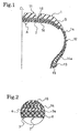
- the self-sealing tire of the present invention comprises a pneumatic tire 1 and a puncture sealing layer 2 attached to an entire tire inner wall surface 1X from one shoulder portion S to the other shoulder portion S of the pneumatic tire 1.
- the pneumatic tire 1 has a crown portion 11, right and left sidewall portions 12, and right and left bead portions 13.
- a carcass layer 14 Provided between the right and left bead portions 13 are a carcass layer 14, both end portions 14a of which are turned axially outwardly around a bead core 15 embedded in each of the bead portions 13.
- a plurality of belt layers 16 are disposed radially outwardly of the carcass layer 14 in the crown portion 11.
- the tire centerline is designated by CL
- the puncture sealing layer 2 is formed in an annular shape and, as shown in FIG. 2, comprises a sponge layer 3 impregnated with a high viscosity adhesive X as sealing material so that it is not exposed on the radially inner surface side of the sponge layer but is exposed on the radially outer surface side thereof, and an bonding layer 4, made of an adhesive, which is provide on the radially outer surface 3a of the sponge layer 3 and bonds to the tire inner wall surface 1X.
- the adhesive used for the bonding layer 4 is composed of the same high viscosity adherent composition as the adhesive X impregnated into the sponge layer 3, and the bonding layer 4 is integrally formed on the radially outer surface 3a of the sponge layer 3.
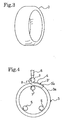
- the sponge layer 3 which is annularly shaped and is elastic, is arranged such that the peripheral length (outer circumference length) Ls of the radially outer surface of the sponge layer 3 prior to attachment of the puncture sealing layer 2 to the pneumatic tire 1 (see FIG. 3) is longer than the tire inner circumference length Lt of the tire inner wall surface 1X between the shoulder portions S to which the puncture sealing layer 2 is attached, the sponge layer 3 being attached in a radially inwardly compressed state, thereby press attaching the puncture sealing layer 2 to the tire inner wall surface 1X by a restoring force of the sponge layer 3 acting radially outwards.
- the self-sealing tire having the aforementioned puncture sealing layer 2 is manufactured as follows.
- adhesive X discharged from a discharge port 6 of an adhesive extruder is consecutively press attached by means of a pair of rollers 7, 7 onto the radially outer surface 3a of the annular preformed sponge layer 3 rotated by rollers 5, 5 so as to round the radially outer surface 3a.
- the adhesive X is impregnated into the sponge layer 3 from the radially outer surface 3a during this process, thereby forming an adhesive impregnated sponge layer 3' which has the adhesive X not exposed on the radially inner surface side, but exposed on the radially outer surface side thereof, and simultaneously forming the bonding layer 4 made of the adhesive X on the radially outer surface 3'a of the adhesive impregnated sponge layer 3' (the radially outer surface 3a of the sponge layer 3) to form the puncture sealing layer 2.
- the obtained puncture sealing layer 2 is compressed and introduced inside the pneumatic tire 1, and is then decompressed.
- the puncture sealing layer 2 is pressed to the tire inner wall surface 1X with the bonding layer 4 being stuck closely thereto by a restoring force of the sponge layer 3 trying to restitute to its original size, whereby the puncture sealing layer 2 is press attached and tightly bonded to the tire inner wall surface 1X without press attaching the puncture sealing layer 2 thereto by applying a high compression force from the outside.
- the adhesive X is impregnated so as to be exposed on the radially outer surface side of the sponge layer 3 and not to be exposed on the radially inner surface side thereof, dust and foreign object are prevented from sticking during transporting, stocking and the like, thus not deteriorating the appearance. Also, the adhesive does not stick to a hand of the operator and equipment during handling of the tire, thereby improving the handling performance.
- the puncture sealing layer 2 can be easily and tightly bonded to the tire inner wall surface 1X without press attachment operation by application of a high compression force from the outside by means of press rollers or the like. Accordingly, a good workability can be obtained.
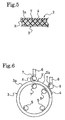
- FIG. 5 shows another puncture sealing layer used for the self-sealing tire of the present invention.
- This puncture sealing layer 2 has a bonding layer 4 which is composed of a high viscosity adhesive Y made of an adherent composition different from the adhesive X and which has a high viscosity sealing capacity.
- Such a puncture sealing layer 2 is formed as follows. As shown in FIG. 6, adhesive X discharged from a discharge port 6 of a first adhesive extruder is consecutively press attached by means of a pair of rollers 7, 7 onto an radially outer surface 3a of an annular sponge layer 3 rotated by rollers 5, 5. The adhesive X is impregnated into the sponge layer 3 from the radially outer surface 3a, thereby sequentially forming an adhesive impregnated sponge layer 3' such that the adhesive X is not exposed to the radially inner surface side but exposed to the radially outer surface side thereof.
- adhesive Y discharged from a discharge port 8 of a second adhesive extruder is consecutively press attached onto the radially outer surface 3a' of the adhesive impregnated sponge layer 3' by means of a pair of rotating rollers 9, 9.
- the bonding layer 4 is sequentially formed on the radially outer surface 3a'.
- the puncture sealing layer 2 is formed by applying the adhesives X, Y so that they round the sponge layer 3.
- the puncture sealing layer 2 formed as mentioned above is bonded to the tire inner wall surface 1 X in a similar manner to that described above.
- the puncture sealing layer 2 shown in FIG. 5 may be formed by formation of the bonding layer 4 on the tire inner wall surface 1X beforehand, and by adhesion of an adhesive impregnated sponge layer 3' to the bonding layer 4. It should be appreciated that the bonding layer 4 formed on the tire inner wall surface may be formed using the adhesive X.
- a relationship between the outer circumference length Ls of the sponge layer 3 and the tire inner circumference length Lt of the tire inner wall surface 1X be set to 1.1 Lt ⁇ Ls ⁇ 1.3 Lt on the tire centerline CL.
- the outer circumference length Ls of the sponge layer 3 is less than 1.1 Lt, it is difficult to firmly adhere the puncture sealing layer 2 to the tire inner wall surface 1X by the recovery force of the sponge layer 3, deteriorating the puncture sealing ability. If it is larger than 1.3Lt, the circumference length of the sponge layer 3 is so long that the sponge layer 3 is partially bent radially inward, creating an insufficiently adhered part, and when a puncture happens in the part by a nail or the like, the part peels off from the tire inner wall face 1X, causing the deterioration of a puncture sealing ability.
- the thickness of the sponge layer 3 prior to attachment of the puncture sealing layer and the impregnation depth of the adhesive X with which the sponge layer 3 is impregnated may conveniently be selected according to the size of a pneumatic tire to be attached. From the viewpoint of prevention of excessive increase in tire weight, and of a good sealing ability, it is preferable to set the thickness of the sponge layer 3 to be 5 to 15 mm, and the impregnation depth of the adhesive X to be 4 to 12 mm.
- the impregnation amount of adhesive X is preferably 0.1 to 0.5 g/cm 3 .
- Material composing the aforementioned sponge layer 3 may preferably include a rubber having a continuous bubble into which the adhesive X can be impregnated, and a foam resin formed of polyurethane, nylon or the like. It is desirable to employ a continuous bubble type ether system polyurethane foam.
- an elastomer blended with an amorphous polyolefin, paraffin oil, or tackifier such as petroleum resin or low molecular weigh oligomer which is, for example, liquid polybutene may preferably be used.
- the elastomer may preferably be, for instance, at least one type of elastomer selected from a group of butyl rubber, polyisobutylene, natural rubber, isoprene rubber and polybutene in order to enhance the air impermeability of the tire in a normal use state with no puncture.
- the aforementioned elastomer blended with tackifier such as petroleum resin or low molecular weigh oligomer which is, for example, liquid polybutene may be used as the adhesive.
- the adherent composition used for the adhesive Y may be one as used in the case of forming the bonding layer 4 with the adhesive X.
- An appropriate crosslinking agent or vulcanizing agent may be blended with the adhesive X, Y in order to provide heat resistance for the adhesive.
- p- quinonedioxime or the like may be blended.
- the adhesives X, Y be made of an adherent composition not containing solvent, and that the viscosity thereof is adjusted to be about 10000Pa ⁇ s.
- Tires of the present invention and of the comparison were manufactured, having a tire size of 205/65R15 and a tire construction shown in FIG. 1, the tire of the present invention having a puncture sealing layer which was press attached to the tire inner wall surface by a restoring force of the sponge layer with its outer circumference length Ls longer than the tire inner circumference length Lt of the tire inner wall surface, and the comparative tire having a puncture sealing layer which was attached to the tire inner wall surface with the sponge layer thereof having an outer circumference length Ls equal to the tire inner circumference length Lt of the tire inner wall surface.
- the outer circumference length Ls of the sponge layer of the present invention at a position corresponding to that of the tire centerline prior to attachment was 1.2 times longer than the tire inner circumference length Lt of the tire inner wall surface on the tire centerline.
- Each sponge layer used for the present invention and comparative tires was composed of a continuous bubble type ether system polyurethane foam, and a composition having butyl rubber and liquid polybutene as main components was used for the adhesive.
- each sponge layer used for the present invention and comparative tires was 10 mm and the adhesive impregnation depth was 8 mm.
- test tires were each attached to a rim having a size of 15 x 6JJ, with the tire air pressure being set to 200 kPa, and a puncture sealing ability evaluation test was performed under the following measurement method, thereby obtaining the results shown in Table 1.
- the present invention tire having a puncture sealing layer which was press attached to the tire inner wall surface by a restoring force of the sponge layer can demonstrate a good puncture sealing ability.
- Test tires 1 to 5 were respectively manufactured, having the same tire size and construction as in Example 1, the test tires each having a puncture sealing layer disposed on the tire inner wall surface, the outer circumference length Ls of each sponge layer at a position corresponding to that of the tire centerline prior to attachment with respect to the tire inner circumference length Lt of the tire inner wall surface at a position of the tire centerline being changed as shown in Table 2.
- Each sponge layer used for the test tires was composed of a continuous bubble type ether system polyurethane foam, and a composition having butyl rubber and liquid polybutene as main components was used for the adhesive.
- the thicknesses t of the sponge layers and the adhesive impregnation depths h were shown in Table 2, respectively.
- the outer circumference length Ls of the sponge layer may be 1.1 to 1.3 times longer than the tire inner circumference length Lt of the tire inner wall surface.
- the present invention can prevent the adhesive from flowing to the center side of the crown portion by a centrifugal force generated during traveling of a vehicle, since the adhesive used for the puncture sealing layer is impregnated into the sponge layer.
- the adhesive is not exposed on the radially inner surface side of the sponge layer, but is exposed on the radially outer surface side thereof, the deterioration of appearance due to sticking of dust and foreign object during transporting, stocking and the like does not occur, and a good handling performance can be obtained.
- the puncture sealing layer can be easily and tightly bonded to the tire inner wall surface without press attachment operation by application of a high compression force from the outside by means of press rollers or the like, thereby attaining a good workability.
- the present invention having the aforementioned excellent effects can be used very effectively for a self-sealing tire having a self-sealing function of sealing a puncture to prevent air from leaking outside the tire when it blows out by a nail or others penetrating its crown portion during traveling of a vehicle.
Landscapes
- Engineering & Computer Science (AREA)
- Mechanical Engineering (AREA)
- Tires In General (AREA)
- Tyre Moulding (AREA)
Abstract
Description
| Present invention tire | Comparative tire | |
| Puncture sealing ability | ○ | × |
| Test tire 1 | | | | | |
| Outer circumference length Ls | 1.05Lt | 1.10Lt | 1.20Lt | 1.30Lt | 1.40Lt |
| Thickness t (mm) | 10 | 10 | 10 | 10 | 10 |
| Depth h (mm) | 8 | 6 | 8 | 8 | 8 |
| Puncture sealing ability | × | ○ | ○ | ○ | × |
Claims (13)
- A self-sealing tire having a pneumatic tire and a puncture sealing layer disposed over a whole tire inner wall surface from one shoulder portion to the other shoulder portion of the pneumatic tire,
wherein the puncture sealing layer comprises an annular sponge layer which is impregnated with an adhesive so as to be exposed on a radially outer surface side thereof, and a bonding layer of an adhesive which is provided on a radially outer surface of the sponge layer and is adhered to the tire inner wall surface, the sponge layer being provided in a compressed state, the puncture sealing layer being press attached to the tire inner wall surface by a recovery force of the compressed sponge layer. - The self-sealing tire of claim 1, wherein a relationship between an outer circumference length Ls of the sponge layer at a position corresponding to that of the tire centerline of the pneumatic tire prior to attachment of the puncture sealing layer and a tire inner circumference length Lt of the tire inner wall surface at a position of the tire centerline is set to 1.1 Lt ≦Ls≦1.3 Lt.
- The self-sealing tire of claim 1 or 2, wherein the bonding layer is made of the same adherent composition as the adhesive with which the sponge layer is impregnated.
- The self-sealing tire of claim 3, wherein said bonding layer is integrally formed on the radially outer surface of the sponge layer.
- The self-sealing tire of claim 1, 2, 3 or 4, wherein the thickness of the sponge layer prior to attachment of the puncture sealing layer is 5 to 15 mm.
- The self-sealing tire of claim 5, wherein the impregnation depth of the adhesive which is impregnated into the sponge layer prior to attachment of the puncture sealing layer is 4 to 12 mm.
- The self-sealing tire of any one of claims 1 to 6, wherein the adhesives are made of an adherent composition not containing solvent.
- A method of manufacturing a self-sealing tire having a pneumatic tire and a puncture sealing layer disposed over a whole tire inner wall surface from one shoulder portion to the other shoulder portion of the pneumatic tire, comprising the steps of:impregnating an annular sponge layer with an adhesive from a radially outer surface side thereof to form an adhesive impregnated sponge layer so that the adhesive is exposed on the radially outer surface side;forming a bonding layer made of an adhesive on a radially outer surface of the adhesive impregnated sponge layer to form a puncture sealing layer; andpress attaching the puncture sealing layer onto the tire inner wall surface via the bonding layer by a recovery force of the sponge layer which has compressed.
- The self-sealing tire manufacturing method of claim 8, wherein a relationship between an outer circumference length Ls of the sponge layer at a position corresponding to that of the tire centerline of the pneumatic tire prior to attachment of the puncture sealing layer and a tire inner circumference length Lt of the tire inner wall surface at a position of the tire centerline is set to 1.1 Lt ≦ Ls≦1.3 Lt.
- The self-sealing tire manufacturing method of claim 8 or 9, wherein the adhesives are made of an adherent composition not containing solvent.
- A method of manufacturing a self-sealing tire having a pneumatic tire and a puncture sealing layer disposed over a whole tire inner wall surface from one shoulder portion to the other shoulder portion of the pneumatic tire, comprising the steps of:impregnating an annular sponge layer with an adhesive from a radially outer surface side thereof to form an adhesive impregnated sponge layer so that the adhesive is exposed on the radially outer surface side, and to simultaneously form a bonding layer made of the adhesive on a radially outer surface of the adhesive impregnated sponge layer integrally therewith, thereby forming a puncture sealing layer; andpress attaching the puncture sealing layer onto the tire inner wall surface via the bonding layer by a recovery force of the sponge layer which has compressed.
- The self-sealing tire manufacturing method of claim 11, wherein a relationship between an outer circumference length Ls of the sponge layer at a position corresponding to that of the tire centerline of the pneumatic tire prior to attachment of the puncture sealing layer and a tire inner circumference length Lt of the tire inner wall surface at a position of the tire centerline is set to 1.1 Lt ≦ Ls≦1.3 Lt.
- The self-sealing tire manufacturing method of claim 11 or 12, wherein the adhesive is made of an adherent composition not containing solvent.
Applications Claiming Priority (3)
| Application Number | Priority Date | Filing Date | Title |
|---|---|---|---|
| JP2002063320 | 2002-03-08 | ||
| JP2002063320 | 2002-03-08 | ||
| PCT/JP2002/010843 WO2003076214A1 (en) | 2002-03-08 | 2002-10-18 | Self-seal tire and its producing method |
Publications (3)
| Publication Number | Publication Date |
|---|---|
| EP1484199A1 true EP1484199A1 (en) | 2004-12-08 |
| EP1484199A4 EP1484199A4 (en) | 2006-06-07 |
| EP1484199B1 EP1484199B1 (en) | 2008-08-06 |
Family
ID=27800187
Family Applications (1)
| Application Number | Title | Priority Date | Filing Date |
|---|---|---|---|
| EP02775373A Expired - Lifetime EP1484199B1 (en) | 2002-03-08 | 2002-10-18 | Method of manufacturing a self-sealing tire |
Country Status (7)
| Country | Link |
|---|---|
| US (1) | US7195683B2 (en) |
| EP (1) | EP1484199B1 (en) |
| KR (1) | KR100985705B1 (en) |
| CN (1) | CN1299922C (en) |
| CA (1) | CA2466763C (en) |
| DE (1) | DE60228135D1 (en) |
| WO (1) | WO2003076214A1 (en) |
Cited By (2)
| Publication number | Priority date | Publication date | Assignee | Title |
|---|---|---|---|---|
| EP1904291A1 (en) * | 2005-07-15 | 2008-04-02 | Prospective Concepts AG | Self-healing membrane |
| EP3085523A1 (en) | 2015-04-24 | 2016-10-26 | Nokian Renkaat Oyj | A method for manufacturing a sealant layer to a pneumatic tire and a pneumatic tire |
Families Citing this family (12)
| Publication number | Priority date | Publication date | Assignee | Title |
|---|---|---|---|---|
| JP4491564B2 (en) * | 2005-10-24 | 2010-06-30 | 横浜ゴム株式会社 | Pneumatic tire |
| US7694707B2 (en) | 2005-12-20 | 2010-04-13 | The Goodyear Tire & Rubber Company | Tire with integral foamed noise damper |
| FR2910382B1 (en) * | 2006-12-22 | 2009-03-06 | Michelin Soc Tech | PNEUMATIC WITH SELF-SWITCHING LAYER |
| FR2915428B1 (en) * | 2007-04-26 | 2011-04-29 | Michelin Soc Tech | PNEUMATIC WITH REDUCED BEARING NOISE |
| US8617333B2 (en) | 2007-09-20 | 2013-12-31 | The Goodyear Tire & Rubber Company | Pneumatic tire having built-in sealant layer and preparation thereof |
| US8316903B2 (en) | 2007-10-01 | 2012-11-27 | The Goodyear Tire & Rubber Company | Pneumatic tire having built-in sealant layer and preparation thereof |
| FR2939145B1 (en) * | 2008-12-03 | 2010-12-31 | Soc Tech Michelin | PNEUMATIC OBJECT COMPRISING A SELF-SEALING AND GAS-SEALED LAYER BASED ON THERMOPLASTIC ELASTOMER AND EXTENSION OIL |
| US11267297B2 (en) | 2014-01-30 | 2022-03-08 | Sumitomo Rubber Industries, Ltd. | Sealant tire |
| CN104309414B (en) * | 2014-09-30 | 2017-02-01 | 杭州绿奇科技有限公司 | Chip mounting method for puncture-proof tire, chip mounter and using method of chip mounter |
| EP3385096A4 (en) * | 2015-11-30 | 2019-01-02 | Bridgestone Corporation | Pneumatic tire |
| DE102016211111A1 (en) * | 2016-06-22 | 2017-12-28 | Continental Reifen Deutschland Gmbh | Self-sealing pneumatic vehicle tire and method for its manufacture |
| EP3793846B1 (en) | 2018-05-15 | 2025-05-28 | Bridgestone Americas Tire Operations, LLC | Tire with multi-layer insert |
Family Cites Families (17)
| Publication number | Priority date | Publication date | Assignee | Title |
|---|---|---|---|---|
| JPS5291903U (en) * | 1975-12-29 | 1977-07-09 | ||
| SE400131B (en) | 1976-01-21 | 1978-03-13 | Asea Ab | DEVICE FOR CONTROL EQUIPMENT FOR PROCESSING PATHS |
| JPS5615045Y2 (en) * | 1976-10-05 | 1981-04-09 | ||
| JPS5350905A (en) | 1976-10-20 | 1978-05-09 | Fujitsu Ltd | Start control system |
| JPS546206A (en) * | 1977-06-14 | 1979-01-18 | Bridgestone Corp | Pneumatic tire with puncture preventive layer |
| US4262719A (en) * | 1979-06-25 | 1981-04-21 | Harold Harry Vischer | Tire liner and method of preparation |
| GB2146959B (en) * | 1983-09-28 | 1987-04-29 | Goodyear Tire & Rubber | Self sealing pneumatic tire |
| US4919183A (en) * | 1983-09-28 | 1990-04-24 | The Goodyear Tire & Rubber Company | Self sealing pneumatic tire |
| US4664168A (en) * | 1985-01-22 | 1987-05-12 | The Uniroyal Goodrich Tire Company | Self-sealing tire with edge strips for tire sealant |
| US4913209A (en) * | 1985-01-22 | 1990-04-03 | The Uniroyal Goodrich Tire Company | Sealant product, laminate thereof, and pneumatic tire constructed therewith |
| AU1347888A (en) * | 1987-02-24 | 1988-09-26 | Emanuel Nunes Silva | Impervious tyre or container for holding a fluid |
| US5099900A (en) * | 1989-07-31 | 1992-03-31 | Gomberg Edward N | Self-healing tire system having an inner tube and a puncture sealant layer |
| JP2895953B2 (en) * | 1990-11-13 | 1999-05-31 | 住友ゴム工業株式会社 | Pneumatic tire |
| CN1103033A (en) * | 1994-05-10 | 1995-05-31 | 成都市青羊区长城高新技术研究所 | Inner tube free rubber tyre capable of automatic stopping leakage and inflating |
| JP4371472B2 (en) * | 1999-07-05 | 2009-11-25 | 横浜ゴム株式会社 | Self-sealing tire and manufacturing method thereof |
| DE10138603A1 (en) * | 2000-08-09 | 2002-02-28 | Yokohama Rubber Co Ltd | Pneumatic tyres for motor vehicles, comprises pore-containing layer of adhesive compound attached to inside of tyre as puncture-resistant layer |
| WO2002085649A1 (en) * | 2001-04-20 | 2002-10-31 | The Yokohama Rubber Co., Ltd. | Self-seal tire and method of manufacturing the tire |
-
2002
- 2002-10-18 CA CA2466763A patent/CA2466763C/en not_active Expired - Fee Related
- 2002-10-18 CN CNB028224396A patent/CN1299922C/en not_active Expired - Fee Related
- 2002-10-18 KR KR1020047006170A patent/KR100985705B1/en not_active Expired - Fee Related
- 2002-10-18 US US10/492,656 patent/US7195683B2/en not_active Expired - Fee Related
- 2002-10-18 WO PCT/JP2002/010843 patent/WO2003076214A1/en not_active Ceased
- 2002-10-18 EP EP02775373A patent/EP1484199B1/en not_active Expired - Lifetime
- 2002-10-18 DE DE60228135T patent/DE60228135D1/en not_active Expired - Lifetime
Cited By (2)
| Publication number | Priority date | Publication date | Assignee | Title |
|---|---|---|---|---|
| EP1904291A1 (en) * | 2005-07-15 | 2008-04-02 | Prospective Concepts AG | Self-healing membrane |
| EP3085523A1 (en) | 2015-04-24 | 2016-10-26 | Nokian Renkaat Oyj | A method for manufacturing a sealant layer to a pneumatic tire and a pneumatic tire |
Also Published As
| Publication number | Publication date |
|---|---|
| DE60228135D1 (en) | 2008-09-18 |
| WO2003076214A1 (en) | 2003-09-18 |
| KR20040088023A (en) | 2004-10-15 |
| CA2466763A1 (en) | 2003-09-18 |
| CN1299922C (en) | 2007-02-14 |
| US7195683B2 (en) | 2007-03-27 |
| CN1585702A (en) | 2005-02-23 |
| EP1484199B1 (en) | 2008-08-06 |
| KR100985705B1 (en) | 2010-10-06 |
| US20040256042A1 (en) | 2004-12-23 |
| CA2466763C (en) | 2011-04-05 |
| EP1484199A4 (en) | 2006-06-07 |
Similar Documents
| Publication | Publication Date | Title |
|---|---|---|
| EP1378379B1 (en) | Self-seal tire and method of producing the same | |
| US7195683B2 (en) | Self-seal tire and its producing method | |
| US4919183A (en) | Self sealing pneumatic tire | |
| KR102089270B1 (en) | Vehicle pneumatic tire | |
| EP2335911B1 (en) | Pneumatic tire with built-in innermost adhesive layer and post cure applied sealant | |
| EP2165824B1 (en) | Film to keep tire surface clean and simultaneously prime for better adheson of balance pad | |
| JPH01208207A (en) | Pneumatic tire | |
| EP1393932A1 (en) | Pneumatic tire and method of producing the same | |
| JP3837375B2 (en) | Self-sealing tire manufacturing method | |
| AU677169B2 (en) | Tubeless tyre beads and methods for manufacturing same | |
| EP0021255B1 (en) | Tire liner and method of preparation | |
| EP0893236A1 (en) | Self-sealing tyre and method of making the same | |
| CA1220703A (en) | Self sealing pneumatic tire | |
| US7040364B2 (en) | Pneumatic tire | |
| WO2019050030A1 (en) | Pneumatic tire and method for producing same | |
| JP3567431B2 (en) | Tubeless tire and method of manufacturing the same | |
| JP4615764B2 (en) | Pneumatic tire | |
| JP7709110B1 (en) | Pneumatic tire and manufacturing method thereof | |
| WO2002085649A1 (en) | Self-seal tire and method of manufacturing the tire | |
| WO2019050029A1 (en) | Pneumatic tire and method for producing same | |
| JP2004262274A (en) | Pneumatic tire and method of manufacturing the same | |
| CN121986029A (en) | Pneumatic tires and their manufacturing methods | |
| JPS6335412B2 (en) |
Legal Events
| Date | Code | Title | Description |
|---|---|---|---|
| PUAI | Public reference made under article 153(3) epc to a published international application that has entered the european phase |
Free format text: ORIGINAL CODE: 0009012 |
|
| 17P | Request for examination filed |
Effective date: 20040518 |
|
| AK | Designated contracting states |
Kind code of ref document: A1 Designated state(s): DE FR GB |
|
| AX | Request for extension of the european patent |
Extension state: AL LT LV MK RO SI |
|
| A4 | Supplementary search report drawn up and despatched |
Effective date: 20060503 |
|
| 17Q | First examination report despatched |
Effective date: 20071004 |
|
| GRAP | Despatch of communication of intention to grant a patent |
Free format text: ORIGINAL CODE: EPIDOSNIGR1 |
|
| RTI1 | Title (correction) |
Free format text: METHOD OF MANUFACTURING A SELF-SEALING TIRE |
|
| GRAS | Grant fee paid |
Free format text: ORIGINAL CODE: EPIDOSNIGR3 |
|
| GRAA | (expected) grant |
Free format text: ORIGINAL CODE: 0009210 |
|
| AK | Designated contracting states |
Kind code of ref document: B1 Designated state(s): DE FR GB |
|
| REG | Reference to a national code |
Ref country code: GB Ref legal event code: FG4D |
|
| REF | Corresponds to: |
Ref document number: 60228135 Country of ref document: DE Date of ref document: 20080918 Kind code of ref document: P |
|
| PLBE | No opposition filed within time limit |
Free format text: ORIGINAL CODE: 0009261 |
|
| STAA | Information on the status of an ep patent application or granted ep patent |
Free format text: STATUS: NO OPPOSITION FILED WITHIN TIME LIMIT |
|
| PGFP | Annual fee paid to national office [announced via postgrant information from national office to epo] |
Ref country code: GB Payment date: 20081107 Year of fee payment: 7 |
|
| 26N | No opposition filed |
Effective date: 20090507 |
|
| PGFP | Annual fee paid to national office [announced via postgrant information from national office to epo] |
Ref country code: DE Payment date: 20091015 Year of fee payment: 8 |
|
| PGFP | Annual fee paid to national office [announced via postgrant information from national office to epo] |
Ref country code: FR Payment date: 20091029 Year of fee payment: 8 |
|
| PG25 | Lapsed in a contracting state [announced via postgrant information from national office to epo] |
Ref country code: GB Free format text: LAPSE BECAUSE OF NON-PAYMENT OF DUE FEES Effective date: 20091018 |
|
| PG25 | Lapsed in a contracting state [announced via postgrant information from national office to epo] |
Ref country code: FR Free format text: LAPSE BECAUSE OF NON-PAYMENT OF DUE FEES Effective date: 20101102 |
|
| REG | Reference to a national code |
Ref country code: FR Ref legal event code: ST Effective date: 20110630 |
|
| REG | Reference to a national code |
Ref country code: DE Ref legal event code: R119 Ref document number: 60228135 Country of ref document: DE Effective date: 20110502 |
|
| PG25 | Lapsed in a contracting state [announced via postgrant information from national office to epo] |
Ref country code: DE Free format text: LAPSE BECAUSE OF NON-PAYMENT OF DUE FEES Effective date: 20110502 |