EP1484100A1 - Honeycomb structure, method of manufacturing the structure, and exhaust emission control system - Google Patents
Honeycomb structure, method of manufacturing the structure, and exhaust emission control system Download PDFInfo
- Publication number
- EP1484100A1 EP1484100A1 EP03744023A EP03744023A EP1484100A1 EP 1484100 A1 EP1484100 A1 EP 1484100A1 EP 03744023 A EP03744023 A EP 03744023A EP 03744023 A EP03744023 A EP 03744023A EP 1484100 A1 EP1484100 A1 EP 1484100A1
- Authority
- EP
- European Patent Office
- Prior art keywords
- honeycomb structure
- wall
- reinforced part
- range
- axial direction
- Prior art date
- Legal status (The legal status is an assumption and is not a legal conclusion. Google has not performed a legal analysis and makes no representation as to the accuracy of the status listed.)
- Withdrawn
Links
Images


Classifications
-
- C—CHEMISTRY; METALLURGY
- C04—CEMENTS; CONCRETE; ARTIFICIAL STONE; CERAMICS; REFRACTORIES
- C04B—LIME, MAGNESIA; SLAG; CEMENTS; COMPOSITIONS THEREOF, e.g. MORTARS, CONCRETE OR LIKE BUILDING MATERIALS; ARTIFICIAL STONE; CERAMICS; REFRACTORIES; TREATMENT OF NATURAL STONE
- C04B38/00—Porous mortars, concrete, artificial stone or ceramic ware; Preparation thereof
- C04B38/0006—Honeycomb structures
- C04B38/0009—Honeycomb structures characterised by features relating to the cell walls, e.g. wall thickness or distribution of pores in the walls
-
- B—PERFORMING OPERATIONS; TRANSPORTING
- B01—PHYSICAL OR CHEMICAL PROCESSES OR APPARATUS IN GENERAL
- B01D—SEPARATION
- B01D46/00—Filters or filtering processes specially modified for separating dispersed particles from gases or vapours
- B01D46/0001—Making filtering elements
-
- B—PERFORMING OPERATIONS; TRANSPORTING
- B01—PHYSICAL OR CHEMICAL PROCESSES OR APPARATUS IN GENERAL
- B01D—SEPARATION
- B01D46/00—Filters or filtering processes specially modified for separating dispersed particles from gases or vapours
- B01D46/24—Particle separators, e.g. dust precipitators, using rigid hollow filter bodies
- B01D46/2403—Particle separators, e.g. dust precipitators, using rigid hollow filter bodies characterised by the physical shape or structure of the filtering element
- B01D46/2418—Honeycomb filters
- B01D46/2425—Honeycomb filters characterized by parameters related to the physical properties of the honeycomb structure material
-
- B—PERFORMING OPERATIONS; TRANSPORTING
- B01—PHYSICAL OR CHEMICAL PROCESSES OR APPARATUS IN GENERAL
- B01D—SEPARATION
- B01D46/00—Filters or filtering processes specially modified for separating dispersed particles from gases or vapours
- B01D46/24—Particle separators, e.g. dust precipitators, using rigid hollow filter bodies
- B01D46/2403—Particle separators, e.g. dust precipitators, using rigid hollow filter bodies characterised by the physical shape or structure of the filtering element
- B01D46/2418—Honeycomb filters
- B01D46/2425—Honeycomb filters characterized by parameters related to the physical properties of the honeycomb structure material
- B01D46/2429—Honeycomb filters characterized by parameters related to the physical properties of the honeycomb structure material of the honeycomb walls or cells
-
- B—PERFORMING OPERATIONS; TRANSPORTING
- B01—PHYSICAL OR CHEMICAL PROCESSES OR APPARATUS IN GENERAL
- B01D—SEPARATION
- B01D46/00—Filters or filtering processes specially modified for separating dispersed particles from gases or vapours
- B01D46/24—Particle separators, e.g. dust precipitators, using rigid hollow filter bodies
- B01D46/2403—Particle separators, e.g. dust precipitators, using rigid hollow filter bodies characterised by the physical shape or structure of the filtering element
- B01D46/2418—Honeycomb filters
- B01D46/2425—Honeycomb filters characterized by parameters related to the physical properties of the honeycomb structure material
- B01D46/24491—Porosity
-
- B—PERFORMING OPERATIONS; TRANSPORTING
- B01—PHYSICAL OR CHEMICAL PROCESSES OR APPARATUS IN GENERAL
- B01D—SEPARATION
- B01D46/00—Filters or filtering processes specially modified for separating dispersed particles from gases or vapours
- B01D46/24—Particle separators, e.g. dust precipitators, using rigid hollow filter bodies
- B01D46/2403—Particle separators, e.g. dust precipitators, using rigid hollow filter bodies characterised by the physical shape or structure of the filtering element
- B01D46/2418—Honeycomb filters
- B01D46/2451—Honeycomb filters characterized by the geometrical structure, shape, pattern or configuration or parameters related to the geometry of the structure
- B01D46/2455—Honeycomb filters characterized by the geometrical structure, shape, pattern or configuration or parameters related to the geometry of the structure of the whole honeycomb or segments
-
- B—PERFORMING OPERATIONS; TRANSPORTING
- B01—PHYSICAL OR CHEMICAL PROCESSES OR APPARATUS IN GENERAL
- B01D—SEPARATION
- B01D46/00—Filters or filtering processes specially modified for separating dispersed particles from gases or vapours
- B01D46/24—Particle separators, e.g. dust precipitators, using rigid hollow filter bodies
- B01D46/2403—Particle separators, e.g. dust precipitators, using rigid hollow filter bodies characterised by the physical shape or structure of the filtering element
- B01D46/2418—Honeycomb filters
- B01D46/2451—Honeycomb filters characterized by the geometrical structure, shape, pattern or configuration or parameters related to the geometry of the structure
- B01D46/2459—Honeycomb filters characterized by the geometrical structure, shape, pattern or configuration or parameters related to the geometry of the structure of the plugs
-
- B—PERFORMING OPERATIONS; TRANSPORTING
- B01—PHYSICAL OR CHEMICAL PROCESSES OR APPARATUS IN GENERAL
- B01D—SEPARATION
- B01D46/00—Filters or filtering processes specially modified for separating dispersed particles from gases or vapours
- B01D46/24—Particle separators, e.g. dust precipitators, using rigid hollow filter bodies
- B01D46/2403—Particle separators, e.g. dust precipitators, using rigid hollow filter bodies characterised by the physical shape or structure of the filtering element
- B01D46/2418—Honeycomb filters
- B01D46/2451—Honeycomb filters characterized by the geometrical structure, shape, pattern or configuration or parameters related to the geometry of the structure
- B01D46/247—Honeycomb filters characterized by the geometrical structure, shape, pattern or configuration or parameters related to the geometry of the structure of the cells
-
- B—PERFORMING OPERATIONS; TRANSPORTING
- B01—PHYSICAL OR CHEMICAL PROCESSES OR APPARATUS IN GENERAL
- B01D—SEPARATION
- B01D46/00—Filters or filtering processes specially modified for separating dispersed particles from gases or vapours
- B01D46/24—Particle separators, e.g. dust precipitators, using rigid hollow filter bodies
- B01D46/2403—Particle separators, e.g. dust precipitators, using rigid hollow filter bodies characterised by the physical shape or structure of the filtering element
- B01D46/2418—Honeycomb filters
- B01D46/2451—Honeycomb filters characterized by the geometrical structure, shape, pattern or configuration or parameters related to the geometry of the structure
- B01D46/2482—Thickness, height, width, length or diameter
-
- B—PERFORMING OPERATIONS; TRANSPORTING
- B01—PHYSICAL OR CHEMICAL PROCESSES OR APPARATUS IN GENERAL
- B01D—SEPARATION
- B01D46/00—Filters or filtering processes specially modified for separating dispersed particles from gases or vapours
- B01D46/24—Particle separators, e.g. dust precipitators, using rigid hollow filter bodies
- B01D46/2403—Particle separators, e.g. dust precipitators, using rigid hollow filter bodies characterised by the physical shape or structure of the filtering element
- B01D46/2418—Honeycomb filters
- B01D46/2451—Honeycomb filters characterized by the geometrical structure, shape, pattern or configuration or parameters related to the geometry of the structure
- B01D46/2486—Honeycomb filters characterized by the geometrical structure, shape, pattern or configuration or parameters related to the geometry of the structure characterised by the shapes or configurations
- B01D46/249—Quadrangular e.g. square or diamond
-
- B—PERFORMING OPERATIONS; TRANSPORTING
- B01—PHYSICAL OR CHEMICAL PROCESSES OR APPARATUS IN GENERAL
- B01D—SEPARATION
- B01D53/00—Separation of gases or vapours; Recovering vapours of volatile solvents from gases; Chemical or biological purification of waste gases, e.g. engine exhaust gases, smoke, fumes, flue gases, aerosols
- B01D53/34—Chemical or biological purification of waste gases
- B01D53/92—Chemical or biological purification of waste gases of engine exhaust gases
- B01D53/94—Chemical or biological purification of waste gases of engine exhaust gases by catalytic processes
- B01D53/9445—Simultaneously removing carbon monoxide, hydrocarbons or nitrogen oxides making use of three-way catalysts [TWC] or four-way-catalysts [FWC]
- B01D53/9454—Simultaneously removing carbon monoxide, hydrocarbons or nitrogen oxides making use of three-way catalysts [TWC] or four-way-catalysts [FWC] characterised by a specific device
-
- F—MECHANICAL ENGINEERING; LIGHTING; HEATING; WEAPONS; BLASTING
- F01—MACHINES OR ENGINES IN GENERAL; ENGINE PLANTS IN GENERAL; STEAM ENGINES
- F01N—GAS-FLOW SILENCERS OR EXHAUST APPARATUS FOR MACHINES OR ENGINES IN GENERAL; GAS-FLOW SILENCERS OR EXHAUST APPARATUS FOR INTERNAL-COMBUSTION ENGINES
- F01N3/00—Exhaust or silencing apparatus having means for purifying, rendering innocuous, or otherwise treating exhaust
- F01N3/02—Exhaust or silencing apparatus having means for purifying, rendering innocuous, or otherwise treating exhaust for cooling, or for removing solid constituents of, exhaust
- F01N3/021—Exhaust or silencing apparatus having means for purifying, rendering innocuous, or otherwise treating exhaust for cooling, or for removing solid constituents of, exhaust by means of filters
- F01N3/0211—Arrangements for mounting filtering elements in housing, e.g. with means for compensating thermal expansion or vibration
-
- F—MECHANICAL ENGINEERING; LIGHTING; HEATING; WEAPONS; BLASTING
- F01—MACHINES OR ENGINES IN GENERAL; ENGINE PLANTS IN GENERAL; STEAM ENGINES
- F01N—GAS-FLOW SILENCERS OR EXHAUST APPARATUS FOR MACHINES OR ENGINES IN GENERAL; GAS-FLOW SILENCERS OR EXHAUST APPARATUS FOR INTERNAL-COMBUSTION ENGINES
- F01N3/00—Exhaust or silencing apparatus having means for purifying, rendering innocuous, or otherwise treating exhaust
- F01N3/02—Exhaust or silencing apparatus having means for purifying, rendering innocuous, or otherwise treating exhaust for cooling, or for removing solid constituents of, exhaust
- F01N3/021—Exhaust or silencing apparatus having means for purifying, rendering innocuous, or otherwise treating exhaust for cooling, or for removing solid constituents of, exhaust by means of filters
- F01N3/022—Exhaust or silencing apparatus having means for purifying, rendering innocuous, or otherwise treating exhaust for cooling, or for removing solid constituents of, exhaust by means of filters characterised by specially adapted filtering structure, e.g. honeycomb, mesh or fibrous
- F01N3/0222—Exhaust or silencing apparatus having means for purifying, rendering innocuous, or otherwise treating exhaust for cooling, or for removing solid constituents of, exhaust by means of filters characterised by specially adapted filtering structure, e.g. honeycomb, mesh or fibrous the structure being monolithic, e.g. honeycombs
-
- F—MECHANICAL ENGINEERING; LIGHTING; HEATING; WEAPONS; BLASTING
- F01—MACHINES OR ENGINES IN GENERAL; ENGINE PLANTS IN GENERAL; STEAM ENGINES
- F01N—GAS-FLOW SILENCERS OR EXHAUST APPARATUS FOR MACHINES OR ENGINES IN GENERAL; GAS-FLOW SILENCERS OR EXHAUST APPARATUS FOR INTERNAL-COMBUSTION ENGINES
- F01N3/00—Exhaust or silencing apparatus having means for purifying, rendering innocuous, or otherwise treating exhaust
- F01N3/02—Exhaust or silencing apparatus having means for purifying, rendering innocuous, or otherwise treating exhaust for cooling, or for removing solid constituents of, exhaust
- F01N3/021—Exhaust or silencing apparatus having means for purifying, rendering innocuous, or otherwise treating exhaust for cooling, or for removing solid constituents of, exhaust by means of filters
- F01N3/033—Exhaust or silencing apparatus having means for purifying, rendering innocuous, or otherwise treating exhaust for cooling, or for removing solid constituents of, exhaust by means of filters in combination with other devices
- F01N3/035—Exhaust or silencing apparatus having means for purifying, rendering innocuous, or otherwise treating exhaust for cooling, or for removing solid constituents of, exhaust by means of filters in combination with other devices with catalytic reactors
-
- B—PERFORMING OPERATIONS; TRANSPORTING
- B01—PHYSICAL OR CHEMICAL PROCESSES OR APPARATUS IN GENERAL
- B01D—SEPARATION
- B01D46/00—Filters or filtering processes specially modified for separating dispersed particles from gases or vapours
- B01D46/24—Particle separators, e.g. dust precipitators, using rigid hollow filter bodies
- B01D46/2403—Particle separators, e.g. dust precipitators, using rigid hollow filter bodies characterised by the physical shape or structure of the filtering element
- B01D46/2418—Honeycomb filters
- B01D46/2498—The honeycomb filter being defined by mathematical relationships
-
- C—CHEMISTRY; METALLURGY
- C04—CEMENTS; CONCRETE; ARTIFICIAL STONE; CERAMICS; REFRACTORIES
- C04B—LIME, MAGNESIA; SLAG; CEMENTS; COMPOSITIONS THEREOF, e.g. MORTARS, CONCRETE OR LIKE BUILDING MATERIALS; ARTIFICIAL STONE; CERAMICS; REFRACTORIES; TREATMENT OF NATURAL STONE
- C04B2111/00—Mortars, concrete or artificial stone or mixtures to prepare them, characterised by specific function, property or use
- C04B2111/00474—Uses not provided for elsewhere in C04B2111/00
- C04B2111/00793—Uses not provided for elsewhere in C04B2111/00 as filters or diaphragms
-
- C—CHEMISTRY; METALLURGY
- C04—CEMENTS; CONCRETE; ARTIFICIAL STONE; CERAMICS; REFRACTORIES
- C04B—LIME, MAGNESIA; SLAG; CEMENTS; COMPOSITIONS THEREOF, e.g. MORTARS, CONCRETE OR LIKE BUILDING MATERIALS; ARTIFICIAL STONE; CERAMICS; REFRACTORIES; TREATMENT OF NATURAL STONE
- C04B2111/00—Mortars, concrete or artificial stone or mixtures to prepare them, characterised by specific function, property or use
- C04B2111/00474—Uses not provided for elsewhere in C04B2111/00
- C04B2111/0081—Uses not provided for elsewhere in C04B2111/00 as catalysts or catalyst carriers
-
- F—MECHANICAL ENGINEERING; LIGHTING; HEATING; WEAPONS; BLASTING
- F01—MACHINES OR ENGINES IN GENERAL; ENGINE PLANTS IN GENERAL; STEAM ENGINES
- F01N—GAS-FLOW SILENCERS OR EXHAUST APPARATUS FOR MACHINES OR ENGINES IN GENERAL; GAS-FLOW SILENCERS OR EXHAUST APPARATUS FOR INTERNAL-COMBUSTION ENGINES
- F01N2330/00—Structure of catalyst support or particle filter
- F01N2330/06—Ceramic, e.g. monoliths
-
- Y—GENERAL TAGGING OF NEW TECHNOLOGICAL DEVELOPMENTS; GENERAL TAGGING OF CROSS-SECTIONAL TECHNOLOGIES SPANNING OVER SEVERAL SECTIONS OF THE IPC; TECHNICAL SUBJECTS COVERED BY FORMER USPC CROSS-REFERENCE ART COLLECTIONS [XRACs] AND DIGESTS
- Y02—TECHNOLOGIES OR APPLICATIONS FOR MITIGATION OR ADAPTATION AGAINST CLIMATE CHANGE
- Y02T—CLIMATE CHANGE MITIGATION TECHNOLOGIES RELATED TO TRANSPORTATION
- Y02T10/00—Road transport of goods or passengers
- Y02T10/10—Internal combustion engine [ICE] based vehicles
- Y02T10/12—Improving ICE efficiencies
-
- Y—GENERAL TAGGING OF NEW TECHNOLOGICAL DEVELOPMENTS; GENERAL TAGGING OF CROSS-SECTIONAL TECHNOLOGIES SPANNING OVER SEVERAL SECTIONS OF THE IPC; TECHNICAL SUBJECTS COVERED BY FORMER USPC CROSS-REFERENCE ART COLLECTIONS [XRACs] AND DIGESTS
- Y10—TECHNICAL SUBJECTS COVERED BY FORMER USPC
- Y10T—TECHNICAL SUBJECTS COVERED BY FORMER US CLASSIFICATION
- Y10T428/00—Stock material or miscellaneous articles
- Y10T428/24—Structurally defined web or sheet [e.g., overall dimension, etc.]
- Y10T428/24149—Honeycomb-like
Definitions
- the present invention relates to a honeycomb structure, a method of manufacturing the same and an exhaust emission control system comprising the same used in, for example, a filter for trapping fine particles present in an exhaust gas emitted from an internal combustion engine, a boiler or the like.
- the present invention relates to a honeycomb structure, a method of manufacturing the same and an exhaust emission control system comprising the same which is good in mechanical strength as well as low in pressure loss.
- the honeycomb structure for use in this purpose has a number of cells 3 partitioned from one another by partition walls 2.
- the cells extend through an X-axis direction.
- the honeycomb structure has a structure in which the cells 3 adjacent to each other are plugged in one end on an opposite side alternately so that end surfaces have checkered patterns.
- subject fluid flows in the cell 3 not plugged at inflow end face 42, that is, plugged at outflow end face 44, passes through the porous partition walls 2, and is discharged via the adjacent cells 3, that is, the cell 3 plugged at the inflow end face 42 and not plugged at outflow end face 44.
- the partition walls 2 act as a filter. For example, PM discharged from a diesel engine is trapped by the partition walls and deposited on the partition walls.
- the exhaust emission control system for an internal combustion engine that employs the filter of the aforementioned type as an emission control device suffers from pressure loss of exhaust gas. That is, pressure loss of exhaust gas occurs across the honeycomb structure, causing decrease in output of the internal combustion engine and deterioration in fuel consumption.
- pressure loss of exhaust gas occurs across the honeycomb structure, causing decrease in output of the internal combustion engine and deterioration in fuel consumption.
- increase in porosity of the honeycomb structure usually causes decrease in mechanical strength of the honeycomb structure. Therefore, there is a need for a honeycomb structure and an exhaust emission control system using the same which is low in pressure loss and good in strength.
- the present invention was made in consideration of the above circumstances, and it is an object of the present invention to provide a honeycomb structure which is good in mechanical strength as well as low in pressure loss, a method of manufacturing the same, and an exhaust emission control system comprising the honeycomb structure.
- the present inventors found that the weakest portion against the force from outside of the outer wall in the honeycomb structure lies in the direction of 45° with respect to the longitudinal direction of a partition wall about the sectional center in the cross section of the honeycomb structure. It was also found that when the honeycomb structure is held by a can (can body), in particular, cracking is likely to occur in that portion. It was also found that by reinforcing a certain range centered at a point in the direction of 45° on the outer wall, a honeycomb structure causing less elevation of pressure loss and having improved strength is obtained.
- the present invention is based on the above findings, and first provides a honeycomb structure (first aspect) including an outer wall; partition walls disposed inside the outer wall; and a plurality of cells partitioned from one another by the partition walls, extending in the axial direction, each cell having a generally rectangular cross-section shape in the direction perpendicular to the axial direction, characterized in that the honeycomb structure has a reinforced part in a part of the outer wall, and the reinforced part in the cross section perpendicular to the axial direction of the honeycomb structure lies at least in the range from the point located at 40° on the outer wall to the point located at 50° on the outer wall and within the range from the point located at 30° on the outer wall to the point located at 60° on the outer wall, with respect to the longitudinal direction of the partition wall about a sectional center of the honeycomb structure; and a mean thickness of the reinforced part in the perpendicular cross-section in the direction of the sectional center is in the range of 1 to 10 mm.
- the reinforced part is preferably formed by plugging of the cell.
- a sum of length of the reinforced part in the axial direction of the honeycomb structure is preferably 1/3 or more relative to whole length of the honeycomb structure in the axial direction.
- the partition walls and the outer walls preferably contain ceramics as a main component. It is more preferable that a main component of the ceramics is one or more kinds selected from the group consisting of alumina, mullite, lithium aluminum silicate, cordierite, silicon carbide and silicon nitride.
- a porosity of the partition wall is preferably 50% or more.
- the present invention can preferably be applied to the honeycomb structure having compressive strength in the axial direction in a range of 0.5 to 10 MPa. It is preferable that opening ends of predetermined cells are plugged at one end face and opening ends of a predetermined cells of the remaining cells are plugged at the other end face. It is also preferable that a catalyst having a promotion capability of burning diesel particulate matter.
- the present invention provides an exhaust emission control system (second aspect) including: an internal combustion engine; an exhaust pipe for discharging an exhaust gas from the internal combustion engine; and an emission control apparatus, connected to the exhaust pipe, for cleaning the exhaust gas, characterized in that the emission control apparatus includes at least one honeycomb structure as described above, and further includes a cushioning material disposed on the outer circumference of the honeycomb structure and a can holding at least therein the honeycomb structure via the cushioning material.
- the present invention provides a method of manufacturing a honeycomb structure (third aspect) having an outer wall; partition walls disposed inside the outer wall; a plurality of cells partitioned from one another by the partition walls, extending in the axial direction, each cell having a generally rectangular cross-section shape in the direction perpendicular to the axial direction; and a reinforced part provided in a part of the outer wall, the method comprising the steps of: forming a formed body of the honeycomb structure; firing the formed body to form a fired body; and reinforcing for formation of the reinforced part, characterized in that the reinforcing step is to form the reinforced part such that it lies at least in the range from the point located at 40° on the outer wall to the point located at 50° on the outer wall and within the range from the point located at 30° on the outer wall to the point located at 60° on the outer wall, with respect to the longitudinal direction of the partition wall about a sectional center of the honeycomb structure; and a mean thickness of the reinforced part in the perpendicular cross-
- the reinforcing step is plugging opening ends of at least two adjacent cells located within the predetermined range on the same end face; preferably, the reinforcing step includes cutting at least part of the fired body in the predetermined range and disposing a reinforcing material in the cut part; and preferably, the cutting step includes cutting the outer circumference of the fired body and cutting at least part of the partition wall within the predetermined range.
- a honeycomb structure which is the first aspect of the invention
- an exhaust emission control system which is the second aspect of the invention
- a method of manufacturing a honeycomb structure which is the third aspect of the invention.
- the present invention is not limited to the following embodiments.
- a section means a section perpendicular to the longitudinal direction of the cells, that is the X-axis direction of Fig. 1, unless especially mentioned.
- the term "axial direction" means the longitudinal direction of a cell (X-axis direction in Fig. 1).
- the honeycomb structure which is the first aspect of the present invention is a honeycomb structure 1 having an outer wall 7, partition walls 2a and 2b disposed inside the outer wall 7, and a plurality of cells 3a and 3b partitioned from one another by the partition walls 2a and 2b and extending in the axial direction, each having a generally rectangular cross section shape.
- the honeycomb structure of the present invention is used as a DPF, the structure as shown in Fig.
- FIG. 1(c) is employed in that opening ends of a predetermined number of cells 3a are plugged on one end face, while opening ends of the remaining predetermined number of cells 3b are plugged on the other end face (not shown) .
- this structure is not an essential feature of the invention.
- the black or gray mark in Figs. 1(a) to 1(c) and in the following drawings represents that the cell is plugged on that end face.
- a reinforced part 72 is formed on a part of the outer wall 7; and as shown in Fig. 2, the reinforced part lies, in the cross section of the honeycomb structure, at least in the range from a point 701 located at 40° on the outer wall 7 with respect to the longitudinal direction (Y direction) of the partition wall 2a about a sectional center 9 of the honeycomb structure 1 to a point 703 located at 50° on the outer wall 7 with respect to the longitudinal direction of the partition wall 2a about the sectional center 9 of the honeycomb structure 1, and lies in the range from a point 705 located at 30° on the outer wall 7 with respect to the longitudinal direction of the partition wall 2a about the sectional center 9 of the honeycomb structure 1 to a point 707 located at 60° on the outer wall 7 with respect to the longitudinal direction of the partition wall 2a about the sectional center 9 of the honeycomb structure 1; and a mean thickness t of the reinforced part 72 in the direction of the
- the poor strength of the outer wall at the point of 45° with respect to the partition wall about the sectional center may attribute to the fact that the cells adjacent to the outer wall have incomplete cross-section shapes, and the cell adjacent to the outer wall at 45° point has most incomplete cross-section shape. Therefore, as shown in Fig. 2, by reinforcing the outer wall in the range of at least ⁇ 5° around a point 709 which is located at 45° on the outer wall 7 with respect to the longitudinal direction of the partition wall 2a about the sectional center 9 of the honeycomb structure (range "a" in Fig. 2), it is possible to produce a honeycomb structure having increased strength.
- the effective area of the honeycomb structure is reduced so that the pressure loss increases.
- the term "sectional center” means the center of figure of the cross section of the honeycomb structure.
- the outer wall should have at least one reinforced part.
- the partition wall consists of the partition wall 2a parallel to one direction and the partition wall 2b perpendicular to the one direction. Accordingly, as shown in Fig. 1(b), the outer wall can be reinforced at four points at maximum, and preferably, the reinforced part is provided at all of these four points.
- the honeycomb structure has a cell having a generally rectangular cross-section shape.
- the term "generally rectangular shape" refers to the shape formed by the partition walls crossing with each other at four points on the cross section.
- each vertex formed by crossing partition walls may have a curvature.
- the partition walls intersect at right angles, and more preferably, they intersect at right angles so that the cross-section shape of each cell is substantially square.
- each partition wall is formed linearly from one point on the outer wall to the other one point on the outer wall.
- the reinforced part has a mean thickness in the direction of sectional center ranging from 1 to 10 mm, preferably from 2 to 5 mm. If the thickness is too small, the reinforcing effect is inadequate, while if the thickness is too large, the pressure loss increases too much extent to lead unfavorable result.
- the reinforced part is formed inside the outer wall as shown in Fig. 2. There is also the case that no boundary is formed between the outer wall and the partition wall by forming the outer wall and the reinforced part in integrated manner.
- the mean thickness of the reinforced part in the direction of sectional center means a difference between the mean thickness of the total of the outer wall and the reinforced part in the reinforced part and the mean thickness of the outer wall where the reinforced part is not formed.
- the embodiment that the reinforced part 72 is formed near either one or both of the end faces 42 and 44 is preferable from the view point of preventing edge end portions from being chipped when the honeycomb structure is inserted into a can, for example.
- the reinforced part of the embodiment as shown in Fig. 3 is formed, for example, by plugging the cells 3 lying in the above-mentioned range to be reinforced.
- the depth á in the axial direction of the reinforced part (longitudinal direction of cell) when the reinforced part is formed by plugging is preferably 2 mm or more because the depth smaller than this can not sufficiently provide reinforcing effect.
- the total depth of the reinforced part in the axial direction preferably the total depth of the reinforced part positioned at the same position viewed in the cross section, namely the sum of á 1 and á 2 in Fig. 4 is preferably 1/3 or more relative to the entire axial length of the honeycomb structure.
- the reinforced part may be provided from each end face to a predetermined depth as shown in Fig. 4, from either one end face to a predetermined depth, or in the center part of the axial direction. Combination of these is also applicable. Also it is a preferred from the view point of improving the reinforcing strength that the reinforced part is formed in the entire range from the end face 42 to the end face 44.
- the partition wall and the outer wall of the honeycomb structure is preferably formed primarily of ceramics, and examples of the ceramics include a variety of ceramics of oxides or non-oxides, concretely, alumina, mullite, lithium aluminum silicate, cordierite, silicon carbide, silicon nitride, spinel, silicon carbide/cordierite based composite material, silicon/silicon carbide based composite material, silicon nitride, aluminum titanium and the like.
- one or more than one selected from the group consisting of alumina, mullite, lithium aluminum silicate, cordierite, silicon carbide and silicon nitride is preferred from the view point of the strength, heat resistance and the like.
- the "main component” constitutes 50% by mass or more, preferably 70% by mass or more, further preferably 80% by mass or more of the honeycomb structure.
- the reinforced part may be formed of the same or different material from that of the outer wall, the main components are preferably the same material.
- the partition wall is preferably a porous material serving as a filter.
- the porosity is preferably 50% or more and more preferably, 60% or more.
- the porosity is preferably 75% or less.
- the first aspect of the present invention exerts more remarkable effect by being applied to the honeycomb structure in which axial compressive strength is poor.
- the range of axial compressive strength where the first aspect can be applied more effectively is from 0.5 to 10 MPa.
- the honeycomb structure according to the first aspect When the honeycomb structure according to the first aspect is used as a DPF, predetermined cells are plugged as described above.
- This plugging enables subject fluid to flow into the cell 3b which is open, for example, at one end face 42, pass through the porous partition walls 2, and be discharged from the cell 3a which is open at other end face 44.
- the partition walls 2 serve as a filter and ensure a large filtering area.
- it is preferred that all of the cells are plugged on at least one end face, and also it is preferred to plug the cells 3 on either one end face so that opening ends of adjacent cells 3 are positioned on the opposite sides and hence each end face shows checkered patterns as shown in Figs.1 (a) to (c).
- the reinforced part is formed by plugging, the cells other than those forming the reinforced part are preferably plugged at either end so that the opening ends are alternately located in opposite directions.
- the material used for plugging cells that form the reinforced part and/or cells other than those forming the reinforced part preferably includes one or more kinds of ceramics selected from the ceramics recited as preferred materials for the partition wall and the outer wall of the honeycomb structure.
- formation of the reinforced part by plugging is achieved in simultaneous with plugging of the cells other than those forming the reinforced part.
- a catalyst capable of promoting burning of PM is preferably held.
- the cross-section shape of the honeycomb structure is not particularly limited, and a shape of track field, oval shape as well as the elliptic shape as shown in Fig. 7 can be employed without limiting to the circular shape as shown in Fig. 1(b).
- a shape of track field, oval shape as well as the elliptic shape as shown in Fig. 7 can be employed without limiting to the circular shape as shown in Fig. 1(b).
- the outer wall 7 with a reinforced part located within the range of ⁇ 15° including at least the range of ⁇ 5° centered at the point 709 on the outer wall 7 which is 45° with respect to the y direction about the sectional center 9 of the honeycomb structure.
- the thicknesses of the partition wall and the outer wall of the honeycomb structure are not particularly limited, and can be appropriately set in accordance with the property of the subject fluid.
- honeycomb structure of the first aspect of the present invention description was made on the honeycomb structure of the first aspect of the present invention by primarily explaining the honeycomb structure to be used as a DPF.
- the honeycomb structure may be applied to catalyst carriers and the like as well as a variety of filters without limiting to the DPF because the entire strength is substantially improved only by partial reinforcement by applying the first aspect.
- the honeycomb structure that is used as a catalyst carrier for an exhaust emission control of automobiles and the like has a structure lacking plugs as shown in Figs. 6(a) and 6(b) and a catalyst is held by the partition walls 2.
- the honeycomb structure according to the first aspect of the present invention is employed for this structure, it is possible to reduce the thicknesses of the partition wall and the outer wall.
- the exhaust emission control system includes an internal combustion engine 50, an exhaust pipe 52 for discharging an exhaust gas from the internal combustion engine and an emission control apparatus 54, connected to the exhaust pipe 52, for cleaning the exhaust gas as shown in Fig. 8, for example.
- the emission control apparatus 54 has at least one honeycomb structure 1 of the first aspect, as well as a cushioning material 5 disposed on the outer circumference of the honeycomb structure 1 and a can 11 that holds at least therein the honeycomb structure 1 of the first aspect via the cushioning material 5.
- the cushioning material 5 is used for equalization and appropriateness of holding pressure in holding the honeycomb structure 1 within the can 11.
- the cushioning material has heat resistance and cushioning ability, as well as sealing ability.
- Preferred materials for the cushioning material include ceramics and metals, for example, alumina, mullite, silicon carbide, silicon nitride, zirconia, titania and the like.
- the cushioning material is ceramic fibers or the like based on one or more kinds of these materials. More preferably, it is a mat made of such fibers.
- the can 11 protects the honeycomb structure 1 against an external impact, and facilitates an installation into an apparatus having an internal combustion engine such as automobiles.
- it is made from a can body of metal such as stainless.
- a honeycomb structure of the first aspect is provided within the can 11, at least one honeycomb structure of the first aspect is provided.
- two or more honeycomb structural bodies of the first aspect may be provided and other honeycomb structure may be provided.
- the emission control apparatus 54 is connected with the exhaust pipe 52 as shown in Fig. 9(a), for example.
- the emission control apparatus 54 may be disposed between the internal combustion engine 50 and an exhaust outlet 56 as shown in Fig. 8, preferably disposed near the internal combustion engine 50.
- a diesel engine is preferably used, and it is preferred to place in the emission control apparatus the honeycomb structure wherein the cells other than those forming the reinforced part are plugged in checkered patterns in the first aspect, and to use it as a DPF.
- a honeycomb formed body which has a plurality of cells extending in the axial direction and is partitioned from one another by the partition walls is formed by way of forming process.
- the forming method of the honeycomb formed body in the forming step is not particularly limited, and forming is conducted in the following process.
- a material to be fired for example, one or more kind of materials selected from alumina, mullite, lithium aluminum silicate, cordierite forming raw materials, silicon carbide, silicon nitride, spinel, aluminum titanium and metal silicon is used, to which binders such as methyl cellulose and hydroxypropoxypropoxymethyl cellulose, surfactants, water and the like are added to prepare a kneaded compound having plasticity.
- the kneaded compound is subjected to, for example, extrusion forming to form a honeycomb formed body having an outer wall, partition walls and cells partitioned by partition walls and extending in the axial direction.
- the cordierite forming raw material is cordierite or a raw material turned into cordierite by the firing.
- the raw material turned into cordierite by the firing is the material including, for example, a mixture selected among talc, kaolin, calcinated kaolin, alumina, aluminum hydroxide, and silica mixed at a predetermined ratio such that a chemical composition in the mixture is in a range of 42 to 56% by mass of SiO 2 , 30 to 45% by mass of Al 2 O 3 , and 12 to 16% by mass of MgO.
- the honeycomb formed body is fired in a firing step.
- the honeycomb formed body is dried, for example, by microwave and hot air, and then the honeycomb formed body is fired to form the honeycomb structure.
- the firing temperature and the firing atmosphere depend on the ceramic materials in use, and one skilled in the art can appropriately select the firing temperature and the firing atmosphere which are suited for the selected ceramic material.
- oxide-type materials such as cordierite forming raw materials and mullite are preferably fired in the room air atmosphere in usual, and cordierite forming raw materials are preferably fired under the temperature of 1400°C to 1440°C.
- a reinforcing step is to form a reinforced part extending at least the range from the point 701 located at 40° on the outer wall to the point 703 located at 50° on the outer wall and within the range from the point 705 located at 30° on the outer wall to the point 707 located at 60° on the outer wall, with respect to the longitudinal direction (Y direction) of the partition wall 2a about the sectional center 9 of the honeycomb structure, and having a mean thickness of the reinforced part in the perpendicular cross-section in the direction of the sectional center with a predetermined range of 1 to 10 mm.
- One preferred concrete example of the reinforcing step is reinforcement by plugging step in which opening ends of at least two adjacent cells located in the above predetermined range are plugging on the same end face.
- a material to be used for plugging in the form of slurry is placed to close open end faces of the cells located in the predetermined range, which is then dried and fired.
- the plugging process is preferably conducted after the forming step and before the firing step in the above manufacturing process of the honeycomb structure because only one firing step is required in that case. However, the plugging may be conducted after firing step or otherwise at any points after the forming.
- the material to be used for plugging may be selected from the materials given as the concrete examples of the material to be fired. However, it is preferred to select the material having similar quality as that of the selected material to be fired.
- the honeycomb structure manufactured by the third aspect is used in a filter, in particular, a DPF or the like, as shown in Fig. 1 (c) , it is preferred that opening ends of a predetermined number of cells 3a are plugged on one end face, while opening ends of the remaining predetermined number of cells 3b are plugged on the other end face which is invisible in the drawing.
- the adjacent cells are plugged on their opening ends on the opposite end faces.
- the reinforcing step is achieved by the plugging process that plugs the opening ends of at least two adjacent cells on the same end face.
- the reinforcing step is the method that includes the steps of cutting at least part of the partition wall and/or outer wall within the predetermined range to be reinforced and disposing a reinforcing material on the cut part.
- a part or whole of the partition wall corresponding to the reinforced part 72 in Fig. 2 is removed by cutting.
- the outer wall and/or partition wall may be cut in parts other than the reinforced part.
- the entire outer wall is cut and a part of the partition wall is cut as appropriate, and additionally the partition wall is cut in the reinforced part to larger extent in the direction of the sectional center than the partition wall in the part other than the reinforced part.
- the cutting is conducted so that the outer wall of the reinforced part to be formed in the subsequent disposing step is larger in thickness by 1 to 10 mm than the outer wall of the part other than the reinforced part.
- a reinforcing material is disposed in the part where the partition wall is removed by cutting.
- Components of the reinforcing material may be selected, for example, from the materials given as concrete examples of the material to be fired of the honeycomb structure. Ceramic cements prepared by adding inorganic binders, for example, to such materials and the like are preferably used as the reinforcing material.
- the reinforcing material may be disposed only in the cut reinforced part, however, when the cutting is conducted on the outer wall as well, as shown in Fig. 10, the reinforcing material is disposed on the entire circumference, as shown in Fig. 11. In this case, the outer wall and the reinforced part are integrally formed of the reinforcing material.
- the reinforcing material is disposed.
- a reinforcing material prepared in the form of a slurry by addition of water may be disposed in the cut portion, followed preferably by drying, firing and the like to make the reinforcing material solid. In this manner, a desired reinforcing effect is realized.
- the honeycomb structure of the first aspect may be manufactured by forming a formed body already including a shape of the reinforced part in the forming step by using a predetermined shape of mouthpiece of extrusion forming and firing the formed body.
- the reinforcing step is included in the forming step and the firing step.
- a mixture of the cordierite forming raw material namely, a mixture selected among talc, kaolin, calcinated kaolin, alumina, aluminum hydroxide, and silica is mixed at a predetermined ratio such that a chemical composition in the mixture is in the range of 42 to 56% by mass of SiO 2 , 30 to 45% by mass of Al 2 O 3 , and 12 to 16% by mass of MgO was used.
- a pore-forming material, methylcellulose, hydroxypropoxylmethylcellulose, surfactant and water were added, and after mixing, a kneaded compound having plasticity was prepared by a vacuum kneading machine.
- This kneaded compound was subjected to extrusion forming to obtain a ceramic formed body.
- This ceramic formed body was dielectric and hot air dried, and fired at about 1420° C in the room air atmosphere to obtain a honeycomb structure made of a cordierite material having a thickness of outer wall of 800 im, a thickness of partition wall of 300im, a cell density of 47 cells/cm 2 (300 cells/square inch), and a porosity of 60% in the form of a cylinder of 140 mm in diameter and 150 mm in length.
- the honeycomb structure was fired again to obtain a honeycomb structure A to be used as a DPF.
- the compressive strength in the axial direction of the honeycomb structure A measured at a compressive speed of 2 cm/min. was 5 MPa.
- honeycomb structure A was examined for the isostatic strength, pressure loss and occurrence of cracking during insertion into the can (canning) in the manner shown below.
- honeycomb structure A was canned so that it was held in a can of 150 mm in diameter and 160 mm in length via a ceramic mat of 8 mm in thickness, and occurrence of cracking during the canning was examined. This test was repeated for five honeycomb structural bodies and the number of cracked honeycomb structural bodies A was determined.
- a predetermined portion was cut so that it has difference in thickness from the remaining peripheral portion, namely mean thickness of the reinforced part in the direction of sectional center (reinforcing thickness), reinforcing range (width of reinforced part) and angle of range of reinforced part based on 45° direction from the partition wall about the sectional center (reinforcing angle), as well as reinforcing depth in the axial direction (reinforcing length).
- a ceramic cement prepared by mixing 80 parts by mass of cordierite powder and 20 parts by mass of inorganic binder was disposed in the cut portion, and dried at 120°C for 3 hours.
- the reinforced part was formed at a predetermined length from both ends as shown in Fig. 4.
- the test as same as that conducted in Comparative Example 1 was conducted. The results are shown in Table 1.
- Comparative Example 1 since the honeycomb structure A was not reinforced, the isostatic strength was poor and cracking was observed in three of five samples during canning. In Comparative Example 2, since the reinforcing width was too short, the isostatic strength did not increase, and cracking was observed in two of five samples during canning. In Comparative Examples 3 and 4, since the width of the reinforced part was too long, the degree of elevation of pressure loss relative to increase in isostatic strength was significant. Contrarily, in Examples 1 to 9, since the reinforcing thickness, width of reinforced part (and reinforcing angle) fell within the ranges according to the present invention, it was possible to increase the isostatic strength while suppressing elevation of pressure loss.
- the honeycomb structure according to the first aspect of the present invention had a thickness and a width of reinforced part falling within predetermined ranges, it was possible to set the isostatic strength higher, realize a honeycomb structure having resistance to breakage and keep the elevation of pressure loss low. Furthermore, since the exhaust emission control system according to the second aspect uses the honeycomb structure of the first aspect, the system is low in pressure loss and high in strength, suggesting a wide range of applications. Furthermore, according to the manufacturing method of the third aspect, it was possible to manufacture the honeycomb structure of the first aspect in favorable manner.
Landscapes
- Chemical & Material Sciences (AREA)
- Engineering & Computer Science (AREA)
- Geometry (AREA)
- Physics & Mathematics (AREA)
- Chemical Kinetics & Catalysis (AREA)
- Combustion & Propulsion (AREA)
- Mechanical Engineering (AREA)
- General Engineering & Computer Science (AREA)
- Ceramic Engineering (AREA)
- Health & Medical Sciences (AREA)
- Oil, Petroleum & Natural Gas (AREA)
- Analytical Chemistry (AREA)
- Environmental & Geological Engineering (AREA)
- Biomedical Technology (AREA)
- Materials Engineering (AREA)
- Structural Engineering (AREA)
- Organic Chemistry (AREA)
- General Chemical & Material Sciences (AREA)
- Filtering Materials (AREA)
- Processes For Solid Components From Exhaust (AREA)
- Catalysts (AREA)
- Exhaust Gas After Treatment (AREA)
- Filtering Of Dispersed Particles In Gases (AREA)
- Exhaust Gas Treatment By Means Of Catalyst (AREA)
- Press-Shaping Or Shaping Using Conveyers (AREA)
- Porous Artificial Stone Or Porous Ceramic Products (AREA)
Abstract
A honeycomb structure 1 having an outer wall 7, partition
walls 2 disposed inside the outer wall, and a plurality of cells
3 partitioned from one another by the partition wall 2 and
extending in the axial direction, each cell having a generally
rectangular cross-section shape in the direction perpendicular
to the axial direction, a method manufacturing the same, and
an exhaust emission control system comprising the same are
disclosed. The honeycomb structure 1 is characterized in that
the honeycomb structure 1 is provided with a reinforced part
72 on a part of the outer wall 7; the reinforced part 72 in the
cross section perpendicular to the axial direction of the
honeycomb structure 1 lies at least in the range from the point
located at 40° on the outer wall to the point located at 50°
on the outer wall and within the range from the point located
at 30° on the outer wall to the point located at 60° on the outer
wall, with respect to the longitudinal direction of the
partition wall 2a or 2b about a sectional center 9 of the
honeycomb structure; and a mean thickness of the reinforced part
72 in the cross-section in the direction of the sectional center
9 is in the range of 1 to 10 mm.
A honeycomb structure which is excellent in mechanical
strength and low in pressure loss, a method of manufacturing
the same, and an exhaust emission control system comprising the
honeycomb structure are provided.
Description
The present invention relates to a honeycomb structure,
a method of manufacturing the same and an exhaust emission
control system comprising the same used in, for example, a
filter for trapping fine particles present in an exhaust gas
emitted from an internal combustion engine, a boiler or the like.
Particularly the present invention relates to a honeycomb
structure, a method of manufacturing the same and an exhaust
emission control system comprising the same which is good in
mechanical strength as well as low in pressure loss.
There is an increased need to remove harmful substances
such as fine particles contained in an exhaust gas emitted from
an internal combustion engine, a boiler or the like in
consideration of the impact on the environment. In particular,
regulations concerning removal of graphite fine particles
(hereinafter, referred to as "PM") emitted from the diesel
engine tend to be tightened in Europe and the United States as
well as in Japan, so that attention is being given to use of
a honeycomb structure in a collecting filter for removal of PM
(hereinafter, referred to as "DPF: Diesel Particulate Filter")
and an exhaust emission control system for an internal
combustion engine using the honeycomb structure.
In general, as shown in Figs. 12, the honeycomb structure
for use in this purpose has a number of cells 3 partitioned from
one another by partition walls 2. The cells extend through an
X-axis direction. The honeycomb structure has a structure in
which the cells 3 adjacent to each other are plugged in one end
on an opposite side alternately so that end surfaces have
checkered patterns. In such a honeycomb structure, subject
fluid flows in the cell 3 not plugged at inflow end face 42,
that is, plugged at outflow end face 44, passes through the
porous partition walls 2, and is discharged via the adjacent
cells 3, that is, the cell 3 plugged at the inflow end face 42
and not plugged at outflow end face 44. In this case, the
partition walls 2 act as a filter. For example, PM discharged
from a diesel engine is trapped by the partition walls and
deposited on the partition walls.
The exhaust emission control system for an internal
combustion engine that employs the filter of the aforementioned
type as an emission control device suffers from pressure loss
of exhaust gas. That is, pressure loss of exhaust gas occurs
across the honeycomb structure, causing decrease in output of
the internal combustion engine and deterioration in fuel
consumption. For solving this problem, although it is useful
to increase the porosity of the honeycomb structure for reducing
the pressure loss, increase in porosity of the honeycomb
structure usually causes decrease in mechanical strength of the
honeycomb structure. Therefore, there is a need for a honeycomb
structure and an exhaust emission control system using the same
which is low in pressure loss and good in strength.
The present invention was made in consideration of the
above circumstances, and it is an object of the present
invention to provide a honeycomb structure which is good in
mechanical strength as well as low in pressure loss, a method
of manufacturing the same, and an exhaust emission control
system comprising the honeycomb structure.
As a result of detailed examination for strength of the
honeycomb structure, the present inventors found that the
weakest portion against the force from outside of the outer wall
in the honeycomb structure lies in the direction of 45° with
respect to the longitudinal direction of a partition wall about
the sectional center in the cross section of the honeycomb
structure. It was also found that when the honeycomb structure
is held by a can (can body), in particular, cracking is likely
to occur in that portion. It was also found that by reinforcing
a certain range centered at a point in the direction of 45° on
the outer wall, a honeycomb structure causing less elevation
of pressure loss and having improved strength is obtained.
The present invention is based on the above findings, and
first provides a honeycomb structure (first aspect) including
an outer wall; partition walls disposed inside the outer wall;
and a plurality of cells partitioned from one another by the
partition walls, extending in the axial direction, each cell
having a generally rectangular cross-section shape in the
direction perpendicular to the axial direction, characterized
in that the honeycomb structure has a reinforced part in a part
of the outer wall, and the reinforced part in the cross section
perpendicular to the axial direction of the honeycomb structure
lies at least in the range from the point located at 40° on the
outer wall to the point located at 50° on the outer wall and
within the range from the point located at 30° on the outer wall
to the point located at 60° on the outer wall, with respect to
the longitudinal direction of the partition wall about a
sectional center of the honeycomb structure; and a mean
thickness of the reinforced part in the perpendicular
cross-section in the direction of the sectional center is in
the range of 1 to 10 mm.
In the first aspect of the present invention, the
reinforced part is preferably formed by plugging of the cell.
A sum of length of the reinforced part in the axial direction
of the honeycomb structure is preferably 1/3 or more relative
to whole length of the honeycomb structure in the axial
direction. The partition walls and the outer walls preferably
contain ceramics as a main component. It is more preferable
that a main component of the ceramics is one or more kinds
selected from the group consisting of alumina, mullite, lithium
aluminum silicate, cordierite, silicon carbide and silicon
nitride. A porosity of the partition wall is preferably 50% or
more. The present invention can preferably be applied to the
honeycomb structure having compressive strength in the axial
direction in a range of 0.5 to 10 MPa. It is preferable that
opening ends of predetermined cells are plugged at one end face
and opening ends of a predetermined cells of the remaining cells
are plugged at the other end face. It is also preferable that
a catalyst having a promotion capability of burning diesel
particulate matter.
Secondly, the present invention provides an exhaust
emission control system (second aspect) including: an internal
combustion engine; an exhaust pipe for discharging an exhaust
gas from the internal combustion engine; and an emission control
apparatus, connected to the exhaust pipe, for cleaning the
exhaust gas, characterized in that the emission control
apparatus includes at least one honeycomb structure as
described above, and further includes a cushioning material
disposed on the outer circumference of the honeycomb structure
and a can holding at least therein the honeycomb structure via
the cushioning material.
Thirdly, the present invention provides a method of
manufacturing a honeycomb structure (third aspect) having an
outer wall; partition walls disposed inside the outer wall; a
plurality of cells partitioned from one another by the partition
walls, extending in the axial direction, each cell having a
generally rectangular cross-section shape in the direction
perpendicular to the axial direction; and a reinforced part
provided in a part of the outer wall, the method comprising the
steps of: forming a formed body of the honeycomb structure;
firing the formed body to form a fired body; and reinforcing
for formation of the reinforced part, characterized in that the
reinforcing step is to form the reinforced part such that it
lies at least in the range from the point located at 40° on the
outer wall to the point located at 50° on the outer wall and
within the range from the point located at 30° on the outer wall
to the point located at 60° on the outer wall, with respect to
the longitudinal direction of the partition wall about a
sectional center of the honeycomb structure; and a mean
thickness of the reinforced part in the perpendicular
cross-section in the direction of the sectional center is in
a predetermined range of 1 to 10 mm.
In the third aspect of the present invention, preferably,
the reinforcing step is plugging opening ends of at least two
adjacent cells located within the predetermined range on the
same end face; preferably, the reinforcing step includes
cutting at least part of the fired body in the predetermined
range and disposing a reinforcing material in the cut part; and
preferably, the cutting step includes cutting the outer
circumference of the fired body and cutting at least part of
the partition wall within the predetermined range.
Next, referring to the attached drawings and taking a
honeycomb structure for DPF as an example, description will be
made on a honeycomb structure which is the first aspect of the
invention, an exhaust emission control system which is the
second aspect of the invention, and a method of manufacturing
a honeycomb structure which is the third aspect of the invention.
It is to be noted the present invention is not limited to the
following embodiments. It is to be noted that in the following
a section means a section perpendicular to the longitudinal
direction of the cells, that is the X-axis direction of Fig.
1, unless especially mentioned. In the present invention, the
term "axial direction" means the longitudinal direction of a
cell (X-axis direction in Fig. 1).
As shown in Fig. 1(a) , Fig. 1(b) and Fig. 1(c). for example,
the honeycomb structure which is the first aspect of the present
invention is a honeycomb structure 1 having an outer wall 7,
partition walls 2a and 2b disposed inside the outer wall 7, and
a plurality of cells 3a and 3b partitioned from one another by
the partition walls 2a and 2b and extending in the axial
direction, each having a generally rectangular cross section
shape. When the honeycomb structure of the present invention
is used as a DPF, the structure as shown in Fig. 1(c) is employed
in that opening ends of a predetermined number of cells 3a are
plugged on one end face, while opening ends of the remaining
predetermined number of cells 3b are plugged on the other end
face (not shown) . However, this structure is not an essential
feature of the invention. The black or gray mark in Figs. 1(a)
to 1(c) and in the following drawings represents that the cell
is plugged on that end face.
The significant feature of the first aspect of the present
invention is: as shown in Fig. 1(b), for example, a reinforced
part 72 is formed on a part of the outer wall 7; and as shown
in Fig. 2, the reinforced part lies, in the cross section of
the honeycomb structure, at least in the range from a point 701
located at 40° on the outer wall 7 with respect to the
longitudinal direction (Y direction) of the partition wall 2a
about a sectional center 9 of the honeycomb structure 1 to a
point 703 located at 50° on the outer wall 7 with respect to
the longitudinal direction of the partition wall 2a about the
sectional center 9 of the honeycomb structure 1, and lies in
the range from a point 705 located at 30° on the outer wall 7
with respect to the longitudinal direction of the partition wall
2a about the sectional center 9 of the honeycomb structure 1
to a point 707 located at 60° on the outer wall 7 with respect
to the longitudinal direction of the partition wall 2a about
the sectional center 9 of the honeycomb structure 1; and a mean
thickness t of the reinforced part 72 in the direction of the
sectional center 9 is in the range of 1 to 10 mm.
As described above, the poor strength of the outer wall
at the point of 45° with respect to the partition wall about
the sectional center may attribute to the fact that the cells
adjacent to the outer wall have incomplete cross-section shapes,
and the cell adjacent to the outer wall at 45° point has most
incomplete cross-section shape. Therefore, as shown in Fig.
2, by reinforcing the outer wall in the range of at least ±5°
around a point 709 which is located at 45° on the outer wall 7
with respect to the longitudinal direction of the partition wall
2a about the sectional center 9 of the honeycomb structure
(range "a" in Fig. 2), it is possible to produce a honeycomb
structure having increased strength.
On the other hand, if the range of reinforcement is too
wide, for example, reinforcing is effected on the entire outer
wall, the effective area of the honeycomb structure is reduced
so that the pressure loss increases. For this reason, by
reinforcing only the part of the outer wall ranging within ±15°
around the point 709 (range "b" in Fig. 2) on the outer wall
7 located at 45° with respect to the longitudinal direction of
the partition wall 2a about the sectional center 9 of the
honeycomb structure, it is possible to prevent pressure loss
from occurring and to produce a honeycomb structure having
excellent strength. In this description, the term "sectional
center" means the center of figure of the cross section of the
honeycomb structure.
In the first aspect, the outer wall should have at least
one reinforced part. When the cell 3 has a rectangular
cross-section shape as shown in Fig. 2, the partition wall
consists of the partition wall 2a parallel to one direction and
the partition wall 2b perpendicular to the one direction.
Accordingly, as shown in Fig. 1(b), the outer wall can be
reinforced at four points at maximum, and preferably, the
reinforced part is provided at all of these four points. In
the first aspect, the honeycomb structure has a cell having a
generally rectangular cross-section shape. The term
"generally rectangular shape" refers to the shape formed by the
partition walls crossing with each other at four points on the
cross section. More specifically, the sides (or partition
walls) forming the rectangular shape are not necessarily
perfectly linear, and each vertex formed by crossing partition
walls may have a curvature. Preferably, the partition walls
intersect at right angles, and more preferably, they intersect
at right angles so that the cross-section shape of each cell
is substantially square. Furthermore, it is preferred that
each partition wall is formed linearly from one point on the
outer wall to the other one point on the outer wall.
In the first aspect, the reinforced part has a mean
thickness in the direction of sectional center ranging from 1
to 10 mm, preferably from 2 to 5 mm. If the thickness is too
small, the reinforcing effect is inadequate, while if the
thickness is too large, the pressure loss increases too much
extent to lead unfavorable result. Another preferred
embodiment is that the reinforced part is formed inside the
outer wall as shown in Fig. 2. There is also the case that no
boundary is formed between the outer wall and the partition wall
by forming the outer wall and the reinforced part in integrated
manner. In this case, the mean thickness of the reinforced part
in the direction of sectional center means a difference between
the mean thickness of the total of the outer wall and the
reinforced part in the reinforced part and the mean thickness
of the outer wall where the reinforced part is not formed.
As shown in Fig. 3, the embodiment that the reinforced
part 72 is formed near either one or both of the end faces 42
and 44 is preferable from the view point of preventing edge end
portions from being chipped when the honeycomb structure is
inserted into a can, for example. It is preferred that the
reinforced part of the embodiment as shown in Fig. 3, is formed,
for example, by plugging the cells 3 lying in the above-mentioned
range to be reinforced. The depth á in the axial
direction of the reinforced part (longitudinal direction of
cell) when the reinforced part is formed by plugging is
preferably 2 mm or more because the depth smaller than this can
not sufficiently provide reinforcing effect.
From the view point of improvement of pressure resistance
in such a situation that the honeycomb structure is held by a
can via a cushioning material, the total depth of the reinforced
part in the axial direction, preferably the total depth of the
reinforced part positioned at the same position viewed in the
cross section, namely the sum of á1 and á2 in Fig. 4 is preferably
1/3 or more relative to the entire axial length of the honeycomb
structure. In this case, the reinforced part may be provided
from each end face to a predetermined depth as shown in Fig.
4, from either one end face to a predetermined depth, or in the
center part of the axial direction. Combination of these is
also applicable. Also it is a preferred from the view point
of improving the reinforcing strength that the reinforced part
is formed in the entire range from the end face 42 to the end
face 44.
In the first aspect, the partition wall and the outer wall
of the honeycomb structure is preferably formed primarily of
ceramics, and examples of the ceramics include a variety of
ceramics of oxides or non-oxides, concretely, alumina, mullite,
lithium aluminum silicate, cordierite, silicon carbide,
silicon nitride, spinel, silicon carbide/cordierite based
composite material, silicon/silicon carbide based composite
material, silicon nitride, aluminum titanium and the like.
Among others, one or more than one selected from the group
consisting of alumina, mullite, lithium aluminum silicate,
cordierite, silicon carbide and silicon nitride is preferred
from the view point of the strength, heat resistance and the
like. Here, it is meant that the "main component" constitutes
50% by mass or more, preferably 70% by mass or more, further
preferably 80% by mass or more of the honeycomb structure.
Although the reinforced part may be formed of the same or
different material from that of the outer wall, the main
components are preferably the same material.
In the first aspect, when the honeycomb structure is used
as a DPF, the partition wall is preferably a porous material
serving as a filter. In the case where the partition wall and
the outer wall are made of such a porous material, too small
porosity is unfavorable because the pressure loss increases too
much extent. To the contrary, if the porosity is too large,
the pressure loss is generally reduced, while the strength
decreases, making it preferable to give some reinforcement.
Therefore, the porosity is preferably 50% or more and more
preferably, 60% or more. On the other hand, if the porosity
is too large, the strength decreases too much extent even in
the case of the honeycomb structure according to the first
aspect. Therefore, the porosity is preferably 75% or less.
The first aspect of the present invention exerts more
remarkable effect by being applied to the honeycomb structure
in which axial compressive strength is poor. However, if the
axial compressive strength is too poor, practically available
strength can not be obtained even when the first aspect of the
present invention is applied. Therefore, the range of axial
compressive strength where the first aspect can be applied more
effectively is from 0.5 to 10 MPa.
When the honeycomb structure according to the first
aspect is used as a DPF, predetermined cells are plugged as
described above. This plugging enables subject fluid to flow
into the cell 3b which is open, for example, at one end face
42, pass through the porous partition walls 2, and be discharged
from the cell 3a which is open at other end face 44. At this
time, the partition walls 2 serve as a filter and ensure a large
filtering area. In such a situation, it is preferred that all
of the cells are plugged on at least one end face, and also it
is preferred to plug the cells 3 on either one end face so that
opening ends of adjacent cells 3 are positioned on the opposite
sides and hence each end face shows checkered patterns as shown
in Figs.1 (a) to (c). However, when the reinforced part is
formed by plugging, the cells other than those forming the
reinforced part are preferably plugged at either end so that
the opening ends are alternately located in opposite
directions.
The material used for plugging cells that form the
reinforced part and/or cells other than those forming the
reinforced part preferably includes one or more kinds of
ceramics selected from the ceramics recited as preferred
materials for the partition wall and the outer wall of the
honeycomb structure. Preferably, formation of the reinforced
part by plugging is achieved in simultaneous with plugging of
the cells other than those forming the reinforced part.
When the honeycomb structure of the first aspect is used
as a DPF, in order to regenerate the honeycomb structure by
burning the PM trapped in the honeycomb structure, a catalyst
capable of promoting burning of PM is preferably held.
In the first aspect, the cross-section shape of the
honeycomb structure is not particularly limited, and a shape
of track field, oval shape as well as the elliptic shape as shown
in Fig. 7 can be employed without limiting to the circular shape
as shown in Fig. 1(b). For example, also in the elliptic shape
shown in Fig. 7, it is possible to achieve the effect of the
present invention by providing the outer wall 7 with a
reinforced part located within the range of ±15° including at
least the range of ±5° centered at the point 709 on the outer
wall 7 which is 45° with respect to the y direction about the
sectional center 9 of the honeycomb structure. Also in the
first aspect of the invention, the thicknesses of the partition
wall and the outer wall of the honeycomb structure are not
particularly limited, and can be appropriately set in
accordance with the property of the subject fluid.
In the above description, description was made on the
honeycomb structure of the first aspect of the present invention
by primarily explaining the honeycomb structure to be used as
a DPF. However, the honeycomb structure may be applied to
catalyst carriers and the like as well as a variety of filters
without limiting to the DPF because the entire strength is
substantially improved only by partial reinforcement by
applying the first aspect. For example, the honeycomb
structure that is used as a catalyst carrier for an exhaust
emission control of automobiles and the like has a structure
lacking plugs as shown in Figs. 6(a) and 6(b) and a catalyst
is held by the partition walls 2. When the honeycomb structure
according to the first aspect of the present invention is
employed for this structure, it is possible to reduce the
thicknesses of the partition wall and the outer wall.
Next, description is made on an exhaust emission control
system which is the second aspect of the present invention. The
exhaust emission control system according to the second aspect
includes an internal combustion engine 50, an exhaust pipe 52
for discharging an exhaust gas from the internal combustion
engine and an emission control apparatus 54, connected to the
exhaust pipe 52, for cleaning the exhaust gas as shown in Fig.
8, for example. As shown in Figs. 9 (a) and 9(b), for example,
the emission control apparatus 54 has at least one honeycomb
structure 1 of the first aspect, as well as a cushioning material
5 disposed on the outer circumference of the honeycomb structure
1 and a can 11 that holds at least therein the honeycomb structure
1 of the first aspect via the cushioning material 5.
In the second aspect, the cushioning material 5 is used
for equalization and appropriateness of holding pressure in
holding the honeycomb structure 1 within the can 11. Preferably,
the cushioning material has heat resistance and cushioning
ability, as well as sealing ability. Preferred materials for
the cushioning material include ceramics and metals, for
example, alumina, mullite, silicon carbide, silicon nitride,
zirconia, titania and the like. Preferably, the cushioning
material is ceramic fibers or the like based on one or more kinds
of these materials. More preferably, it is a mat made of such
fibers.
The can 11 protects the honeycomb structure 1 against an
external impact, and facilitates an installation into an
apparatus having an internal combustion engine such as
automobiles. Preferably, it is made from a can body of metal
such as stainless. Within the can 11, at least one honeycomb
structure of the first aspect is provided. However, two or more
honeycomb structural bodies of the first aspect may be provided
and other honeycomb structure may be provided.
The emission control apparatus 54 is connected with the
exhaust pipe 52 as shown in Fig. 9(a), for example. The emission
control apparatus 54 may be disposed between the internal
combustion engine 50 and an exhaust outlet 56 as shown in Fig.
8, preferably disposed near the internal combustion engine 50.
As the internal combustion engine 50, in particular, a diesel
engine is preferably used, and it is preferred to place in the
emission control apparatus the honeycomb structure wherein the
cells other than those forming the reinforced part are plugged
in checkered patterns in the first aspect, and to use it as a
DPF.
Next, description is made on a method of manufacturing
the honeycomb structure which is the third aspect of the present
invention. In the method of manufacturing a honeycomb
structure according to the third aspect, first, a honeycomb
formed body which has a plurality of cells extending in the axial
direction and is partitioned from one another by the partition
walls is formed by way of forming process. The forming method
of the honeycomb formed body in the forming step is not
particularly limited, and forming is conducted in the following
process.
As a material to be fired, for example, one or more kind
of materials selected from alumina, mullite, lithium aluminum
silicate, cordierite forming raw materials, silicon carbide,
silicon nitride, spinel, aluminum titanium and metal silicon
is used, to which binders such as methyl cellulose and
hydroxypropoxypropoxymethyl cellulose, surfactants, water and
the like are added to prepare a kneaded compound having
plasticity. The kneaded compound is subjected to, for example,
extrusion forming to form a honeycomb formed body having an
outer wall, partition walls and cells partitioned by partition
walls and extending in the axial direction. Here, the cordierite
forming raw material is cordierite or a raw material turned into
cordierite by the firing. The raw material turned into
cordierite by the firing is the material including, for example,
a mixture selected among talc, kaolin, calcinated kaolin,
alumina, aluminum hydroxide, and silica mixed at a
predetermined ratio such that a chemical composition in the
mixture is in a range of 42 to 56% by mass of SiO2, 30 to 45%
by mass of Al2O3, and 12 to 16% by mass of MgO.
Next, the honeycomb formed body is fired in a firing step.
First, the honeycomb formed body is dried, for example, by
microwave and hot air, and then the honeycomb formed body is
fired to form the honeycomb structure. The firing temperature
and the firing atmosphere depend on the ceramic materials in
use, and one skilled in the art can appropriately select the
firing temperature and the firing atmosphere which are suited
for the selected ceramic material. For example, oxide-type
materials such as cordierite forming raw materials and mullite
are preferably fired in the room air atmosphere in usual, and
cordierite forming raw materials are preferably fired under the
temperature of 1400°C to 1440°C.
A reinforcing step is to form a reinforced part extending
at least the range from the point 701 located at 40° on the outer
wall to the point 703 located at 50° on the outer wall and within
the range from the point 705 located at 30° on the outer wall
to the point 707 located at 60° on the outer wall, with respect
to the longitudinal direction (Y direction) of the partition
wall 2a about the sectional center 9 of the honeycomb structure,
and having a mean thickness of the reinforced part in the
perpendicular cross-section in the direction of the sectional
center with a predetermined range of 1 to 10 mm.
One preferred concrete example of the reinforcing step
is reinforcement by plugging step in which opening ends of at
least two adjacent cells located in the above predetermined
range are plugging on the same end face. In the plugging step,
for example, a material to be used for plugging in the form of
slurry is placed to close open end faces of the cells located
in the predetermined range, which is then dried and fired. The
plugging process is preferably conducted after the forming step
and before the firing step in the above manufacturing process
of the honeycomb structure because only one firing step is
required in that case. However, the plugging may be conducted
after firing step or otherwise at any points after the forming.
The material to be used for plugging may be selected from the
materials given as the concrete examples of the material to be
fired. However, it is preferred to select the material having
similar quality as that of the selected material to be fired.
When the honeycomb structure manufactured by the third
aspect is used in a filter, in particular, a DPF or the like,
as shown in Fig. 1 (c) , it is preferred that opening ends of a
predetermined number of cells 3a are plugged on one end face,
while opening ends of the remaining predetermined number of
cells 3b are plugged on the other end face which is invisible
in the drawing. In this case, preferably, the adjacent cells
are plugged on their opening ends on the opposite end faces.
Also in the third aspect, it is preferred that the reinforcing
step is achieved by the plugging process that plugs the opening
ends of at least two adjacent cells on the same end face. When
the cells other than those forming the reinforced part are
plugged so that opening ends of the adjacent cells are plugged
on the opposite end faces as described above, these steps are
preferably conducted at once.
Another preferred concrete example of the reinforcing
step is the method that includes the steps of cutting at least
part of the partition wall and/or outer wall within the
predetermined range to be reinforced and disposing a
reinforcing material on the cut part. For example, a part or
whole of the partition wall corresponding to the reinforced part
72 in Fig. 2 is removed by cutting. At this time, the outer
wall and/or partition wall may be cut in parts other than the
reinforced part. For example, as shown in Fig. 10, it is
preferred that the entire outer wall is cut and a part of the
partition wall is cut as appropriate, and additionally the
partition wall is cut in the reinforced part to larger extent
in the direction of the sectional center than the partition wall
in the part other than the reinforced part. In this case,
preferably, the cutting is conducted so that the outer wall of
the reinforced part to be formed in the subsequent disposing
step is larger in thickness by 1 to 10 mm than the outer wall
of the part other than the reinforced part.
Next, a reinforcing material is disposed in the part where
the partition wall is removed by cutting. Components of the
reinforcing material may be selected, for example, from the
materials given as concrete examples of the material to be fired
of the honeycomb structure. Ceramic cements prepared by adding
inorganic binders, for example, to such materials and the like
are preferably used as the reinforcing material. For example,
when only the reinforced part is cut, the reinforcing material
may be disposed only in the cut reinforced part, however, when
the cutting is conducted on the outer wall as well, as shown
in Fig. 10, the reinforcing material is disposed on the entire
circumference, as shown in Fig. 11. In this case, the outer
wall and the reinforced part are integrally formed of the
reinforcing material.
There is no particular limitation to the method by which
the reinforcing material is disposed. For instance, a
reinforcing material prepared in the form of a slurry by
addition of water may be disposed in the cut portion, followed
preferably by drying, firing and the like to make the
reinforcing material solid. In this manner, a desired
reinforcing effect is realized.
Alternatively, the honeycomb structure of the first
aspect may be manufactured by forming a formed body already
including a shape of the reinforced part in the forming step
by using a predetermined shape of mouthpiece of extrusion
forming and firing the formed body. In this case, the
reinforcing step is included in the forming step and the firing
step.
The present invention is described in more detail below
by way of Examples. However, the present invention is not
restricted to these Examples.
As a material to be fired, a mixture of the cordierite
forming raw material, namely, a mixture selected among talc,
kaolin, calcinated kaolin, alumina, aluminum hydroxide, and
silica is mixed at a predetermined ratio such that a chemical
composition in the mixture is in the range of 42 to 56% by mass
of SiO2, 30 to 45% by mass of Al2O3 , and 12 to 16% by mass of
MgO was used. To this mixture, a pore-forming material,
methylcellulose, hydroxypropoxylmethylcellulose, surfactant
and water were added, and after mixing, a kneaded compound
having plasticity was prepared by a vacuum kneading machine.
This kneaded compound was subjected to extrusion forming to
obtain a ceramic formed body. This ceramic formed body was
dielectric and hot air dried, and fired at about 1420° C in the
room air atmosphere to obtain a honeycomb structure made of a
cordierite material having a thickness of outer wall of 800 im,
a thickness of partition wall of 300im, a cell density of 47
cells/cm2 (300 cells/square inch), and a porosity of 60% in the
form of a cylinder of 140 mm in diameter and 150 mm in length.
After alternately plugging both ends constituting opening ends
of cells to create checkered patterns, the honeycomb structure
was fired again to obtain a honeycomb structure A to be used
as a DPF. The compressive strength in the axial direction of
the honeycomb structure A measured at a compressive speed of
2 cm/min. was 5 MPa.
The honeycomb structure A was examined for the isostatic
strength, pressure loss and occurrence of cracking during
insertion into the can (canning) in the manner shown below.
(Isostatic strength) In conformance with the JASO
standard M505-87, the honeycomb structure A was placed in a
pressure container and the pressure at which the honeycomb
structure A was broken was determined.
(Pressure loss) An exhaust gas containing fine particles
(PM) discharged from a diesel engine at a gas temperature of
200° C was allowed to flow thorough the honeycomb structure A
at an exhaust gas flow rate of 2.4 Nm3/min. and the pressure
loss when 4 g of PM deposited on the honeycomb structure A was
determined.
(Cracking by canning) The honeycomb structure A was
canned so that it was held in a can of 150 mm in diameter and
160 mm in length via a ceramic mat of 8 mm in thickness, and
occurrence of cracking during the canning was examined. This
test was repeated for five honeycomb structural bodies and the
number of cracked honeycomb structural bodies A was determined.
Using the honeycomb structure A, a predetermined portion
was cut so that it has difference in thickness from the remaining
peripheral portion, namely mean thickness of the reinforced
part in the direction of sectional center (reinforcing
thickness), reinforcing range (width of reinforced part) and
angle of range of reinforced part based on 45° direction from
the partition wall about the sectional center (reinforcing
angle), as well as reinforcing depth in the axial direction
(reinforcing length). A ceramic cement prepared by mixing 80
parts by mass of cordierite powder and 20 parts by mass of
inorganic binder was disposed in the cut portion, and dried at
120°C for 3 hours. As for Examples 6 to 9, the reinforced part
was formed at a predetermined length from both ends as shown
in Fig. 4. For each obtained honeycomb structure, the test as
same as that conducted in Comparative Example 1 was conducted.
The results are shown in Table 1.
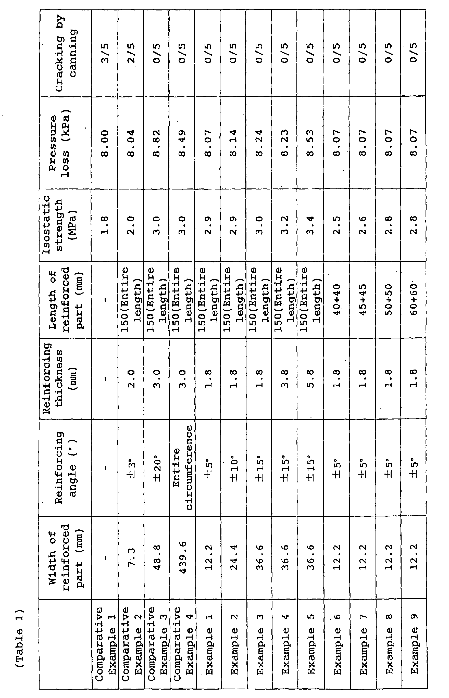
In Comparative Example 1, since the honeycomb structure
A was not reinforced, the isostatic strength was poor and
cracking was observed in three of five samples during canning.
In Comparative Example 2, since the reinforcing width was too
short, the isostatic strength did not increase, and cracking
was observed in two of five samples during canning. In
Comparative Examples 3 and 4, since the width of the reinforced
part was too long, the degree of elevation of pressure loss
relative to increase in isostatic strength was significant.
Contrarily, in Examples 1 to 9, since the reinforcing thickness,
width of reinforced part (and reinforcing angle) fell within
the ranges according to the present invention, it was possible
to increase the isostatic strength while suppressing elevation
of pressure loss.
As explained in the above description, since the
honeycomb structure according to the first aspect of the present
invention had a thickness and a width of reinforced part falling
within predetermined ranges, it was possible to set the
isostatic strength higher, realize a honeycomb structure having
resistance to breakage and keep the elevation of pressure loss
low. Furthermore, since the exhaust emission control system
according to the second aspect uses the honeycomb structure of
the first aspect, the system is low in pressure loss and high
in strength, suggesting a wide range of applications.
Furthermore, according to the manufacturing method of the third
aspect, it was possible to manufacture the honeycomb structure
of the first aspect in favorable manner.
Claims (14)
- A honeycomb structure comprising:characterized in that the honeycomb structure has a reinforced part in a part of the outer wall, and the reinforced part in the cross section perpendicular to the axial direction of the honeycomb structure lies at least in the range from the point located at 40° on the outer wall to the point located at 50° on the outer wall and within the range from the point located at 30° on the outer wall to the point located at 60° on the outer wall, with respect to the longitudinal direction of the partition wall about a sectional center of the honeycomb structure; and a mean thickness of the reinforced part in the perpendicular cross-section in the direction of the sectional center is in the range of 1 to 10 mm.an outer wall;partition walls disposed inside the outer wall; anda plurality of cells partitioned from one another by the partition walls, extending in the axial direction, each cell having a generally rectangular cross-section shape in the direction perpendicular to the axial direction;
- The honeycomb structure according to claim 1, wherein the reinforced part is formed by plugging
- The honeycomb structure according to claim 1 or 2, wherein a sum of length of the reinforced part in the axial direction of the honeycomb structure is preferably 1/3 or more relative to whole length of the honeycomb structure in the axial direction.
- The honeycomb structure according to any of claims 1 to 3, wherein the partition walls and the outer wall contain ceramics as a main component.
- The honeycomb structure according to claim 4, wherein a main component of the ceramics is one or more kinds selected from the group consisting of alumina, mullite, lithium aluminum silicate, cordierite, silicon carbide and silicon nitride.
- The honeycomb structure according to any of claims 1 to 5, wherein porosity of the partition wall is 50% or more.
- The honeycomb structure according to any of claims 1 to 6, wherein compressive strength in the axial direction is in a range of 0.5 to 10 MPa.
- The honeycomb structure according to any of claims 1 to 7, wherein opening ends of predetermined cells are plugged at one end face and opening ends of a predetermined cells of the remaining cells are plugged at the other end face.
- The honeycomb structure according to claim 8, wherein a catalyst capable of promoting combustion of diesel fine particles is held by the honeycomb structure.
- An exhaust emission control system comprising:characterized in that the emission control apparatus includes at least one honeycomb structure according to any one of claims 1 to 9, and further includes a cushioning material disposed on the outer circumference of the honeycomb structure and a can holding at least therein the honeycomb structure via the cushioning material.an internal combustion engine;an exhaust pipe for discharging an exhaust gas from the internal combustion engine; andan emission control apparatus, connected to the exhaust pipe, for cleaning the exhaust gas,
- A method of manufacturing a honeycomb structure having an outer wall; partition walls disposed inside the outer wall; a plurality of cells partitioned from one another by the partition walls, extending in the axial direction, each cell having a generally rectangular cross-section shape in the direction perpendicular to the axial direction; and a reinforced part provided in a part of the outer wall, the method comprising the steps of:characterized in that the reinforcing step is to form the reinforced part such that it lies at least in the range from the point located at 40° on the outer wall to the point located at 50° on the outer wall and within the range from the point located at 30° on the outer wall to the point located at 60° on the outer wall, with respect to the longitudinal direction of the partition wall about a sectional center of the honeycomb structure; and a mean thickness of the reinforced part in the perpendicular cross-section in the direction of the sectional center is in the range of 1 to 10 mm.forming a formed body of the honeycomb structure;firing the formed body to form a fired body; andreinforcing for formation of the reinforced part,
- The method of manufacturing a honeycomb structure according to claim 11, wherein the reinforcing step is plugging opening ends of at least two adjacent cells located within the predetermined range on the same end face.
- The method of manufacturing a honeycomb structure according to claim 11, wherein the reinforcing step includes cutting at least part of the fired body in the predetermined range and disposing a reinforcing material in the cut part.
- The method of manufacturing a honeycomb structure according to claim 13, wherein the cutting step includes cutting the outer circumference of the fired body and cutting at least part of the partition wall within the predetermined range.
Applications Claiming Priority (3)
| Application Number | Priority Date | Filing Date | Title |
|---|---|---|---|
| JP2002063723 | 2002-03-08 | ||
| JP2002063723A JP2003260322A (en) | 2002-03-08 | 2002-03-08 | Honeycomb structure, manufacturing method thereof and exhaust gas purification system |
| PCT/JP2003/002738 WO2003076047A1 (en) | 2002-03-08 | 2003-03-07 | Honeycomb structural body, method of manufacturing the structural body, and exhaust emission control system |
Publications (2)
| Publication Number | Publication Date |
|---|---|
| EP1484100A1 true EP1484100A1 (en) | 2004-12-08 |
| EP1484100A4 EP1484100A4 (en) | 2006-07-05 |
Family
ID=27800202
Family Applications (1)
| Application Number | Title | Priority Date | Filing Date |
|---|---|---|---|
| EP03744023A Withdrawn EP1484100A4 (en) | 2002-03-08 | 2003-03-07 | Honeycomb structure, method of manufacturing the structure, and exhaust emission control system |
Country Status (6)
| Country | Link |
|---|---|
| US (1) | US7867456B2 (en) |
| EP (1) | EP1484100A4 (en) |
| JP (1) | JP2003260322A (en) |
| AU (1) | AU2003211839A1 (en) |
| PL (1) | PL373785A1 (en) |
| WO (1) | WO2003076047A1 (en) |
Cited By (7)
| Publication number | Priority date | Publication date | Assignee | Title |
|---|---|---|---|---|
| EP1535664A1 (en) * | 2003-11-13 | 2005-06-01 | Ngk Insulators, Ltd. | Ceramic honeycomb structure |
| EP1580181A2 (en) | 2004-03-24 | 2005-09-28 | Ngk Insulators, Ltd. | Honeycomb structure and method of manufacturing the same |
| EP1704920A1 (en) * | 2005-03-24 | 2006-09-27 | Ngk Insulators, Ltd. | Method for manufacturing honeycomb structure and the honeycomb structure |
| WO2007066671A1 (en) | 2005-12-07 | 2007-06-14 | Ngk Insulators, Ltd. | Honeycomb structure body and method of producing the same |
| FR2906159A1 (en) * | 2006-09-27 | 2008-03-28 | Saint Gobain Ct Recherches | MONOLITHIC ELEMENT WITH REINFORCED CORNERS FOR FILTRATION OF PARTICLES |
| EP2508242A1 (en) * | 2011-03-31 | 2012-10-10 | NGK Insulators, Ltd. | Plugged honeycomb structure |
| EP2514503A1 (en) * | 2011-03-31 | 2012-10-24 | NGK Insulators, Ltd. | Plugged honeycomb structure |
Families Citing this family (37)
| Publication number | Priority date | Publication date | Assignee | Title |
|---|---|---|---|---|
| FR2864575B1 (en) * | 2003-12-24 | 2006-02-10 | Saint Gobain Ct Recherches | BLOCK FOR FILTRATION OF PARTICLES CONTAINED IN THE EXHAUST GASES OF AN INTERNAL COMBUSTION ENGINE |
| WO2005099865A1 (en) * | 2004-04-05 | 2005-10-27 | Ibiden Co., Ltd. | Honeycomb structure, method of manufacturing honeycomb structure, and exhaust emission control device |
| JPWO2005108328A1 (en) * | 2004-05-06 | 2008-03-21 | イビデン株式会社 | Honeycomb structure and manufacturing method thereof |
| US7393386B2 (en) * | 2004-10-06 | 2008-07-01 | Fleetguard, Inc. | Exhaust aftertreatment filter with residual stress control |
| WO2006137164A1 (en) * | 2005-06-24 | 2006-12-28 | Ibiden Co., Ltd. | Honeycomb structure body |
| WO2006137151A1 (en) | 2005-06-24 | 2006-12-28 | Ibiden Co., Ltd. | Honeycomb structure and exhaust gas purifier |
| JP4607689B2 (en) * | 2005-07-07 | 2011-01-05 | 日本碍子株式会社 | Honeycomb structure |
| FR2889080B1 (en) * | 2005-07-28 | 2007-11-23 | Saint Gobain Ct Recherches | CATALYTIC SUPPORT AND FILTER BASED ON SILICON CARBIDE AND HIGH SPECIFIC SURFACE |
| WO2007023653A1 (en) * | 2005-08-26 | 2007-03-01 | Ibiden Co., Ltd. | Honeycomb structure and process for producing the same |
| EP1757351B1 (en) | 2005-08-26 | 2016-04-13 | Ibiden Co., Ltd. | Honeycomb structure and manufacturing method thereof |
| JP4616752B2 (en) | 2005-10-26 | 2011-01-19 | 日本碍子株式会社 | Honeycomb structure |
| JP5144075B2 (en) * | 2006-03-30 | 2013-02-13 | 日本碍子株式会社 | Honeycomb structure and manufacturing method thereof |
| US7674513B2 (en) * | 2006-03-31 | 2010-03-09 | Corning Incorporated | Crack-resistant ceramic honeycomb structures |
| DE102006057280A1 (en) * | 2006-12-05 | 2008-06-12 | Robert Bosch Gmbh | By extrusion produced filter element for filtering exhaust gases of a diesel internal combustion engine |
| KR20090125033A (en) | 2007-03-27 | 2009-12-03 | 니뽄 가이시 가부시키가이샤 | Sealed honeycomb structure |
| KR20100014262A (en) * | 2007-03-27 | 2010-02-10 | 니뽄 가이시 가부시키가이샤 | Plugged honeycomb structure |
| WO2008120385A1 (en) | 2007-03-29 | 2008-10-09 | Ibiden Co., Ltd. | Honeycomb structure, process for producing the same, exhaust gas purification apparatus and process for manufacturing the apparatus |
| EP2160231A2 (en) * | 2007-05-04 | 2010-03-10 | Dow Global Technologies Inc. | Improved honeycomb filters |
| JPWO2009035049A1 (en) * | 2007-09-14 | 2010-12-24 | 日本碍子株式会社 | Manufacturing method of honeycomb filter |
| JP5053224B2 (en) * | 2008-10-09 | 2012-10-17 | 本田技研工業株式会社 | Exhaust purification filter |
| JP4896171B2 (en) * | 2009-03-13 | 2012-03-14 | 日本碍子株式会社 | Manufacturing method of honeycomb filter |
| JP2010227755A (en) * | 2009-03-26 | 2010-10-14 | Ngk Insulators Ltd | Ceramic honeycomb structure |
| US8491295B2 (en) * | 2009-05-28 | 2013-07-23 | Corning Incorporated | Die assembly and method of extruding cellular ceramic substrates with a skin |
| JP5791391B2 (en) * | 2010-06-28 | 2015-10-07 | 京セラ株式会社 | Honeycomb structure and gas processing apparatus using the same |
| EP2656902B1 (en) * | 2010-12-24 | 2018-03-21 | NGK Insulators, Ltd. | Honeycomb structure |
| JP5908345B2 (en) * | 2011-06-07 | 2016-04-26 | 住友化学株式会社 | Die for forming honeycomb structure and method for manufacturing honeycomb structure using the same |
| WO2013141244A1 (en) * | 2012-03-19 | 2013-09-26 | 京セラ株式会社 | Honeycomb structure body and gas-processing apparatus provided with same |
| US9475245B2 (en) * | 2012-05-08 | 2016-10-25 | Corning Incorporated | Honeycomb extrusion apparatus and methods |
| JP5514871B2 (en) * | 2012-07-26 | 2014-06-04 | 本田技研工業株式会社 | Exhaust purification filter |
| JP2014180600A (en) * | 2013-03-18 | 2014-09-29 | Ngk Insulators Ltd | Honeycomb filter |
| JP6120633B2 (en) * | 2013-03-27 | 2017-04-26 | 日本碍子株式会社 | Honeycomb structure |
| JP6749853B2 (en) * | 2017-01-31 | 2020-09-02 | 日本碍子株式会社 | Honeycomb structure manufacturing method and honeycomb structure |
| JP6767891B2 (en) * | 2017-01-31 | 2020-10-14 | 日本碍子株式会社 | Honeycomb structure manufacturing method and honeycomb structure |
| JP6615802B2 (en) * | 2017-02-06 | 2019-12-04 | 日本碍子株式会社 | Method for manufacturing plugged honeycomb structure |
| CN108278142A (en) * | 2017-12-27 | 2018-07-13 | 山东国瓷功能材料股份有限公司 | A kind of ceramic honey comb plug-hole structure |
| JP6797147B2 (en) * | 2018-03-27 | 2020-12-09 | 日本碍子株式会社 | Method for manufacturing honeycomb molded body and honeycomb structure |
| RS20241275A1 (en) * | 2024-11-18 | 2026-05-29 | Nanogroup Doo | Mechanical nano ap filter for the removal of impurities, dust and pm particles from individual chimney with a nano coating based on silicon dioxide |
Family Cites Families (26)
| Publication number | Priority date | Publication date | Assignee | Title |
|---|---|---|---|---|
| JPS54150406A (en) * | 1978-05-18 | 1979-11-26 | Nippon Soken | Ceramic honeycomb structure |
| JPS55142189A (en) * | 1979-04-24 | 1980-11-06 | Ngk Spark Plug Co | Honeycomb structure body |
| JPS55155741A (en) | 1979-05-22 | 1980-12-04 | Ngk Spark Plug Co Ltd | Honeycomb structural body |
| JPS56129042A (en) | 1980-03-14 | 1981-10-08 | Ngk Insulators Ltd | Honeycomb structure of ceramic |
| JPS5713211A (en) * | 1980-06-30 | 1982-01-23 | Nippon Soken Inc | Minute particle purifier for internal combustion engine |
| US4535589A (en) * | 1981-05-26 | 1985-08-20 | Nippon Soken, Inc. | Exhaust gas cleaning device for internal combustion engine |
| JPS5845715A (en) | 1981-09-14 | 1983-03-17 | Ngk Insulators Ltd | Ceramic honeycomb filter |
| JPS6245439A (en) | 1985-08-22 | 1987-02-27 | Mitsubishi Heavy Ind Ltd | Ultrasonic permeability improving method for stainless steel castings |
| JPH0356354Y2 (en) * | 1986-04-08 | 1991-12-18 | ||
| JPS63185425A (en) * | 1987-01-28 | 1988-08-01 | Ngk Insulators Ltd | Ceramic honeycomb filter for cleaning exhaust gas |
| JPH0243955A (en) | 1988-08-02 | 1990-02-14 | Ngk Insulators Ltd | Honeycomb structure and preparation thereof |
| JPH074534B2 (en) | 1988-09-22 | 1995-01-25 | 日本碍子株式会社 | Honeycomb structure and manufacturing method thereof |
| JP2604876B2 (en) * | 1990-03-27 | 1997-04-30 | 日本碍子株式会社 | Method for manufacturing ceramic honeycomb structure |
| US5629067A (en) * | 1992-01-30 | 1997-05-13 | Ngk Insulators, Ltd. | Ceramic honeycomb structure with grooves and outer coating, process of producing the same, and coating material used in the honeycomb structure |
| US5526462A (en) * | 1993-03-22 | 1996-06-11 | Ngk Insulators, Ltd. | Honeycomb heater with mounting means preventing axial-displacement and absorbing radial displacement |
| JP3768550B2 (en) * | 1994-03-11 | 2006-04-19 | 日本碍子株式会社 | Ceramic honeycomb structure |
| US5996228A (en) * | 1995-04-13 | 1999-12-07 | Mitsubishi Chemical Corporation | Monolith-holding element, process for producing the same, catalytic converter using a monolith member and process for producing the same |
| EP0745416B1 (en) * | 1995-06-02 | 2003-09-17 | Corning Incorporated | Device for removal of contaminants from fluid streams |
| JP3660031B2 (en) * | 1995-10-16 | 2005-06-15 | 本田技研工業株式会社 | Catalytic converter |
| JP3355943B2 (en) * | 1996-07-18 | 2002-12-09 | 松下電器産業株式会社 | Exhaust gas purification method and exhaust gas filter and exhaust gas filter purification device using the same |
| WO1999017006A1 (en) * | 1997-09-30 | 1999-04-08 | Emitec Gesellschaft Für Emissionstechnologie Mbh | Honeycomb body structure with supporting sections |
| JP4159155B2 (en) * | 1998-01-22 | 2008-10-01 | 株式会社日本自動車部品総合研究所 | Ceramic honeycomb structure and extrusion mold |
| JP2001261428A (en) | 2000-03-14 | 2001-09-26 | Ngk Insulators Ltd | Ceramic honeycomb structure |
| KR100518111B1 (en) * | 2000-03-22 | 2005-10-04 | 이비덴 가부시키가이샤 | Catalyst converter and diesel particulate filter system |
| JP3925225B2 (en) * | 2001-03-28 | 2007-06-06 | 株式会社デンソー | Exhaust gas purification filter and manufacturing method thereof |
| JP2003026488A (en) | 2001-07-13 | 2003-01-29 | Ngk Insulators Ltd | Honeycomb structure with reinforced surface and method for strengthening the same |
-
2002
- 2002-03-08 JP JP2002063723A patent/JP2003260322A/en active Pending
-
2003
- 2003-03-07 AU AU2003211839A patent/AU2003211839A1/en not_active Abandoned
- 2003-03-07 PL PL03373785A patent/PL373785A1/en unknown
- 2003-03-07 EP EP03744023A patent/EP1484100A4/en not_active Withdrawn
- 2003-03-07 US US10/502,775 patent/US7867456B2/en not_active Expired - Lifetime
- 2003-03-07 WO PCT/JP2003/002738 patent/WO2003076047A1/en not_active Ceased
Cited By (16)
| Publication number | Priority date | Publication date | Assignee | Title |
|---|---|---|---|---|
| EP1535664A1 (en) * | 2003-11-13 | 2005-06-01 | Ngk Insulators, Ltd. | Ceramic honeycomb structure |
| US7465486B2 (en) | 2003-11-13 | 2008-12-16 | Ngk Insulators, Ltd. | Ceramic honeycomb structure |
| US7429285B2 (en) | 2004-03-24 | 2008-09-30 | Ngk Insulators, Ltd. | Honeycomb structure and method of manufacturing the same |
| EP1580181A2 (en) | 2004-03-24 | 2005-09-28 | Ngk Insulators, Ltd. | Honeycomb structure and method of manufacturing the same |
| EP1580181A3 (en) * | 2004-03-24 | 2006-09-20 | Ngk Insulators, Ltd. | Honeycomb structure and method of manufacturing the same |
| EP1704920A1 (en) * | 2005-03-24 | 2006-09-27 | Ngk Insulators, Ltd. | Method for manufacturing honeycomb structure and the honeycomb structure |
| US7560154B2 (en) | 2005-03-24 | 2009-07-14 | Ngk Insulators, Ltd. | Method for manufacturing honeycomb structure and the honeycomb structure |
| WO2007066671A1 (en) | 2005-12-07 | 2007-06-14 | Ngk Insulators, Ltd. | Honeycomb structure body and method of producing the same |
| EP1967265A4 (en) * | 2005-12-07 | 2011-11-16 | Ngk Insulators Ltd | BODY HAVING A BEAT STRUCTURE AND METHOD FOR PRODUCING THE SAME |
| WO2008037919A1 (en) * | 2006-09-27 | 2008-04-03 | Saint-Gobain Centre De Recherches Et D'etudes Europeen | Monolithic member with reinforced corners for particle filtration |
| FR2906159A1 (en) * | 2006-09-27 | 2008-03-28 | Saint Gobain Ct Recherches | MONOLITHIC ELEMENT WITH REINFORCED CORNERS FOR FILTRATION OF PARTICLES |
| US7658779B2 (en) | 2006-09-27 | 2010-02-09 | Saint-Gobain Centre De Recherches Et D'etudes European | Monolithic element with reinforced corners for the filtration of particles |
| EA015284B1 (en) * | 2006-09-27 | 2011-06-30 | Сэн-Гобэн Сантр Де Решерш Э Д'Этюд Эропеен | Monolithic member with reinforced corners for particle filtration |
| CN101517206B (en) * | 2006-09-27 | 2011-12-14 | 欧洲技术研究圣戈班中心 | Monolithic member with reinforced corners for particle filtration |
| EP2508242A1 (en) * | 2011-03-31 | 2012-10-10 | NGK Insulators, Ltd. | Plugged honeycomb structure |
| EP2514503A1 (en) * | 2011-03-31 | 2012-10-24 | NGK Insulators, Ltd. | Plugged honeycomb structure |
Also Published As
| Publication number | Publication date |
|---|---|
| US20050095179A1 (en) | 2005-05-05 |
| JP2003260322A (en) | 2003-09-16 |
| PL373785A1 (en) | 2005-09-19 |
| US7867456B2 (en) | 2011-01-11 |
| WO2003076047A1 (en) | 2003-09-18 |
| AU2003211839A1 (en) | 2003-09-22 |
| EP1484100A4 (en) | 2006-07-05 |
Similar Documents
| Publication | Publication Date | Title |
|---|---|---|
| US7867456B2 (en) | Honeycomb structure, method of manufacturing the structure, and exhaust emission control system | |
| EP1440722B1 (en) | Honeycomb filter | |
| EP1679109B1 (en) | Ceramic honeycomb filter and method for production thereof, and sealing material for ceramic honeycomb filter | |
| EP2343113B1 (en) | Honeycomb structure | |
| EP1502639A1 (en) | Honeycomb filter | |
| EP2737945A1 (en) | Honeycomb Catalyst Body | |
| EP1473445A1 (en) | Honeycomb structure | |
| EP2705891A1 (en) | Plugged honeycomb structure | |
| CN107159316B (en) | Honeycomb structure | |
| WO2014061320A1 (en) | Dust-collecting honeycomb filter | |
| EP2236482A2 (en) | Ceramic honeycomb structure | |
| EP2668990A1 (en) | Honeycomb structure | |
| JP7799542B2 (en) | Honeycomb Filter | |
| JP4495152B2 (en) | Honeycomb structure and manufacturing method thereof | |
| JP2018167200A (en) | Honeycomb filter | |
| CN109833693B (en) | Honeycomb filter | |
| US11058983B2 (en) | Honeycomb filter | |
| JP7799541B2 (en) | Honeycomb Filter | |
| JP7094193B2 (en) | Honeycomb filter | |
| JP6084497B2 (en) | Honeycomb filter | |
| EP2221099B1 (en) | Honeycomb structure | |
| US12226727B2 (en) | Honeycomb filter | |
| KR20090030310A (en) | Filters comprising a plurality of honeycomb elements joined together in an offset assembly | |
| US12162805B2 (en) | Porous honeycomb structure and method for manufacturing same | |
| CN218166340U (en) | Honeycomb filter |
Legal Events
| Date | Code | Title | Description |
|---|---|---|---|
| PUAI | Public reference made under article 153(3) epc to a published international application that has entered the european phase |
Free format text: ORIGINAL CODE: 0009012 |
|
| 17P | Request for examination filed |
Effective date: 20040824 |
|
| AK | Designated contracting states |
Kind code of ref document: A1 Designated state(s): AT BE BG CH CY CZ DE DK EE ES FI FR GB GR HU IE IT LI LU MC NL PT RO SE SI SK TR |
|
| AX | Request for extension of the european patent |
Extension state: AL LT LV MK |
|
| A4 | Supplementary search report drawn up and despatched |
Effective date: 20060606 |
|
| 17Q | First examination report despatched |
Effective date: 20080527 |
|
| STAA | Information on the status of an ep patent application or granted ep patent |
Free format text: STATUS: THE APPLICATION IS DEEMED TO BE WITHDRAWN |
|
| 18D | Application deemed to be withdrawn |
Effective date: 20110405 |