EP1484079A1 - Stent for intracranial vascular therapy and process for producing the same - Google Patents
Stent for intracranial vascular therapy and process for producing the same Download PDFInfo
- Publication number
- EP1484079A1 EP1484079A1 EP03743983A EP03743983A EP1484079A1 EP 1484079 A1 EP1484079 A1 EP 1484079A1 EP 03743983 A EP03743983 A EP 03743983A EP 03743983 A EP03743983 A EP 03743983A EP 1484079 A1 EP1484079 A1 EP 1484079A1
- Authority
- EP
- European Patent Office
- Prior art keywords
- stent
- struts
- intracranial
- stainless steel
- vascular therapy
- Prior art date
- Legal status (The legal status is an assumption and is not a legal conclusion. Google has not performed a legal analysis and makes no representation as to the accuracy of the status listed.)
- Withdrawn
Links
Images


Classifications
-
- A—HUMAN NECESSITIES
- A61—MEDICAL OR VETERINARY SCIENCE; HYGIENE
- A61F—FILTERS IMPLANTABLE INTO BLOOD VESSELS; PROSTHESES; DEVICES PROVIDING PATENCY TO, OR PREVENTING COLLAPSING OF, TUBULAR STRUCTURES OF THE BODY, e.g. STENTS; ORTHOPAEDIC, NURSING OR CONTRACEPTIVE DEVICES; FOMENTATION; TREATMENT OR PROTECTION OF EYES OR EARS; BANDAGES, DRESSINGS OR ABSORBENT PADS; FIRST-AID KITS
- A61F2/00—Filters implantable into blood vessels; Prostheses, i.e. artificial substitutes or replacements for parts of the body; Appliances for connecting them with the body; Devices providing patency to, or preventing collapsing of, tubular structures of the body, e.g. stents
- A61F2/02—Prostheses implantable into the body
- A61F2/04—Hollow or tubular parts of organs, e.g. bladders, tracheae, bronchi or bile ducts
- A61F2/06—Blood vessels
- A61F2/07—Stent-grafts
-
- A—HUMAN NECESSITIES
- A61—MEDICAL OR VETERINARY SCIENCE; HYGIENE
- A61F—FILTERS IMPLANTABLE INTO BLOOD VESSELS; PROSTHESES; DEVICES PROVIDING PATENCY TO, OR PREVENTING COLLAPSING OF, TUBULAR STRUCTURES OF THE BODY, e.g. STENTS; ORTHOPAEDIC, NURSING OR CONTRACEPTIVE DEVICES; FOMENTATION; TREATMENT OR PROTECTION OF EYES OR EARS; BANDAGES, DRESSINGS OR ABSORBENT PADS; FIRST-AID KITS
- A61F2/00—Filters implantable into blood vessels; Prostheses, i.e. artificial substitutes or replacements for parts of the body; Appliances for connecting them with the body; Devices providing patency to, or preventing collapsing of, tubular structures of the body, e.g. stents
- A61F2/82—Devices providing patency to, or preventing collapsing of, tubular structures of the body, e.g. stents
- A61F2/86—Stents in a form characterised by the wire-like elements; Stents in the form characterised by a net-like or mesh-like structure
- A61F2/90—Stents in a form characterised by the wire-like elements; Stents in the form characterised by a net-like or mesh-like structure characterised by a net-like or mesh-like structure
- A61F2/91—Stents in a form characterised by the wire-like elements; Stents in the form characterised by a net-like or mesh-like structure characterised by a net-like or mesh-like structure made from perforated sheet material or tubes, e.g. perforated by laser cuts or etched holes
- A61F2/915—Stents in a form characterised by the wire-like elements; Stents in the form characterised by a net-like or mesh-like structure characterised by a net-like or mesh-like structure made from perforated sheet material or tubes, e.g. perforated by laser cuts or etched holes with bands having a meander structure, adjacent bands being connected to each other
-
- A—HUMAN NECESSITIES
- A61—MEDICAL OR VETERINARY SCIENCE; HYGIENE
- A61F—FILTERS IMPLANTABLE INTO BLOOD VESSELS; PROSTHESES; DEVICES PROVIDING PATENCY TO, OR PREVENTING COLLAPSING OF, TUBULAR STRUCTURES OF THE BODY, e.g. STENTS; ORTHOPAEDIC, NURSING OR CONTRACEPTIVE DEVICES; FOMENTATION; TREATMENT OR PROTECTION OF EYES OR EARS; BANDAGES, DRESSINGS OR ABSORBENT PADS; FIRST-AID KITS
- A61F2/00—Filters implantable into blood vessels; Prostheses, i.e. artificial substitutes or replacements for parts of the body; Appliances for connecting them with the body; Devices providing patency to, or preventing collapsing of, tubular structures of the body, e.g. stents
- A61F2/02—Prostheses implantable into the body
- A61F2/04—Hollow or tubular parts of organs, e.g. bladders, tracheae, bronchi or bile ducts
- A61F2/06—Blood vessels
-
- A—HUMAN NECESSITIES
- A61—MEDICAL OR VETERINARY SCIENCE; HYGIENE
- A61F—FILTERS IMPLANTABLE INTO BLOOD VESSELS; PROSTHESES; DEVICES PROVIDING PATENCY TO, OR PREVENTING COLLAPSING OF, TUBULAR STRUCTURES OF THE BODY, e.g. STENTS; ORTHOPAEDIC, NURSING OR CONTRACEPTIVE DEVICES; FOMENTATION; TREATMENT OR PROTECTION OF EYES OR EARS; BANDAGES, DRESSINGS OR ABSORBENT PADS; FIRST-AID KITS
- A61F2/00—Filters implantable into blood vessels; Prostheses, i.e. artificial substitutes or replacements for parts of the body; Appliances for connecting them with the body; Devices providing patency to, or preventing collapsing of, tubular structures of the body, e.g. stents
- A61F2/82—Devices providing patency to, or preventing collapsing of, tubular structures of the body, e.g. stents
- A61F2/86—Stents in a form characterised by the wire-like elements; Stents in the form characterised by a net-like or mesh-like structure
- A61F2/90—Stents in a form characterised by the wire-like elements; Stents in the form characterised by a net-like or mesh-like structure characterised by a net-like or mesh-like structure
- A61F2/91—Stents in a form characterised by the wire-like elements; Stents in the form characterised by a net-like or mesh-like structure characterised by a net-like or mesh-like structure made from perforated sheet material or tubes, e.g. perforated by laser cuts or etched holes
-
- A—HUMAN NECESSITIES
- A61—MEDICAL OR VETERINARY SCIENCE; HYGIENE
- A61L—METHODS OR APPARATUS FOR STERILISING MATERIALS OR OBJECTS IN GENERAL; DISINFECTION, STERILISATION OR DEODORISATION OF AIR; CHEMICAL ASPECTS OF BANDAGES, DRESSINGS, ABSORBENT PADS OR SURGICAL ARTICLES; MATERIALS FOR BANDAGES, DRESSINGS, ABSORBENT PADS OR SURGICAL ARTICLES
- A61L27/00—Materials for grafts or prostheses or for coating grafts or prostheses
- A61L27/02—Inorganic materials
- A61L27/04—Metals or alloys
-
- A—HUMAN NECESSITIES
- A61—MEDICAL OR VETERINARY SCIENCE; HYGIENE
- A61M—DEVICES FOR INTRODUCING MEDIA INTO, OR ONTO, THE BODY; DEVICES FOR TRANSDUCING BODY MEDIA OR FOR TAKING MEDIA FROM THE BODY; DEVICES FOR PRODUCING OR ENDING SLEEP OR STUPOR
- A61M29/00—Dilators with or without means for introducing media, e.g. remedies
- A61M29/02—Dilators made of swellable material
-
- A—HUMAN NECESSITIES
- A61—MEDICAL OR VETERINARY SCIENCE; HYGIENE
- A61F—FILTERS IMPLANTABLE INTO BLOOD VESSELS; PROSTHESES; DEVICES PROVIDING PATENCY TO, OR PREVENTING COLLAPSING OF, TUBULAR STRUCTURES OF THE BODY, e.g. STENTS; ORTHOPAEDIC, NURSING OR CONTRACEPTIVE DEVICES; FOMENTATION; TREATMENT OR PROTECTION OF EYES OR EARS; BANDAGES, DRESSINGS OR ABSORBENT PADS; FIRST-AID KITS
- A61F2/00—Filters implantable into blood vessels; Prostheses, i.e. artificial substitutes or replacements for parts of the body; Appliances for connecting them with the body; Devices providing patency to, or preventing collapsing of, tubular structures of the body, e.g. stents
- A61F2/82—Devices providing patency to, or preventing collapsing of, tubular structures of the body, e.g. stents
- A61F2/86—Stents in a form characterised by the wire-like elements; Stents in the form characterised by a net-like or mesh-like structure
- A61F2/90—Stents in a form characterised by the wire-like elements; Stents in the form characterised by a net-like or mesh-like structure characterised by a net-like or mesh-like structure
- A61F2/91—Stents in a form characterised by the wire-like elements; Stents in the form characterised by a net-like or mesh-like structure characterised by a net-like or mesh-like structure made from perforated sheet material or tubes, e.g. perforated by laser cuts or etched holes
- A61F2/915—Stents in a form characterised by the wire-like elements; Stents in the form characterised by a net-like or mesh-like structure characterised by a net-like or mesh-like structure made from perforated sheet material or tubes, e.g. perforated by laser cuts or etched holes with bands having a meander structure, adjacent bands being connected to each other
- A61F2002/91525—Stents in a form characterised by the wire-like elements; Stents in the form characterised by a net-like or mesh-like structure characterised by a net-like or mesh-like structure made from perforated sheet material or tubes, e.g. perforated by laser cuts or etched holes with bands having a meander structure, adjacent bands being connected to each other within the whole structure different bands showing different meander characteristics, e.g. frequency or amplitude
-
- A—HUMAN NECESSITIES
- A61—MEDICAL OR VETERINARY SCIENCE; HYGIENE
- A61F—FILTERS IMPLANTABLE INTO BLOOD VESSELS; PROSTHESES; DEVICES PROVIDING PATENCY TO, OR PREVENTING COLLAPSING OF, TUBULAR STRUCTURES OF THE BODY, e.g. STENTS; ORTHOPAEDIC, NURSING OR CONTRACEPTIVE DEVICES; FOMENTATION; TREATMENT OR PROTECTION OF EYES OR EARS; BANDAGES, DRESSINGS OR ABSORBENT PADS; FIRST-AID KITS
- A61F2/00—Filters implantable into blood vessels; Prostheses, i.e. artificial substitutes or replacements for parts of the body; Appliances for connecting them with the body; Devices providing patency to, or preventing collapsing of, tubular structures of the body, e.g. stents
- A61F2/82—Devices providing patency to, or preventing collapsing of, tubular structures of the body, e.g. stents
- A61F2/86—Stents in a form characterised by the wire-like elements; Stents in the form characterised by a net-like or mesh-like structure
- A61F2/90—Stents in a form characterised by the wire-like elements; Stents in the form characterised by a net-like or mesh-like structure characterised by a net-like or mesh-like structure
- A61F2/91—Stents in a form characterised by the wire-like elements; Stents in the form characterised by a net-like or mesh-like structure characterised by a net-like or mesh-like structure made from perforated sheet material or tubes, e.g. perforated by laser cuts or etched holes
- A61F2/915—Stents in a form characterised by the wire-like elements; Stents in the form characterised by a net-like or mesh-like structure characterised by a net-like or mesh-like structure made from perforated sheet material or tubes, e.g. perforated by laser cuts or etched holes with bands having a meander structure, adjacent bands being connected to each other
- A61F2002/91533—Stents in a form characterised by the wire-like elements; Stents in the form characterised by a net-like or mesh-like structure characterised by a net-like or mesh-like structure made from perforated sheet material or tubes, e.g. perforated by laser cuts or etched holes with bands having a meander structure, adjacent bands being connected to each other characterised by the phase between adjacent bands
- A61F2002/91541—Adjacent bands are arranged out of phase
-
- A—HUMAN NECESSITIES
- A61—MEDICAL OR VETERINARY SCIENCE; HYGIENE
- A61F—FILTERS IMPLANTABLE INTO BLOOD VESSELS; PROSTHESES; DEVICES PROVIDING PATENCY TO, OR PREVENTING COLLAPSING OF, TUBULAR STRUCTURES OF THE BODY, e.g. STENTS; ORTHOPAEDIC, NURSING OR CONTRACEPTIVE DEVICES; FOMENTATION; TREATMENT OR PROTECTION OF EYES OR EARS; BANDAGES, DRESSINGS OR ABSORBENT PADS; FIRST-AID KITS
- A61F2/00—Filters implantable into blood vessels; Prostheses, i.e. artificial substitutes or replacements for parts of the body; Appliances for connecting them with the body; Devices providing patency to, or preventing collapsing of, tubular structures of the body, e.g. stents
- A61F2/82—Devices providing patency to, or preventing collapsing of, tubular structures of the body, e.g. stents
- A61F2/86—Stents in a form characterised by the wire-like elements; Stents in the form characterised by a net-like or mesh-like structure
- A61F2/90—Stents in a form characterised by the wire-like elements; Stents in the form characterised by a net-like or mesh-like structure characterised by a net-like or mesh-like structure
- A61F2/91—Stents in a form characterised by the wire-like elements; Stents in the form characterised by a net-like or mesh-like structure characterised by a net-like or mesh-like structure made from perforated sheet material or tubes, e.g. perforated by laser cuts or etched holes
- A61F2/915—Stents in a form characterised by the wire-like elements; Stents in the form characterised by a net-like or mesh-like structure characterised by a net-like or mesh-like structure made from perforated sheet material or tubes, e.g. perforated by laser cuts or etched holes with bands having a meander structure, adjacent bands being connected to each other
- A61F2002/9155—Adjacent bands being connected to each other
- A61F2002/91558—Adjacent bands being connected to each other connected peak to peak
-
- A—HUMAN NECESSITIES
- A61—MEDICAL OR VETERINARY SCIENCE; HYGIENE
- A61F—FILTERS IMPLANTABLE INTO BLOOD VESSELS; PROSTHESES; DEVICES PROVIDING PATENCY TO, OR PREVENTING COLLAPSING OF, TUBULAR STRUCTURES OF THE BODY, e.g. STENTS; ORTHOPAEDIC, NURSING OR CONTRACEPTIVE DEVICES; FOMENTATION; TREATMENT OR PROTECTION OF EYES OR EARS; BANDAGES, DRESSINGS OR ABSORBENT PADS; FIRST-AID KITS
- A61F2250/00—Special features of prostheses classified in groups A61F2/00 - A61F2/26 or A61F2/82 or A61F9/00 or A61F11/00 or subgroups thereof
- A61F2250/0058—Additional features; Implant or prostheses properties not otherwise provided for
- A61F2250/0096—Markers and sensors for detecting a position or changes of a position of an implant, e.g. RF sensors, ultrasound markers
- A61F2250/0098—Markers and sensors for detecting a position or changes of a position of an implant, e.g. RF sensors, ultrasound markers radio-opaque, e.g. radio-opaque markers
Definitions
- the present invention relates to a stent used for intracranial vascular therapy, and more specifically to a stent used for dilation therapy of a stenosed region formed in the intracranial blood vessels, and for coil embolization therapy of an aneurysm formed in the intracranial blood vessels.
- An example of therapies for angina pectoris and myocardial infarction derived from arteriosclerosis or the like is percutaneous angioplasty in which a stenosed region of the cardiac coronary arteries is dilated and recanalized by a balloon catheter inserted from outside of the body.
- the percutaneous therapy using a balloon catheter does not include surgical incision of an affected part and thus causes little damage to the tissue and makes an early recovery, as compared with a conventional surgical by-pass operation.
- the percutaneous therapy requires a short time for the therapy and significantly decreases a load on a patient.
- dilation therapy of a stenosed region of the cardiac coronary arteries using a balloon catheter has the large problem of causing restenosis in about 40% of patients after the passage of about 3 months to 6 months from the therapy.
- the use of a stent has been studied.
- a stent is a medical device which is held in a stenosed region formed in the vessels in living organisms, such as the blood vessels, the esophagus, the trachea, the urethra, the bile duct, and the like, for effectively securing the lumen.
- the stent in a wound state is introduced in a vessel and placed in a desired stenosed region, and then it is expanded to predetermined dimensions and held in the stenosed region.
- a coil stent comprises a single wire coil or a plurality of wire coils bonded together by laser welding or the like according to demand.
- the coil stent has the advantage that it has excellent flexibility, can easily reach a tortuous blood vessel, and causes little obstruction in the side branches.
- the coil stent has the disadvantage of slightly low radial force.
- a slotted tube stent comprises a tube-shaped base material having openings formed therein by laser processing or the like. Although the slotted tube stent has the advantage of high radial force, it has the disadvantage that it has relatively low flexibility and easily causes obstruction in the side branches.
- the designs of both the coil stent and the slotted tube stent can be improved to satisfy both the flexibility and radial force, and thus both stents are widely used.
- FIG. 1 is an expansion plan view of a typical stent.
- a stent 1 generally comprises, as its constituents, main struts 2 greatly contributing to the expression of radial force, link struts 3 greatly contributing to the expression of flexibility, and openings (cells 4) defined by the main struts 2 and the link struts 3.
- the radial force and flexibility of the stent 1 are determined by the shapes and dimensions of the main struts 2, the link struts, 3 and the cells 4.
- stents are roughly divided into the following two types according to the mechanisms for expanding stents to the predetermined dimensions:
- One of the types is a self-expandable stent comprising a shape-memory alloy and being expandable without mechanical expansion.
- the other type is a balloon-expandable stent requiring mechanical expansion and being expanded by a known balloon catheter generally used for dilation therapy of a stenosed region of the vessels, particularly the arteries or the veins.
- a clipping operation has been conventionally conducted in which the root of an aneurysm is clipped in craniotomy, for preventing rupture of the aneurysm.
- coil embolization therapy has been increasingly popularized in which an aneurysm is embolized by a metal coil percutaneously inserted from outside the body, for preventing rupture.
- medical checkups of the brain are popularized, and thus aneurysms are often discovered in checkups.
- Most of such patients have no subjective symptom, and the coil embolization therapy having lower invasion than a conventional clipping-operation requiring craniotomy is useful for the patients.
- coil embolization therapy of intracranial aneurysms has the large problem of limiting applicable cases. Namely, it is pointed out that there is the danger that a coil held in an aneurysm such as a wide neck aneurysm or a fusiform aneurysm having a large width at its root easily migrates to the parent blood vessel, and a thrombus formed in the migrating coil is dispersed by the bloodstream to cause cerebral infarction.
- the right and left vertebral arteries reaching the skull along the cervical vertebra are combined together to form the basilar artery in the skull.
- the basilar artery runs forward and branches into the right and left posterior cerebral arteries.
- the internal carotid arteries reaching the skull pass through the carotid artery siphon and branches into the posterior communicating artery in the occipital region, the middle cerebral artery in the temporal region, and the anterior cerebral arteries in the frontal region, and the right and left anterior cerebral arteries are connected by the anterior communicating artery.
- the right and left artery groups are connected in the order of the basilar artery, the posterior communicating artery, the anterior cerebral arteries, and the anterior communicating artery from the occipital region to the frontal region to form the arterial circle of cerebrum (circle of Willis).
- the circle of Willis It is known that most of aneurysms causing bleeding sources of subarachnoidal hemorrhage occur in the circle of Willis.
- a conceivable main cause of difficulty in safely holding a stent for the cardiac coronary arteries is that the stent for the cardiac coronary arteries cannot track the anatomically complicated tortuousness of the intracranial arteries.
- the cardiac coronary arteries are elastic arteries rich in elasticity, and are significantly affected by the heartbeat. Also, the cardiac coronary arteries have a certain degree of tortuousness, and thus a stent for the cardiac coronary arteries is designed to balance the radial force and flexibility.
- the intracranial arteries are muscular arteries and are little affected by the heartbeat because they are far from the heart. Therefore, it is easily understood that although the radial force of a stent used for the intracranial vessels is not so important, the flexibility for allowing the stent to track the carotid artery siphon and the circle of Willis having a higher degree of tortuousness than the cardiac coronary arteries is very important.
- the stent for the cardiac coronary arteries held in the intracranial arteries has low visibility under X-ray radioscopy.
- Low visibility causes difficulty in precisely holding the stent in a target site and difficulty in obtaining information of the properties of the held stent in each diagnosis after the operation, thereby causing difficulty in obtaining a sufficient therapeutic effect.
- the stent In observing the stent held in the intracranial arteries under X-ray radioscopy, the stent is observed through the skull regardless of the observation angle, and thus the visibility is possibly decreased by the influence of calcium contained in abundance in the bone components.
- PCT Japanese Translation Patent Publication No. 2001-504717 discloses a rolled sheet stent and stent catheter used for intracranial therapy.
- the rolled sheet stent is releasably mounted on the outer periphery of the distal tip of a catheter, and is held by a non-sliding release mechanism.
- the non-sliding release mechanism is operated remotely from the base end of the catheter so that the sheet stent can be held in a desired site.
- the sheet stent is self-expandable and comprises a plurality of cut slots for securing flexibility before or after expansion, the sheet stent essentially has an imperforate wall during expansion.
- Elgiloy composed of a cobalt-chromium-nickel alloy, Nitinol composed of a nickel-titanium alloy, stainless steel, and the like are disclosed as materials for the sheet stent. It is further disclosed that in order to increase visibility under X-ray radioscopy, the sheet stent is covered with a radiopaque material such as tin, tantalum, or the like, or a radiopaque maker comprising tantalum, platinum or gold is mounted on the sheet stent.
- bimetallic corrosion galvanic corrosion
- an object of the present invention is to provide a stent for intracranial vascular therapy and a process for producing the same which has flexibility for allowing the stent to be safely held in the intracranial arteries, induces no biological reaction in the blood vessels due to galvanic corrosion or the like, and has elevated visibility under X-ray radioscopy.
- the stent is made of a single material having higher radiopacity than that of stainless steel, and the main struts and the link struts each have a width ranging from 100 ⁇ m to 200 ⁇ m and a thickness ranging from 50 ⁇ m to 100 ⁇ m.
- the single material having higher radiopacity than that of stainless steel is preferably a metal, and more preferably gold or platinum.
- a process for producing the stent which is held in the intracranial blood vessels for intracranial vascular therapy and comprises a plurality of main struts and a plurality of link struts as its constituents each having an outer surface, an inner surface, and sides comprises a step (step a) of forming a copper layer on each of the outer surfaces, the inner surfaces, and the sides of main struts and link struts constituting a stent made of stainless steel; a step (step b) of burying the stent in a thermoplastic resin material so as to expose only the outer surfaces of the main struts and link struts coated with the copper layers; a step (step c) of forming single material layers having higher radiopacity than that of stainless steel on the outer surfaces of the struts coated with the copper layers; a step (step d) of removing the thermoplastic resin material; a step (step e) of removing the copper layers; and a step (step f) of detaching the
- the copper layers and/or the single material layers having higher radiopacity than that of stainless steel are preferably formed by plating, and more preferably electrolytic plating.
- a stent for intracranial vascular therapy and a process for producing the same according to embodiments of the present invention will be described in detail below.
- the structure and the design of a stent 1 for intracranial vascular therapy of the present invention are not limited as long as the stent 1 comprises a plurality of main struts 2, and a plurality of link struts 3 as its constituents.
- the stent may be a coil stent or a slotted tube stent, the slotted tube stent is preferred because the width 5 of the main struts, and the width 6 of the link struts, the thickness 7 of the main struts, and the thickness 8 of the link struts can be easily controlled.
- a mechanism for expanding the stent 1 to predetermined dimensions is also not limited.
- the stent 1 may be a self-expandable stent or a balloon-expandable stent.
- the stent 1 for intracranial therapy of the present invention comprises the plurality of main struts 2 and the plurality of link struts 3 as its constituents, and the stent 1 is made of a single material 11 having higher radiopacity than that of stainless steel. Also, the main struts 2 and the link struts 3 each have a width ranging from 100 ⁇ m to 200 ⁇ m and a thickness ranging from 50 ⁇ m to 100 ⁇ m.
- stainless steel is mainly used as a material for stents for the cardiac coronary arteries which can be diverted to intracranial vascular therapy.
- SUS316L stainless steel
- the stent for the cardiac coronary arteries is diverted to the intracranial blood vessels, there are the two disadvantages including the disadvantage that the stent cannot be safely held in the intracranial blood vessels because of its low trackability to the tortuous intracranial blood vessels, and the disadvantage that the stent exhibits low visibility in the intracranial blood vessels under X-ray radioscopy.
- stainless steel SUS316L
- a material having higher radiopacity than that of stainless steel must be used for the stent for intracranial vascular therapy of the present invention.
- the visibility of the stent in the intracranial blood vessels can be improved by increasing the thicknesses of the struts in comparison to the stent for the cardiac coronary arteries.
- an increase in the thicknesses of the struts inevitably decreases the flexibility of the stent to decrease the trackability to the tortuous intracranial blood vessels. It is thus important to use a material having higher X-rat radiopacity than stainless steel.
- the term “single” is defined not only as one type of material not containing other materials but also as a material without complete or partial coating. (However, for a metal, the term “single” means not only that the material comprises a single element but also that the material may comprise a single alloy. On the other hand, in the method of adding a radiopaque material to any one of various plastic materials as described below, exceptionally, only the number of the radiopaque materials used is counted, and a type of radiopaque material may be used.) Namely, the present invention does not include a radiopaque coating or a radiopaque marker provided on the stent for improving radiopacity, the coating or the marker having a composition different from the stent composition. The reason for this will be described in detail below.
- the radiopaque coating or the radiopaque marker mainly comprises a metal.
- the radiopaque coating or the radiopaque marker is provided on the stent for intracranial vascular therapy comprising a metal, different metals are joined together.
- bimetallic corrosion known as galvanic corrosion occurs under the wetting conditions such as in the blood vessels.
- the corrosion is due to electrochemical elution of the metals, and it induces inflammatory response in the blood vessels to quite possibly cause vascular obstruction or restenosis. Therefore, in order to prevent such response in the blood vessels, the stent 1 for the intracranial vascular therapy preferably comprises the single material 11.
- the material of the stent 1 for intracranial vascular therapy is preferably a metal, more preferably a metal having a density of 13 g/cm 3 or more, and most preferably gold or platinum.
- the material for the stent for intracranial vascular therapy is preferably a metal. Since the stent is permanently held in the blood vessels, gold or platinum inducing substantially no biological reaction is more preferred. Since gold or platinum has very high radiopacity, it is a preferred material from the viewpoint of increasing visibility in the skull.
- the main struts 2 and the link struts 3 which constitute the stent 1 for intracranial vascular therapy of the present invention
- the main struts 2 and the link struts 3 each have a width ranging from 100 ⁇ m to 200 ⁇ m and a thickness ranging from 50 ⁇ m to 100 ⁇ m.
- the stent 1 for intracranial vascular therapy can be designed for dilation therapy of a stenosed region and the purpose of preventing migration of an embolization coil, or the stent 1 for intracranial vascular therapy can be designed for a treated area such as the basilar artery, the circle of Willis, or the carotid artery siphon.
- a first required characteristic for the stent for intracranial vascular therapy is flexibility allowing the stent to track the highly tortuous blood vessels.
- a certain degree of radial force is required for dilating a stenosed region and preventing migration of the embolization coil.
- the radial force is greatly affected by the design of the stent, the radial force is substantially determined by a correlation between the widths and thicknesses of the main struts 2 and the link struts 3 in the case of the same design.
- the inventors found that when the width of each of the main struts 2 and the link struts 3 is less than 100 ⁇ m, or the thickness of each of the main struts 2 and the link struts 3 is less than 50 ⁇ m, the stent has the tendency that the flexibility is increased, while the radial force is relatively decreased, and thus the stent is unsuitable as the stent 1 for intracranial vascular therapy.
- the stent has the tendency that the radial force is increased, while the flexibility is relatively decreased, and thus the stent is unsuitable as the stent 1 for intracranial vascular therapy.
- the stent 1 for intracranial vascular therapy of the present invention is held in the intracranial blood vessels for intracranial vascular therapy and comprises the plurality of main struts 2 and the plurality of link struts 3 as its constituents each having an outer surface, an inner surface, and sides.
- the process for producing the stent 1 comprises a step (step a) of forming a copper layer 9 on each of the outer surfaces, the inner surfaces, and the sides of the main struts and the link struts constituting a stent 12 made of stainless steel, a step (step b) of burying the stent in a thermoplastic resin material 10 so as to expose only the outer surfaces of the main struts and link struts coated with the copper layers 9, a step (step c) of forming the single material layers 11 having higher radiopacity than that of stainless steel on the outer surfaces of the struts coated with the copper layers 9, a step (step d) of removing the thermoplastic resin material 10, a step (step e) of removing the copper layers 9, and a step (step f) of removing the single material layers 11 having higher radiopacity than that of stainless steel from the stent 12 made of stainless steel to prepare the stent 1 for intracranial vascular therapy.
- the stent 12 made of stainless steel is used as a template, and the width and thickness of each of the main struts 2 and the link struts 3 of the stent 1 for intracranial vascular therapy can be freely controlled by controlling the thicknesses of the copper layers 9 and the single material layers 11 having higher radiopacity than that of stainless steel.
- This control can facilitate the production of the stent 1 for intracranial vascular therapy for dilation therapy of a stenosed region and the purpose of preventing migration of the embolization coil, or the stent 1 for intracranial vascular therapy for a treated area such as the basilar artery, the circle of Willis, and the carotid artery siphon.
- the step a preferably comprises plating, and more preferably electrolytic plating.
- plating types include electrolytic plating, chemical plating, hot-dip plating, spray plating, evaporation plating, vapor plating, powder plating, and the like, electrolytic plating is preferred from the viewpoint of versatility and ease of control of plating thicknesses.
- the copper layers can easily be formed by electrolytic plating using the stainless steel stent 12 as a cathode and a copper plate or platinum-plated titanium as an anode in an acid copper plating bath containing 200 to 240 g/l of copper sulfate and 30 to 65 g/l of sulfuric acid.
- the bath temperature is preferably 20 to 50°C, and the bath is preferably stirred.
- the current density is preferably 2 to 8 A/dm 2 , and the thickness of the copper layers can be controlled by controlling the bath temperature, the current density, and the plating time.
- the composition of the plating bath is not limited to the above-described composition, and a known plating bath composition, or any one of various commercial plating baths is preferably used.
- the resin material 10 used in the step b is not particularly limited. Any resin material can be used as long as it is thermoplastic and soluble in a specified solvent. Preferred examples of such a resin material include polyester, polyester elastomer, polyamide, polyamide elastomer, polyurethane, polyurethane elastomer, polyolefin, polyolefin elastomer, polycarbonate, and the like. Also, the method for burying the stent 12 in the resin material 10 is not limited, and a known method can be used.
- the method for easily burying the stent 12 in the resin material 10 so as to expose only the outer surfaces of the struts comprises placing the stent 12 coated with the copper layers 9 on the outer surface of the resin-material 10, and placing a heat-shrinkable tube comprising a material which does not fuse with the resin material on the outer surface of the stent 12 and then shrinking the heat-shrinkable tube by heating to a temperature higher than the melting point of the resin material.
- the step b it is important to expose only the outer surfaces of the struts. If the sides of the struts are partially exposed, the single material layers 11 having higher radiopacity than that of stainless steel are formed on the outer surfaces and the sides of the struts in the step c, and thus the single material layers 11 having higher radiopacity than that of stainless steel cannot be easily detached as the stent 1 for intracranial vascular therapy in the step f.
- the step c preferably comprises plating, and more preferably electrolytic plating.
- plating types include electrolytic plating, chemical plating, hot-dip plating, spray plating, evaporation plating, vapor plating, powder plating, and the like, electrolytic plating is preferred from the viewpoint of versatility and ease of control of plating thicknesses.
- gold layers can easily be formed by electrolytic plating using the stainless steel stent 12 buried in the resin material 10 in the step b as a cathode and platinum-plated titanium as an anode in an acid bath containing 4 to 8 g/l of potassium cyanoaurate, 30 to 40 g/l of potassium citrate, 30 to 40 g/l of potassium primary phosphate, 20 to 30 g/l of citric acid, and 2 to 3 g/l of nickel ethylenediaminediacetate.
- the bath temperature is preferably 20 to 50°C, and the bath is preferably stirred.
- the current density is preferably 1 to 5 A/dm 2
- the thickness of the gold layers can be controlled by controlling the bath temperature, the current density, and the plating time.
- the composition of the plating bath is not limited to the above-described composition, and a known plating bath composition, or any one of various commercial plating baths (for example, TEMPEREX 8400 produced by Electroplating Engineers of Japan Ltd.) is preferably used.
- the platinum layers can easily be formed by electrolytic plating using the stainless steel stent 12 buried in the resin material 10 in the step b as a cathode and platinum-plated titanium as an anode in a phosphate bath containing 4 g/l of platinum tetrachloride pentahydrate, 20 g/l of ammonium hydrogenphosphate, and 100 g/l of sodium hydrogenphosphate dodecahydrate.
- the bath temperature is preferably 90 to 100°C, and the bath is preferably stirred.
- the current density is preferably 0.3 to 1 A/dm 2
- the thickness of the platinum layers can be controlled by controlling the bath temperature, the current density, and the plating time.
- the composition of the plating bath is not limited to the above-described composition, and a known plating bath composition, or any one of various commercial plating baths (for example, Platanex 3LS produced by Electroplating Engineers of Japan Ltd.) is preferably used.
- the resin material 10 is preferably dissolved in a good solvent for the thermoplastic resin material 10 used in the step b.
- a good solvent for the resin material 10 is preferably used.
- 1,1,1,3,3,3-hexafluoro-2-propanol can be used for removing only the resin material 10 by dissolving it within a short time.
- the copper layers 9 are preferably removed by dissolving in nitric acid.
- gold or platinum is used for the single material layers 11 having higher radiopacity than that of stainless steel, any of the metals is very stable to nitric acid, and thus nitric acid is preferably used.
- a necessary and sufficient washing step and drying step are preferably performed.
- electrolytic plating is performed in the steps a and c, hydrogen gas is produced by electrolysis.
- hydrogen gas is produced by dissolution of the copper layers 9 in nitric acid. Any of the steps possibly causes hydrogen brittle fracture which decreases the strength of the layers due to occlusion of the produced hydrogen gas in each layer.
- a baking treatment is preferably performed after each of the steps a, c, and e. Although, in the baking treatment after the step c, the melting point of the resin material 10 must be taken into consideration, each baking treatment is preferably performed in the range from 150 to 300°C.
- the stent 1 for intracranial vascular therapy of the present invention it is possible to preferably use known methods such as a method in which a pipe made of the single material 11 having higher radiopacity than that of stainless steel is processed into a stent shape by laser cutting, a method in which a wire made of the single material 11 having higher radiopacity than that of stainless steel is knitted into a stent shape, and the like.
- stents were produced by the same method as in Example 1 except that in the step c, electrolytic plating of gold was performed for 90 minutes to form gold layers of about 100 ⁇ m in thickness.
- stents were produced by the same method as in Example 1 except that in the step c, electrolytic plating was performed in a platinum plating bath at 80°C (Platanex 3LS produced by Electroplating Engineers of Japan Ltd.) under stirring with a magnetic stirrer with a current density of 2.0 A/dm 2 for 300 minutes to form platinum layers of about 60 ⁇ m in thickness on the outer surfaces of the stents.
- electrolytic plating was performed in a platinum plating bath at 80°C (Platanex 3LS produced by Electroplating Engineers of Japan Ltd.) under stirring with a magnetic stirrer with a current density of 2.0 A/dm 2 for 300 minutes to form platinum layers of about 60 ⁇ m in thickness on the outer surfaces of the stents.
- stents were produced by the same method as in Example 1 except that in the step c, electrolytic plating of gold was performed for 30 minutes to form gold layers of about 30 ⁇ m in thickness.
- stents were produced by the same method as in Example 1 except that in the step c, electrolytic plating of gold was performed for 120 minutes to form gold layers of about 110 ⁇ m in thickness.
- the widths and thicknesses of three main struts and three link struts of each of the stents of the examples and comparative examples were measured by using a micro highscope (VH-7000 produced by Keyence Corporation) under the condition of a magnification of x150.
- the average of three measurements was regarded as a measured value, and the average and standard deviation of the three stents are shown in Table 1.
- the stent of each of the examples and the comparative examples was placed on a balloon of a balloon catheter for PTCA (percutaneous transluminal coronary angioplasty) comprising a balloon of 3.0 ⁇ 20 mm, and clipped. Also, a silicon tube having an inner diameter of 3 mm and an outer diameter of 6 mm was set in hot water at 37°C, and the balloon was expanded in the silicon tube to hold the stent therein (pressing rate: 0.101 MPa/sec, pressure: 0.811 MPa, and pressing time: 30 sec). After holding, the silicon tube was incised to remove each stent, and damage to the main struts and the link struts was measured for evaluating the radial force.
- PTCA percutaneous transluminal coronary angioplasty
- the stent of each of the examples and the comparative examples was placed on a balloon of a balloon catheter 13 for PTCA (percutaneous transluminal coronary angioplasty) comprising a balloon of 3.0 ⁇ 20 mm, and clipped.
- PTCA percutaneous transluminal coronary angioplasty
- a simulated intracranial blood vessel 14 (made of high-density polyethylene and having an inner diameter of 3 mm, an outer diameter of 6 mm, and a radius of curvature of the first and second bends of 3 mm) comprising a first bend 14a and a second bend 14b was arranged in a flexible plate 15 in hot water at 37°C, and a guide wire 16 of 0.014" (0.3556 mm) was previously inserted into the simulated intracranial blood vessel.
- the balloon catheter 13 clipped with each stent was inserted into the simulated intracranial blood vessel at a rate of 10 mm/sec by using a slide table, and flexibility of each stent was evaluated by determining whether the stent could be inserted or not.
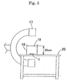
- a plastic vessel 18 was filled with distilled water 19 so that the distance between the bottom of the plastic vessel and the water surface was 20 cm.
- the stent 1 was placed at the bottom of the plastic vessel 18 set on an operating table 20, and contrast radiography was performed by using an X-ray contrast radiographic apparatus 17 (BV-300 produced by Philip Co,. Ltd.) to evaluate the visibility of each stent.
- Example 1 to 3 of the present invention no damage was observed in the main struts and the link struts in expansion of the balloon, and thus a certain degree of radial force was exhibited. Also, each of the stents could pass through the first and second bends of the simulated intracranial blood vessel, and thus sufficient flexibility was exhibited. Furthermore, since gold (Examples 1 and 2) and platinum (Example 3) were used as materials, high visibility was exhibited.
- the stent had high radial force, but it could not pass through the second bend, thereby exhibiting slightly poor flexibility. Furthermore, since SUS316L used as the material was the same as existing stents for the cardiac coronary arteries, the stent exhibited relatively low visibility.
- a stent for intracranial vascular therapy of the present invention comprises a plurality of main struts and a plurality of link struts as its constituents, the stent is made of a single material having higher radiopacity than that of stainless steel, and the main struts and the link struts each have a width ranging from 100 ⁇ m to 200 ⁇ m and a thickness ranging from 50 ⁇ m to 100 ⁇ m. Therefore, the stent for intracranial vascular therapy can be safely held in the intracranial arteries, induces no biological reaction in the blood vessels due to galvanic corrosion or the like, and has elevated visibility under X-ray radioscopy.
Abstract
The present invention provides a stent for intracranial
vascular therapy which can be safely held in the
intracranial arteries, induces no biological reaction in the
blood vessels due to galvanic corrosion or the like, and has
elevated visibility under X-ray radioscopy.
A stent of the present invention includes a plurality
of main struts and a plurality of link struts as its
constituents, wherein the stent is made of a single material
having higher radiopacity than that of stainless steel, and
the main struts and the link struts each have a width
ranging from 100 µm to 200 µm and a thickness ranging from
50 µm to 100 µm.
Description
The present invention relates to a stent used for
intracranial vascular therapy, and more specifically to a
stent used for dilation therapy of a stenosed region formed
in the intracranial blood vessels, and for coil embolization
therapy of an aneurysm formed in the intracranial blood
vessels.
There is an increasing tendency to relieve a patient's
pain and load in a surgical operation and to give importance
to quality of life (QOL). Also, in combination with the
progress of the aging of society, a conventional
indiscriminate standard surgical operation has been
converted to a reduced surgical operation, and percutaneous
less-invasive therapy such as an endoscopic operation or the
like has been regarded as important, thereby making wide use
of some percutaneous therapies.
An example of therapies for angina pectoris and
myocardial infarction derived from arteriosclerosis or the
like is percutaneous angioplasty in which a stenosed region
of the cardiac coronary arteries is dilated and recanalized
by a balloon catheter inserted from outside of the body.
The percutaneous therapy using a balloon catheter does not
include surgical incision of an affected part and thus
causes little damage to the tissue and makes an early
recovery, as compared with a conventional surgical by-pass
operation. Also, the percutaneous therapy requires a short
time for the therapy and significantly decreases a load on a
patient.
However, dilation therapy of a stenosed region of the
cardiac coronary arteries using a balloon catheter has the
large problem of causing restenosis in about 40% of patients
after the passage of about 3 months to 6 months from the
therapy. In order to decrease restenosis, the use of a
stent has been studied.
A stent is a medical device which is held in a stenosed
region formed in the vessels in living organisms, such as
the blood vessels, the esophagus, the trachea, the urethra,
the bile duct, and the like, for effectively securing the
lumen. The stent in a wound state is introduced in a vessel
and placed in a desired stenosed region, and then it is
expanded to predetermined dimensions and held in the
stenosed region.
Many clinical tests clarified that restenosis can be
significantly decreased by holding a stent in a stenosed
region of the coronary arteries in comparison to dilation
therapy using only a balloon catheter (The New England
Journal of Medicine, 1994, 331, 489-495). The usefulness of
a stent has been confirmed with improvements in a method of
administration before and after holding of the stent, and
stents are now widely used all over the world (The New
England Journal of Medicine, 1996, 334, 1084-1089). Stents
are roughly divided into coil stents and slotted tube stents
according to structures.
A coil stent comprises a single wire coil or a
plurality of wire coils bonded together by laser welding or
the like according to demand. The coil stent has the
advantage that it has excellent flexibility, can easily
reach a tortuous blood vessel, and causes little obstruction
in the side branches. However, the coil stent has the
disadvantage of slightly low radial force. A slotted tube
stent comprises a tube-shaped base material having openings
formed therein by laser processing or the like. Although
the slotted tube stent has the advantage of high radial
force, it has the disadvantage that it has relatively low
flexibility and easily causes obstruction in the side
branches. However, the designs of both the coil stent and
the slotted tube stent can be improved to satisfy both the
flexibility and radial force, and thus both stents are
widely used.
Fig. 1 is an expansion plan view of a typical stent. A
stent 1 generally comprises, as its constituents, main
struts 2 greatly contributing to the expression of radial
force, link struts 3 greatly contributing to the expression
of flexibility, and openings (cells 4) defined by the main
struts 2 and the link struts 3. The radial force and
flexibility of the stent 1 are determined by the shapes and
dimensions of the main struts 2, the link struts, 3 and the
cells 4.
Furthermore, stents are roughly divided into the
following two types according to the mechanisms for
expanding stents to the predetermined dimensions: One of
the types is a self-expandable stent comprising a shape-memory
alloy and being expandable without mechanical
expansion. The other type is a balloon-expandable stent
requiring mechanical expansion and being expanded by a known
balloon catheter generally used for dilation therapy of a
stenosed region of the vessels, particularly the arteries or
the veins.
As a therapeutic method for an aneurysm formed in the
intracranial blood vessels, a clipping operation has been
conventionally conducted in which the root of an aneurysm is
clipped in craniotomy, for preventing rupture of the
aneurysm. In recent years, as less-invasive therapy, coil
embolization therapy has been increasingly popularized in
which an aneurysm is embolized by a metal coil
percutaneously inserted from outside the body, for
preventing rupture. Particularly, medical checkups of the
brain are popularized, and thus aneurysms are often
discovered in checkups. Most of such patients have no
subjective symptom, and the coil embolization therapy having
lower invasion than a conventional clipping-operation
requiring craniotomy is useful for the patients.
However, it is pointed that coil embolization therapy
of intracranial aneurysms has the large problem of limiting
applicable cases. Namely, it is pointed out that there is
the danger that a coil held in an aneurysm such as a wide
neck aneurysm or a fusiform aneurysm having a large width at
its root easily migrates to the parent blood vessel, and a
thrombus formed in the migrating coil is dispersed by the
bloodstream to cause cerebral infarction.
In order to decrease the danger of coil migration from
an aneurysm, placement of a stent before or after coil
embolization has been studied. Since stents for
intracranial vascular therapy have not yet been applied to
clinical treatments, stents for the cardiac coronary
arteries are mainly used. Although the effect of preventing
coil migration by using a stent is being confirmed, the
following new problems are pointed out.
First, it is difficult to safely hold a stent for the
cardiac coronary arteries in the intracranial arteries.
This is possibly due to the anatomical characteristics of
the intracranial arteries comprising a plurality of arteries.
The anatomical characteristics of the intracranial arteries
will be described in detail below.
The right and left vertebral arteries reaching the
skull along the cervical vertebra are combined together to
form the basilar artery in the skull. The basilar artery
runs forward and branches into the right and left posterior
cerebral arteries. On the other hand, the internal carotid
arteries reaching the skull pass through the carotid artery
siphon and branches into the posterior communicating artery
in the occipital region, the middle cerebral artery in the
temporal region, and the anterior cerebral arteries in the
frontal region, and the right and left anterior cerebral
arteries are connected by the anterior communicating artery.
Namely, the right and left artery groups are connected in
the order of the basilar artery, the posterior communicating
artery, the anterior cerebral arteries, and the anterior
communicating artery from the occipital region to the
frontal region to form the arterial circle of cerebrum
(circle of Willis). It is known that most of aneurysms
causing bleeding sources of subarachnoidal hemorrhage occur
in the circle of Willis. In a percutaneous approach to an
aneurysm formed in the circle of Willis, it is necessary to
pass through the carotid artery siphon from the internal
carotid arteries or pass through the basilar artery from the
vertebral arteries, and it is also necessary to track the
blood vessels having complicated tortuousness in this
process. A conceivable main cause of difficulty in safely
holding a stent for the cardiac coronary arteries is that
the stent for the cardiac coronary arteries cannot track the
anatomically complicated tortuousness of the intracranial
arteries.
The cardiac coronary arteries are elastic arteries rich
in elasticity, and are significantly affected by the
heartbeat. Also, the cardiac coronary arteries have a
certain degree of tortuousness, and thus a stent for the
cardiac coronary arteries is designed to balance the radial
force and flexibility. On the other hand, the intracranial
arteries are muscular arteries and are little affected by
the heartbeat because they are far from the heart.
Therefore, it is easily understood that although the radial
force of a stent used for the intracranial vessels is not so
important, the flexibility for allowing the stent to track
the carotid artery siphon and the circle of Willis having a
higher degree of tortuousness than the cardiac coronary
arteries is very important.
Second, the stent for the cardiac coronary arteries
held in the intracranial arteries has low visibility under
X-ray radioscopy. Low visibility causes difficulty in
precisely holding the stent in a target site and difficulty
in obtaining information of the properties of the held stent
in each diagnosis after the operation, thereby causing
difficulty in obtaining a sufficient therapeutic effect. In
observing the stent held in the intracranial arteries under
X-ray radioscopy, the stent is observed through the skull
regardless of the observation angle, and thus the visibility
is possibly decreased by the influence of calcium contained
in abundance in the bone components.
Therefore, it can be said that a limit in the
application of a stent for the cardiac coronary arteries to
the intracranial arteries is recognized in common to
clinical sites. On the basis of the above-described
background, prior arts relating to a stent for the
intracranial blood vessels are disclosed.
PCT Japanese Translation Patent Publication No. 2001-504717
discloses a rolled sheet stent and stent catheter
used for intracranial therapy. In this prior art, the
rolled sheet stent is releasably mounted on the outer
periphery of the distal tip of a catheter, and is held by a
non-sliding release mechanism. The non-sliding release
mechanism is operated remotely from the base end of the
catheter so that the sheet stent can be held in a desired
site. Although the sheet stent is self-expandable and
comprises a plurality of cut slots for securing flexibility
before or after expansion, the sheet stent essentially has
an imperforate wall during expansion.
It is generally known that when a stent is held in a
blood vessel, a thrombus is formed around the stent, and
then the stent is covered with a neointimal membrane
composed of the smooth-muscle cells and the endothelial
cells as constituents which are proliferated by replacement
of the thrombus. As disclosed in the above publication,
when the sheet stent which becomes imperforate is held in
the blood vessels, the thrombus formed around the stent may
propagate downward in the blood vessels to cause the danger
of acute obstruction.
Furthermore, Elgiloy composed of a cobalt-chromium-nickel
alloy, Nitinol composed of a nickel-titanium alloy,
stainless steel, and the like are disclosed as materials for
the sheet stent. It is further disclosed that in order to
increase visibility under X-ray radioscopy, the sheet stent
is covered with a radiopaque material such as tin, tantalum,
or the like, or a radiopaque maker comprising tantalum,
platinum or gold is mounted on the sheet stent.
It is generally known that when different metals are in
contact with each other under a wetting condition, corrosion
referred to as bimetallic corrosion (galvanic corrosion)
occurs. This corrosion is due to the fact that the metals
function as a cathode and an anode, respectively, and are
electrochemically eluted to locally produce a current.
Therefore, as disclosed in the prior art, when the
sheet stent composed of a metal material is covered with a
different metal or provided with a marker composed of a
different metal for increasing visibility under X-ray
radioscopy, galvanic corrosion occurs, and thus inflammatory
response quite possibly occurs in the blood vessels.
Although the inflammatory response is known to cause
vascular obstruction, restenosis, or the like, the prior art
has no consideration of this point.
Accordingly, in consideration of the above-described
problems, an object of the present invention is to provide a
stent for intracranial vascular therapy and a process for
producing the same which has flexibility for allowing the
stent to be safely held in the intracranial arteries,
induces no biological reaction in the blood vessels due to
galvanic corrosion or the like, and has elevated visibility
under X-ray radioscopy.
In order to achieve the object, a stent of the present
invention which is held in the intracranial blood vessels
for intracranial vascular therapy comprises a plurality of
main struts and a plurality of link struts as its
constituents. The stent is made of a single material having
higher radiopacity than that of stainless steel, and the
main struts and the link struts each have a width ranging
from 100 µm to 200 µm and a thickness ranging from 50 µm to
100 µm.
The single material having higher radiopacity than that
of stainless steel is preferably a metal, and more
preferably gold or platinum.
A process for producing the stent which is held in the
intracranial blood vessels for intracranial vascular therapy
and comprises a plurality of main struts and a plurality of
link struts as its constituents each having an outer surface,
an inner surface, and sides comprises a step (step a) of
forming a copper layer on each of the outer surfaces, the
inner surfaces, and the sides of main struts and link struts
constituting a stent made of stainless steel; a step (step
b) of burying the stent in a thermoplastic resin material so
as to expose only the outer surfaces of the main struts and
link struts coated with the copper layers; a step (step c)
of forming single material layers having higher radiopacity
than that of stainless steel on the outer surfaces of the
struts coated with the copper layers; a step (step d) of
removing the thermoplastic resin material; a step (step e)
of removing the copper layers; and a step (step f) of
detaching the single material layers having higher
radiopacity than that of stainless steel from the stent made
of stainless steel to prepare the stent for intracranial
vascular therapy.
The copper layers and/or the single material layers
having higher radiopacity than that of stainless steel are
preferably formed by plating, and more preferably
electrolytic plating.
A stent for intracranial vascular therapy and a process
for producing the same according to embodiments of the
present invention will be described in detail below.
As shown in Fig. 1, the structure and the design of a
stent 1 for intracranial vascular therapy of the present
invention are not limited as long as the stent 1 comprises a
plurality of main struts 2, and a plurality of link struts 3
as its constituents. Namely, although the stent may be a
coil stent or a slotted tube stent, the slotted tube stent
is preferred because the width 5 of the main struts, and the
width 6 of the link struts, the thickness 7 of the main
struts, and the thickness 8 of the link struts can be easily
controlled.
A mechanism for expanding the stent 1 to predetermined
dimensions is also not limited. Namely, the stent 1 may be
a self-expandable stent or a balloon-expandable stent.
The stent 1 for intracranial therapy of the present
invention comprises the plurality of main struts 2 and the
plurality of link struts 3 as its constituents, and the
stent 1 is made of a single material 11 having higher
radiopacity than that of stainless steel. Also, the main
struts 2 and the link struts 3 each have a width ranging
from 100 µm to 200 µm and a thickness ranging from 50 µm to
100 µm.
At present, stainless steel (SUS316L) is mainly used as
a material for stents for the cardiac coronary arteries
which can be diverted to intracranial vascular therapy. As
described above, when the stent for the cardiac coronary
arteries is diverted to the intracranial blood vessels,
there are the two disadvantages including the disadvantage
that the stent cannot be safely held in the intracranial
blood vessels because of its low trackability to the
tortuous intracranial blood vessels, and the disadvantage
that the stent exhibits low visibility in the intracranial
blood vessels under X-ray radioscopy. However, in
consideration of the fact that stainless steel (SUS316L) is
mainly used as a material for a stent for the cardiac
coronary arteries, a material having higher radiopacity than
that of stainless steel must be used for the stent for
intracranial vascular therapy of the present invention.
When stainless steel is used as a material for the
stent 1 for intracranial vascular therapy, of course, the
visibility of the stent in the intracranial blood vessels
can be improved by increasing the thicknesses of the struts
in comparison to the stent for the cardiac coronary arteries.
However, it can easily be imagined that an increase in the
thicknesses of the struts inevitably decreases the
flexibility of the stent to decrease the trackability to the
tortuous intracranial blood vessels. It is thus important
to use a material having higher X-rat radiopacity than
stainless steel.
The term "single" is defined not only as one type of
material not containing other materials but also as a
material without complete or partial coating. (However, for
a metal, the term "single" means not only that the material
comprises a single element but also that the material may
comprise a single alloy. On the other hand, in the method
of adding a radiopaque material to any one of various
plastic materials as described below, exceptionally, only
the number of the radiopaque materials used is counted, and
a type of radiopaque material may be used.) Namely, the
present invention does not include a radiopaque coating or a
radiopaque marker provided on the stent for improving
radiopacity, the coating or the marker having a composition
different from the stent composition. The reason for this
will be described in detail below.
In general, the radiopaque coating or the radiopaque
marker mainly comprises a metal. When the radiopaque
coating or the radiopaque marker is provided on the stent
for intracranial vascular therapy comprising a metal,
different metals are joined together. As a result,
bimetallic corrosion known as galvanic corrosion occurs
under the wetting conditions such as in the blood vessels.
The corrosion is due to electrochemical elution of the
metals, and it induces inflammatory response in the blood
vessels to quite possibly cause vascular obstruction or
restenosis. Therefore, in order to prevent such response in
the blood vessels, the stent 1 for the intracranial vascular
therapy preferably comprises the single material 11.
The material of the stent 1 for intracranial vascular
therapy is preferably a metal, more preferably a metal
having a density of 13 g/cm3 or more, and most preferably
gold or platinum. Although higher radiopacity than that of
stainless steel can be realized by mixing any of various
plastic materials and a fine powder of a barium compound,
tantalum, gold, platinum, silver, or the like, the use of
such a plastic material for forming the stent complicates
the production process and causes decreasing the dimensional
accuracy of the completed stent. Therefore, the material
for the stent for intracranial vascular therapy is
preferably a metal. Since the stent is permanently held in
the blood vessels, gold or platinum inducing substantially
no biological reaction is more preferred. Since gold or
platinum has very high radiopacity, it is a preferred
material from the viewpoint of increasing visibility in the
skull.
For the plurality of main struts 2 and the plurality of
link struts 3 which constitute the stent 1 for intracranial
vascular therapy of the present invention, the main struts 2
and the link struts 3 each have a width ranging from 100 µm
to 200 µm and a thickness ranging from 50 µm to 100 µm.
When the width and the thickness of each of the main struts
2 and the link struts 3 are controlled in the above ranges,
the stent 1 for intracranial vascular therapy can be
designed for dilation therapy of a stenosed region and the
purpose of preventing migration of an embolization coil, or
the stent 1 for intracranial vascular therapy can be
designed for a treated area such as the basilar artery, the
circle of Willis, or the carotid artery siphon.
A first required characteristic for the stent for
intracranial vascular therapy is flexibility allowing the
stent to track the highly tortuous blood vessels. However,
a certain degree of radial force is required for dilating a
stenosed region and preventing migration of the embolization
coil. Although the radial force is greatly affected by the
design of the stent, the radial force is substantially
determined by a correlation between the widths and
thicknesses of the main struts 2 and the link struts 3 in
the case of the same design. As a result of intensive
research, the inventors found that when the width of each of
the main struts 2 and the link struts 3 is less than 100 µm,
or the thickness of each of the main struts 2 and the link
struts 3 is less than 50 µm, the stent has the tendency that
the flexibility is increased, while the radial force is
relatively decreased, and thus the stent is unsuitable as
the stent 1 for intracranial vascular therapy. It was also
found that when the width of each of the main struts 2 and
the link struts 3 is 200 µm or more, or the thickness of
each of the main struts 2 and the link struts 3 is 100 µm or
more, the stent has the tendency that the radial force is
increased, while the flexibility is relatively decreased,
and thus the stent is unsuitable as the stent 1 for
intracranial vascular therapy.
The stent 1 for intracranial vascular therapy of the
present invention is held in the intracranial blood vessels
for intracranial vascular therapy and comprises the
plurality of main struts 2 and the plurality of link struts
3 as its constituents each having an outer surface, an inner
surface, and sides. The process for producing the stent 1
comprises a step (step a) of forming a copper layer 9 on
each of the outer surfaces, the inner surfaces, and the
sides of the main struts and the link struts constituting a
stent 12 made of stainless steel, a step (step b) of burying
the stent in a thermoplastic resin material 10 so as to
expose only the outer surfaces of the main struts and link
struts coated with the copper layers 9, a step (step c) of
forming the single material layers 11 having higher
radiopacity than that of stainless steel on the outer
surfaces of the struts coated with the copper layers 9, a
step (step d) of removing the thermoplastic resin material
10, a step (step e) of removing the copper layers 9, and a
step (step f) of removing the single material layers 11
having higher radiopacity than that of stainless steel from
the stent 12 made of stainless steel to prepare the stent 1
for intracranial vascular therapy. The copper layers 9
and/or the single material layers 11 having higher
radiopacity than that of stainless steel are preferably
formed by plating, and more preferably electrolytic plating.
In the process for producing the stent 1 for
intracranial vascular therapy of the present invention, the
stent 12 made of stainless steel is used as a template, and
the width and thickness of each of the main struts 2 and the
link struts 3 of the stent 1 for intracranial vascular
therapy can be freely controlled by controlling the
thicknesses of the copper layers 9 and the single material
layers 11 having higher radiopacity than that of stainless
steel. This control can facilitate the production of the
stent 1 for intracranial vascular therapy for dilation
therapy of a stenosed region and the purpose of preventing
migration of the embolization coil, or the stent 1 for
intracranial vascular therapy for a treated area such as the
basilar artery, the circle of Willis, and the carotid artery
siphon.
The step a preferably comprises plating, and more
preferably electrolytic plating. Although plating types
include electrolytic plating, chemical plating, hot-dip
plating, spray plating, evaporation plating, vapor plating,
powder plating, and the like, electrolytic plating is
preferred from the viewpoint of versatility and ease of
control of plating thicknesses.
The copper layers can easily be formed by electrolytic
plating using the stainless steel stent 12 as a cathode and
a copper plate or platinum-plated titanium as an anode in an
acid copper plating bath containing 200 to 240 g/l of copper
sulfate and 30 to 65 g/l of sulfuric acid. The bath
temperature is preferably 20 to 50°C, and the bath is
preferably stirred. Also, the current density is preferably
2 to 8 A/dm2, and the thickness of the copper layers can be
controlled by controlling the bath temperature, the current
density, and the plating time. The composition of the
plating bath is not limited to the above-described
composition, and a known plating bath composition, or any
one of various commercial plating baths is preferably used.
The resin material 10 used in the step b is not
particularly limited. Any resin material can be used as
long as it is thermoplastic and soluble in a specified
solvent. Preferred examples of such a resin material
include polyester, polyester elastomer, polyamide, polyamide
elastomer, polyurethane, polyurethane elastomer, polyolefin,
polyolefin elastomer, polycarbonate, and the like. Also,
the method for burying the stent 12 in the resin material 10
is not limited, and a known method can be used. For example,
the method for easily burying the stent 12 in the resin
material 10 so as to expose only the outer surfaces of the
struts comprises placing the stent 12 coated with the copper
layers 9 on the outer surface of the resin-material 10, and
placing a heat-shrinkable tube comprising a material which
does not fuse with the resin material on the outer surface
of the stent 12 and then shrinking the heat-shrinkable tube
by heating to a temperature higher than the melting point of
the resin material.
In the step b, it is important to expose only the outer
surfaces of the struts. If the sides of the struts are
partially exposed, the single material layers 11 having
higher radiopacity than that of stainless steel are formed
on the outer surfaces and the sides of the struts in the
step c, and thus the single material layers 11 having higher
radiopacity than that of stainless steel cannot be easily
detached as the stent 1 for intracranial vascular therapy in
the step f.
The step c preferably comprises plating, and more
preferably electrolytic plating. Although plating types
include electrolytic plating, chemical plating, hot-dip
plating, spray plating, evaporation plating, vapor plating,
powder plating, and the like, electrolytic plating is
preferred from the viewpoint of versatility and ease of
control of plating thicknesses.
When gold is used for the single material layers 11
having higher radiopacity than that of stainless steel, gold
layers can easily be formed by electrolytic plating using
the stainless steel stent 12 buried in the resin material 10
in the step b as a cathode and platinum-plated titanium as
an anode in an acid bath containing 4 to 8 g/l of potassium
cyanoaurate, 30 to 40 g/l of potassium citrate, 30 to 40 g/l
of potassium primary phosphate, 20 to 30 g/l of citric acid,
and 2 to 3 g/l of nickel ethylenediaminediacetate. The bath
temperature is preferably 20 to 50°C, and the bath is
preferably stirred. Also, the current density is preferably
1 to 5 A/dm2, and the thickness of the gold layers can be
controlled by controlling the bath temperature, the current
density, and the plating time. The composition of the
plating bath is not limited to the above-described
composition, and a known plating bath composition, or any
one of various commercial plating baths (for example,
TEMPEREX 8400 produced by Electroplating Engineers of Japan
Ltd.) is preferably used.
When platinum is used for the single material layers 11
having higher radiopacity than that of stainless steel, the
platinum layers can easily be formed by electrolytic plating
using the stainless steel stent 12 buried in the resin
material 10 in the step b as a cathode and platinum-plated
titanium as an anode in a phosphate bath containing 4 g/l of
platinum tetrachloride pentahydrate, 20 g/l of ammonium
hydrogenphosphate, and 100 g/l of sodium hydrogenphosphate
dodecahydrate. The bath temperature is preferably 90 to
100°C, and the bath is preferably stirred. Also, the
current density is preferably 0.3 to 1 A/dm2, and the
thickness of the platinum layers can be controlled by
controlling the bath temperature, the current density, and
the plating time. The composition of the plating bath is
not limited to the above-described composition, and a known
plating bath composition, or any one of various commercial
plating baths (for example, Platanex 3LS produced by
Electroplating Engineers of Japan Ltd.) is preferably used.
In the step d, only the resin material 10 is preferably
dissolved in a good solvent for the thermoplastic resin
material 10 used in the step b. When gold or platinum is
used for the single material layers 11 having higher
radiopacity than that of stainless steel, the metal is
highly stable to various solvents, and thus a good solvent
for the resin material 10 is preferably used. For example,
when a polyamide elastomer comprising polyether as a soft
segment and nylon 12 as a hard segment is used as the resin
material 10, 1,1,1,3,3,3-hexafluoro-2-propanol can be used
for removing only the resin material 10 by dissolving it
within a short time.
In the step e, the copper layers 9 are preferably
removed by dissolving in nitric acid. When gold or platinum
is used for the single material layers 11 having higher
radiopacity than that of stainless steel, any of the metals
is very stable to nitric acid, and thus nitric acid is
preferably used.
After each of the steps, a necessary and sufficient
washing step and drying step are preferably performed. Also,
electrolytic plating is performed in the steps a and c,
hydrogen gas is produced by electrolysis. In the step e,
hydrogen gas is produced by dissolution of the copper layers
9 in nitric acid. Any of the steps possibly causes hydrogen
brittle fracture which decreases the strength of the layers
due to occlusion of the produced hydrogen gas in each layer.
In order to prevent such fracture, a baking treatment is
preferably performed after each of the steps a, c, and e.
Although, in the baking treatment after the step c, the
melting point of the resin material 10 must be taken into
consideration, each baking treatment is preferably performed
in the range from 150 to 300°C.
Besides the above-described process for producing the
stent 1 for intracranial vascular therapy of the present
invention, of course, it is possible to preferably use known
methods such as a method in which a pipe made of the single
material 11 having higher radiopacity than that of stainless
steel is processed into a stent shape by laser cutting, a
method in which a wire made of the single material 11 having
higher radiopacity than that of stainless steel is knitted
into a stent shape, and the like.
Although examples and comparative examples of the
present invention will be described in detail below, the
present invention is obviously not limited to these examples.
Five stents were produced by the same method as in
Example 1 except that in the step c, electrolytic plating of
gold was performed for 90 minutes to form gold layers of
about 100 µm in thickness.
Five stents were produced by the same method as in
Example 1 except that in the step c, electrolytic plating
was performed in a platinum plating bath at 80°C (Platanex
3LS produced by Electroplating Engineers of Japan Ltd.)
under stirring with a magnetic stirrer with a current
density of 2.0 A/dm2 for 300 minutes to form platinum layers
of about 60 µm in thickness on the outer surfaces of the
stents.
In Comparative Example 1, five slotted tube stents were
produced by laser-cutting stainless steel SUS316L used in
Example 1.
Five stents were produced by the same method as in
Example 1 except that in the step c, electrolytic plating of
gold was performed for 30 minutes to form gold layers of
about 30 µm in thickness.
Five stents were produced by the same method as in
Example 1 except that in the step c, electrolytic plating of
gold was performed for 120 minutes to form gold layers of
about 110 µm in thickness.
The widths and thicknesses of three main struts and
three link struts of each of the stents of the examples and
comparative examples were measured by using a micro
highscope (VH-7000 produced by Keyence Corporation) under
the condition of a magnification of x150. The average of
three measurements was regarded as a measured value, and the
average and standard deviation of the three stents are shown
in Table 1.
The stent of each of the examples and the comparative
examples was placed on a balloon of a balloon catheter for
PTCA (percutaneous transluminal coronary angioplasty)
comprising a balloon of 3.0×20 mm, and clipped. Also, a
silicon tube having an inner diameter of 3 mm and an outer
diameter of 6 mm was set in hot water at 37°C, and the
balloon was expanded in the silicon tube to hold the stent
therein (pressing rate: 0.101 MPa/sec, pressure: 0.811 MPa,
and pressing time: 30 sec). After holding, the silicon tube
was incised to remove each stent, and damage to the main
struts and the link struts was measured for evaluating the
radial force. When significant damage such as deformation
or fracture due to expansion of each stent was observed in
the main struts or the link struts, the radial force was
decided to be insufficient. The evaluation results of three
stents with n = 3 are shown in Table 1.
The stent of each of the examples and the comparative
examples was placed on a balloon of a balloon catheter 13
for PTCA (percutaneous transluminal coronary angioplasty)
comprising a balloon of 3.0×20 mm, and clipped. As shown in
Fig. 4, a simulated intracranial blood vessel 14 (made of
high-density polyethylene and having an inner diameter of 3
mm, an outer diameter of 6 mm, and a radius of curvature of
the first and second bends of 3 mm) comprising a first bend
14a and a second bend 14b was arranged in a flexible plate
15 in hot water at 37°C, and a guide wire 16 of 0.014"
(0.3556 mm) was previously inserted into the simulated
intracranial blood vessel. The balloon catheter 13 clipped
with each stent was inserted into the simulated intracranial
blood vessel at a rate of 10 mm/sec by using a slide table,
and flexibility of each stent was evaluated by determining
whether the stent could be inserted or not. The evaluation
results of the stents with n = 3 are shown in Table 1.
As a simulated intracranial environment, a plastic
vessel 18 was filled with distilled water 19 so that the
distance between the bottom of the plastic vessel and the
water surface was 20 cm. As shown in Fig. 5, the stent 1
was placed at the bottom of the plastic vessel 18 set on an
operating table 20, and contrast radiography was performed
by using an X-ray contrast radiographic apparatus 17 (BV-300
produced by Philip Co,. Ltd.) to evaluate the visibility of
each stent. The evaluation results of the stents with n = 3
are shown in Table 1.
| Evaluation Results of Stents of Examples and Comparative Examples | |||||||
| Material | Thickness of main strut (µm) |
Width of main strut (µm) |
Width of link strut (µm) |
Radial force () |
Flexibility () |
Visibility () |
|
| Example 1 | Gold | 57±4 | 163±9 | 115±5 | ○ | ○ | ○ |
| Example 2 | Gold | 93±6 | 185±9 | 132±8 | ○ | ○ | ○ |
| Example 3 | Platinum | 65±3 | 170±6 | 121±5 | ○ | ○ | ○ |
| Comp. Example 1 | SUS316L | 117±3 | 118±5 | 69±2 | ○ | Δ | × |
| Comp. Example 2 | Gold | 31±2 | 140±7 | 94±3 | × | ○ | ○ |
| Comp. Example 3 | Gold | 110±8 | 210±8 | 144±7 | ○ | × | ○ |
In Examples 1 to 3 of the present invention, no damage
was observed in the main struts and the link struts in
expansion of the balloon, and thus a certain degree of
radial force was exhibited. Also, each of the stents could
pass through the first and second bends of the simulated
intracranial blood vessel, and thus sufficient flexibility
was exhibited. Furthermore, since gold (Examples 1 and 2)
and platinum (Example 3) were used as materials, high
visibility was exhibited.
In Comparative Example 1, the stent had high radial
force, but it could not pass through the second bend,
thereby exhibiting slightly poor flexibility. Furthermore,
since SUS316L used as the material was the same as existing
stents for the cardiac coronary arteries, the stent
exhibited relatively low visibility.
In Comparative Example 2, it was found that the stent
had high flexibility and visibility because the main struts
were relatively thin and gold was used as the material.
However, since the main struts were thin, the struts were
cut at 3 to 5 positions per stent when the stent was
expanded in the simulated blood vessel, and thus the stent
exhibited insufficient radial force.
On the other hand, in Comparative Example 3, no damage
was observed in the main struts and the link struts in
expansion of the balloon, and thus a certain degree of
radial force was exhibited. Also, the visibility was high.
However, since the main struts and the link struts were wide
and thick, the stent had low flexibility and could not pass
through the first bend in evaluation of flexibility.
As described above, a stent for intracranial vascular
therapy of the present invention comprises a plurality of
main struts and a plurality of link struts as its
constituents, the stent is made of a single material having
higher radiopacity than that of stainless steel, and the
main struts and the link struts each have a width ranging
from 100 µm to 200 µm and a thickness ranging from 50 µm to
100 µm. Therefore, the stent for intracranial vascular
therapy can be safely held in the intracranial arteries,
induces no biological reaction in the blood vessels due to
galvanic corrosion or the like, and has elevated visibility
under X-ray radioscopy.
Claims (7)
- A stent for intracranial vascular therapy comprising a plurality of main struts and a plurality of link struts as its constituents, wherein the stent is made of a single material having higher radiopacity than that of stainless steel, and the main struts and the link struts each have a width ranging from 100 µm to 200 µm and a thickness ranging from 50 µm to 100 µm.
- The stent for intracranial vascular therapy according to claim 1, wherein the single material having higher radiopacity than that of stainless steel is a metal.
- The stent for intracranial vascular therapy according to claim 2, wherein the metal is gold.
- The stent for intracranial vascular therapy according to claim 2, wherein the metal is platinum.
- A process for producing a stent for intracranial vascular therapy according to any one of claims 1 to 4 comprising a plurality of main struts and a plurality of link struts as its constituents, each of the struts having an outer surface, an inner surface, and sides, the process comprising a step (step a) of forming a copper layer on each of the outer surfaces, the inner surfaces, and the sides of the main struts and the link struts constituting a stent made of stainless steel; a step (step b) of burying the stent in a thermoplastic resin material so as to expose only the outer surfaces of the main struts and link struts coated with the copper layers; a step (step c) of forming single material layers having higher radiopacity than that of stainless steel on the outer surfaces of the struts coated with the copper layers; a step (step d) of removing the thermoplastic resin material; a step (step e) of removing the copper layers; and a step (step f) of detaching the single material layer having higher radiopacity than that of stainless steel from the stent made of stainless steel to prepare the stent for intracranial vascular therapy.
- The process for producing the stent for intracranial vascular therapy according to claim 5, wherein the copper layers and/or the single material layers having higher radiopacity than that of stainless steel are formed by plating.
- The process for producing the stent for intracranial vascular therapy according to claim 6, wherein the plating is electrolytic plating.
Applications Claiming Priority (3)
| Application Number | Priority Date | Filing Date | Title |
|---|---|---|---|
| JP2002066185A JP2003260142A (en) | 2002-03-11 | 2002-03-11 | Stent for intracranial blood vessel treatment, and production method |
| JP2002066185 | 2002-03-11 | ||
| PCT/JP2003/001841 WO2003075998A1 (en) | 2002-03-11 | 2003-02-20 | Stent for intracranial vascular therapy and process for producing the same |
Publications (1)
| Publication Number | Publication Date |
|---|---|
| EP1484079A1 true EP1484079A1 (en) | 2004-12-08 |
Family
ID=27800248
Family Applications (1)
| Application Number | Title | Priority Date | Filing Date |
|---|---|---|---|
| EP03743983A Withdrawn EP1484079A1 (en) | 2002-03-11 | 2003-02-20 | Stent for intracranial vascular therapy and process for producing the same |
Country Status (8)
| Country | Link |
|---|---|
| US (1) | US20050125052A1 (en) |
| EP (1) | EP1484079A1 (en) |
| JP (1) | JP2003260142A (en) |
| KR (1) | KR20040070302A (en) |
| CN (1) | CN1635922A (en) |
| AU (1) | AU2003211258A1 (en) |
| CA (1) | CA2474198A1 (en) |
| WO (1) | WO2003075998A1 (en) |
Families Citing this family (7)
| Publication number | Priority date | Publication date | Assignee | Title |
|---|---|---|---|---|
| FR2881946B1 (en) * | 2005-02-17 | 2008-01-04 | Jacques Seguin | DEVICE FOR THE TREATMENT OF BODILY CONDUIT AT BIFURCATION LEVEL |
| JP5078271B2 (en) | 2006-03-30 | 2012-11-21 | テルモ株式会社 | Stent for living body expansion and method for manufacturing the same |
| FR2911063B1 (en) | 2007-01-09 | 2009-03-20 | Stentys S A S Soc Par Actions | RUPTIBLE BRIDGE STRUCTURE FOR STENT, AND STENT INCLUDING SUCH BRIDGE STRUCTURES. |
| US9005274B2 (en) * | 2008-08-04 | 2015-04-14 | Stentys Sas | Method for treating a body lumen |
| JP6122837B2 (en) | 2012-03-08 | 2017-04-26 | テルモ株式会社 | Stent |
| US10952739B2 (en) * | 2016-03-11 | 2021-03-23 | Sequent Medical, Inc. | Systems and methods for delivery of stents and stent-like devices |
| CN109486675A (en) * | 2018-10-19 | 2019-03-19 | 天津大学 | A kind of skull vascular compound rest dynamic device for casting |
Family Cites Families (7)
| Publication number | Priority date | Publication date | Assignee | Title |
|---|---|---|---|---|
| US6019784A (en) * | 1996-04-04 | 2000-02-01 | Electroformed Stents, Inc. | Process for making electroformed stents |
| US6027527A (en) * | 1996-12-06 | 2000-02-22 | Piolax Inc. | Stent |
| CA2572786A1 (en) * | 1997-04-04 | 1998-10-15 | University Of Southern California | Method for electrochemical fabrication including etching to remove flash |
| US5902475A (en) * | 1997-04-08 | 1999-05-11 | Interventional Technologies, Inc. | Method for manufacturing a stent |
| JP3323132B2 (en) * | 1998-06-25 | 2002-09-09 | 株式会社 旺電舎 | Stent and method for manufacturing the same |
| US7029492B1 (en) * | 1999-03-05 | 2006-04-18 | Terumo Kabushiki Kaisha | Implanting stent and dilating device |
| JP3778786B2 (en) * | 2000-08-04 | 2006-05-24 | 日本ライフライン株式会社 | Stent |
-
2002
- 2002-03-11 JP JP2002066185A patent/JP2003260142A/en active Pending
-
2003
- 2003-02-20 US US10/502,456 patent/US20050125052A1/en not_active Abandoned
- 2003-02-20 WO PCT/JP2003/001841 patent/WO2003075998A1/en not_active Application Discontinuation
- 2003-02-20 AU AU2003211258A patent/AU2003211258A1/en not_active Abandoned
- 2003-02-20 KR KR10-2004-7010532A patent/KR20040070302A/en active IP Right Grant
- 2003-02-20 CA CA 2474198 patent/CA2474198A1/en not_active Abandoned
- 2003-02-20 CN CNA038042495A patent/CN1635922A/en active Pending
- 2003-02-20 EP EP03743983A patent/EP1484079A1/en not_active Withdrawn
Non-Patent Citations (1)
| Title |
|---|
| See references of WO03075998A1 * |
Also Published As
| Publication number | Publication date |
|---|---|
| CN1635922A (en) | 2005-07-06 |
| AU2003211258A1 (en) | 2003-09-22 |
| CA2474198A1 (en) | 2003-09-18 |
| WO2003075998A1 (en) | 2003-09-18 |
| JP2003260142A (en) | 2003-09-16 |
| US20050125052A1 (en) | 2005-06-09 |
| KR20040070302A (en) | 2004-08-06 |
Similar Documents
| Publication | Publication Date | Title |
|---|---|---|
| US9649210B2 (en) | Hybrid stent and method of making | |
| US8333798B2 (en) | Implantable medical devices with enhanced visibility, mechanical properties and biocompatability | |
| ES2375961T3 (en) | ENDOLUMINAL NULL WITH EXPANDABLE BALL AND METHODS TO DO THE SAME. | |
| JP4439813B2 (en) | Stent made of radiopaque alloy | |
| Morgan | Medical shape memory alloy applications—the market and its products | |
| US8603155B2 (en) | Stent having improved stent design | |
| US6355058B1 (en) | Stent with radiopaque coating consisting of particles in a binder | |
| US20080097577A1 (en) | Medical device hydrogen surface treatment by electrochemical reduction | |
| US20060276910A1 (en) | Endoprostheses | |
| US20110301694A1 (en) | Metallic implant which is degradable in vivo | |
| JP2012518474A (en) | Biodegradable prosthesis | |
| WO2008100852A2 (en) | Mri compatible, radiopaque alloys for use in medical devices | |
| CN109700581B (en) | Stent and stent system | |
| US9427500B2 (en) | Stent made of a cobalt alloy | |
| WO2002005863A1 (en) | Radiopaque stent composed of a binary alloy | |
| JP2010532222A (en) | Molybdenum prosthesis | |
| EP1484079A1 (en) | Stent for intracranial vascular therapy and process for producing the same | |
| CN219021785U (en) | Vascular stent | |
| Sahu et al. | Cardiovascular Stents: Types and Future Landscape | |
| JP2008036076A (en) | Balloon-expandable stent and its production method | |
| Seth et al. | MeRes100TM—A sirolimus eluting bioresorbable vascular scaffold system | |
| JPH119695A (en) | Catheter | |
| JPH07289646A (en) | Tubular organ therapeutic implement |
Legal Events
| Date | Code | Title | Description |
|---|---|---|---|
| PUAI | Public reference made under article 153(3) epc to a published international application that has entered the european phase |
Free format text: ORIGINAL CODE: 0009012 |
|
| 17P | Request for examination filed |
Effective date: 20040623 |
|
| AK | Designated contracting states |
Kind code of ref document: A1 Designated state(s): AT BE BG CH CY CZ DE DK EE ES FI FR GB GR HU IE IT LI LU MC NL PT SE SI SK TR |
|
| AX | Request for extension of the european patent |
Extension state: AL LT LV MK RO |
|
| STAA | Information on the status of an ep patent application or granted ep patent |
Free format text: STATUS: THE APPLICATION HAS BEEN WITHDRAWN |
|
| 18W | Application withdrawn |
Effective date: 20080319 |