EP1484015A1 - Quality control phantom - Google Patents
Quality control phantom Download PDFInfo
- Publication number
- EP1484015A1 EP1484015A1 EP04013181A EP04013181A EP1484015A1 EP 1484015 A1 EP1484015 A1 EP 1484015A1 EP 04013181 A EP04013181 A EP 04013181A EP 04013181 A EP04013181 A EP 04013181A EP 1484015 A1 EP1484015 A1 EP 1484015A1
- Authority
- EP
- European Patent Office
- Prior art keywords
- image quality
- quality evaluation
- rectangular
- phantom
- substrate
- Prior art date
- Legal status (The legal status is an assumption and is not a legal conclusion. Google has not performed a legal analysis and makes no representation as to the accuracy of the status listed.)
- Granted
Links
- 238000003908 quality control method Methods 0.000 title claims abstract description 23
- 238000013441 quality evaluation Methods 0.000 claims abstract description 92
- 239000000758 substrate Substances 0.000 claims abstract description 86
- 230000005855 radiation Effects 0.000 claims abstract description 21
- 238000003384 imaging method Methods 0.000 claims abstract description 14
- 238000012795 verification Methods 0.000 claims abstract description 4
- 239000011347 resin Substances 0.000 claims description 36
- 229920005989 resin Polymers 0.000 claims description 36
- 229910052751 metal Inorganic materials 0.000 claims description 22
- 239000002184 metal Substances 0.000 claims description 22
- 239000000463 material Substances 0.000 claims description 20
- 230000002093 peripheral effect Effects 0.000 claims description 10
- 238000010521 absorption reaction Methods 0.000 claims description 9
- 238000003466 welding Methods 0.000 claims description 7
- 150000002739 metals Chemical class 0.000 claims description 5
- 238000005520 cutting process Methods 0.000 claims description 3
- 239000011796 hollow space material Substances 0.000 claims description 2
- 238000000465 moulding Methods 0.000 claims description 2
- 229910052802 copper Inorganic materials 0.000 description 34
- 239000010949 copper Substances 0.000 description 34
- RYGMFSIKBFXOCR-UHFFFAOYSA-N Copper Chemical compound [Cu] RYGMFSIKBFXOCR-UHFFFAOYSA-N 0.000 description 33
- OAICVXFJPJFONN-UHFFFAOYSA-N Phosphorus Chemical compound [P] OAICVXFJPJFONN-UHFFFAOYSA-N 0.000 description 22
- 238000010276 construction Methods 0.000 description 21
- 235000015220 hamburgers Nutrition 0.000 description 17
- 238000011156 evaluation Methods 0.000 description 13
- 238000012545 processing Methods 0.000 description 13
- 239000007767 bonding agent Substances 0.000 description 10
- 230000005284 excitation Effects 0.000 description 8
- 238000005259 measurement Methods 0.000 description 7
- 239000004925 Acrylic resin Substances 0.000 description 6
- 229920000178 Acrylic resin Polymers 0.000 description 6
- 238000005336 cracking Methods 0.000 description 5
- 238000004020 luminiscence type Methods 0.000 description 5
- 238000011158 quantitative evaluation Methods 0.000 description 5
- 230000000007 visual effect Effects 0.000 description 5
- WFKWXMTUELFFGS-UHFFFAOYSA-N tungsten Chemical compound [W] WFKWXMTUELFFGS-UHFFFAOYSA-N 0.000 description 4
- 229910052721 tungsten Inorganic materials 0.000 description 4
- 239000010937 tungsten Substances 0.000 description 4
- YMWUJEATGCHHMB-UHFFFAOYSA-N Dichloromethane Chemical compound ClCCl YMWUJEATGCHHMB-UHFFFAOYSA-N 0.000 description 3
- 238000006243 chemical reaction Methods 0.000 description 3
- 239000003795 chemical substances by application Substances 0.000 description 3
- 238000002601 radiography Methods 0.000 description 3
- 238000003860 storage Methods 0.000 description 3
- 229910000831 Steel Inorganic materials 0.000 description 2
- 238000004891 communication Methods 0.000 description 2
- 238000010586 diagram Methods 0.000 description 2
- 238000010191 image analysis Methods 0.000 description 2
- 239000011159 matrix material Substances 0.000 description 2
- 239000010959 steel Substances 0.000 description 2
- 229910052782 aluminium Inorganic materials 0.000 description 1
- XAGFODPZIPBFFR-UHFFFAOYSA-N aluminium Chemical compound [Al] XAGFODPZIPBFFR-UHFFFAOYSA-N 0.000 description 1
- 230000002238 attenuated effect Effects 0.000 description 1
- 239000000919 ceramic Substances 0.000 description 1
- 238000012790 confirmation Methods 0.000 description 1
- 150000001879 copper Chemical class 0.000 description 1
- 238000013461 design Methods 0.000 description 1
- 238000001514 detection method Methods 0.000 description 1
- 238000003745 diagnosis Methods 0.000 description 1
- 238000009434 installation Methods 0.000 description 1
- 239000004973 liquid crystal related substance Substances 0.000 description 1
- 238000004519 manufacturing process Methods 0.000 description 1
- 239000003550 marker Substances 0.000 description 1
- 239000007769 metal material Substances 0.000 description 1
- 239000000113 methacrylic resin Substances 0.000 description 1
- 238000000034 method Methods 0.000 description 1
- 239000000203 mixture Substances 0.000 description 1
- 238000001259 photo etching Methods 0.000 description 1
- 229920003229 poly(methyl methacrylate) Polymers 0.000 description 1
- 239000004926 polymethyl methacrylate Substances 0.000 description 1
- 238000007639 printing Methods 0.000 description 1
- 230000000644 propagated effect Effects 0.000 description 1
- 238000000275 quality assurance Methods 0.000 description 1
- GGCZERPQGJTIQP-UHFFFAOYSA-N sodium;9,10-dioxoanthracene-2-sulfonic acid Chemical compound [Na+].C1=CC=C2C(=O)C3=CC(S(=O)(=O)O)=CC=C3C(=O)C2=C1 GGCZERPQGJTIQP-UHFFFAOYSA-N 0.000 description 1
- 229910001220 stainless steel Inorganic materials 0.000 description 1
- 239000010935 stainless steel Substances 0.000 description 1
- 238000012360 testing method Methods 0.000 description 1
- 230000004304 visual acuity Effects 0.000 description 1
Images


Classifications
-
- A—HUMAN NECESSITIES
- A61—MEDICAL OR VETERINARY SCIENCE; HYGIENE
- A61B—DIAGNOSIS; SURGERY; IDENTIFICATION
- A61B6/00—Apparatus or devices for radiation diagnosis; Apparatus or devices for radiation diagnosis combined with radiation therapy equipment
- A61B6/58—Testing, adjusting or calibrating thereof
- A61B6/582—Calibration
- A61B6/583—Calibration using calibration phantoms
Definitions
- the present invention relates to a phantom for quality control or QC phantom used to perform quality assurance of a radiation imaging system that uses radiation or in particular X-rays.
- Digital radiography or in particular a digital radiation imaging system (hereinafter referred to as the "computed radiography (CR) system") that uses a photostimulable phosphor has been more and more widely used as a method replacing conventionally used radiography based on an intensifying screen and a silver salt film.
- CR digital radiation imaging system
- This QC phantom includes various image quality evaluation patterns fixed on a substrate. Those image quality evaluation patterns have characteristics such as sizes, shapes, densities, and compositions, are formed using various materials, are designed so that one or more image quality evaluation items of the CR system can be measured, and are set so that an invariance evaluation of different performance parameters of the CR system can be performed.
- the QC phantom is irradiated between a radiation source and a radiation image conversion panel. Then, image reading is performed, thereby obtaining a digital image in which the image quality evaluation patterns are captured, and a reproduction image thereof. Following this, a quantitative or visual image evaluation is performed, thereby performing a performance evaluation/image evaluation.
- a QC phantom disclosed in JP 01-148241 A that protects a resolving power chart made of tungsten in a methacrylic resin
- a QC phantom disclosed in JP 2001-299736 A that uses a photoetching metal that is considered to have less distortion due to heat.
- the present invention has been made in view of the circumstances described above, and an object of the present invention is to provide a QC phantom that is capable of preventing cracking and peeling of image quality evaluation patterns with reliability and obtaining an X-ray image where no construction members other than the image quality evaluation patterns are captured.
- the present invention provides a phantom for quality control used to perform verification of performance and invariance of a radiation imaging system, comprising:
- the coefficient of linear expansion ⁇ p of each of the corresponding image quality evaluation patterns and the coefficient of linear expansion ⁇ s of each of the substrates are preferably in a relation of
- the coefficient of linear expansion ⁇ p of each of the corresponding image quality evaluation patterns and the coefficient of linear expansion ⁇ s of each of the substrates are more preferably in a relation of
- the image quality evaluation patterns are preferably fixed to the substrates by welding or bonding an image quality evaluation pattern on a substrate, alternatively, by molding integrally the image quality evaluation pattern with the substrate or forming the image quality evaluation pattern and the substrate through cutting by an NC machine tool.
- the applicant proposes a QC phantom which has patterns made of different materials including an edge pattern or the like for use in sharpness measurement being made of a metal and a Burger pattern or the like for use in relative contrast measurement being made of a resin, and which is capable of many kinds of image quality evaluations upon being once photographed.
- the present invention is particularly effective in this case.
- the image quality evaluation patterns comprises first image quality evaluation patterns each made of a material or materials having a high radiation absorption rate; and second image quality evaluation patterns each made of a material or materials having a low radiation absorption rate.
- the first image quality evaluation patterns are made of a metal or metals and the second image quality evaluation patterns are made of a resin or resins.
- the phantom for quality control of the present invention further comprises a rectangular frame member having a hollow portion;
- the substrates includes a first rectangular substrate made of a metal and provided in the hollow portion of the rectangular frame member and a rectangular top plate made of a resin and placed in the hollow portion of the rectangular frame member to oppose the first rectangular substrate with a preset distance between the rectangular top plate and the first rectangular substrate, the rectangular top plate serving as a second substrate; and that, in a hollow space formed by the rectangular frame member, the first rectangular substrate and the rectangular top plate, the first image quality evaluation patterns are fixed to an upper surface of the first rectangular substrate and the second image quality evaluation patterns are fixed to a lower surface of the rectangular top plate.
- peripheral ends of the first rectangular substrate and the rectangular top plate are partially fixed to the rectangular frame member under a state where the peripheral ends are fitted into an inner peripheral portion of the rectangular frame member.
- the first rectangular substrate and the rectangular top plate are preferably disposed on an inside in a thickness direction of the rectangular frame member.
- the phantom for quality control of the present invention further comprises a supporting plate for supporting the first rectangular substrate, the supporting plate is made of a resin and placed in the hollow portion of the rectangular frame member to oppose the first rectangular substrate, and that the first rectangular substrate is mounted on the supporting plate.
- the phantom for quality control of the present invention further comprises a box-shaped frame member having an opening portion; the substrates includes a first rectangular substrate made of a metal and provided in the opening portion of the box-shaped frame member and a second rectangular substrate made of a resin and provided in a center portion of the first rectangular substrate; and that the first image quality evaluation patterns are fixed to an upper surface of the first rectangular substrate and the second image quality evaluation patterns are fixed to an upper surface of the second rectangular substrate.
- the first rectangular substrate is preferably provided in a bottom portion of the box-shaped frame member.
- the phantom for quality control of the present invention further comprises a rectangular top plate made of a resin and fixed to the opening portion of the box-shaped frame member so that the opening portion is closed, and that the rectangular top plate serves as a protection plate.
- the first rectangular substrate and the rectangular top plate are preferably disposed on an inside with a preset distance in a thickness direction of the box-shaped frame member.
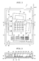
- FIG. 1 is a plan view of a QC phantom according to a first embodiment of the present invention and FIG. 2 is a cross-sectional view taken along the line A-A in FIG. 1.
- a QC phantom 1 shown in FIGs. 1 and 2 is used to perform verification of the performance and invariance of a CR system.
- a rectangular-shaped copper plate 12 is provided as a substrate in the bottom portion of a box-shaped frame member 11. This copper plate 12 gives mechanical stability to the QC phantom 1 and imparts X-ray beam quality appropriate for image analysis.
- a top plate 16 serving as a protection plate is fixed to an opening portion of the frame member 11 so that this opening portion is closed. Also, disposed in the frame member 11 are a Burger pattern 20 for visually evaluating the low contrast resolution of an image, an edge pattern 30 for quantitatively evaluating the sharpness of the image, a wire mesh pattern 40 for visually evaluating the sharpness of the image, a step-shaped pattern 50 for visually evaluating and quantitatively evaluating the linearity and dynamic range of the image, and a scale pattern 60 for quantitatively evaluating the scale factor of the image.
- narrow and long protrusions 14 for positioning the QC phantom 1 with respect to a cassette or a stimulable phosphor sheet are respectively provided for both the end sides on the underside of the frame member 11, and concave-shaped handgrip portions 15 for facilitating carrying of the QC phantom 1 are respectively formed at the center in the lower portions of both the sides of the frame member 11.
- the positioning of the QC phantom 1 with respect to a cassette or a stimulable phosphor sheet is performed through fitting of the protrusions 14 into concave-shaped receiving portions provided in the cassette or the stimulable phosphor sheet. In the case of a cassette that is larger than the QC phantom 1, however, the positioning is performed through matching of the external shape of the QC phantom 1.
- a substantially square resin plate 13 is provided as a substrate in the center portion of the copper plate 12.
- the Burger pattern 20 includes 16 step portions 21a to 21d, 22a to 22d, 23a to 23d, and 24a to 24d that are each made of an acrylic resin or the like and are welded and fixed on the resin plate 13 made of an acrylic resin, for instance. These step portions 21a to 21d, 22a to 22d, 23a to 23d, and 24a to 24d are arranged in a matrix manner so as to differ in their thicknesses in an X direction and differ in their sizes in a Y direction. With the Burger pattern 20 having such a construction, the low contrast resolution of an image is visually evaluated and the relative contrast and S/N ratio of a radiation imaging system are verified.
- a welding agent such as methylene chloride
- methylene chloride is applied to predetermined locations of the Burger pattern 20 and/or the resin plate 13 and are rapidly solidified.
- the use of such a welding agent makes it possible to prevent capturing of the welding agent into an X-ray image and to realize strong bonding and fixation without using structural members such as screws.
- the attachment or fixation of the resin plate 13 to or on the copper plate 12 Due consideration is given to the attachment or fixation of the resin plate 13 to or on the copper plate 12 to prevent a difference in coefficient of thermal expansion between the two plates from affecting the attachment or fixation.
- the state of attachment or fixation is not shown, for instance, the edge portion of one side of the resin plate 13 may only be bonded to the copper plate 12 to reduce any influence of the difference in coefficient of thermal expansion, or a region of the resin plate 13 which is apart from the image quality evaluation patterns and hence does not affect the image quality evaluation may be screwed onto the copper plate 12.
- the attachment or fixation can also be made by bonding the bonding surface of the resin plate 13 to the copper plate 12 using an elastic bonding agent.
- an elastic bonding agent can be used in the entire bonding surface of the resin plate 13 for bonding to the copper plate 12, but the elastic bonding agent is expensive and its use in the entire surface is not preferable from a cost standpoint. It is therefore preferable to use a bonding agent in a part of the bonding surface if the resin plate 13 can be attached to or fixed on the copper plate 12.
- the edge pattern 30, the wire mesh pattern 40, the step-shaped pattern 50, and the scale pattern 60 are each fixed at a predetermined position on the copper plate 12 using a bonding agent.
- a bonding agent is used. This is because the metal-based image quality evaluation patterns are relatively high in X-ray absorption factor, so that a high contrast X-ray image is obtained, making those patterns less susceptible to the influence of capturing of the bonding agent into the image. With this construction, it becomes possible to obtain a strong bonding strength without using structural members such as screws.
- the edge pattern 30 is used as a reference for geometric measurement and has sharp angular edge portions 31 and 32 for MTF measurement in different directions.
- These angular edge portions 31 and 32 are each made of a tungsten plate and are provided with lead plates 81 and 82 on the outside thereof, respectively, so that the major portion of X-ray propagation therethrough is inhibited.
- the MTF described above is obtained by differentiating the X-ray image of the edge pattern 30, obtaining a line spread function, and performing Fourier transform.
- the wire mesh pattern 40 is a mesh made of steel.
- This wire mesh pattern 40 includes four mesh portions 41 to 44 having different sizes and enables a visual evaluation of the resolution (sharpness) of the CR system. It is possible to evaluate the resolution of the CR system through comparison of visibilities among the multiple mesh portions 41 to 44.
- the wire mesh pattern 40 includes the four mesh portions 41 to 44, thereby improving the accuracy of a resolution evaluation.
- step-shaped pattern 50 four rectangular-shaped copper plates 51 to 54 having different thicknesses are arranged in a step manner in the Y direction and are used to perform a visual evaluation and a quantitative evaluation of the linearity and dynamic range of an X-ray image.
- the intensity of X-rays passing through the copper plates 51 to 54 are in inverse proportion to their thicknesses, so that it is possible to realize intensity levels ranging from the maximum intensity to the minimum intensity using the respective copper plates 51 to 54.
- the step-shaped pattern 50 includes the four copper plates 51 to 54 in this embodiment, the pattern 50 is not limited to this and may be constructed using copper plates having various sizes and thicknesses.
- the scale pattern 60 includes a main scale 61 made of copper and provided so as to extend in the X direction and an auxiliary scale 62 made of copper and provided so as to extend in the Y direction, and is used to evaluate the scale factor of an image.
- reference numerals 71, 72, and 73 each denote a marker used to perform alignment of the QC phantom 1 and to detect the positions of the various patterns. These markers are respectively provided in the corner portions of the copper plate 12 and facilitate automated processing at the time of computer processing of an image by enabling automatic detection of an error in installation direction to the cassette and confirmation of the positions of the various patterns.
- reference numeral 90 represents a serial label on which a serial number has been printed.
- a coefficient of linear expansion ⁇ p of each of corresponding image quality evaluation patterns which are fixed to each substrate and a coefficient of linear expansion ⁇ s of each substrate to which the corresponding image quality evaluation patterns are fixed must be satisfied in a relation of
- the coefficient of linear expansion ⁇ p of each of the corresponding image quality evaluation patterns and the coefficient of linear expansion ⁇ s of each substrates are satisfied in a relation of
- the QC phantom 1 has a construction where the edge pattern 30, the wire mesh pattern 40, the step-shaped pattern 50, and the scale pattern 60 that are each an image quality evaluation pattern made of a metal are fixed on the copper plate 12 serving as a substrate and the Burger pattern 20 made of a resin is welded onto the resin plate 13 that is another substrate.
- FIG. 3 is a plan view of the QC phantom according to the second embodiment of the present invention and FIG. 4 is a cross-sectional view taken along the line B-B in FIG. 3.
- a QC phantom 100 shown in FIGs. 3 and 4 has a frame member 110 formed by combining upper and lower frames 111 with side frames 112 into a rectangular shape.
- a supporting plate 113 made of an acrylic resin and a top plate 114 also made of an acrylic resin are placed parallel to each other while being spaced apart from each other in the vertical direction (thickness direction of the frame member 110).
- one pair of upper and lower annular grooves 110a are formed in the inner peripheral surface of the frame member 110 at positions slightly inside from the upper and lower ends thereof.
- a copper plate 115 is provided as a substrate and the peripheral ends of the supporting plate 113, the copper plate 115, and the top plate 114 are fitted into the annular grooves 110a.
- the peripheral ends of the supporting plate 113, the copper plate 115, and the top plate 114 are only partially fixed to the annular grooves 110a so that it is possible to absorb distortion due to differences in the coefficient of thermal expansion among the frame member 110, the supporting plate 113, the copper plate 115, and the top plate 114.
- an edge pattern 30 made of tungsten and having angular edge portions 31 and 32 for MTF measurement in different directions which are surrounded by lead plates 81 and 82 on the outside thereof, respectively, so that the major portion of X-ray propagation therethrough is inhibited
- a wire mesh pattern 40 including four mesh portions 41 to 44 made of steel and having different sizes
- a step-shaped pattern 50 in which four rectangular-shaped copper plates 51 to 54 having different thicknesses are arranged in a step manner in a Y direction
- a scale pattern 60 including a main scale 61 made of copper and provided so as to extend in an X direction and an auxiliary scale 62 made of copper and provided so as to extend in the Y direction
- markers 71, 72, and 73 respectively provided in the corner portions of the copper plate 115.
- a Burger pattern 20 made of an acrylic resin is welded in the center portion of the top plate 114.
- This Burger phantom 20 includes 16 step portions 21a to 21d, 22a to 22d, 23a to 23d, and 24a to 24d, with these step portions 21a to 21d, 22a to 22d, 23a to 23d, and 24a to 24d being arranged in a matrix manner so as to differ in their thicknesses in the X direction and differ in their sizes in the Y direction.
- a display member 120 for displaying the sizes and thicknesses of the step portions 21a to 24d of the Burger pattern 20 and a display member 130 for displaying the mesh sizes of the mesh portions 41 to 44 are provided between the top plate 114 and the copper plate 115, with these display members 120 and 130 also serving as reinforcers of the QC phantom 100.
- these display members 120 and 130 also serving as reinforcers of the QC phantom 100.
- the QC phantom 100 has a construction in which the multiple image quality evaluation patterns are disposed in a hollow portion defined by the frame member 110, the supporting plate 113, and the top plate 114.
- the Burger pattern 20 is fixed to the top plate 114.
- the supporting plate 113 and the top plate 114 are positioned inside the top and bottom ends of the frame member 110. With this construction, the phantom main body is prevented from directly contacting a cassette or a stimulable phosphor sheet. As a result, it becomes possible to suppress damage to the QC phantom 100, the cassette, and the stimulable phosphor sheet.
- each image quality evaluation pattern is fixed to a substrate made of the same material as the material forming the image quality evaluation pattern.
- image quality evaluation patterns made of metals such as the edge pattern 30, wire mesh pattern 40, step-shaped pattern 50 and scale pattern 60 are used for the image quality evaluation patterns to be fixed on the copper plate 12 or 115 serving as the substrate.
- the Burger pattern 20 made of a resin is used for the image quality evaluation pattern fixed on the resin plate 13 or the top plate 114 made of a resin that is another substrate.
- the image quality evaluation patterns may be produced using materials having high radiation absorption rates instead of the image quality evaluation patterns made of metals, or the Burger pattern 20 may de produced by using a material having a low radiation absorption rate instead of the Burger pattern 20 made of a resin.
- the material of the Burger pattern 20 is not limited to resins but a material having a relatively low radiation absorption rate such as ceramic may be used for its production.
- FIG. 5 is a block diagram of a CR system that photographs the QC phantom 1, 100 described above.
- the CR system 200 shown in FIG. 5 includes an imaging section 201 for photographing the QC phantom 1, 100 as a subject and obtaining an image thereof, an image reading means 202 for reading image data of the obtained image, a console 203 for performing processing on the read image data, performing evaluation computation for quantitative evaluation of the image, and outputting additional information concerning the image, and display means 204 for displaying the image of the QC phantom 1, 100 together with the additional information.
- the imaging section 201 has an X-ray source 201a, which projects X rays onto the QC phantom 1, 100, and a recording medium, such as a stimulable phosphor sheet 201b, on which X rays having passed through the QC phantom 1, 100 are to be recorded.
- a recording medium such as a stimulable phosphor sheet 201b, on which X rays having passed through the QC phantom 1, 100 are to be recorded.
- the image reading means 202 irradiates excitation light onto the stimulable phosphor sheet 201b, on which an X-ray image has been recorded, and reads photostimulated luminescence light generated from the stimulable phosphor sheet 201b, thereby reading data of the image photographed on the stimulable phosphor sheet 201b.
- the image reading means 202 is a reading head that uses a line light source produced by arranging excitation light sources, such as LEDs, in a main scanning direction as a light source of the excitation light and has a line sensor, such as a line CCD, provided so as to extend in the main scanning direction.
- the excitation light emitted from the line light source is made incident on the stimulable phosphor sheet 201b and photostimulated luminescence light generated from the stimulable phosphor sheet 201b is read using the line sensor.
- the image reading means 202 uses a laser beam as the excitation light and deflects the laser beam in the main scanning direction so that the laser beam is incident on the stimulable phosphor sheet 201b.
- the stimulable phosphor sheet 201b is conveyed in the auxiliary scanning direction, thereby two-dimensionally scanning the stimulable phosphor sheet 201b with the excitation light.
- the photostimulated luminescence light generated in this manner is propagated by a light-propagating device and is detected using a photodetector, such as a photomultiplier, and an AD converter, thereby reading the data of the image photographed on the stimulable phosphor sheet 201b.
- the console 203 is constructed using a personal computer (PC), for instance, and is connected to the image reading means 202 and the display means 204 through known communication means such as a computer communication network. Also, the console 203 includes an image processing portion 203a for performing image processing of the image data read by the image reading means 202, a QC tool 203b that performs a quantitative evaluation (QC computation) of the image, and an additional information storage portion 203c for recording additional information concerning the image.
- PC personal computer
- the QC tool 203b is provided with software for quantitatively evaluating images of the various image quality evaluation patterns of the QC phantom 1, 100.
- the QC tool 203 receives an image of the QC phantom 1, 100 processed by the image processing portion 203a, performs a quantitative evaluation of images of the various image quality evaluation patterns, and displays a result of the evaluation using the display means 204. Also, when a visual evaluation is performed, the images are displayed using the display means 204.
- the quantitative evaluation software has various signal processing algorithms, with these algorithms having every logic means for calculating required quality measurement of the radiation imaging system 200 when applied to the images of the various image quality evaluation patterns of the QC phantom 1, 100.
- the QC tool 203b is incorporated into the console 203 in this embodiment, but this is not the sole case of the present invention.
- This tool 203b may be incorporated into a host computer managing the whole of the system, for instance.
- a PC on which only the QC tool 203b is installed, may be used.
- the additional information storage portion 203c stores: imaging conditions used at the time of X-ray photographing such as an X-ray tube voltage and a distance between an X-ray source and a subject; image reading conditions used in the image reading means 202; image processing conditions used in the image processing portion 203a; and image display conditions used in the display means 204 such as the number of pixels, the number of steps of gradation, and the presence or absence of image processing. This additional information is read out to the QC tool 203b as necessary.
- the display means 204 includes a printer 204a, such as a laser printer, and a display 204b such as a CRT display or a liquid crystal display. With this construction, the display means 204 outputs the image of the QC phantom 1, 100 and the additional information as a visible image.
- a printer 204a such as a laser printer
- a display 204b such as a CRT display or a liquid crystal display.
- the QC phantom 1, 100 is placed between the X-ray source 201a and the stimulable phosphor sheet 201b, and X rays are projected from the X-ray source 201a.
- the intensities are attenuated and inhibited by the various image quality evaluation patterns constituting the QC phantom 1, 100.
- the intensities are converted into various spatial values and are recorded on the stimulable phosphor sheet 201b.
- the X-ray intensities recorded on the stimulable phosphor sheet 201b are read by the image reading means 202.
- the image reading means 202 irradiates the stimulable phosphor sheet 201b with a laser beam, thereby converting the recorded X-ray intensity into photostimulated luminescence light.
- the photostimulated luminescence light is read as digital image data using a photodetector and the digital data is recorded on an information recording medium.
- the image processing portion 203a performs image processing, such as gradation processing, on read image data of the image quality evaluation patterns. Then, the QC tool 203b quantitatively evaluates the processed image based on various image quality evaluation items. When doing so, if necessary, some of the additional information is read out from the additional information storage portion 203c and is applied to the QC computation. Also, the image is visually evaluated through printing on a film by the printer 204a or displaying on the display 204b. That is, through the quantitative evaluation and visual evaluation of the images of the various image quality evaluation patterns of the QC phantom 1, 100, the performance and invariance of the CR system 200 are verified.
- image processing such as gradation processing
- each image quality evaluation pattern is fixed to a substrate through welding or bonding.
- the image quality evaluation pattern may be integrally molded with the substrate or formed through cutting by an NC machine tool or the like.
- the QC phantom 1, 100 of the present invention is usable not only in the CR system described above but also in a CR system that uses a flat panel detector (FPD).
- FPD flat panel detector
- the coefficients of linear expansion ⁇ p of the various image quality evaluation patterns and the coefficient of linear expansion ⁇ s of the substrate, to which the image quality evaluation patterns are fixed satisfy a relation of "
Landscapes
- Health & Medical Sciences (AREA)
- Life Sciences & Earth Sciences (AREA)
- Medical Informatics (AREA)
- Engineering & Computer Science (AREA)
- Radiology & Medical Imaging (AREA)
- Molecular Biology (AREA)
- Biophysics (AREA)
- Nuclear Medicine, Radiotherapy & Molecular Imaging (AREA)
- Optics & Photonics (AREA)
- Pathology (AREA)
- Physics & Mathematics (AREA)
- Biomedical Technology (AREA)
- Heart & Thoracic Surgery (AREA)
- High Energy & Nuclear Physics (AREA)
- Surgery (AREA)
- Animal Behavior & Ethology (AREA)
- General Health & Medical Sciences (AREA)
- Public Health (AREA)
- Veterinary Medicine (AREA)
- Apparatus For Radiation Diagnosis (AREA)
- Measurement Of Radiation (AREA)
Abstract
Description
- The present invention relates to a phantom for quality control or QC phantom used to perform quality assurance of a radiation imaging system that uses radiation or in particular X-rays.
- Digital radiography (DR) or in particular a digital radiation imaging system (hereinafter referred to as the "computed radiography (CR) system") that uses a photostimulable phosphor has been more and more widely used as a method replacing conventionally used radiography based on an intensifying screen and a silver salt film.
- In this CR system, radiation that has passed through or has been emitted from a subject is absorbed into a radiation image conversion panel containing a photostimulable phosphor, the absorbed energy is emitted as fluorescence through excitation of the panel using excitation light such as infrared rays, and this fluorescence is read as a digital image through conversion into an electric signal.
- With such a CR system, it is possible to obtain a digital image having an abundant amount of information, so that it is possible to carry out sophisticated medical diagnosis, for instance. In addition, it is also possible to transmit/receive the digital image as digital data, so that this system is also effective in remote medical care or the like.
- By the way, in order to assure use of an X-ray image with a high degree of reliability, it is required to measure and verify the performance of the CR system. If image quality of the CR system is low, high-reliability image analysis is impossible. This is because an image that is low in reliability and unusable is generated owing to lowering of image contrast quality, for instance.
- In order to solve this problem, measurement of parameters of the CR system is performed using a QC phantom. This QC phantom includes various image quality evaluation patterns fixed on a substrate. Those image quality evaluation patterns have characteristics such as sizes, shapes, densities, and compositions, are formed using various materials, are designed so that one or more image quality evaluation items of the CR system can be measured, and are set so that an invariance evaluation of different performance parameters of the CR system can be performed.
- That is, first, the QC phantom is irradiated between a radiation source and a radiation image conversion panel. Then, image reading is performed, thereby obtaining a digital image in which the image quality evaluation patterns are captured, and a reproduction image thereof. Following this, a quantitative or visual image evaluation is performed, thereby performing a performance evaluation/image evaluation.
- As examples of such a QC phantom, there are known a QC phantom disclosed in JP 01-148241 A that protects a resolving power chart made of tungsten in a methacrylic resin and a QC phantom disclosed in JP 2001-299736 A that uses a photoetching metal that is considered to have less distortion due to heat.
- When image quality evaluation patterns made of metallic materials are fixed in a resin like in the case of the QC phantom disclosed in JP 01-148241 A, however, cracking may occur to the image quality evaluation patterns owing to differences in coefficient of thermal expansion between the metals and the resin.
- Also, when resin patterns are fixed on a metal, for instance, this results in a situation where even if the coefficient of thermal expansion of the metal itself is small, peeling tends to occur owing to differences in coefficient of thermal expansion between the metal and the resins.
- It is of course possible to fix the image quality evaluation patterns using structural members such as screws in order to increase fixation strength. In this case, however, such structural members are also captured at the time of X-ray imaging and therefore this construction is not appropriate.
- The present invention has been made in view of the circumstances described above, and an object of the present invention is to provide a QC phantom that is capable of preventing cracking and peeling of image quality evaluation patterns with reliability and obtaining an X-ray image where no construction members other than the image quality evaluation patterns are captured.
- It should be noted here that the above object and other objects as well as novel features of the present invention will become apparent from the following description to be made with reference to the accompanying drawings.
- In order to achieve the above object, the present invention provides a phantom for quality control used to perform verification of performance and invariance of a radiation imaging system, comprising:
- substrates; and
- image quality evaluation patterns fixed to the substrates, the image quality evaluation patterns being photographed with the radiation imaging system and pattern images obtained by photographing the image quality evaluation patterns being evaluated based on image quality evaluation items, wherein a coefficient of linear expansion αp of each of corresponding image quality evaluation patterns which are fixed to each of the substrates and a coefficient of linear expansion αs of each of the substrates to which the corresponding image quality evaluation patterns are fixed, are in a relation of
-
- The coefficient of linear expansion αp of each of the corresponding image quality evaluation patterns and the coefficient of linear expansion αs of each of the substrates are preferably in a relation of
- The coefficient of linear expansion αp of each of the corresponding image quality evaluation patterns and the coefficient of linear expansion αs of each of the substrates are more preferably in a relation of
- The image quality evaluation patterns are preferably fixed to the substrates by welding or bonding an image quality evaluation pattern on a substrate, alternatively, by molding integrally the image quality evaluation pattern with the substrate or forming the image quality evaluation pattern and the substrate through cutting by an NC machine tool.
- The applicant proposes a QC phantom which has patterns made of different materials including an edge pattern or the like for use in sharpness measurement being made of a metal and a Burger pattern or the like for use in relative contrast measurement being made of a resin, and which is capable of many kinds of image quality evaluations upon being once photographed.
- The present invention is particularly effective in this case.
- In the phantom for quality control according to the present invention, the image quality evaluation patterns comprises first image quality evaluation patterns each made of a material or materials having a high radiation absorption rate; and second image quality evaluation patterns each made of a material or materials having a low radiation absorption rate.
- Preferably, the first image quality evaluation patterns are made of a metal or metals and the second image quality evaluation patterns are made of a resin or resins.
- It is preferred that the phantom for quality control of the present invention further comprises a rectangular frame member having a hollow portion; the substrates includes a first rectangular substrate made of a metal and provided in the hollow portion of the rectangular frame member and a rectangular top plate made of a resin and placed in the hollow portion of the rectangular frame member to oppose the first rectangular substrate with a preset distance between the rectangular top plate and the first rectangular substrate, the rectangular top plate serving as a second substrate; and that, in a hollow space formed by the rectangular frame member, the first rectangular substrate and the rectangular top plate, the first image quality evaluation patterns are fixed to an upper surface of the first rectangular substrate and the second image quality evaluation patterns are fixed to a lower surface of the rectangular top plate.
- Preferably, peripheral ends of the first rectangular substrate and the rectangular top plate are partially fixed to the rectangular frame member under a state where the peripheral ends are fitted into an inner peripheral portion of the rectangular frame member.
- The first rectangular substrate and the rectangular top plate are preferably disposed on an inside in a thickness direction of the rectangular frame member.
- It is preferred that the phantom for quality control of the present invention further comprises a supporting plate for supporting the first rectangular substrate, the supporting plate is made of a resin and placed in the hollow portion of the rectangular frame member to oppose the first rectangular substrate, and that the first rectangular substrate is mounted on the supporting plate.
- It is preferred that the phantom for quality control of the present invention further comprises a box-shaped frame member having an opening portion; the substrates includes a first rectangular substrate made of a metal and provided in the opening portion of the box-shaped frame member and a second rectangular substrate made of a resin and provided in a center portion of the first rectangular substrate; and that the first image quality evaluation patterns are fixed to an upper surface of the first rectangular substrate and the second image quality evaluation patterns are fixed to an upper surface of the second rectangular substrate.
- The first rectangular substrate is preferably provided in a bottom portion of the box-shaped frame member.
- It is preferred that the phantom for quality control of the present invention further comprises a rectangular top plate made of a resin and fixed to the opening portion of the box-shaped frame member so that the opening portion is closed, and that the rectangular top plate serves as a protection plate.
- The first rectangular substrate and the rectangular top plate are preferably disposed on an inside with a preset distance in a thickness direction of the box-shaped frame member.
- In the accompanying drawings:
- FIG. 1 is a plan view of a QC phantom according to a first embodiment of the present invention;
- FIG. 2 is a cross-sectional view taken along the line A-A in FIG. 1;
- FIG. 3 is a plan view of a QC phantom according to a second embodiment of the present invention;
- FIG. 4 is a cross-sectional view taken along the line B-B in FIG. 3; and
- FIG. 5 is a block diagram of a CR system having the QC phantom shown in FIG. 1 or 3.
-
- The QC phantom of the present invention will now be described in detail with reference to embodiments showing in the accompanying drawings.
- FIG. 1 is a plan view of a QC phantom according to a first embodiment of the present invention and FIG. 2 is a cross-sectional view taken along the line A-A in FIG. 1.
- A
QC phantom 1 shown in FIGs. 1 and 2 is used to perform verification of the performance and invariance of a CR system. In theQC phantom 1, a rectangular-shaped copper plate 12 is provided as a substrate in the bottom portion of a box-shaped frame member 11. Thiscopper plate 12 gives mechanical stability to theQC phantom 1 and imparts X-ray beam quality appropriate for image analysis. - A
top plate 16 serving as a protection plate is fixed to an opening portion of theframe member 11 so that this opening portion is closed. Also, disposed in theframe member 11 are aBurger pattern 20 for visually evaluating the low contrast resolution of an image, anedge pattern 30 for quantitatively evaluating the sharpness of the image, awire mesh pattern 40 for visually evaluating the sharpness of the image, a step-shaped pattern 50 for visually evaluating and quantitatively evaluating the linearity and dynamic range of the image, and ascale pattern 60 for quantitatively evaluating the scale factor of the image. - Further, narrow and
long protrusions 14 for positioning theQC phantom 1 with respect to a cassette or a stimulable phosphor sheet are respectively provided for both the end sides on the underside of theframe member 11, and concave-shaped handgrip portions 15 for facilitating carrying of theQC phantom 1 are respectively formed at the center in the lower portions of both the sides of theframe member 11. Note that the positioning of theQC phantom 1 with respect to a cassette or a stimulable phosphor sheet is performed through fitting of theprotrusions 14 into concave-shaped receiving portions provided in the cassette or the stimulable phosphor sheet. In the case of a cassette that is larger than theQC phantom 1, however, the positioning is performed through matching of the external shape of theQC phantom 1. - A substantially
square resin plate 13 is provided as a substrate in the center portion of thecopper plate 12. TheBurger pattern 20 includes 16step portions 21a to 21d, 22a to 22d, 23a to 23d, and 24a to 24d that are each made of an acrylic resin or the like and are welded and fixed on theresin plate 13 made of an acrylic resin, for instance. Thesestep portions 21a to 21d, 22a to 22d, 23a to 23d, and 24a to 24d are arranged in a matrix manner so as to differ in their thicknesses in an X direction and differ in their sizes in a Y direction. With theBurger pattern 20 having such a construction, the low contrast resolution of an image is visually evaluated and the relative contrast and S/N ratio of a radiation imaging system are verified. - It should be noted here that at the time of welding of the
Burger pattern 20 onto theresin plate 13, a welding agent, such as methylene chloride, is applied to predetermined locations of theBurger pattern 20 and/or theresin plate 13 and are rapidly solidified. The use of such a welding agent makes it possible to prevent capturing of the welding agent into an X-ray image and to realize strong bonding and fixation without using structural members such as screws. - Due consideration is given to the attachment or fixation of the
resin plate 13 to or on thecopper plate 12 to prevent a difference in coefficient of thermal expansion between the two plates from affecting the attachment or fixation. Although the state of attachment or fixation is not shown, for instance, the edge portion of one side of theresin plate 13 may only be bonded to thecopper plate 12 to reduce any influence of the difference in coefficient of thermal expansion, or a region of theresin plate 13 which is apart from the image quality evaluation patterns and hence does not affect the image quality evaluation may be screwed onto thecopper plate 12. Alternatively, the attachment or fixation can also be made by bonding the bonding surface of theresin plate 13 to thecopper plate 12 using an elastic bonding agent. In this case, an elastic bonding agent can be used in the entire bonding surface of theresin plate 13 for bonding to thecopper plate 12, but the elastic bonding agent is expensive and its use in the entire surface is not preferable from a cost standpoint. It is therefore preferable to use a bonding agent in a part of the bonding surface if theresin plate 13 can be attached to or fixed on thecopper plate 12. - Also, the
edge pattern 30, thewire mesh pattern 40, the step-shapedpattern 50, and thescale pattern 60 are each fixed at a predetermined position on thecopper plate 12 using a bonding agent. Note that when such metal-based image quality evaluation patterns are fixed to thecopper plate 12 serving as a substrate, a bonding agent is used. This is because the metal-based image quality evaluation patterns are relatively high in X-ray absorption factor, so that a high contrast X-ray image is obtained, making those patterns less susceptible to the influence of capturing of the bonding agent into the image. With this construction, it becomes possible to obtain a strong bonding strength without using structural members such as screws. - The
edge pattern 30 is used as a reference for geometric measurement and has sharpangular edge portions angular edge portions lead plates edge pattern 30, obtaining a line spread function, and performing Fourier transform. - It is preferable that the
wire mesh pattern 40 is a mesh made of steel. Thiswire mesh pattern 40 includes fourmesh portions 41 to 44 having different sizes and enables a visual evaluation of the resolution (sharpness) of the CR system. It is possible to evaluate the resolution of the CR system through comparison of visibilities among themultiple mesh portions 41 to 44. - In this embodiment, the
wire mesh pattern 40 includes the fourmesh portions 41 to 44, thereby improving the accuracy of a resolution evaluation. However, it is also possible to perform more precise evaluation using five or more mesh portions having different sizes. Note that the sizes, thicknesses, and arrangement intervals of such meshes are not specifically limited and may be set at appropriate values. - In the step-shaped
pattern 50, four rectangular-shapedcopper plates 51 to 54 having different thicknesses are arranged in a step manner in the Y direction and are used to perform a visual evaluation and a quantitative evaluation of the linearity and dynamic range of an X-ray image. The intensity of X-rays passing through thecopper plates 51 to 54 are in inverse proportion to their thicknesses, so that it is possible to realize intensity levels ranging from the maximum intensity to the minimum intensity using therespective copper plates 51 to 54. While the step-shapedpattern 50 includes the fourcopper plates 51 to 54 in this embodiment, thepattern 50 is not limited to this and may be constructed using copper plates having various sizes and thicknesses. - The
scale pattern 60 includes amain scale 61 made of copper and provided so as to extend in the X direction and anauxiliary scale 62 made of copper and provided so as to extend in the Y direction, and is used to evaluate the scale factor of an image. Note that in FIG. 1,reference numerals QC phantom 1 and to detect the positions of the various patterns. These markers are respectively provided in the corner portions of thecopper plate 12 and facilitate automated processing at the time of computer processing of an image by enabling automatic detection of an error in installation direction to the cassette and confirmation of the positions of the various patterns. Also,reference numeral 90 represents a serial label on which a serial number has been printed. - Here, in the QC phantom of the present invention, a coefficient of linear expansion αp of each of corresponding image quality evaluation patterns which are fixed to each substrate and a coefficient of linear expansion αs of each substrate to which the corresponding image quality evaluation patterns are fixed, must be satisfied in a relation of |αp-αs|≦5×10⁻⁵.
- The coefficient of linear expansion α(K-1) is represented by the following equation:
- Table 1 below shows α values of materials very often used in the QC phantom.
Material Coefficient of linear expansion α ( K-1) Copper 1.65 x 10⁻⁵ Aluminum 2.31 × 10⁻⁵ Tungsten 0.45 x 10⁻⁵ Stainless steel 1.47 x 10⁻⁵ Lead 2.89 x 10⁻⁵ Acrylic resin 7 x 10⁻⁵ Polymethyl methacrylate 8 x 10⁻⁵ - It is preferable that the coefficient of linear expansion αp of each of the corresponding image quality evaluation patterns and the coefficient of linear expansion αs of each substrates are satisfied in a relation of |αp-αs| ≦2.5x10⁻⁵ more preferably, |αp-αs|≦1.5×10⁻⁵.
- The
QC phantom 1 has a construction where theedge pattern 30, thewire mesh pattern 40, the step-shapedpattern 50, and thescale pattern 60 that are each an image quality evaluation pattern made of a metal are fixed on thecopper plate 12 serving as a substrate and theBurger pattern 20 made of a resin is welded onto theresin plate 13 that is another substrate. With this construction in which the image quality evaluation pattern and the substrate are satisfied in the above relation of |αp-αs|≦ 5×10⁻⁵, it becomes possible to prevent cracking and peeling of the image quality evaluation patterns due to differences in coefficient of thermal expansion and to suppress capturing of construction members other than the image quality evaluation patterns into an X-ray image. - Next, a QC phantom according to a second embodiment of the present invention will be described by giving the same reference numerals to the same construction members as those of FIGs. 1 and 2. Note that FIG. 3 is a plan view of the QC phantom according to the second embodiment of the present invention and FIG. 4 is a cross-sectional view taken along the line B-B in FIG. 3.
- A
QC phantom 100 shown in FIGs. 3 and 4 has aframe member 110 formed by combining upper andlower frames 111 withside frames 112 into a rectangular shape. In thisframe member 110, a supportingplate 113 made of an acrylic resin and atop plate 114 also made of an acrylic resin are placed parallel to each other while being spaced apart from each other in the vertical direction (thickness direction of the frame member 110). Also, one pair of upper and lowerannular grooves 110a are formed in the inner peripheral surface of theframe member 110 at positions slightly inside from the upper and lower ends thereof. - On the supporting
plate 113, acopper plate 115 is provided as a substrate and the peripheral ends of the supportingplate 113, thecopper plate 115, and thetop plate 114 are fitted into theannular grooves 110a. Here, the peripheral ends of the supportingplate 113, thecopper plate 115, and thetop plate 114 are only partially fixed to theannular grooves 110a so that it is possible to absorb distortion due to differences in the coefficient of thermal expansion among theframe member 110, the supportingplate 113, thecopper plate 115, and thetop plate 114. - Disposed at predetermined positions on the
copper plate 115 are anedge pattern 30 made of tungsten and havingangular edge portions lead plates wire mesh pattern 40 including fourmesh portions 41 to 44 made of steel and having different sizes, a step-shapedpattern 50 in which four rectangular-shapedcopper plates 51 to 54 having different thicknesses are arranged in a step manner in a Y direction, ascale pattern 60 including amain scale 61 made of copper and provided so as to extend in an X direction and anauxiliary scale 62 made of copper and provided so as to extend in the Y direction, andmarkers copper plate 115. Note that when such metal-based image quality evaluation patterns are fixed to thecopper plate 115 that is a substrate, a bonding agent is used. With this construction, strong fixation is achieved without using structural members such as screws. Also, the reason why it is possible to perform the fixation using the bonding agent is that as described above, with the metal-based image quality evaluation patterns having a relatively high X-ray absorption factor, a high contrast X-ray image is obtained, making those patterns less susceptible to the influence of capturing of the bonding agent into the image. - A
Burger pattern 20 made of an acrylic resin is welded in the center portion of thetop plate 114. ThisBurger phantom 20 includes 16step portions 21a to 21d, 22a to 22d, 23a to 23d, and 24a to 24d, with thesestep portions 21a to 21d, 22a to 22d, 23a to 23d, and 24a to 24d being arranged in a matrix manner so as to differ in their thicknesses in the X direction and differ in their sizes in the Y direction. When theBurger pattern 20 is welded as described above, it becomes possible to suppress capturing of construction members other than theBurger pattern 20 into an X-ray image and to obtain a strong bonding strength. - A
display member 120 for displaying the sizes and thicknesses of thestep portions 21a to 24d of theBurger pattern 20 and adisplay member 130 for displaying the mesh sizes of themesh portions 41 to 44 are provided between thetop plate 114 and thecopper plate 115, with thesedisplay members QC phantom 100. Incidentally, if the thicknesses of thelead plates lead plates top plate 114, these plates also serve as reinforcers of theQC phantom 100. With this construction, it also becomes possible to prevent redundant capturing of dedicated reinforcers into an X-ray image. Also, aserial label 90 is stuck in the lower right corner portion of thetop plate 114. - As described above, the
QC phantom 100 has a construction in which the multiple image quality evaluation patterns are disposed in a hollow portion defined by theframe member 110, the supportingplate 113, and thetop plate 114. In particular, theBurger pattern 20 is fixed to thetop plate 114. With this construction, it becomes possible to reduce a dead space to a minimum level and to obtain a thin and lightweight phantom. Also, the supportingplate 113 and the top plate 114.are positioned inside the top and bottom ends of theframe member 110. With this construction, the phantom main body is prevented from directly contacting a cassette or a stimulable phosphor sheet. As a result, it becomes possible to suppress damage to theQC phantom 100, the cassette, and the stimulable phosphor sheet. - Also, as in the case of the
QC phantom 1, theedge pattern 30, thewire mesh pattern 40, the step-shapedpattern 50, and thescale pattern 60 that are each made of a metal are fixed on thecopper plate 115 serving as a substrate, and theBurger pattern 20 made of a resin is fixed to thetop plate 114 made of a resin that is another substrate. That is, each image quality evaluation pattern is fixed to a substrate made of the same material as the material forming the image quality evaluation pattern. With this construction, it becomes possible to prevent cracking and peeling of the image quality evaluation patterns due to differences in coefficient of thermal expansion and to firmly fix the image quality evaluation patterns to the substrates. Also, construction members other than the image quality evaluation patterns are not captured in an X-ray image and therefore the evaluation is not hindered. - In the above-mentioned
QC phantoms edge pattern 30,wire mesh pattern 40, step-shapedpattern 50 andscale pattern 60 are used for the image quality evaluation patterns to be fixed on thecopper plate Burger pattern 20 made of a resin is used for the image quality evaluation pattern fixed on theresin plate 13 or thetop plate 114 made of a resin that is another substrate. However, this is not the sole case of the present invention. The image quality evaluation patterns may be produced using materials having high radiation absorption rates instead of the image quality evaluation patterns made of metals, or theBurger pattern 20 may de produced by using a material having a low radiation absorption rate instead of theBurger pattern 20 made of a resin. To be more specific, the material of theBurger pattern 20 is not limited to resins but a material having a relatively low radiation absorption rate such as ceramic may be used for its production. - FIG. 5 is a block diagram of a CR system that photographs the
QC phantom - The
CR system 200 shown in FIG. 5 includes animaging section 201 for photographing theQC phantom console 203 for performing processing on the read image data, performing evaluation computation for quantitative evaluation of the image, and outputting additional information concerning the image, and display means 204 for displaying the image of theQC phantom - The
imaging section 201 has anX-ray source 201a, which projects X rays onto theQC phantom stimulable phosphor sheet 201b, on which X rays having passed through theQC phantom - The image reading means 202 irradiates excitation light onto the
stimulable phosphor sheet 201b, on which an X-ray image has been recorded, and reads photostimulated luminescence light generated from thestimulable phosphor sheet 201b, thereby reading data of the image photographed on thestimulable phosphor sheet 201b. For instance, the image reading means 202 is a reading head that uses a line light source produced by arranging excitation light sources, such as LEDs, in a main scanning direction as a light source of the excitation light and has a line sensor, such as a line CCD, provided so as to extend in the main scanning direction. With this construction, while the reading head and thestimulable phosphor sheet 201b are relatively moved in an auxiliary scanning direction orthogonal to the main scanning direction, the excitation light emitted from the line light source is made incident on thestimulable phosphor sheet 201b and photostimulated luminescence light generated from thestimulable phosphor sheet 201b is read using the line sensor. - Alternatively, the image reading means 202 uses a laser beam as the excitation light and deflects the laser beam in the main scanning direction so that the laser beam is incident on the
stimulable phosphor sheet 201b. When doing so, thestimulable phosphor sheet 201b is conveyed in the auxiliary scanning direction, thereby two-dimensionally scanning thestimulable phosphor sheet 201b with the excitation light. Then, the photostimulated luminescence light generated in this manner is propagated by a light-propagating device and is detected using a photodetector, such as a photomultiplier, and an AD converter, thereby reading the data of the image photographed on thestimulable phosphor sheet 201b. - The
console 203 is constructed using a personal computer (PC), for instance, and is connected to the image reading means 202 and the display means 204 through known communication means such as a computer communication network. Also, theconsole 203 includes animage processing portion 203a for performing image processing of the image data read by the image reading means 202, aQC tool 203b that performs a quantitative evaluation (QC computation) of the image, and an additionalinformation storage portion 203c for recording additional information concerning the image. - The
QC tool 203b is provided with software for quantitatively evaluating images of the various image quality evaluation patterns of theQC phantom QC tool 203 receives an image of theQC phantom image processing portion 203a, performs a quantitative evaluation of images of the various image quality evaluation patterns, and displays a result of the evaluation using the display means 204. Also, when a visual evaluation is performed, the images are displayed using the display means 204. Note that the quantitative evaluation software has various signal processing algorithms, with these algorithms having every logic means for calculating required quality measurement of theradiation imaging system 200 when applied to the images of the various image quality evaluation patterns of theQC phantom QC tool 203b is incorporated into theconsole 203 in this embodiment, but this is not the sole case of the present invention. Thistool 203b may be incorporated into a host computer managing the whole of the system, for instance. Also, a PC, on which only theQC tool 203b is installed, may be used. - The additional
information storage portion 203c stores: imaging conditions used at the time of X-ray photographing such as an X-ray tube voltage and a distance between an X-ray source and a subject; image reading conditions used in the image reading means 202; image processing conditions used in theimage processing portion 203a; and image display conditions used in the display means 204 such as the number of pixels, the number of steps of gradation, and the presence or absence of image processing. This additional information is read out to theQC tool 203b as necessary. - The display means 204 includes a
printer 204a, such as a laser printer, and adisplay 204b such as a CRT display or a liquid crystal display. With this construction, the display means 204 outputs the image of theQC phantom - At the time of imaging of the
QC phantom CR system 200 constructed in the manner described above, first, theQC phantom X-ray source 201a and thestimulable phosphor sheet 201b, and X rays are projected from theX-ray source 201a. When the X-rays pass through theQC phantom QC phantom stimulable phosphor sheet 201b. - Then, the X-ray intensities recorded on the
stimulable phosphor sheet 201b are read by the image reading means 202. For instance, the image reading means 202 irradiates thestimulable phosphor sheet 201b with a laser beam, thereby converting the recorded X-ray intensity into photostimulated luminescence light. Then, the photostimulated luminescence light is read as digital image data using a photodetector and the digital data is recorded on an information recording medium. - The
image processing portion 203a performs image processing, such as gradation processing, on read image data of the image quality evaluation patterns. Then, theQC tool 203b quantitatively evaluates the processed image based on various image quality evaluation items. When doing so, if necessary, some of the additional information is read out from the additionalinformation storage portion 203c and is applied to the QC computation. Also, the image is visually evaluated through printing on a film by theprinter 204a or displaying on thedisplay 204b. That is, through the quantitative evaluation and visual evaluation of the images of the various image quality evaluation patterns of theQC phantom CR system 200 are verified. - The QC phantom according to the present invention has been described in detail with reference to the embodiments, although the present invention is not limited to the QC phantoms described in the embodiments. It is possible to make various design changes without departing from the gist of the present invention described in the appended claims.
- For instance, in the embodiments described above, each image quality evaluation pattern is fixed to a substrate through welding or bonding. However, the image quality evaluation pattern may be integrally molded with the substrate or formed through cutting by an NC machine tool or the like.
- Also, the
QC phantom - Needless to say, in the embodiments described above, the coefficients of linear expansion αp of the various image quality evaluation patterns and the coefficient of linear expansion αs of the substrate, to which the image quality evaluation patterns are fixed, satisfy a relation of "|αp-αs| ≦5×10⁻⁵" .
- As can be understood from the above description, with the construction of the QC phantom of the present invention, it becomes possible to prevent cracking and peeling of the image quality evaluation patterns due to differences in coefficient of thermal expansion. Also, no construction members other than the image quality evaluation patterns are captured into an X-ray image, so that it becomes possible to perform a more accurate invariance test.
Claims (14)
- A phantom for quality control used to perform verification of performance and invariance of a radiation imaging system, comprising:wherein a coefficient of linear expansion αp of each of corresponding image quality evaluation patterns which are fixed to each of said substrates and a coefficient of linear expansion αs of each of said substrates to which said corresponding image quality evaluation patterns are fixed, are in a relation ofsubstrates; andimage quality evaluation patterns fixed to said substrates, said image quality evaluation patterns being photographed with said radiation imaging system and pattern images obtained by photographing said image quality evaluation patterns being evaluated based on image quality evaluation items,
- The phantom for quality control according to claim 1, wherein said coefficient of linear expansion αp of each of said corresponding image quality evaluation patterns and said coefficient of linear expansion αs of each of said substrates are in a relation of
- The phantom for quality control according to claim 1, wherein said coefficient of linear expansion αp of each of said corresponding image quality evaluation patterns and said coefficient of linear expansion αs of each of said substrates are in a relation of
- The phantom for quality control according to any one of claims 1 to 3, wherein said image quality evaluation patterns are fixed to said substrates by welding or bonding an image quality evaluation pattern on a substrate, alternatively, by molding integrally said image quality evaluation pattern with said substrate or forming said image quality evaluation pattern and said substrate through cutting by an NC machine tool.
- The phantom for quality control according to any one of claims 1 to 4, wherein said image quality evaluation patterns comprises:first image quality evaluation patterns each made of a material or materials having a high radiation absorption rate; andsecond image quality evaluation patterns each made of a material or materials having a low radiation absorption rate.
- The phantom for quality control according to claim 5, wherein said first image quality evaluation patterns are made of a metal or metals and said second image quality evaluation patterns are made of a resin or resins.
- The phantom for quality control according to claim 6, further comprising:wherein said substrates includes:a rectangular frame member having a hollow portion,wherein, in a hollow space formed by said rectangular frame member, said first rectangular substrate and said rectangular top plate, said first image quality evaluation patterns are fixed to an upper surface of said first rectangular substrate and said second image quality evaluation patterns are fixed to a lower surface of said rectangular top plate.a first rectangular substrate made of a metal and provided in said hollow portion of said rectangular frame member; anda rectangular top plate made of a resin and placed in said hollow portion of said rectangular frame member to oppose said first rectangular substrate with a preset distance between said rectangular top plate and said first rectangular substrate, said rectangular top plate serving as a second substrate,
- The phantom for quality control according to claim 7, wherein peripheral ends of said first rectangular substrate and said rectangular top plate are partially fixed to said rectangular frame member under a state where said peripheral ends are fitted into an inner peripheral portion of said rectangular frame member.
- The phantom for quality control according to claim 8, wherein said first rectangular substrate and said rectangular top plate are disposed on an inside in a thickness direction of said rectangular frame member.
- The phantom for quality control according to any one of claims 7 to 9, further comprising:wherein said supporting plate is made of a resin and placed in said hollow portion of said rectangular frame member to oppose said first rectangular substrate, anda supporting plate for supporting said first rectangular substrate,
wherein said first rectangular substrate is mounted on said supporting plate. - The phantom for quality control according to claim 6, further comprising:wherein said substrates includes:a box-shaped frame member having an opening portion,wherein said first image quality evaluation patterns are fixed to an upper surface of said first rectangular substrate and said second image quality evaluation patterns are fixed to an upper surface of said second rectangular substrate.a first rectangular substrate made of a metal and provided in said opening portion of said box-shaped frame member; anda second rectangular substrate made of a resin and provided in a center portion of said first rectangular substrate, and
- The phantom for quality control according to claim 11, wherein said first rectangular substrate is provided in a bottom portion of said box-shaped frame member.
- The phantom for quality control according to claim 11 or 12, further comprising:a rectangular top plate made of a resin and fixed to said opening portion of said box-shaped frame member so that said opening portion is closed, said rectangular top plate serving as a protection plate.
- The phantom for quality control according to claim 13, wherein said first rectangular substrate and said rectangular top plate are disposed on an inside with a preset distance in a thickness direction of said box-shaped frame member.
Applications Claiming Priority (2)
| Application Number | Priority Date | Filing Date | Title |
|---|---|---|---|
| JP2003158447A JP2004357868A (en) | 2003-06-03 | 2003-06-03 | Qc phantom |
| JP2003158447 | 2003-06-03 |
Publications (2)
| Publication Number | Publication Date |
|---|---|
| EP1484015A1 true EP1484015A1 (en) | 2004-12-08 |
| EP1484015B1 EP1484015B1 (en) | 2009-09-23 |
Family
ID=33157163
Family Applications (1)
| Application Number | Title | Priority Date | Filing Date |
|---|---|---|---|
| EP04013181A Expired - Lifetime EP1484015B1 (en) | 2003-06-03 | 2004-06-03 | Quality control phantom |
Country Status (4)
| Country | Link |
|---|---|
| US (1) | US7173238B2 (en) |
| EP (1) | EP1484015B1 (en) |
| JP (1) | JP2004357868A (en) |
| DE (1) | DE602004023251D1 (en) |
Cited By (5)
| Publication number | Priority date | Publication date | Assignee | Title |
|---|---|---|---|---|
| EP1741389A1 (en) * | 2005-07-06 | 2007-01-10 | Agfa-Gevaert | Method for cancelling the impact of the physical property variability on the image quality performance of a digital imaging system |
| EP1935340A1 (en) * | 2006-12-19 | 2008-06-25 | Agfa HealthCare NV | Method for neutralizing image artifacts prior to the determination of the Signal-to-noise ratio in CR/DR radiography systems |
| GB2449113A (en) * | 2007-05-11 | 2008-11-12 | Cameron Nigel Glenvi Carpenter | Apparatus For Measurement Accuracy Testing Of Radiological Imaging Modalities And Networked Digital Viewing Platforms |
| CN104997525A (en) * | 2015-06-10 | 2015-10-28 | 广州七喜医疗设备有限公司 | Apparatus and method for selecting key parts of digital radiographic image equipment |
| EP4359776A1 (en) * | 2021-06-23 | 2024-05-01 | Helmut Fischer GmbH Institut für Elektronik und Messtechnik | Measurement object and method for verifying a calibration of an x-ray fluorescence device |
Families Citing this family (21)
| Publication number | Priority date | Publication date | Assignee | Title |
|---|---|---|---|---|
| US6991371B2 (en) * | 2003-10-14 | 2006-01-31 | The Boeing Company | Computed tomography image quality phantom |
| US7344307B2 (en) * | 2004-11-12 | 2008-03-18 | General Electric Company | System and method for integration of a calibration target into a C-arm |
| EP1925254A1 (en) * | 2006-11-24 | 2008-05-28 | Ion Beam Applications S.A. | Method and device for quality management in a mammography apparatus |
| US8228570B2 (en) * | 2008-01-28 | 2012-07-24 | Air Techniques, Inc. | Process and apparatus for scanning imaged storage plates and having automatic gain adjustment |
| US20090268953A1 (en) * | 2008-04-24 | 2009-10-29 | Apteryx, Inc. | Method for the automatic adjustment of image parameter settings in an imaging system |
| US9720114B2 (en) * | 2008-06-25 | 2017-08-01 | Australian Nuclear Science And Technology Organization | Imaging test piece for medium and large security X-ray scanners |
| JP2010075317A (en) * | 2008-09-25 | 2010-04-08 | Fujifilm Corp | Stereo biopsy apparatus, method for controlling the same and phantom |
| US8308362B2 (en) | 2009-10-27 | 2012-11-13 | Dental Imaging Consultants, LLC | Quality assurance phantom for digital dental imaging and related method |
| JP5613925B2 (en) * | 2010-05-14 | 2014-10-29 | 国立大学法人群馬大学 | Multipurpose phantom and method of use |
| JP5826469B2 (en) * | 2010-07-30 | 2015-12-02 | 国立大学法人東北大学 | Evaluation aids |
| JP6030840B2 (en) * | 2012-03-13 | 2016-11-24 | 特定非営利活動法人日本乳がん検診精度管理中央機構 | Measuring instrument for performance evaluation of radiological diagnostic imaging equipment |
| US8708562B1 (en) | 2013-03-05 | 2014-04-29 | Nosil DSC Innovations, Inc. | Phantom systems and methods for diagnostic x-ray equipment |
| JP6253256B2 (en) * | 2013-05-23 | 2017-12-27 | キヤノン株式会社 | phantom |
| US9643029B2 (en) * | 2013-09-26 | 2017-05-09 | Varian Medical Systems International Ag | Dosimetric end-to-end verification devices, systems, and methods |
| US9936935B1 (en) | 2014-02-14 | 2018-04-10 | Nosil DSC Innovations, Inc. | Phantom systems and methods for diagnostic radiographic and fluoroscopic X-ray equipment |
| JP6330567B2 (en) * | 2014-08-11 | 2018-05-30 | 株式会社島津製作所 | Radiography phantom |
| KR102393294B1 (en) * | 2014-09-26 | 2022-05-03 | 삼성전자주식회사 | Medical imaging devices and controlling method thereof |
| WO2016049585A1 (en) * | 2014-09-26 | 2016-03-31 | Battelle Memorial Institute | Image quality test article set |
| US11402524B2 (en) | 2017-11-14 | 2022-08-02 | Imatrex, Inc. | Geometric calibration of X-ray imaging systems |
| US10539515B2 (en) * | 2018-03-30 | 2020-01-21 | Ge Inspection Technologies, Lp | Computed tomographic system calibration |
| US12102470B2 (en) * | 2019-06-27 | 2024-10-01 | Ricoh Company, Ltd. | Radiation source position estimation system, calibration system and biomagnetic measuring system |
Citations (6)
| Publication number | Priority date | Publication date | Assignee | Title |
|---|---|---|---|---|
| US5095499A (en) * | 1989-10-05 | 1992-03-10 | Wentz Virginia R | Oriented mammography phantom |
| JPH10148241A (en) | 1996-11-19 | 1998-06-02 | Elvex Video Kk | Lock device for mesh mechanism |
| US5799059A (en) * | 1996-07-30 | 1998-08-25 | Stembridge; James H. | Phantom and method for accuracy and repeatability testing of positional mechanisms of computer assisted tomography and magnetic resonance imaging systems |
| FR2796480A1 (en) * | 1999-07-15 | 2001-01-19 | Gen Electric | Automatic evaluation of image quality in an X-ray system using multiple spectrums |
| EP1136843A2 (en) * | 2000-03-14 | 2001-09-26 | Eastman Kodak Company | Automated and quantitative method for quality assurance of digital radiography imaging systems |
| US20030086626A1 (en) * | 2001-11-02 | 2003-05-08 | Fuji Photo Film Co., Ltd. | Image evaluating method and apparatus |
Family Cites Families (3)
| Publication number | Priority date | Publication date | Assignee | Title |
|---|---|---|---|---|
| US4055771A (en) * | 1976-10-26 | 1977-10-25 | Alderson Research Laboratories, Inc. | Test body for a scanning tomographic analytical apparatus |
| JPH01148241A (en) | 1987-12-04 | 1989-06-09 | Toshiba Corp | Phantom for X-ray image evaluation |
| US5416816A (en) * | 1994-01-27 | 1995-05-16 | Boston Test Tool Company | Calibration template for computed radiography |
-
2003
- 2003-06-03 JP JP2003158447A patent/JP2004357868A/en not_active Withdrawn
-
2004
- 2004-06-03 DE DE602004023251T patent/DE602004023251D1/en not_active Expired - Lifetime
- 2004-06-03 EP EP04013181A patent/EP1484015B1/en not_active Expired - Lifetime
- 2004-06-03 US US10/859,137 patent/US7173238B2/en not_active Expired - Fee Related
Patent Citations (7)
| Publication number | Priority date | Publication date | Assignee | Title |
|---|---|---|---|---|
| US5095499A (en) * | 1989-10-05 | 1992-03-10 | Wentz Virginia R | Oriented mammography phantom |
| US5799059A (en) * | 1996-07-30 | 1998-08-25 | Stembridge; James H. | Phantom and method for accuracy and repeatability testing of positional mechanisms of computer assisted tomography and magnetic resonance imaging systems |
| JPH10148241A (en) | 1996-11-19 | 1998-06-02 | Elvex Video Kk | Lock device for mesh mechanism |
| FR2796480A1 (en) * | 1999-07-15 | 2001-01-19 | Gen Electric | Automatic evaluation of image quality in an X-ray system using multiple spectrums |
| EP1136843A2 (en) * | 2000-03-14 | 2001-09-26 | Eastman Kodak Company | Automated and quantitative method for quality assurance of digital radiography imaging systems |
| JP2001299736A (en) | 2000-03-14 | 2001-10-30 | Eastman Kodak Co | Automated quantitative method for assuring quality of image in digital radiographic apparatus |
| US20030086626A1 (en) * | 2001-11-02 | 2003-05-08 | Fuji Photo Film Co., Ltd. | Image evaluating method and apparatus |
Cited By (10)
| Publication number | Priority date | Publication date | Assignee | Title |
|---|---|---|---|---|
| EP1741389A1 (en) * | 2005-07-06 | 2007-01-10 | Agfa-Gevaert | Method for cancelling the impact of the physical property variability on the image quality performance of a digital imaging system |
| US7903839B2 (en) | 2005-07-06 | 2011-03-08 | Agfa Healthcare N.V. | Method for canceling impact of physical property variability on image quality performance of digital imaging system |
| US8649588B2 (en) | 2005-07-06 | 2014-02-11 | Agfa Healthcare Nv | Method for canceling impact of physical property variability on image quality performance of digital imaging system |
| EP1935340A1 (en) * | 2006-12-19 | 2008-06-25 | Agfa HealthCare NV | Method for neutralizing image artifacts prior to the determination of the Signal-to-noise ratio in CR/DR radiography systems |
| US8194966B2 (en) | 2006-12-19 | 2012-06-05 | Agfa Healthcare N.V. | Method for neutralizing image artifacts prior to determination of signal-to-noise ratio in CR/DR radiography systems |
| GB2449113A (en) * | 2007-05-11 | 2008-11-12 | Cameron Nigel Glenvi Carpenter | Apparatus For Measurement Accuracy Testing Of Radiological Imaging Modalities And Networked Digital Viewing Platforms |
| GB2449113B (en) * | 2007-05-11 | 2012-02-15 | Cameron Nigel Glenville Carpenter | Apparatus for measurement accuracy testing of radiological imaging modalities and networked digital viewing platforms |
| CN104997525A (en) * | 2015-06-10 | 2015-10-28 | 广州七喜医疗设备有限公司 | Apparatus and method for selecting key parts of digital radiographic image equipment |
| CN104997525B (en) * | 2015-06-10 | 2018-02-13 | 广州七喜医疗设备有限公司 | A kind of apparatus and method of digital radiation image documentation equipment critical component type selecting |
| EP4359776A1 (en) * | 2021-06-23 | 2024-05-01 | Helmut Fischer GmbH Institut für Elektronik und Messtechnik | Measurement object and method for verifying a calibration of an x-ray fluorescence device |
Also Published As
| Publication number | Publication date |
|---|---|
| US7173238B2 (en) | 2007-02-06 |
| DE602004023251D1 (en) | 2009-11-05 |
| US20040245447A1 (en) | 2004-12-09 |
| JP2004357868A (en) | 2004-12-24 |
| EP1484015B1 (en) | 2009-09-23 |
Similar Documents
| Publication | Publication Date | Title |
|---|---|---|
| US7173238B2 (en) | QC phantom | |
| KR100593290B1 (en) | Radiographic imaging equipment | |
| US6409383B1 (en) | Automated and quantitative method for quality assurance of digital radiography imaging systems | |
| US5420441A (en) | Automated technique for calibrating a storage phosphor reader | |
| EP2702449B1 (en) | System and method for correction of geometric distortion of multi-camera flat panel x-ray detectors | |
| US7582860B2 (en) | Method of measuring amount of missed tissue at chest wall side and phantom | |
| EP1462054B1 (en) | Radiographic apparatus | |
| US7642506B2 (en) | Phantom for radiological system calibration | |
| EP1987706A2 (en) | Dental image quality and dose analyzer | |
| JPS59131151A (en) | Roentgen ray pickup device and method in which radiating scattering is compensated | |
| JP4408720B2 (en) | Inspection method for radiation imaging system and medical image processing apparatus using the same | |
| US6801647B1 (en) | Method and apparatus for evaluating digital radiation image | |
| US6404848B1 (en) | X-ray image radiographing method and X-ray image radiographing apparatus | |
| JP2004223138A (en) | Qc phantom and radiograph reading system | |
| US20070023667A1 (en) | Portable radiographic imaging apparatus | |
| Imanishi et al. | Reduction of scratch or dirt artifacts on intraoral radiographs using dual imaging plates in image processing | |
| JP4258855B2 (en) | Radiographic imaging display method and radiographic imaging display device | |
| US6891965B2 (en) | Image display method and apparatus | |
| US20080121792A1 (en) | Image quality evaluation/calculation method, apparatus and program | |
| JP2005296343A (en) | Qc phantom and qc method using it | |
| EP1369084B1 (en) | Method for assessing the sharpness of a radiography system | |
| JP2004226875A (en) | Radiation picture reading system | |
| JP2005003850A (en) | X-ray equipment | |
| JP2002156457A (en) | X-ray imaging equipment | |
| JP2002291730A (en) | X-ray equipment |
Legal Events
| Date | Code | Title | Description |
|---|---|---|---|
| PUAI | Public reference made under article 153(3) epc to a published international application that has entered the european phase |
Free format text: ORIGINAL CODE: 0009012 |
|
| AK | Designated contracting states |
Kind code of ref document: A1 Designated state(s): AT BE BG CH CY CZ DE DK EE ES FI FR GB GR HU IE IT LI LU MC NL PL PT RO SE SI SK TR |
|
| AX | Request for extension of the european patent |
Extension state: AL HR LT LV MK |
|
| 17P | Request for examination filed |
Effective date: 20041215 |
|
| 17Q | First examination report despatched |
Effective date: 20050330 |
|
| AKX | Designation fees paid |
Designated state(s): DE FR GB NL |
|
| RAP1 | Party data changed (applicant data changed or rights of an application transferred) |
Owner name: FUJIFILM CORPORATION |
|
| GRAP | Despatch of communication of intention to grant a patent |
Free format text: ORIGINAL CODE: EPIDOSNIGR1 |
|
| GRAS | Grant fee paid |
Free format text: ORIGINAL CODE: EPIDOSNIGR3 |
|
| GRAA | (expected) grant |
Free format text: ORIGINAL CODE: 0009210 |
|
| AK | Designated contracting states |
Kind code of ref document: B1 Designated state(s): DE FR GB NL |
|
| REG | Reference to a national code |
Ref country code: GB Ref legal event code: FG4D |
|
| REF | Corresponds to: |
Ref document number: 602004023251 Country of ref document: DE Date of ref document: 20091105 Kind code of ref document: P |
|
| PLBE | No opposition filed within time limit |
Free format text: ORIGINAL CODE: 0009261 |
|
| STAA | Information on the status of an ep patent application or granted ep patent |
Free format text: STATUS: NO OPPOSITION FILED WITHIN TIME LIMIT |
|
| 26N | No opposition filed |
Effective date: 20100624 |
|
| PGFP | Annual fee paid to national office [announced via postgrant information from national office to epo] |
Ref country code: DE Payment date: 20150527 Year of fee payment: 12 Ref country code: GB Payment date: 20150603 Year of fee payment: 12 |
|
| REG | Reference to a national code |
Ref country code: FR Ref legal event code: PLFP Year of fee payment: 13 |
|
| PGFP | Annual fee paid to national office [announced via postgrant information from national office to epo] |
Ref country code: NL Payment date: 20160510 Year of fee payment: 13 |
|
| PGFP | Annual fee paid to national office [announced via postgrant information from national office to epo] |
Ref country code: FR Payment date: 20160516 Year of fee payment: 13 |
|
| REG | Reference to a national code |
Ref country code: DE Ref legal event code: R119 Ref document number: 602004023251 Country of ref document: DE |
|
| GBPC | Gb: european patent ceased through non-payment of renewal fee |
Effective date: 20160603 |
|
| PG25 | Lapsed in a contracting state [announced via postgrant information from national office to epo] |
Ref country code: DE Free format text: LAPSE BECAUSE OF NON-PAYMENT OF DUE FEES Effective date: 20170103 |
|
| PG25 | Lapsed in a contracting state [announced via postgrant information from national office to epo] |
Ref country code: GB Free format text: LAPSE BECAUSE OF NON-PAYMENT OF DUE FEES Effective date: 20160603 |
|
| REG | Reference to a national code |
Ref country code: NL Ref legal event code: MM Effective date: 20170701 |
|
| PG25 | Lapsed in a contracting state [announced via postgrant information from national office to epo] |
Ref country code: NL Free format text: LAPSE BECAUSE OF NON-PAYMENT OF DUE FEES Effective date: 20170701 |
|
| REG | Reference to a national code |
Ref country code: FR Ref legal event code: ST Effective date: 20180228 |
|
| PG25 | Lapsed in a contracting state [announced via postgrant information from national office to epo] |
Ref country code: FR Free format text: LAPSE BECAUSE OF NON-PAYMENT OF DUE FEES Effective date: 20170630 |