EP1483808B1 - Telecommunications terminal module - Google Patents
Telecommunications terminal module Download PDFInfo
- Publication number
- EP1483808B1 EP1483808B1 EP03713884A EP03713884A EP1483808B1 EP 1483808 B1 EP1483808 B1 EP 1483808B1 EP 03713884 A EP03713884 A EP 03713884A EP 03713884 A EP03713884 A EP 03713884A EP 1483808 B1 EP1483808 B1 EP 1483808B1
- Authority
- EP
- European Patent Office
- Prior art keywords
- contact elements
- terminal module
- component
- contact
- cable core
- Prior art date
- Legal status (The legal status is an assumption and is not a legal conclusion. Google has not performed a legal analysis and makes no representation as to the accuracy of the status listed.)
- Expired - Lifetime
Links
- 238000013459 approach Methods 0.000 claims abstract description 11
- 238000000926 separation method Methods 0.000 claims description 18
- 238000012360 testing method Methods 0.000 claims description 7
- 238000005259 measurement Methods 0.000 claims description 5
- 238000013461 design Methods 0.000 description 15
- 238000009413 insulation Methods 0.000 description 7
- 238000006073 displacement reaction Methods 0.000 description 6
- 230000008901 benefit Effects 0.000 description 4
- 238000012546 transfer Methods 0.000 description 4
- 239000004020 conductor Substances 0.000 description 3
- 230000008054 signal transmission Effects 0.000 description 3
- 238000004891 communication Methods 0.000 description 2
- 238000010276 construction Methods 0.000 description 2
- 239000002184 metal Substances 0.000 description 2
- 238000000034 method Methods 0.000 description 2
- 238000005192 partition Methods 0.000 description 2
- 238000010618 wire wrap Methods 0.000 description 2
- 230000006978 adaptation Effects 0.000 description 1
- 238000005452 bending Methods 0.000 description 1
- 230000005540 biological transmission Effects 0.000 description 1
- 230000015572 biosynthetic process Effects 0.000 description 1
- 230000001419 dependent effect Effects 0.000 description 1
- 230000000694 effects Effects 0.000 description 1
- 238000003780 insertion Methods 0.000 description 1
- 230000037431 insertion Effects 0.000 description 1
- 230000010354 integration Effects 0.000 description 1
- 230000003993 interaction Effects 0.000 description 1
- 230000007246 mechanism Effects 0.000 description 1
- 230000001012 protector Effects 0.000 description 1
- 230000009467 reduction Effects 0.000 description 1
Images


Classifications
-
- H—ELECTRICITY
- H02—GENERATION; CONVERSION OR DISTRIBUTION OF ELECTRIC POWER
- H02G—INSTALLATION OF ELECTRIC CABLES OR LINES, OR OF COMBINED OPTICAL AND ELECTRIC CABLES OR LINES
- H02G15/00—Cable fittings
- H02G15/02—Cable terminations
- H02G15/06—Cable terminating boxes, frames or other structures
- H02G15/076—Cable terminating boxes, frames or other structures for multi-conductor cables
-
- H—ELECTRICITY
- H04—ELECTRIC COMMUNICATION TECHNIQUE
- H04Q—SELECTING
- H04Q1/00—Details of selecting apparatus or arrangements
- H04Q1/02—Constructional details
- H04Q1/14—Distribution frames
- H04Q1/142—Terminal blocks for distribution frames
-
- H—ELECTRICITY
- H04—ELECTRIC COMMUNICATION TECHNIQUE
- H04Q—SELECTING
- H04Q1/00—Details of selecting apparatus or arrangements
- H04Q1/02—Constructional details
- H04Q1/14—Distribution frames
- H04Q1/146—Distribution frames with line protection means
-
- H—ELECTRICITY
- H04—ELECTRIC COMMUNICATION TECHNIQUE
- H04Q—SELECTING
- H04Q2201/00—Constructional details of selecting arrangements
- H04Q2201/14—Screening, grounding or crosstalk reduction details
Definitions
- the invention relates to a telecommunications terminal module.
- cable cores serving signal communication are connected with other cable cores in various devices.
- sub-scriber lines are connected with system lines in a main distributor, which lead to an exchange station.
- the connection generally results via suitable terminal modules having at least two rows of contact elements to which the cable cores can be connected.
- splitters In connection with the transmission of several different signals via the same line, the use of so-called splitters is necessary in order to "split up" different signals, transmitted via the same line in separate frequency bands, into individual signals.
- the individual line leading to the subscriber, which transfers multiple signals, is connected, for example, on one side of a corresponding splitter group. Attached on the other side, on which the individual signals are separated, is a system line which transmits the normal telephone ("POTS") signal and leads to the exchange station as well as a line which transfers the additional signal, e.g. a high-bit-rate data signal, and leads to further devices, e.g. a DSLAM.
- POTS normal telephone
- German patent DE-U-201 04 605 relates to a telecommunications terminal block in which a splitter group is integrated.
- the terminal block thus consists of two separating modules having two rows of contact elements and placed one on top of the other, with only two of the rows of contact elements of the respective separatable contact elements being used for connecting cable cores.
- the two inner rows of contact elements are covered and are not used for connecting cable cores.
- the contact elements of each of the two inner rows of contact elements are contacted by the contact elements of the outer row of contact elements of the respective module.
- There are contact elements inside the module which are provided on the splitter groups and are connected to the contact elements, to which cable cores can be connected. Accordingly, each cable via two contact elements of one module is connected to a contact of the splitter group.
- terminal block having a splitter group made by the firm Corning Cable Systems under the designation "ADSL-Splitterblock S5000", each splitter group being arranged between two terminal modules such that a "layered" arrangement results overall.
- the respective terminal modules have two rows of contact elements and are connected with the splitter group at the rear side of the respective terminal module via a suitable "backplane”.
- the invention is aimed at providing a terminal module which can be easily constructed.
- the telecommunications terminal module according to the invention is defined in claim 1.
- the dependent claims relate to individual embodiments of the invention, contact elements
- the terminal module is advantageous to the effect that the splitter group can be integrated in the module, but can, however, additionally be removed from said terminal module with little effort as specified in more detail below.
- the integration of the splitter group in the terminal module simplifies the handling of said terminal module and leads to an advantageous reduction in the individual parts required.
- the contact elements can, according to a preferred embodiment, be designed so that they are largely identical to established contact elements of telecommunications modules with regard to their geometry and the remainder of their shape. Thus, no expensive adaptations to the contact elements of the terminal module are necessary.
- the contact elements are connected inside the module with appropriate contact elements of the splitter groups. This connection can be advantageously accomplished in a particularly easy and direct manner without requiring a "backplane" or another special connecting device.
- the contact elements of the terminal module are designed in such a way that they approach each other inside the module, at least in sections, but are, however, separated from one another electrically. Therefore, at least one of the contact elements can have at least one section configured so that it approaches a section of the other contact element.
- this design basically corresponds to that of separatable contact elements in common communications separating modules.
- the strip-like contact elements herein are designed in such a way that one end, to which cable cores can be connected, is uncovered to the outside, with these uncovered ends of two contact elements, which form a separatable contact, being spaced apart from each other. It must be noted that these uncovered ends of the contact elements can be designed as insulation displacement contact elements.
- the cable core contact elements of the new terminal module are electrically separated from each other and are connected separately with the contact elements of the splitter group so that said splitter group is integrated in the signal transmission path between the contact of one side and the contact of the opposite side.
- contact elements which, with regard to their design, correspond to the separatable contact elements of separating modules are used, separation can thus occur in a particularly easy manner, as explained in more detail below, by inserting a component such as a common disconnector plug between the cable core contact elements. It is thus necessary to separate the contact elements from one another since said contact elements are to be connected to the contact elements of the splitter group separately from one another.
- Signal routing results hereby in a suitable manner by means of the elements of the splitter group in order to separate the signals and to relay the separated signals to the opposite contact elements of the terminal module in a suitable manner.
- the reduced height of the terminal module can be used to provide supplementary measures.
- wire routing means which lead to two different sides, can be provided on one or both sides of the terminal module. This measure is made possible without having to unnecessarily increase the overall height of the terminal module since the height of the terminal area as such, i.e. without the wire routing means, can be lower than was hitherto possible.
- the cable core contact elements of the terminal module can have at least one separation point in addition to separation so as to connect said contact elements separately with the contact elements of the splitter group.
- the signal transmission path which extends from one contact element to the other contact element via the splitter group, can hereby be separated so that measurements and/or tests can be undertaken.
- a useful separation point also advantageously exists if a separation point, configured between both contact elements, is used for separate connection with the splitter group.
- the contact elements of the terminal module can be designed so that they are largely strip-like.
- the design of the contact elements is comparatively simple owing to such a strip-like design, if necessary with various simple inflections whose angles of inflection can be arranged parallel to each other in a simple manner, and it is also possible at the same time for said contact elements to approach one another whilst being electrically separated from each other during use, i.e. when the splitter group is connected to the cable core contact elements.
- the contact elements can be provided in such a way that they contact each other in an initial condition, i.e. when the splitter group is removed from the terminal module, to a certain extent like the separatable contact elements of an separating module, and are separated from each other by a separating element during use with the electrical component connected thereto.
- a separation element can be inserted both from the front side of the module, to which the cable cores can be connected, as well as the inside of the module, and so-to-speak at the rear side of the contact elements.
- a common disconnector plug can be advantageously used to separate the contact elements.
- a particularly simple assembly results if the separation element is provided on the splitter group.
- the splitter group integrated inside the module is moved towards the front side of the module towards the contact elements of the module during assembly in such a way that the contact elements of the splitter group are connected with the contact elements of the module.
- one separation element provided on the splitter group can be pushed in between the cable core contact elements, which have approached one another, in such a way that separation results.
- the splitter group which generally includes a printed circuit board, can conveniently be provided with imprinted strip conductors (as the contact elements) so that the separation of the contact elements of the terminal module from each other and the contacting of the same results in the same area.
- the contact elements are separated from each other by inserting the printed circuit board and are subsequently conveniently connected with strip conductors on the printed circuit board in an electrically conductive manner.
- the splitter group do not necessarily have to have a printed circuit board, and that the electronic components of the splitter group do not necessarily have to be arranged on a printed circuit board.
- the term "splitter group" is understood in such a way that it relates to any configured appropriate combination of components.
- forked contact elements, which are connected with the contact elements of the module can also be used for the splitter groups.
- Such forked contact elements can be largely designed as a V-shape, with the legs of the V having protrusions along their extension or at their front end so as to make contact with a contact element of the module inserted therein like a pair of tongs.
- the contact element is thus surrounded and contacted on both sides by the forked contact element.
- the terminal module can have an earthing (grounding) component, preferably a earth plate, which is connected to individual contact elements of the terminal module.
- grounding grounding
- the terminal module is generally used to transfer high-bit-rate signals, and thus the concerned cables, shieldings and supplementary wires all have so-called "drain wires".
- Said supplementary wires must be earthed, in order to divert the energy induced during signal transfer.
- the contact elements of the terminal module available anyway can be used for this purpose.
- the terminal module can have an earthing component which is connected in an electrically conductive manner to the contact elements on which the additional wires are connected. Diversion to earth finally results by means of an electrical connection of the earthing component with a carrier or the like as disclosed e.g. in WO-A-02/076109 .
- splitter groups there are other applications in addition to splitter configurations, where it is also necessary to permanently separate the incoming and outgoing line and to arrange any kind of component in between.
- These are generally electronic components of some kind such as specific configurations for protection against excess current and/or excess voltage, or arrangements for the remote testing of the lines.
- These devices typically contain electronic parts, but in some cases also relays, which for example allow electrical separation of the incoming and outgoing lines remotely.
- other electrical or electronic components may be arranged in a manner that also requires the separation of the contact elements. Accordingly, references to a "splitter group" herein can in suitable instances be understood to include a reference to a corresponding electrical or electronic component such as overcurrent and/or overvoltage protectors, test and measurement devices, and the like.
- a section through the terminal module 10 is represented in Fig. 1 .
- contact elements 14, 14' of the terminal module are uncovered to the outside in such a way that cable cores 16, 16' can be connected thereto.
- This connection can occur by means of the insulation displacement contacting method of termination, during which a contact slot is formed at the end of the respective contact elements 14, 14', into which a cable core, consisting of a wire core and an insulating sheath, is inserted, with the sharp edges of the contact slot cutting through the sheath and contacting with the wire core.
- the terminal module shown in Fig. 1 extends in a direction which is perpendicular to the drawing plane, so that overall there is a substantially block-shaped design.
- connection elements of the same type are provided on the terminal module in front of and behind the contact elements 14, 14' which can be seen in Fig. 1 , so that there a two rows 18 of contact elements 14.
- Wire routing components 20 are provided on the side faces of the terminal module 10, which have wire routing means, in particular wire routing channels 22.
- the cable cores 16, 16' connected to the front side 12 are routed from the front side of the module 10, on which the wire routing channels begin, either in a viewing direction when looking at the drawing, or in the opposite direction when viewing to the narrower side faces of the module.
- Module 10 is overall conveniently connected to an appropriate carrier 24, for example by latch mounting.
- a splitter group 26 inside the module, which, in the case illustrated, has a printed circuit board 28 on which electronic components 30 are mounted.
- the splitter group 26 has cable contact elements 32 which cannot be fully seen in Fig.1 owing to the sectional drawing.
- the cable contact elements 32 are, however, basically U-shaped with two legs 34.
- one of the two legs has a protrusion 36 at its front end so that the distance between both legs 34 is slightly reduced, at least in this area.
- the clamping of the rear or inner end of the respective contact elements 14, 14' occurs in this zone.
- contact elements 14, 14' it must be said that they are conveniently stamped from sheet metal and extend at least a few millimeters perpendicularly to the drawing plane so that overall there is a strip-like design with appropriate inflexions as seen from the direction of the cable cores 16, 16'. Both upper surfaces of the strip-like design of the contact elements 14, 14' are surrounded by the forked contact elements 32 and are contacted in an electrically conductive manner.
- Contact elements 14, 14' have a simple design since this design corresponds to a common design of separatable contact elements.
- the contact elements have insulation displacement contact elements at their front end areas, which are basically defined by two contact legs lying one over the other, which are separated from each other by a slot. By inserting an insulated cable core into the slot, insulation is penetrated and the metal area inside the cable core is contacted.
- the contact elements can alternatively be configured as "wire-wrap pins" at these end areas. In these areas, the contact elements are clearly spaced apart from one another. Inside the modules, however, the contact elements have sections which come closer to each other than those areas of the contact elements which the cable cores are connected to. Generally speaking, the contact elements approach one another inside the module. They almost become contiguous thereby along two areas 38, 38' in which the contact elements run parallel to one another. It must be noted that common separatable contact elements contact each other springingly in this area, whereby the contact can be interrupted by appropriate measures.
- this connection at least during use is permanently separated so that the signal can be routed from one contact element via the attached forked contact element 32 to the splitter group and from there again via the attached forked contact element 32' to the opposite contact element without a short circuit occurring at the same time in area 38, 38'.
- a terminal module 10 is illustrated in Fig. 1 , in which the contact elements 14, 14' are, with regard to their geometry and design, conveniently configured in such a way that the contact elements 14, 14' are separated from one another. It must be noted that the contact elements 14, 14' can also be designed in such a way that they come into contact, for example, at areas 38, 38' in a condition in which the splitter group is removed. During use, a separating element is inserted between both contact elements 14, 14' in these areas 38, 38' so that, as a result, they are electrically separated from one another.
- This separating element can be provided on splitter group 26 so that in one step, the terminal module can be provided with the splitter group and the separation of the contact elements 14, 14' and the connection of the same with the contact elements 32, 32' of the splitter group occurs at the same time.
- Such a separating of the contact elements from inside the module furthermore offers the advantage over attaching a separating element on the front side 12 in that the separating element cannot be pulled out unintentionally.
- the ends of the contact elements 14, 14' inside the module 10, which are to be clamped by the forked contact elements 32, 32' are designed in such a way by means of the recognizable inflection that they can interact particularly reliably with a forked contact element 32, 32' to form an electro-conductive connection.
- the inflection of contact element 14' recognized on the right and configured towards the left is responsible for the formation of a peak or a protrusion in this area which can be particularly well contacted by means of the right leg of the forked contact element 32'.
- a section of an earthing (grounding) component 40 can additionally be seen, the function of which becomes clearer from the sectional representation of Fig. 2 .
- an insulated cable 42 is attached to the carrier 24.
- An external shielding 44 of the cable is fixed to the carrier 24 by an appropriate measure, e.g. a bracket or clamp 46, and is thereby earthed.
- the so-called "drain cable” 48 in which a voltage is induced owing to the signal transmission, is routed to the front side 12 of the terminal module and is connected to a specific contact element 14.
- the terminal module 10 has the earthing component 40 which can be configured as an earthing plate.
- the earthing plate 40 On the end facing the front side 12 of the module 10, the earthing plate 40 has appropriate fingers 50 which are connected in an electrically conductive manner to those contact elements 14, 14' which the "drain cables" are connected to. It must be noted that the earthing plate 40 can be provided on the splitter groups 26 so that both the earthing plate 40, with the contact elements 14, 14' required therefore, and the contact elements 32, with the respective contact elements 14, 14' of the terminal module 10, can be connected in a single insertion step.
- German patent DE-U 201 04 605 as well as WO-A-2002/076109 regarding the details of the construction of such a terminal block with integrated splitter groups.
- FIG. 3 an embodiment of a terminal module 10 is shown, in which contact elements 14, 14' of a so-called connecting block are used.
- contact elements 14, 14' again have insulation displacement contact areas to which cable cores can be connected.
- both contact elements approach one another in their front areas owing to the respective configuration of bulges 52, 52'.
- the strip-like areas of the contact elements 14, 14' which extend perpendicularly to the drawing plane, are connected at a section 54, which extends largely parallel to the drawing plane.
- two spring shackles 56 are configured at this section 54, which approach one another but are, however, electrically separated from each other.
- the splitter group has forked contact elements 32 and 32', which are connected to the rear sections of the contact elements 14, 14' in an electrically conductive manner, in a similar way to the embodiment in Figs. 1 and 2 in that they surround them.
- the signal is thus routed from contact element 14 of one side over the forked contact element 32 via the components of the splitter groups 26, "split up" there and then the split signal is routed via the forked contact element 32' to the contact element 14' of the opposite side.
- the terminal module 10 has the splitter group 26, however, no forked contact element, but rather contact element 60 which is conveniently connected with spring shackles.
- contact element 14 is routed from the one side to an area which is comparatively wide at the rear side of the terminal module 10 and is provided here with a section which interacts with the spring shackles of the contact element 60.
- Contact element 14' of the opposite side approaches contact element 14 starting from its front end area, and has a spring shackle 62 in this area which interacts with a special contact element 64 to form a disconnectable separation point 66.
- the spring shackle 62 thus abuts contact element 64 and creates and electro-conductive connection. Owing to the interaction the spring shackle of the front contact element 60' of the splitter group, contact element 14' is connected with contact element 14 via the splitter group. Owing to the fact that the contact element 14' does, however, have the separation point 66, a test, measurement or switch plug can be inserted here to carry out required actions if necessary.
- Fig. 5 it is additionally shown, as in an embodiment of the terminal module which corresponds to Figs. 1 and 2 , that the separation of the contact elements 14 and 14', so that they can be connected separately with the splitter group, can be configured.
- a disconnector plug 68 is inserted from the front side 12.
- Both contact elements 14, 14' are hereby safely spaced apart from one another and electrically separated from one another, also in areas 38, 38' where they are comparatively close to one another.
- the transferred signal is hereby routed from the cable core 16 of one side via the splitter group, and from there is routed to the cable core 16' of the other side without causing a short circuit between the cable cores 16, 16' and the contact elements 14, 14'.
- the disconnector plug 68 is inserted from the rear side, i.e. the side with the splitter group 26. This also leads to the contact elements 14, 14' being spaced apart as required.
- This embodiment of Fig. 6 offers the advantage over the embodiment in Fig. 5 that the disconnector plug 68 is not easily accessible and thus, there is a lower probability of said disconnector plug 68 being unintentionally detached.
- the disconnector plug 68 can hereby be tightly connected to the splitter group 26, in particular the printed circuit board 28 thereof, so that whenever the splitter group 26 is applied from the rear side of the module, it is guaranteed that the contact elements 14, 14' will be separated.
Landscapes
- Engineering & Computer Science (AREA)
- Computer Networks & Wireless Communication (AREA)
- Connections Arranged To Contact A Plurality Of Conductors (AREA)
- Connections By Means Of Piercing Elements, Nuts, Or Screws (AREA)
- Communication Cables (AREA)
- Structure Of Telephone Exchanges (AREA)
- Pharmaceuticals Containing Other Organic And Inorganic Compounds (AREA)
- Exchange Systems With Centralized Control (AREA)
- Coupling Device And Connection With Printed Circuit (AREA)
Abstract
Description
- The invention relates to a telecommunications terminal module.
- In the telecommunications field, it is necessary for cable cores serving signal communication to be connected with other cable cores in various devices. For example, sub-scriber lines are connected with system lines in a main distributor, which lead to an exchange station. The connection generally results via suitable terminal modules having at least two rows of contact elements to which the cable cores can be connected.
- In connection with the transmission of several different signals via the same line, the use of so-called splitters is necessary in order to "split up" different signals, transmitted via the same line in separate frequency bands, into individual signals. The individual line leading to the subscriber, which transfers multiple signals, is connected, for example, on one side of a corresponding splitter group. Attached on the other side, on which the individual signals are separated, is a system line which transmits the normal telephone ("POTS") signal and leads to the exchange station as well as a line which transfers the additional signal, e.g. a high-bit-rate data signal, and leads to further devices, e.g. a DSLAM.
- German patent
DE-U-201 04 605 relates to a telecommunications terminal block in which a splitter group is integrated. The terminal block thus consists of two separating modules having two rows of contact elements and placed one on top of the other, with only two of the rows of contact elements of the respective separatable contact elements being used for connecting cable cores. The two inner rows of contact elements are covered and are not used for connecting cable cores. The contact elements of each of the two inner rows of contact elements are contacted by the contact elements of the outer row of contact elements of the respective module. There are contact elements inside the module, which are provided on the splitter groups and are connected to the contact elements, to which cable cores can be connected. Accordingly, each cable via two contact elements of one module is connected to a contact of the splitter group. - Furthermore, there is a terminal block having a splitter group made by the firm Corning Cable Systems under the designation "ADSL-Splitterblock S5000", each splitter group being arranged between two terminal modules such that a "layered" arrangement results overall. The respective terminal modules have two rows of contact elements and are connected with the splitter group at the rear side of the respective terminal module via a suitable "backplane".
- The invention is aimed at providing a terminal module which can be easily constructed.
- The telecommunications terminal module according to the invention is defined in
claim 1. The dependent claims relate to individual embodiments of the invention, contact elements - The terminal module is advantageous to the effect that the splitter group can be integrated in the module, but can, however, additionally be removed from said terminal module with little effort as specified in more detail below. The integration of the splitter group in the terminal module simplifies the handling of said terminal module and leads to an advantageous reduction in the individual parts required.
- The use of only two rows of contact elements, to which cable cores can be connected, further simplifies the construction of the terminal module. It must be noted here that it is not necessary for both rows of contact elements to be provided on a front side of the terminal module. Rather one of the two rows of contact elements can be provided on the front side and the other can be provided on the rear side or even on the upper or lower side. In specific embodiments, even both rows of contact elements can be configured on the upper, lower or rear side. With regard to an embodiment, in which at least one of the two rows of contact elements is arranged on the rear side, it must be noted that provision could be made for said contact elements to be adapted for connection with a so-called cable plug. In other words, such contact elements should not be formed as insulation displacement contact elements. Rather those cable cores which are supposed to be connected at the rear side concerned can be included in a cable plug. This cable plug can thus have contact elements which are adapted to interact with the contact elements on the rear side of the terminal module.
- Even though it can be advantageous, owing to the standardization of specific components, to construct a terminal module with an integrated splitter from two separating modules as provided in
DE-U-202 03 910 , it can also be required that the amount of rows of contact elements be kept as low as possible. The overall height of the terminal module, for example, can be advantageously reduced in this way. At the same time, the contact elements, as specified in more detail below, can, according to a preferred embodiment, be designed so that they are largely identical to established contact elements of telecommunications modules with regard to their geometry and the remainder of their shape. Thus, no expensive adaptations to the contact elements of the terminal module are necessary. As mentioned above, the contact elements are connected inside the module with appropriate contact elements of the splitter groups. This connection can be advantageously accomplished in a particularly easy and direct manner without requiring a "backplane" or another special connecting device. - Finally, the contact elements of the terminal module are designed in such a way that they approach each other inside the module, at least in sections, but are, however, separated from one another electrically. Therefore, at least one of the contact elements can have at least one section configured so that it approaches a section of the other contact element. According to a first alternative of the terminal module, this design basically corresponds to that of separatable contact elements in common communications separating modules. The strip-like contact elements herein are designed in such a way that one end, to which cable cores can be connected, is uncovered to the outside, with these uncovered ends of two contact elements, which form a separatable contact, being spaced apart from each other. It must be noted that these uncovered ends of the contact elements can be designed as insulation displacement contact elements. Furthermore, in this case, the use of so-called "wire-wrap pins" is basically conceivable so that one of the non-insulated ends can be wound around a cable core so as to create an electrical connection. Of course, all other techniques for connecting cable cores to the contact elements of a terminal module are also conceivable. Inside the module, both contact elements approach each other and are connected to one another in an electrically conductive manner in a normal condition, generally via spring shackles. This connection can be interrupted by appropriate disconnector plugs or test plugs. This established design is used for the new terminal module to the extent that the contact elements approach one another inside the module basically in the same way as is the case with separatable contact elements. The established design of the contact elements as well as the established mechanisms and devices can hereby be used to fix and define the position of the contact elements.
- In any case, the cable core contact elements of the new terminal module are electrically separated from each other and are connected separately with the contact elements of the splitter group so that said splitter group is integrated in the signal transmission path between the contact of one side and the contact of the opposite side. If contact elements which, with regard to their design, correspond to the separatable contact elements of separating modules are used, separation can thus occur in a particularly easy manner, as explained in more detail below, by inserting a component such as a common disconnector plug between the cable core contact elements. It is thus necessary to separate the contact elements from one another since said contact elements are to be connected to the contact elements of the splitter group separately from one another. Signal routing results hereby in a suitable manner by means of the elements of the splitter group in order to separate the signals and to relay the separated signals to the opposite contact elements of the terminal module in a suitable manner.
- It must be noted that the reduced height of the terminal module can be used to provide supplementary measures. For example, wire routing means, which lead to two different sides, can be provided on one or both sides of the terminal module. This measure is made possible without having to unnecessarily increase the overall height of the terminal module since the height of the terminal area as such, i.e. without the wire routing means, can be lower than was hitherto possible.
- The cable core contact elements of the terminal module can have at least one separation point in addition to separation so as to connect said contact elements separately with the contact elements of the splitter group. The signal transmission path, which extends from one contact element to the other contact element via the splitter group, can hereby be separated so that measurements and/or tests can be undertaken. Thus, a useful separation point also advantageously exists if a separation point, configured between both contact elements, is used for separate connection with the splitter group. The contact elements of the terminal module can be designed so that they are largely strip-like. The design of the contact elements is comparatively simple owing to such a strip-like design, if necessary with various simple inflections whose angles of inflection can be arranged parallel to each other in a simple manner, and it is also possible at the same time for said contact elements to approach one another whilst being electrically separated from each other during use, i.e. when the splitter group is connected to the cable core contact elements.
- To separate the cable core contact elements from each other, provision can be made, on the one hand, for the contact elements, with regard to their geometric design, to be configured such that without the use of additional measures, they are not in contact with each other and are thus electrically separated from each other. Furthermore, the contact elements can be provided in such a way that they contact each other in an initial condition, i.e. when the splitter group is removed from the terminal module, to a certain extent like the separatable contact elements of an separating module, and are separated from each other by a separating element during use with the electrical component connected thereto. Such a separation element can be inserted both from the front side of the module, to which the cable cores can be connected, as well as the inside of the module, and so-to-speak at the rear side of the contact elements.
- If the separation element is configured so that it can be inserted from above, a common disconnector plug can be advantageously used to separate the contact elements.
- A particularly simple assembly results if the separation element is provided on the splitter group. The splitter group integrated inside the module is moved towards the front side of the module towards the contact elements of the module during assembly in such a way that the contact elements of the splitter group are connected with the contact elements of the module. In the same assembly movement, one separation element provided on the splitter group can be pushed in between the cable core contact elements, which have approached one another, in such a way that separation results. It must hereby be mentioned that the splitter group, which generally includes a printed circuit board, can conveniently be provided with imprinted strip conductors (as the contact elements) so that the separation of the contact elements of the terminal module from each other and the contacting of the same results in the same area. The contact elements are separated from each other by inserting the printed circuit board and are subsequently conveniently connected with strip conductors on the printed circuit board in an electrically conductive manner. In this regard, it must be noted that the splitter group do not necessarily have to have a printed circuit board, and that the electronic components of the splitter group do not necessarily have to be arranged on a printed circuit board. Inasmuch, the term "splitter group" is understood in such a way that it relates to any configured appropriate combination of components. However, forked contact elements, which are connected with the contact elements of the module, can also be used for the splitter groups. Such forked contact elements can be largely designed as a V-shape, with the legs of the V having protrusions along their extension or at their front end so as to make contact with a contact element of the module inserted therein like a pair of tongs. The contact element is thus surrounded and contacted on both sides by the forked contact element. It must be mentioned at this point that the described measures relate to a feature which also reveals its advantages regardless of all the features of a terminal module described above. In other words, it is considered to be an independent innovation to contact the contact elements of a terminal module by means of forked contact elements which are usually connected to a printed circuit board. Combining the contact elements of the terminal module, which generally have an insulation displacement contact zone on their uncovered area on the outside of the module, with forked contact elements, which contact the contact elements in their rear area, leads to an electrical contact which is just as easy and reliable.
- Finally, the terminal module can have an earthing (grounding) component, preferably a earth plate, which is connected to individual contact elements of the terminal module. It must hereby be noted that the terminal module is generally used to transfer high-bit-rate signals, and thus the concerned cables, shieldings and supplementary wires all have so-called "drain wires". Said supplementary wires must be earthed, in order to divert the energy induced during signal transfer. The contact elements of the terminal module available anyway can be used for this purpose. In order to eventually divert the energy to earth, which is transferred from the supplementary wire connected to the respective contact element, the terminal module can have an earthing component which is connected in an electrically conductive manner to the contact elements on which the additional wires are connected. Diversion to earth finally results by means of an electrical connection of the earthing component with a carrier or the like as disclosed e.g. in
WO-A-02/076109 - There are other applications in addition to splitter configurations, where it is also necessary to permanently separate the incoming and outgoing line and to arrange any kind of component in between. These are generally electronic components of some kind such as specific configurations for protection against excess current and/or excess voltage, or arrangements for the remote testing of the lines. These devices typically contain electronic parts, but in some cases also relays, which for example allow electrical separation of the incoming and outgoing lines remotely. Thus, in another embodiment, other electrical or electronic components may be arranged in a manner that also requires the separation of the contact elements. Accordingly, references to a "splitter group" herein can in suitable instances be understood to include a reference to a corresponding electrical or electronic component such as overcurrent and/or overvoltage protectors, test and measurement devices, and the like.
- The invention is explained in more detail below by means of the embodiments represented in the drawing.
-
Fig. 1 is a first sectional view through the terminal module; -
Fig. 2 is a second sectional view through the terminal module; -
Fig. 3 is a sectional view through a further embodiment of the terminal module; -
Fig. 4 is a sectional view through yet another embodiment of the terminal module; -
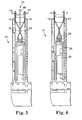
Fig. 5 is a sectional view through the terminal module ofFigs. 1 and 2 having a disconnector plug inserted from the front side; and -
Fig. 6 is a sectional view through the terminal module ofFigs. 1 and 2 having a disconnector plug inserted from the rear side. - A section through the
terminal module 10 is represented inFig. 1 . On thefront side 12 thereof,contact elements 14, 14' of the terminal module are uncovered to the outside in such a way thatcable cores 16, 16' can be connected thereto. This connection can occur by means of the insulation displacement contacting method of termination, during which a contact slot is formed at the end of therespective contact elements 14, 14', into which a cable core, consisting of a wire core and an insulating sheath, is inserted, with the sharp edges of the contact slot cutting through the sheath and contacting with the wire core. The terminal module shown inFig. 1 extends in a direction which is perpendicular to the drawing plane, so that overall there is a substantially block-shaped design. Further contact elements of the same type are provided on the terminal module in front of and behind thecontact elements 14, 14' which can be seen inFig. 1 , so that there a tworows 18 ofcontact elements 14.Wire routing components 20 are provided on the side faces of theterminal module 10, which have wire routing means, in particularwire routing channels 22. By way of these means, thecable cores 16, 16' connected to thefront side 12 are routed from the front side of themodule 10, on which the wire routing channels begin, either in a viewing direction when looking at the drawing, or in the opposite direction when viewing to the narrower side faces of the module. -
Module 10 is overall conveniently connected to anappropriate carrier 24, for example by latch mounting. There is asplitter group 26 inside the module, which, in the case illustrated, has a printedcircuit board 28 on whichelectronic components 30 are mounted. The electrical connection between theelectronic components 30, which are required to split up the transferred signals, and thecontact elements 14, 14', to which thecable cores 16, 16' are connected, results, on the one hand, via strip conductors which are imprinted on the printedcircuit board 28. Conversely, thesplitter group 26 hascable contact elements 32 which cannot be fully seen inFig.1 owing to the sectional drawing. Thecable contact elements 32 are, however, basically U-shaped with twolegs 34. In the case illustrated, one of the two legs has aprotrusion 36 at its front end so that the distance between bothlegs 34 is slightly reduced, at least in this area. The clamping of the rear or inner end of therespective contact elements 14, 14' occurs in this zone. Regardingcontact elements 14, 14', it must be said that they are conveniently stamped from sheet metal and extend at least a few millimeters perpendicularly to the drawing plane so that overall there is a strip-like design with appropriate inflexions as seen from the direction of thecable cores 16, 16'. Both upper surfaces of the strip-like design of thecontact elements 14, 14' are surrounded by the forkedcontact elements 32 and are contacted in an electrically conductive manner. Contactelements 14, 14' have a simple design since this design corresponds to a common design of separatable contact elements. In the illustrated embodiment, the contact elements have insulation displacement contact elements at their front end areas, which are basically defined by two contact legs lying one over the other, which are separated from each other by a slot. By inserting an insulated cable core into the slot, insulation is penetrated and the metal area inside the cable core is contacted. The contact elements can alternatively be configured as "wire-wrap pins" at these end areas. In these areas, the contact elements are clearly spaced apart from one another. Inside the modules, however, the contact elements have sections which come closer to each other than those areas of the contact elements which the cable cores are connected to. Generally speaking, the contact elements approach one another inside the module. They almost become contiguous thereby along twoareas 38, 38' in which the contact elements run parallel to one another. It must be noted that common separatable contact elements contact each other springingly in this area, whereby the contact can be interrupted by appropriate measures. - In the new terminal module, this connection at least during use is permanently separated so that the signal can be routed from one contact element via the attached forked
contact element 32 to the splitter group and from there again via the attached forked contact element 32' to the opposite contact element without a short circuit occurring at the same time inarea 38, 38'. - A
terminal module 10 is illustrated inFig. 1 , in which thecontact elements 14, 14' are, with regard to their geometry and design, conveniently configured in such a way that thecontact elements 14, 14' are separated from one another. It must be noted that thecontact elements 14, 14' can also be designed in such a way that they come into contact, for example, atareas 38, 38' in a condition in which the splitter group is removed. During use, a separating element is inserted between bothcontact elements 14, 14' in theseareas 38, 38' so that, as a result, they are electrically separated from one another. This separating element can be provided onsplitter group 26 so that in one step, the terminal module can be provided with the splitter group and the separation of thecontact elements 14, 14' and the connection of the same with thecontact elements 32, 32' of the splitter group occurs at the same time. Such a separating of the contact elements from inside the module furthermore offers the advantage over attaching a separating element on thefront side 12 in that the separating element cannot be pulled out unintentionally. - Regarding the ends of the
contact elements 14, 14' inside themodule 10, which are to be clamped by the forkedcontact elements 32, 32', it must be said that they are designed in such a way by means of the recognizable inflection that they can interact particularly reliably with a forkedcontact element 32, 32' to form an electro-conductive connection. For example, the inflection of contact element 14' recognized on the right and configured towards the left is responsible for the formation of a peak or a protrusion in this area which can be particularly well contacted by means of the right leg of the forked contact element 32'. - In the sectional representation of
Fig. 1 , a section of an earthing (grounding)component 40 can additionally be seen, the function of which becomes clearer from the sectional representation ofFig. 2 . During use, aninsulated cable 42 is attached to thecarrier 24. An external shielding 44 of the cable is fixed to thecarrier 24 by an appropriate measure, e.g. a bracket or clamp 46, and is thereby earthed. The so-called "drain cable" 48, in which a voltage is induced owing to the signal transmission, is routed to thefront side 12 of the terminal module and is connected to aspecific contact element 14. In order to divert the energy directed to thespecific contact element 14 to earth in this way, theterminal module 10 has the earthingcomponent 40 which can be configured as an earthing plate. On the end facing thefront side 12 of themodule 10, the earthingplate 40 hasappropriate fingers 50 which are connected in an electrically conductive manner to thosecontact elements 14, 14' which the "drain cables" are connected to. It must be noted that the earthingplate 40 can be provided on thesplitter groups 26 so that both the earthingplate 40, with thecontact elements 14, 14' required therefore, and thecontact elements 32, with therespective contact elements 14, 14' of theterminal module 10, can be connected in a single insertion step. - Furthermore, reference is made to German patent
DE-U 201 04 605 as well asWO-A-2002/076109 regarding the details of the construction of such a terminal block with integrated splitter groups. - In
Fig. 3 an embodiment of aterminal module 10 is shown, in whichcontact elements 14, 14' of a so-called connecting block are used. In the uncovered front area,contact elements 14, 14' again have insulation displacement contact areas to which cable cores can be connected. In the illustrated embodiment, both contact elements approach one another in their front areas owing to the respective configuration ofbulges 52, 52'. The strip-like areas of thecontact elements 14, 14', which extend perpendicularly to the drawing plane, are connected at asection 54, which extends largely parallel to the drawing plane. Again at a bending of 90°, twospring shackles 56 are configured at thissection 54, which approach one another but are, however, electrically separated from each other. This is true in the same way for the area in front of bothspring shackles 56, 56' where apartition 58 is provided. Thepartition 58 area and the area between thespring shackles 56, 56' is, however, accessible from thefront side 12, so that an appropriate plug or the like can be inserted here so that tests, measurements or connecting work can be carried out. The advantage that an established design of thecontact elements 14, 14' can be maintained and that asplitter group 26 can be integrated at the same time is also valid for this embodiment of the terminal module. The splitter group has forkedcontact elements 32 and 32', which are connected to the rear sections of thecontact elements 14, 14' in an electrically conductive manner, in a similar way to the embodiment inFigs. 1 and 2 in that they surround them. The signal is thus routed fromcontact element 14 of one side over the forkedcontact element 32 via the components of thesplitter groups 26, "split up" there and then the split signal is routed via the forked contact element 32' to the contact element 14' of the opposite side. - This mode of operation is also valid for the embodiment in
Fig. 4 . In this embodiment, theterminal module 10 has thesplitter group 26, however, no forked contact element, but rather contactelement 60 which is conveniently connected with spring shackles. For the separate connection withcontact elements 14, 14' of the terminal module,contact element 14 is routed from the one side to an area which is comparatively wide at the rear side of theterminal module 10 and is provided here with a section which interacts with the spring shackles of thecontact element 60. Contact element 14' of the opposite side approachescontact element 14 starting from its front end area, and has aspring shackle 62 in this area which interacts with aspecial contact element 64 to form adisconnectable separation point 66. In the normal condition, thespring shackle 62 thus abutscontact element 64 and creates and electro-conductive connection. Owing to the interaction the spring shackle of the front contact element 60' of the splitter group, contact element 14' is connected withcontact element 14 via the splitter group. Owing to the fact that the contact element 14' does, however, have theseparation point 66, a test, measurement or switch plug can be inserted here to carry out required actions if necessary. - In
Fig. 5 it is additionally shown, as in an embodiment of the terminal module which corresponds toFigs. 1 and 2 , that the separation of thecontact elements 14 and 14', so that they can be connected separately with the splitter group, can be configured. For this purpose, adisconnector plug 68 is inserted from thefront side 12. Bothcontact elements 14, 14' are hereby safely spaced apart from one another and electrically separated from one another, also inareas 38, 38' where they are comparatively close to one another. The transferred signal is hereby routed from thecable core 16 of one side via the splitter group, and from there is routed to the cable core 16' of the other side without causing a short circuit between thecable cores 16, 16' and thecontact elements 14, 14'. - This can also be achieved by the embodiment in
Fig. 6 . In this case, thedisconnector plug 68 is inserted from the rear side, i.e. the side with thesplitter group 26. This also leads to thecontact elements 14, 14' being spaced apart as required. This embodiment ofFig. 6 offers the advantage over the embodiment inFig. 5 that thedisconnector plug 68 is not easily accessible and thus, there is a lower probability of saiddisconnector plug 68 being unintentionally detached. The disconnector plug 68 can hereby be tightly connected to thesplitter group 26, in particular the printedcircuit board 28 thereof, so that whenever thesplitter group 26 is applied from the rear side of the module, it is guaranteed that thecontact elements 14, 14' will be separated.
Claims (10)
- A telecommunications terminal module (10) having:- an electrical or electronic component (26) having contact elements (32), and- two rows (18,18') of cable core contact elements (14,14') to which cable cores (16) can be connected from the outside of the terminal module (10) and which are capable of being connected with the contact elements (32) of the component (26) inside the terminal module (10), wherein the cable core contact elements (14,14') are designed in such a way that they approach each other inside the terminal module (10), at least in parts, are capable of being separately connected to the contact elements (32) of the component (26) when the component (26) is integrated in the terminal module (10),
characterized by- a separating element (68) provided at the component (26),- wherein with the component (26) integrated in the terminal module (10), the separating element (68) (i) is arranged between the cable core contact elements (14,14') and (ii) separates the cable core contact elements (14,14') from each other, and, with the component (26) removed from the terminal module (10), the cable core contact elements (14,14') (i) are disconnected from the contact elements (32) of the component (26) and (ii) abut one another. - The terminal module according to claim 1, wherein the component (26) is a splitter group.
- The terminal module according to claim 1, wherein the component (26) is adapted to allow testing and measurement of a line.
- The terminal module according to claim 3, wherein the component comprises a relay.
- The terminal module according to claim 1, wherein the component is adapted to protect against excess voltage, current, or both.
- A terminal module according to any one of claims 1 to 5, characterized in that at least one of the cable core contact elements (14, 14') has a separation point (66).
- A terminal module according to any one of claims 1 to 6, characterized in that the cable core contact elements (14) are designed to be largely strip-like.
- A terminal module according to one of claims 1 through 7, characterized in that the contact elements (32) of the component (26) are forked contact elements which are connected to the cable core contact elements (14) of the terminal module (10) when the component (26) is integrated in the terminal module (10).
- A terminal module according to one of claims 1 through 8, characterized in that said terminal module (10) has an earthing component (40) which is connected to individual cable core contact elements (14) of the terminal module (10).
- A terminal module according to claim 9, characterized in that the earthing component is an earthing plate (40).
Applications Claiming Priority (3)
| Application Number | Priority Date | Filing Date | Title |
|---|---|---|---|
| DE20203910U | 2002-03-11 | ||
| DE20203910U DE20203910U1 (en) | 2002-03-11 | 2002-03-11 | Connection module for telecommunications technology |
| PCT/US2003/006595 WO2003079643A2 (en) | 2002-03-11 | 2003-03-04 | Telecommunications terminal module |
Publications (3)
| Publication Number | Publication Date |
|---|---|
| EP1483808A2 EP1483808A2 (en) | 2004-12-08 |
| EP1483808A4 EP1483808A4 (en) | 2006-04-19 |
| EP1483808B1 true EP1483808B1 (en) | 2011-12-07 |
Family
ID=27618899
Family Applications (1)
| Application Number | Title | Priority Date | Filing Date |
|---|---|---|---|
| EP03713884A Expired - Lifetime EP1483808B1 (en) | 2002-03-11 | 2003-03-04 | Telecommunications terminal module |
Country Status (13)
| Country | Link |
|---|---|
| US (1) | US7140926B2 (en) |
| EP (1) | EP1483808B1 (en) |
| JP (1) | JP2005527140A (en) |
| CN (1) | CN1643748A (en) |
| AT (1) | ATE536650T1 (en) |
| AU (1) | AU2003217911A1 (en) |
| BR (1) | BR0307744A (en) |
| CA (1) | CA2475951A1 (en) |
| DE (1) | DE20203910U1 (en) |
| ES (1) | ES2378304T3 (en) |
| MX (1) | MXPA04008688A (en) |
| WO (1) | WO2003079643A2 (en) |
| ZA (1) | ZA200408118B (en) |
Families Citing this family (12)
| Publication number | Priority date | Publication date | Assignee | Title |
|---|---|---|---|---|
| DE10331564A1 (en) * | 2003-07-11 | 2005-02-10 | Siemens Ag | Plug in splitter for a band splitter for use in broadband networks such as access networks, whereby only broad or narrow band information is returned via a splitter output to the band splitter |
| FR2863409B1 (en) * | 2003-12-09 | 2009-01-23 | Nexans | CABLE INTERCONNECTION MODULE AND REGULATOR |
| ES2372177T3 (en) * | 2004-11-24 | 2012-01-16 | 3M Innovative Properties Company | TELECOMMUNICATIONS MODULE, COMBINATION OF A TELECOMMUNICATIONS MODULE AND AT LEAST A DIVIDING CIRCUIT, AND SET OF AT LEAST TWO TELECOMMUNICATIONS MODULES. |
| DE602005018157D1 (en) * | 2005-02-03 | 2010-01-21 | 3M Innovative Properties Co | Function module and arrangement comprising at least one telecommunication module and at least one functional module |
| EP1699112A1 (en) * | 2005-03-04 | 2006-09-06 | 3M Innovative Properties Company | A telecommunications module, an assembly of a telecommunications module and at least one outside module and a method of using a telecommunications module |
| ATE450909T1 (en) * | 2005-09-30 | 2009-12-15 | 3M Innovative Properties Co | PLUG FOR TELECOMMUNICATIONS, ARRANGEMENT COMPRISING A TELECOMMUNICATIONS MODULE AND A PLUG, AND PRODUCTION METHOD FOR A PLUG |
| EP1804524A1 (en) * | 2005-12-29 | 2007-07-04 | 3M Innovative Properties Company | A telecommunications assembly including at least one telecommunications module, a test bus and a kit of parts |
| US7657023B2 (en) * | 2007-06-08 | 2010-02-02 | At&T Intellectual Property I, L.P. | Splitter wall plates for digital subscriber line (DSL) communication systems and methods to use the same |
| DE102012111718A1 (en) * | 2012-12-03 | 2014-06-05 | Reichle & De-Massari Ag | A method for combining electrical and optical signals and socket connection apparatus for use in the method |
| EP2804392A1 (en) * | 2013-05-17 | 2014-11-19 | 3M Innovative Properties Company | Termination module |
| CN109451369B (en) * | 2018-12-28 | 2021-05-11 | 安徽长泰信息安全服务有限公司 | A kind of switch for communication engineering |
| CN112234554B (en) * | 2020-10-09 | 2022-04-05 | 嘉兴新博信息科技有限公司 | Line beam-returning protection device for 5G base station |
Family Cites Families (22)
| Publication number | Priority date | Publication date | Assignee | Title |
|---|---|---|---|---|
| US2863970A (en) * | 1957-11-04 | 1958-12-09 | Eugene A Miller | Circuit breaker |
| US3751618A (en) | 1972-02-23 | 1973-08-07 | Hi Tek Corp | Push-switch with spring biased plunger |
| US4286121A (en) | 1979-10-25 | 1981-08-25 | Northern Telecom Limited | Telephone line cutover apparatus and switch |
| DE3509523C3 (en) * | 1985-03-16 | 1996-07-04 | Quante Ag | Cable termination unit |
| DE3614063C3 (en) * | 1986-04-23 | 1994-02-24 | Krone Ag | Distribution device, in particular for the main distributor of telephone systems |
| DE3644349C1 (en) * | 1986-12-19 | 1988-02-25 | Krone Ag | Terminal block for telecommunications |
| DE4042240C2 (en) * | 1990-12-31 | 1994-12-15 | Quante Ag | Connection module for a distribution device, in particular for the main distributor of telecommunication devices |
| US5451170A (en) * | 1993-09-28 | 1995-09-19 | Reliance Comm/Tec Corporation | Terminal block with protection |
| CA2147410A1 (en) * | 1995-04-20 | 1996-10-21 | Robert L. Romerein | Circuitry for use with coaxial cable distribution networks |
| EP0766482A3 (en) * | 1995-09-29 | 2000-02-02 | KRONE Aktiengesellschaft | Distribution device for the telecommuncation and data technology |
| AR010100A1 (en) * | 1997-01-13 | 2000-05-17 | Ccs Technology Inc | ARRANGEMENT TO REGULATE THE POSITION OF SWITCHING OF CONTACTS OF A MODULAR CONTACTING ELEMENT |
| US6438226B1 (en) * | 1997-10-06 | 2002-08-20 | Ccs Holdings, Inc. | XDSL splitter assembly for main distribution frame |
| US6005497A (en) * | 1997-10-20 | 1999-12-21 | Ericsson Inc. | Power control latch |
| US6385315B1 (en) * | 1998-06-05 | 2002-05-07 | Mphase Corporation | Video voice separation system |
| US6089923A (en) | 1999-08-20 | 2000-07-18 | Adc Telecommunications, Inc. | Jack including crosstalk compensation for printed circuit board |
| DE19940101A1 (en) | 1999-08-24 | 2001-03-22 | Braun Gmbh | Multi-pin connector for low voltage devices |
| US6430288B1 (en) * | 1999-10-14 | 2002-08-06 | Corning Cable Systems Llc | Phone line splitter assembly |
| DE10029649C9 (en) * | 2000-06-15 | 2008-02-07 | Adc Gmbh | Distribution terminal module for telecommunications and data technology |
| DE10029870A1 (en) * | 2000-06-16 | 2002-01-03 | Rxs Kabelgarnituren Gmbh & Co | Distribution device of a data signal processing system and data signal processing system |
| AU2002239762A1 (en) | 2000-10-23 | 2002-06-03 | Adc Telecommunications Inc. | Birefringent interleaver for wdm fiber optic communications |
| DE20104605U1 (en) | 2001-03-16 | 2001-05-31 | 3M Innovative Properties Co., St. Paul, Minn. | Terminal block and distribution device |
| DE20200746U1 (en) | 2002-01-18 | 2002-04-04 | 3M Innovative Properties Co., St. Paul, Minn. | Terminal block and distributor device with one terminal block |
-
2002
- 2002-03-11 DE DE20203910U patent/DE20203910U1/en not_active Expired - Lifetime
-
2003
- 2003-03-04 ES ES03713884T patent/ES2378304T3/en not_active Expired - Lifetime
- 2003-03-04 US US10/504,935 patent/US7140926B2/en not_active Expired - Fee Related
- 2003-03-04 BR BR0307744-6A patent/BR0307744A/en not_active Application Discontinuation
- 2003-03-04 EP EP03713884A patent/EP1483808B1/en not_active Expired - Lifetime
- 2003-03-04 MX MXPA04008688A patent/MXPA04008688A/en unknown
- 2003-03-04 CA CA002475951A patent/CA2475951A1/en not_active Abandoned
- 2003-03-04 AU AU2003217911A patent/AU2003217911A1/en not_active Abandoned
- 2003-03-04 WO PCT/US2003/006595 patent/WO2003079643A2/en not_active Ceased
- 2003-03-04 CN CNA038057956A patent/CN1643748A/en active Pending
- 2003-03-04 JP JP2003577505A patent/JP2005527140A/en active Pending
- 2003-03-04 AT AT03713884T patent/ATE536650T1/en active
-
2004
- 2004-10-07 ZA ZA200408118A patent/ZA200408118B/en unknown
Also Published As
| Publication number | Publication date |
|---|---|
| CA2475951A1 (en) | 2003-09-25 |
| ES2378304T3 (en) | 2012-04-11 |
| JP2005527140A (en) | 2005-09-08 |
| CN1643748A (en) | 2005-07-20 |
| ZA200408118B (en) | 2005-10-13 |
| US7140926B2 (en) | 2006-11-28 |
| EP1483808A2 (en) | 2004-12-08 |
| EP1483808A4 (en) | 2006-04-19 |
| DE20203910U1 (en) | 2003-07-17 |
| WO2003079643A3 (en) | 2003-12-31 |
| US20050191908A1 (en) | 2005-09-01 |
| WO2003079643A2 (en) | 2003-09-25 |
| ATE536650T1 (en) | 2011-12-15 |
| MXPA04008688A (en) | 2004-12-06 |
| BR0307744A (en) | 2005-04-26 |
| AU2003217911A1 (en) | 2003-09-29 |
Similar Documents
| Publication | Publication Date | Title |
|---|---|---|
| US4729064A (en) | Modular interconnect block with protector structure | |
| JPH0564915B2 (en) | ||
| US7140926B2 (en) | Telecommunications terminal module | |
| US5928008A (en) | Earthing module | |
| US7059864B2 (en) | Distribution device of a telecommunications system | |
| JPH09190849A (en) | Modular multiple-connection terminal block for connecting cables in the main distribution of communication and data conductors | |
| RU2365004C2 (en) | Plug-in overvoltage protection device | |
| RU2569326C2 (en) | Distributor connection module | |
| EP1455543B1 (en) | Assembly of a telecommunications module and at least one protection plug | |
| RU2353071C1 (en) | Telecommunication module, and assembly containing telecommunication module | |
| EP1578144B1 (en) | Modular arrangement in the field of telecommunications | |
| EP1770832B1 (en) | Telecommunications plug, an assembly including a telecommunications module and a plug, and a method of manufacturing a plug | |
| EP1699117A1 (en) | A telecommunications module, an assembly of a telecommunications module and at least one outside module, a method for manufacturing a telecommunications module, and a use of a telecommunications module | |
| AU691182B2 (en) | Loading coil device | |
| US20090053934A1 (en) | Termination block with functional module | |
| JP2006521764A (en) | Communication module and combination comprising at least one communication module | |
| KR20060015300A (en) | ADL terminal block | |
| EP1804524A1 (en) | A telecommunications assembly including at least one telecommunications module, a test bus and a kit of parts | |
| MX2008008314A (en) | A telecommunications assembly including at least one telecommunications module, a test bus and a kit of parts | |
| WO2006096341A1 (en) | Telecommunications modules, assemblies thereof and methods of using same |
Legal Events
| Date | Code | Title | Description |
|---|---|---|---|
| PUAI | Public reference made under article 153(3) epc to a published international application that has entered the european phase |
Free format text: ORIGINAL CODE: 0009012 |
|
| 17P | Request for examination filed |
Effective date: 20040820 |
|
| AK | Designated contracting states |
Kind code of ref document: A2 Designated state(s): AT BE BG CH CY CZ DE DK EE ES FI FR GB GR HU IE IT LI LU MC NL PT RO SE SI SK TR |
|
| AX | Request for extension of the european patent |
Extension state: AL LT LV MK |
|
| A4 | Supplementary search report drawn up and despatched |
Effective date: 20060303 |
|
| 17Q | First examination report despatched |
Effective date: 20061123 |
|
| GRAP | Despatch of communication of intention to grant a patent |
Free format text: ORIGINAL CODE: EPIDOSNIGR1 |
|
| GRAS | Grant fee paid |
Free format text: ORIGINAL CODE: EPIDOSNIGR3 |
|
| GRAA | (expected) grant |
Free format text: ORIGINAL CODE: 0009210 |
|
| AK | Designated contracting states |
Kind code of ref document: B1 Designated state(s): AT BE BG CH CY CZ DE DK EE ES FI FR GB GR HU IE IT LI LU MC NL PT RO SE SI SK TR |
|
| REG | Reference to a national code |
Ref country code: GB Ref legal event code: FG4D |
|
| REG | Reference to a national code |
Ref country code: CH Ref legal event code: EP |
|
| REG | Reference to a national code |
Ref country code: IE Ref legal event code: FG4D |
|
| REG | Reference to a national code |
Ref country code: DE Ref legal event code: R096 Ref document number: 60339328 Country of ref document: DE Effective date: 20120216 |
|
| REG | Reference to a national code |
Ref country code: NL Ref legal event code: VDEP Effective date: 20111207 |
|
| REG | Reference to a national code |
Ref country code: ES Ref legal event code: FG2A Ref document number: 2378304 Country of ref document: ES Kind code of ref document: T3 Effective date: 20120411 |
|
| PGFP | Annual fee paid to national office [announced via postgrant information from national office to epo] |
Ref country code: FR Payment date: 20120319 Year of fee payment: 10 |
|
| PG25 | Lapsed in a contracting state [announced via postgrant information from national office to epo] |
Ref country code: SI Free format text: LAPSE BECAUSE OF FAILURE TO SUBMIT A TRANSLATION OF THE DESCRIPTION OR TO PAY THE FEE WITHIN THE PRESCRIBED TIME-LIMIT Effective date: 20111207 Ref country code: SE Free format text: LAPSE BECAUSE OF FAILURE TO SUBMIT A TRANSLATION OF THE DESCRIPTION OR TO PAY THE FEE WITHIN THE PRESCRIBED TIME-LIMIT Effective date: 20111207 Ref country code: GR Free format text: LAPSE BECAUSE OF FAILURE TO SUBMIT A TRANSLATION OF THE DESCRIPTION OR TO PAY THE FEE WITHIN THE PRESCRIBED TIME-LIMIT Effective date: 20120308 Ref country code: NL Free format text: LAPSE BECAUSE OF FAILURE TO SUBMIT A TRANSLATION OF THE DESCRIPTION OR TO PAY THE FEE WITHIN THE PRESCRIBED TIME-LIMIT Effective date: 20111207 |
|
| PGFP | Annual fee paid to national office [announced via postgrant information from national office to epo] |
Ref country code: TR Payment date: 20120209 Year of fee payment: 10 |
|
| PG25 | Lapsed in a contracting state [announced via postgrant information from national office to epo] |
Ref country code: BE Free format text: LAPSE BECAUSE OF FAILURE TO SUBMIT A TRANSLATION OF THE DESCRIPTION OR TO PAY THE FEE WITHIN THE PRESCRIBED TIME-LIMIT Effective date: 20111207 Ref country code: CY Free format text: LAPSE BECAUSE OF FAILURE TO SUBMIT A TRANSLATION OF THE DESCRIPTION OR TO PAY THE FEE WITHIN THE PRESCRIBED TIME-LIMIT Effective date: 20111207 |
|
| PGFP | Annual fee paid to national office [announced via postgrant information from national office to epo] |
Ref country code: GB Payment date: 20120301 Year of fee payment: 10 |
|
| PG25 | Lapsed in a contracting state [announced via postgrant information from national office to epo] |
Ref country code: BG Free format text: LAPSE BECAUSE OF FAILURE TO SUBMIT A TRANSLATION OF THE DESCRIPTION OR TO PAY THE FEE WITHIN THE PRESCRIBED TIME-LIMIT Effective date: 20120307 Ref country code: EE Free format text: LAPSE BECAUSE OF FAILURE TO SUBMIT A TRANSLATION OF THE DESCRIPTION OR TO PAY THE FEE WITHIN THE PRESCRIBED TIME-LIMIT Effective date: 20111207 Ref country code: SK Free format text: LAPSE BECAUSE OF FAILURE TO SUBMIT A TRANSLATION OF THE DESCRIPTION OR TO PAY THE FEE WITHIN THE PRESCRIBED TIME-LIMIT Effective date: 20111207 Ref country code: CZ Free format text: LAPSE BECAUSE OF FAILURE TO SUBMIT A TRANSLATION OF THE DESCRIPTION OR TO PAY THE FEE WITHIN THE PRESCRIBED TIME-LIMIT Effective date: 20111207 |
|
| PG25 | Lapsed in a contracting state [announced via postgrant information from national office to epo] |
Ref country code: PT Free format text: LAPSE BECAUSE OF FAILURE TO SUBMIT A TRANSLATION OF THE DESCRIPTION OR TO PAY THE FEE WITHIN THE PRESCRIBED TIME-LIMIT Effective date: 20120409 Ref country code: RO Free format text: LAPSE BECAUSE OF FAILURE TO SUBMIT A TRANSLATION OF THE DESCRIPTION OR TO PAY THE FEE WITHIN THE PRESCRIBED TIME-LIMIT Effective date: 20111207 |
|
| REG | Reference to a national code |
Ref country code: AT Ref legal event code: MK05 Ref document number: 536650 Country of ref document: AT Kind code of ref document: T Effective date: 20111207 |
|
| PLBE | No opposition filed within time limit |
Free format text: ORIGINAL CODE: 0009261 |
|
| STAA | Information on the status of an ep patent application or granted ep patent |
Free format text: STATUS: NO OPPOSITION FILED WITHIN TIME LIMIT |
|
| PG25 | Lapsed in a contracting state [announced via postgrant information from national office to epo] |
Ref country code: DK Free format text: LAPSE BECAUSE OF FAILURE TO SUBMIT A TRANSLATION OF THE DESCRIPTION OR TO PAY THE FEE WITHIN THE PRESCRIBED TIME-LIMIT Effective date: 20111207 Ref country code: MC Free format text: LAPSE BECAUSE OF NON-PAYMENT OF DUE FEES Effective date: 20120331 |
|
| REG | Reference to a national code |
Ref country code: CH Ref legal event code: PL |
|
| 26N | No opposition filed |
Effective date: 20120910 |
|
| PG25 | Lapsed in a contracting state [announced via postgrant information from national office to epo] |
Ref country code: IT Free format text: LAPSE BECAUSE OF FAILURE TO SUBMIT A TRANSLATION OF THE DESCRIPTION OR TO PAY THE FEE WITHIN THE PRESCRIBED TIME-LIMIT Effective date: 20111207 |
|
| PGFP | Annual fee paid to national office [announced via postgrant information from national office to epo] |
Ref country code: ES Payment date: 20120419 Year of fee payment: 10 |
|
| REG | Reference to a national code |
Ref country code: IE Ref legal event code: MM4A |
|
| REG | Reference to a national code |
Ref country code: DE Ref legal event code: R097 Ref document number: 60339328 Country of ref document: DE Effective date: 20120910 |
|
| REG | Reference to a national code |
Ref country code: DE Ref legal event code: R119 Ref document number: 60339328 Country of ref document: DE Effective date: 20121002 |
|
| PG25 | Lapsed in a contracting state [announced via postgrant information from national office to epo] |
Ref country code: CH Free format text: LAPSE BECAUSE OF NON-PAYMENT OF DUE FEES Effective date: 20120331 Ref country code: IE Free format text: LAPSE BECAUSE OF NON-PAYMENT OF DUE FEES Effective date: 20120304 Ref country code: AT Free format text: LAPSE BECAUSE OF FAILURE TO SUBMIT A TRANSLATION OF THE DESCRIPTION OR TO PAY THE FEE WITHIN THE PRESCRIBED TIME-LIMIT Effective date: 20111207 Ref country code: LI Free format text: LAPSE BECAUSE OF NON-PAYMENT OF DUE FEES Effective date: 20120331 |
|
| PG25 | Lapsed in a contracting state [announced via postgrant information from national office to epo] |
Ref country code: FI Free format text: LAPSE BECAUSE OF FAILURE TO SUBMIT A TRANSLATION OF THE DESCRIPTION OR TO PAY THE FEE WITHIN THE PRESCRIBED TIME-LIMIT Effective date: 20111207 |
|
| GBPC | Gb: european patent ceased through non-payment of renewal fee |
Effective date: 20130304 |
|
| REG | Reference to a national code |
Ref country code: FR Ref legal event code: ST Effective date: 20131129 |
|
| PG25 | Lapsed in a contracting state [announced via postgrant information from national office to epo] |
Ref country code: FR Free format text: LAPSE BECAUSE OF NON-PAYMENT OF DUE FEES Effective date: 20130402 Ref country code: GB Free format text: LAPSE BECAUSE OF NON-PAYMENT OF DUE FEES Effective date: 20130304 |
|
| PG25 | Lapsed in a contracting state [announced via postgrant information from national office to epo] |
Ref country code: LU Free format text: LAPSE BECAUSE OF NON-PAYMENT OF DUE FEES Effective date: 20120304 |
|
| REG | Reference to a national code |
Ref country code: ES Ref legal event code: FD2A Effective date: 20140715 |
|
| PG25 | Lapsed in a contracting state [announced via postgrant information from national office to epo] |
Ref country code: HU Free format text: LAPSE BECAUSE OF FAILURE TO SUBMIT A TRANSLATION OF THE DESCRIPTION OR TO PAY THE FEE WITHIN THE PRESCRIBED TIME-LIMIT Effective date: 20030304 |
|
| PG25 | Lapsed in a contracting state [announced via postgrant information from national office to epo] |
Ref country code: DE Free format text: LAPSE BECAUSE OF FAILURE TO SUBMIT A TRANSLATION OF THE DESCRIPTION OR TO PAY THE FEE WITHIN THE PRESCRIBED TIME-LIMIT Effective date: 20121002 |
|
| PG25 | Lapsed in a contracting state [announced via postgrant information from national office to epo] |
Ref country code: ES Free format text: LAPSE BECAUSE OF NON-PAYMENT OF DUE FEES Effective date: 20130305 |
|
| PG25 | Lapsed in a contracting state [announced via postgrant information from national office to epo] |
Ref country code: TR Free format text: LAPSE BECAUSE OF NON-PAYMENT OF DUE FEES Effective date: 20130304 |