EP1482722A2 - Systems and methods for designing digital anamorphic line screens - Google Patents
Systems and methods for designing digital anamorphic line screens Download PDFInfo
- Publication number
- EP1482722A2 EP1482722A2 EP04012342A EP04012342A EP1482722A2 EP 1482722 A2 EP1482722 A2 EP 1482722A2 EP 04012342 A EP04012342 A EP 04012342A EP 04012342 A EP04012342 A EP 04012342A EP 1482722 A2 EP1482722 A2 EP 1482722A2
- Authority
- EP
- European Patent Office
- Prior art keywords
- addressability
- vector
- direction component
- low
- cycles
- Prior art date
- Legal status (The legal status is an assumption and is not a legal conclusion. Google has not performed a legal analysis and makes no representation as to the accuracy of the status listed.)
- Granted
Links
Images




Classifications
-
- H—ELECTRICITY
- H04—ELECTRIC COMMUNICATION TECHNIQUE
- H04N—PICTORIAL COMMUNICATION, e.g. TELEVISION
- H04N1/00—Scanning, transmission or reproduction of documents or the like, e.g. facsimile transmission; Details thereof
- H04N1/40—Picture signal circuits
- H04N1/405—Halftoning, i.e. converting the picture signal of a continuous-tone original into a corresponding signal showing only two levels
- H04N1/4055—Halftoning, i.e. converting the picture signal of a continuous-tone original into a corresponding signal showing only two levels producing a clustered dots or a size modulated halftone pattern
- H04N1/4058—Halftoning, i.e. converting the picture signal of a continuous-tone original into a corresponding signal showing only two levels producing a clustered dots or a size modulated halftone pattern with details for producing a halftone screen at an oblique angle
Definitions
- This invention is directed to determining the design parameters for lines screens.
- marking technologies such as offset printing, laser printing, and inkjet printing
- Holladay discloses a method for creating a halftone cell that forms a screen pattern at some desired angle to the process/scanning directions.
- the screen pattern is formed by repeatedly tiling the halftone cell over the plane of the image receiving substrate.
- the resulting screen pattern includes rows of dots, each dot made from a number of pixels.
- Holladay's technique allows for the halftone screen to be created at various desired angles.
- digital cluster dot screens use isometric dots, i.e., dots having the same length side vectors a and b .
- digital cluster dot screens are normally square, such that the vectors a and b are at right angles to each other. Because of the geometric constraints, the angles and frequencies that can be achieved using Holladay's technique are significantly limited.
- This invention provides systems and methods for designing digital line screens that eliminate the geometric requirements of digital cluster dot screens.
- This invention separately provides systems and methods for designing digital line screens that use the high-addressability spacing to determine the frequency and angle of the line screens.
- This invention separately provides systems and methods for designing anamorphic digital line screens that use different resolution in the x and y directions.
- This invention separately provides systems and methods for designing digital line screens that use vectors having lengths along a high-addressability direction of a high-addressability grid that are not multiples of the addressability factor.
- a digital line screen cell is define such that the vectors defining the digital line screen cell are not necessarily isometric and are not necessarily at right angles to each other.
- the systems and methods according to this invention allow the components of the vectors along the high-addressability direction to be noninteger multiples of the components of the vectors along the other direction of the grid.
- Fig. 1 shows an isometric, square digital line screen aligned to the low-addressability cells of a high-addressability grid
- Fig. 2 shows the Holladay brick usable to implement the halftone digital line screen shown in Fig. 1;
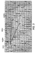
- Fig. 3 shows an anamorphic digital line screen according to this invention aligned to the high-addressability grid
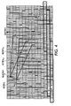
- Fig. 4 shows one exemplary embodiment of a Holladay brick usable to implement the digital anamorphic line screen shown in Fig. 3;
- Fig. 5 is a flowchart outlining a first exemplary embodiment of a method for designing a digital anamorphic line screen according to this invention.
- Figs. 6 and 7 illustrate exemplary digital anamorphic line screens designed according to this invention.
- the systems and methods according to this invention provide techniques for designing digital line screens that allow more accurate screen angles to be selected and allow much more flexibility in the line frequency that is produced.
- this increased accuracy in the screen angles is obtained by using the anamorphic resolution provided by high-addressability image forming devices.
- the increase in flexibility is achieved by allowing the Holladay brick width and the Holladay shift parameters to take any value enabled by the high-addressability anamorphic resolution, rather than restricting these values to be multiples of the high-addressability factor.
- High-addressability image forming systems have a first resolution, usually in the slow scan direction, that is lower than a high-addressability resolution, which is usually in the fast scan direction.
- the ratio between the special resolution along the high-addressability direction relative to the standard resolution direction is the high-addressability factor a.
- U.S. Patent 5,274,472 to Williams which is incorportated herein by reference in its entirety, discloses methods for converting gray level image data from image input terminals into binary data for high addressability image output terminals.
- U.S. Patent 5,485,289 to Curry which is incorportated herein by reference in its entirety, discloses printing systems for rendering bitmapped image data on a photosensitive recording medium.
- Curry's system includes a data source for supplying grayscale input image data and a scanning device for rendering grayscale output image data onto the recording medium.
- a vector is defined on the basic resolution grid at the desired screen angle to the basic resolution grid.
- the length of the vector is defined as the inverse of the desired frequency of the halftone dot or line screen. Since the vector is defined on the basic grid, this vector is represented as a pair of components along the x, or fast scan direction and the y, or slow scan direction, where the x and y components are both integers relative to the basic resolution grid. In Fig. 1, this first vector is labeled a . After the first vector a , having components (x, y), is defined, the square symmetry assumption requires that the second vector, shown in Fig.
- the square symmetry assumption means that the vector components x' and y' are equal to y and -x, respectively. That is, the x component of the second vector b is the same value as the y component of the first vector a , while the y' component of the second vector b is the inverse of the x component of the first vector a . As shown in Fig. 1, these two vectors a and b together define a basic halftone cell C, which is repeated or tiled over the plane of a high-addressability grid 100.
- each level of the halftone line screen is formed by marking an additional one of a number of high-addressability cells 110 adjacent to either side of the first four cells that establish a line within the basic cell C.
- the basic cell C is shown as a line screen having a halftone value of 8.
- High-addressability raster or scanning is defined as a system where the pixel resolution in one direction is an integer multiple of the pixel resolution in the other direction. This can be accomplished by increasing the clock speed along a scan line by an integer multiple in an otherwise normal system.
- Figs. 1-4 illustrate an 8:1 high-addressability system having a high-addressability factor in the x direction of 8. Because of this, each logical pixel 110 in the high-addressability grid 100 appears as a tall skinny rectangle.
- the high-addressability factor a there is a fixed integer relationship, i.e., the high-addressability factor a, between the steps in the x direction and the steps in the y direction. Because, due to the isometric assumption illustrated in the basic halftone line screen cell shown in Figs. 1 and 2, it follows that the value of x for a square dot on a high-addressability grid can only assume multiples of the addressability factor a. For example, for the exemplary embodiment shown in Figs. 1 and 2, x can assume only values of 0, 8, 16, 24....in units of the high-addressability spacing. In the specific exemplary embodiment shown in Figs.
- the Holladay brick will have a width that is a multiple of the addressability factor a.
- the horizontal steps or shift between bricks will also be a multiple of the addressability factor a.
- the implementation of the Holladay brick shown in Fig. 2 is a Holladay brick that is two scan lines high by 80 high-addressability units wide, where there is a shift of 48 high-addressability units between vertically-adjacent Holladay bricks.
- halftone line screens As opposed to the halftone dot screens discussed above, the situation is different.
- the only relevant parameter in one direction is the screen angle, while the only relevant parameter in the orthogonal direction is the line frequency of the halftone line screen. That is, there is no requirement for the effective halftone line screen itself to be square, or even isometric. Accordingly, for halftone line screens, such halftone line screens are able to use the full addressability of the high-addressability grid to gain more precision in the angle in the primary screen vector. That is, halftone line screens can be anamorphic. Moreover, for such halftone line screens, it is not necessary for the second vector to be perpendicular or orthogonal to the primary screen vector. Accordingly, the full addressability can be used to increase the precision of the effective halftone line screen frequency.
- a first vector V 1 is defined such that the first vector V 1 is parallel to the desired halftone line screen. That is, the first vector V 1 is defined to obtain a desired angle ⁇ for the halftone line screen relative to a reference direction.
- This reference direction is often the high-addressability axis of the grid, which is usually defined as the x axis.
- the low-resolution, scan line direction which is orthogonal to the high-addressability direction, is defined as the y axis.
- the halftone line screen angle ⁇ is tan -1 (y/x).
- the desired frequency F of the halftone line screen can be, and usually is, defined independently of the angle ⁇ of the halftone line screen.
- the desired frequency F of the halftone line screen is defined as the number of halftone screen lines that occur in the halftone line screen per inch.
- the base resolution R of the underlying raster grid on which the halftone line screen is formed is defined as the number of raster scan lines per inch. That is, the base resolution R defines the y-axis resolution.
- the base-resolution R along the x axis i.e., the x-axis resolution
- the low-resolution dimension x along the fast-scan direction is equal to the raster scan line resolution along the y or slow-scan direction.
- the high-addressability resolution or size of the high-addressability units u is thus equal to the low-resolution x divided by the high-addressability factor a.
- the perpendicular distance between the halftone line structures of the halftone line screen defined by Eqs. (4) and (6) is the inverse of the desired frequency of the lines of the halftone line screen.
- Eqs. (4) and (5) pass through the origin, and Eqs. (6) is parallel to Eq. (4) but is aligned with the next phase of the halftone line screen
- the perpendicular distance d between the halftone line structures of the halftone line screen is equal to the distance d from the origin to the intercept I.
- a halftone cell may contain n cycles or phases of the halftone line screen.
- Fig. 3 shows two cases for the second vector V 2 .
- the first case which is associated with the upper vector V 2 in Fig.
- this second case for the vector V 2 is much closer to being perpendicular to the lines defined by Eqs. (4) and (6).
- this second case for the second vector V 2 is a redundant case, since the value of the y-component y 1 (and thus the v-component v 1 ) for the first vector V 1 is 2, and because (-5) modulo 2 is equal to (-1) modulo 2.
- both vectors will produce the identical Holladay blocks, as discussed below with respect to Fig. 4.
- d n is a perpendicular distance for a given particular number of cycles n.
- y 2i is the i th value for the y-component y 2 of the second vector V 2 ;
- x 2 (n) i is the value for the i th x-component x 2 of the second vector V 2 for the n th perpendicular distance d n and the i th value for the y-component y 2 of the second vector V 2 .
- x 2 (n) i ((nR/F) ⁇ (m 2 + 1) .5 + y 2i )/m.
- n x i values u 2 (n) i represent realizable x-components u 2 for the second vector V 2 based on the high-addressability resolution.
- These realizable x-component values u 2 can then be used to determine the n x i actual, realizable frequency values f for the halftone line screen.
- Table 1 shows the various values for the x-component x 2 and the high-addressability x-component u 2 , the actual realizable frequency f and the block width and shift values for the resulting Holladay blocks for a halftone screen having a base resolution R of 600 scan lines per inch, and a high-addressability factor of 8, where the desired frequency F is 170 halftone lines per inch, the desired angle ⁇ of the halftone line screen is 66.37° and the first vector V 1 has x-component and y-component values x 1 and y 1 of 0.875 and 2, which translates to high-addressability x-component and y-component values u 1 and v 1 of 7 and 2.
- the y-component y 1 of the first vector V 1 is 2
- the "best" values are those that require the least amount of rounding of the raw high-addressability x-component u 2 to get integer-valued high-addressability x-components u 2 .
- the high-addressability x-component u 2 (3) 1 gives a value for the high-addressability x-component u 2 (3) 1 of 88.958, requiring rounding up by 0.42
- rounding u 2 of 88.958 requires less rounding than the value of u 2 of 243.054
- the actual realizable frequency f 1 (3) is 3*600/10.5931, or 169.922°.
- the actual realizable frequency f 1 (8) is 8*600/28.2291, or 170.037°.
- the rounding error for u 2 (8) is approximately equal to the rounding error for u 2 (3) 1 , but because that rounding error is spread over 8/3 as much space, the ultimate error in the actual frequency f relative to the desired frequency F for u 2 (8) 1 is less than half that for u 2 (3) 1 .
- Fig. 4 shows two redundant solutions for the second vector V and the corresponding halftone cells obtained for these two possible second vectors V 2 relative to the first vector V 1 .
- Fig. 4 also shows the Holladay block and shift for the unique halftone cell corresponding to both vectors. That is, the Holladay block for this vector V 2 is 185 high-addressability units by 1 scan line with a shift of 96 high-addressability units.
- the disclosed algorithm includes the parameters "D” and "S”, which represent the shift parameter for either Left or Right shifts, respectively.
- D and S represent the shift parameter for either Left or Right shifts, respectively.
- these D and S shift parameters are sometimes reversed to represent the Right and Left shifts, respectively.
- this resulting Holladay brick is extremely unwieldy. This is due to its extreme length and thinness.
- Fig. 5 is a flowchart outlining one exemplary embodiment of a method for determining a Holladay brick for an anamorphic halftone line screen formed using a high-addressability grid.
- step S100 operation continues to step S110, where a desired screen angle ⁇ and a desired screen frequency F of the halftone line screen are input.
- step S120 a first vector V 1 is located using the high-addressability grid to produce the desired angle ⁇ .
- step S130 the slope m of the located first vector V 1 relative to the high-addressability raster grid is determined. Operation then continues to step S140.
- step S140 the set of possible y-components y 2i of the second vector V 2 is determined.
- the number of possible y-components y 2i is determined by the value of the y-component y 1 of the first vector V 1 .
- step S150 a maximum number N of halftone cycles n that can, or are allowed to, occur in the Holladay brick to be formed is determined or selected.
- step S160 for each different number of halftone cycles n that can or that are allowed to occur in the Holladay brick, and for each different y-component y 2i of the second vector V 2 , a value for the high-addressability component ax 2i (n) 1 or u 2i (n) is determined. Operation then continues to step S170.
- step S170 at least one of the possible second vectors V 2i (n) that has a high-addressability component u 2i (n) that is close to an integer value of high-addressability units is determined or located.
- step S180 each of the high-addressability components u 2i (n) determined or located in step S170 is rounded to the nearest integer value.
- step S190 the Holladay brick with W and offset D for the rounded high-addressability component u 2i (n) is determined for each of the determined or located second vectors V 2i (n). Operation then continues to step S200.
- step S200 if more than one second vector V 2i (n) was determined or located in step S170, one of the corresponding Holladay bricks for the different determined or located second vectors V 2i (n) is selected as the desired Holladay brick for the desired angle ⁇ and the desired screen frequency F for the halftone line screen.
- the Holladay brick corresponding to that determined or located second vector V 2 is selected automatically. Operation then continues to step S210, where operation of the method ends.
- Figs. 6 and 7 show two different examples of anamorphic line screens designed according to this invention.
Landscapes
- Engineering & Computer Science (AREA)
- Multimedia (AREA)
- Signal Processing (AREA)
- Facsimile Image Signal Circuits (AREA)
- Image Processing (AREA)
- Color, Gradation (AREA)
- Digital Computer Display Output (AREA)
- Sorting Of Articles (AREA)
- Combined Means For Separation Of Solids (AREA)
Abstract
Description
| n | x2 | u2 | Rounded u2 | Actual frequency | -1 | -2 | |||||||
| Case | -1 | -2 | -1 | -2 | -1 | -2 | -1 | -2 | Block | Shift | Block | Shift | |
| 1 | 3.415 | 2.977 | 27.319 | 23.819 | 27 | 24 | 171.780 | 169.009 | 1x61 | 34 | 2x31 | 7 | |
| 2 | 7.267 | 6.830 | 58.139 | 54.639 | 58 | 55 | 170.383 | 169.009 | 1x123 | 65 | 2x62 | 7 | |
| 3 | 11.120 | 10.682 | 88.958 | 85.458 | 89 | 85 | 169.922 | 170.846 | 1x185 | 96 | 2x92 | 7 | |
| 4 | 14.972 | 14.535 | 119.777 | 116.277 | 120 | 116 | 169.693 | 170.383 | 1x247 | 127 | 2x123 | 7 | |
| 5 | 18.825 | 18.387 | 150.596 | 147.096 | 151 | 147 | 169.556 | 170.106 | 1x309 | 158 | 2x154 | 7 | |
| 6 | 22.677 | 22.239 | 181.416 | 177.916 | 181 | 178 | 170.383 | 169.922 | 1x369 | 188 | 2x185 | 7 | |
| 7 | 26.529 | 26.092 | 212.235 | 208.735 | 212 | 209 | 170.185 | 169.791 | 1x431 | 219 | 2x216 | 7 | |
| 8 | 30.382 | 29.944 | 243.054 | 239.554 | 243 | 240 | 170.037 | 169.693 | 1x493 | 250 | 2x247 | 7 |
| z | w | p | q | A | L | K t D | t | D | S |
| 7 | 89 | - | 1 | 185 | 185 | 185 | 1 | 96 | 89 |
| - 2 | 1 | 1 | - |
| z | w | p | q | A | L | K | l | D | S |
| 7 | 243 | - | 1 | 493 | 493 | 493 | 1 | 250 | 243 |
| - 2 | 1 | 1 | - |
Claims (9)
- A method for creating an anamorphic halftone line screen based on a desired screen angle and a desired screen frequency using a high-addressability grid having a high-addressability direction and a low addressability direction, comprising:defining a first vector on the high-addressability grid having the desired screen angle;determining a low-addressability-direction component for at least one possible second vector;determining, for each of at least one number of cycles of the halftone line screen, for each low-addressability-direction component of the at least one second vector, a high-addressability-direction component for the second vector for that number of cycles and for that low-addressability-direction component;selecting at least one of the determined high-addressability-direction components that is close to an integer number of high-addressability units of the high-addressability grid;rounding at least one of the at least one selected high-addressability-direction components that is close to an integer number of high-addressability units to a nearest integer value to define a second vector having that rounded high-addressability-direction component and the low-addressability-direction component that was used to determine the corresponding determined high-addressability-direction component;determining, for at least one defined second vector, a size and a shift of a Holladay brick usable to represent a halftone line screen cell defined by the first vector and that second vector, wherein the anamorphic halftone line screen is defined by the determined Holladay brick.
- The method of claim 1, further comprising identifying a maximum number of cycles of the halftone line screen, wherein determining, for each of at least one number of cycles of the halftone line screen, for each low-addressability-direction component of the at least one second vector, a high-addressability-direction component for that number of cycles and for that low-addressability-direction component comprises determining, for each of the number of cycles of the halftone line screen up to the identified maximum number of cycles, for each low-addressability-direction component of the at least one second vector, a high-addressability-direction component for that number of cycles and for that low-addressability-direction component
- The method of claim 2, wherein identifying a maximum number of cycles of the halftone line screen comprises selecting and/or inputting the maximum number of cycles.
- The method of claim 2, wherein identifying a maximum number of cycles of the halftone line screen comprises automatically determining the maximum number of cycles.
- The method of claim 1, further comprising inputting or automatically determining the desired screen angle.
- The method of claim 5, further comprising inputting or automatically determining the desired screen frequency.
- The method of claim 1, wherein determining the low-addressability-direction component for at least one possible second vector comprises determining the low-addressability-direction component for h possible second vectors, where h is equal to the value of the low-addressability-direction component of the first vector.
- The method of claim 1, further comprising determining a slope of the first vector relative to the high-addressability grid, wherein determining the high-addressability-direction component for a given number of cycles and for a given low-addressability-direction component comprises determining the high-addressability-direction component for a given number of cycles and for a given low-addressability-direction component based on the determined slope.
- A storage medium storing a set of program instructions executable on a data processing device and usable to create an anamorphic halftone line screen based on a desired screeen angle and a desired screen frequency using a high-addressability grid having a high-addressability direction and a low addressability direction, the set of program instructions comprising:instructions for defining a first vector on the high-addressability grid having the desired screen angle;instructions for determining a low-addressability-direction component for at least one possible second vector;instructions for determining, for each of at least one number of cycles of the halftone line screen, for each low-addressability-direction component of the at least one second vector, a high-addressability-direction component for the second vector for that number of cycles and for that low-addressability-direction component;instructions for selecting at least one of the determined high-addressability-direction components that is close to an integer number of high-addressability units of the high-addressability grid;instructions for rounding at least one of the at least one selected high-addressability-direction components that is close to an integer number of high-addressability units to a nearest integer value to define a second vector having that rounded high-addressability-direction component and the low-addressability-direction component that was used to determine the corresponding determined high-addressability-direction component;instructions for determining, for at least one defined second vector, a size and a shift of a Holladay brick usable to represent a halftone line screen cell defined by the first vector and that second vector, wherein the anamorphic halftone line screen is defined by the determined Holladay brick.
Applications Claiming Priority (2)
| Application Number | Priority Date | Filing Date | Title |
|---|---|---|---|
| US10/445,851 US7277201B2 (en) | 2003-05-28 | 2003-05-28 | Systems and methods for designing digital anamorphic line screens |
| US445851 | 2003-05-28 |
Publications (3)
| Publication Number | Publication Date |
|---|---|
| EP1482722A2 true EP1482722A2 (en) | 2004-12-01 |
| EP1482722A3 EP1482722A3 (en) | 2006-04-26 |
| EP1482722B1 EP1482722B1 (en) | 2008-01-23 |
Family
ID=33131551
Family Applications (1)
| Application Number | Title | Priority Date | Filing Date |
|---|---|---|---|
| EP04012342A Expired - Lifetime EP1482722B1 (en) | 2003-05-28 | 2004-05-25 | Systems and methods for designing digital anamorphic line screens |
Country Status (6)
| Country | Link |
|---|---|
| US (1) | US7277201B2 (en) |
| EP (1) | EP1482722B1 (en) |
| JP (1) | JP4327020B2 (en) |
| CN (1) | CN100480852C (en) |
| BR (1) | BRPI0401842A (en) |
| DE (1) | DE602004011423T2 (en) |
Cited By (2)
| Publication number | Priority date | Publication date | Assignee | Title |
|---|---|---|---|---|
| US7139101B2 (en) * | 2002-10-31 | 2006-11-21 | Xerox Corporation | Anisotropic stochastic screen |
| EP1896900A4 (en) * | 2005-06-10 | 2009-03-25 | Monotype Imaging Inc | Automatic generation of supercell halftoning threshold arrays for high addressability devices |
Families Citing this family (2)
| Publication number | Priority date | Publication date | Assignee | Title |
|---|---|---|---|---|
| DE102008021639A1 (en) * | 2008-04-30 | 2009-12-03 | Fraunhofer-Gesellschaft zur Förderung der angewandten Forschung e.V. | Apparatus and method for generating a CT reconstruction of an object having a high-resolution object region of interest |
| US10477068B2 (en) * | 2016-03-18 | 2019-11-12 | Ricoh Company, Ltd. | Image processing apparatus for primary color and spot halftoning |
Family Cites Families (18)
| Publication number | Priority date | Publication date | Assignee | Title |
|---|---|---|---|---|
| US4918622A (en) * | 1988-11-16 | 1990-04-17 | Eastman Kodak Company | Electronic graphic arts screener |
| US5442461A (en) * | 1991-09-03 | 1995-08-15 | Levien; Raphael L. | Screen generation for halftone screening of images with reduction of irrational correction artifacts |
| US5325216A (en) * | 1991-12-23 | 1994-06-28 | Xerox Corporation | Raster output scanner with subpixel addressability |
| CN1067970A (en) * | 1992-03-24 | 1993-01-13 | 龙口市印刷总厂 | Large net-point printing plate-making method |
| US5274472A (en) * | 1992-05-21 | 1993-12-28 | Xerox Corporation | High addressability image generator using pseudo interpolation of video and screen data |
| US5485289A (en) * | 1993-10-28 | 1996-01-16 | Xerox Corporation | Hyperacuity printer architecture |
| JP3344604B2 (en) * | 1994-06-17 | 2002-11-11 | 富士写真フイルム株式会社 | Method and apparatus for creating dot image |
| US5606648A (en) * | 1994-12-08 | 1997-02-25 | Xerox Corporation | Apparatus and method for modulating image signals in a high addressability printing machine |
| US5742703A (en) | 1995-10-11 | 1998-04-21 | Xerox Corporation | Method and apparatus for the resolution enhancement of gray-scale images that include text and line art |
| US5655061A (en) * | 1995-11-15 | 1997-08-05 | Xerox Corporation | System and method for providing a high addressable printing system |
| US5920683A (en) * | 1997-06-27 | 1999-07-06 | Xerox Corporation | Image enhancement system for high addressability printing |
| US6262811B1 (en) * | 1998-01-07 | 2001-07-17 | Xerox Corporation | Increased functionality for holladay halftoning |
| US6208430B1 (en) * | 1998-01-07 | 2001-03-27 | Xerox Corporation | Increased functionality for Holladay halftoning |
| US6442300B1 (en) | 1999-01-05 | 2002-08-27 | Xerox Corporation | Three-pixel line screen with high addressability and error diffusion |
| US6325487B1 (en) | 1999-06-30 | 2001-12-04 | Xerox Corporation | Systems and methods for generating high addressability images |
| US6449396B1 (en) * | 1999-07-07 | 2002-09-10 | Xerox Corporation | Compact rendering for processing binary high addressability images |
| CN1292509A (en) * | 1999-09-23 | 2001-04-25 | 上海任氏电脑制版有限公司 | Anti-false method for making plate of net-point printing and printed matter made up by using said method |
| DE19950420A1 (en) * | 1999-10-20 | 2001-04-26 | Basf Ag | Particulate expandable olefin polymerizate, useful in preparation of foamed materials, has specified properties and comprises halogen-free propellant |
-
2003
- 2003-05-28 US US10/445,851 patent/US7277201B2/en not_active Expired - Lifetime
-
2004
- 2004-05-21 JP JP2004151921A patent/JP4327020B2/en not_active Expired - Fee Related
- 2004-05-25 EP EP04012342A patent/EP1482722B1/en not_active Expired - Lifetime
- 2004-05-25 DE DE602004011423T patent/DE602004011423T2/en not_active Expired - Lifetime
- 2004-05-27 BR BR0401842-7A patent/BRPI0401842A/en not_active IP Right Cessation
- 2004-05-27 CN CNB2004100474926A patent/CN100480852C/en not_active Expired - Fee Related
Cited By (2)
| Publication number | Priority date | Publication date | Assignee | Title |
|---|---|---|---|---|
| US7139101B2 (en) * | 2002-10-31 | 2006-11-21 | Xerox Corporation | Anisotropic stochastic screen |
| EP1896900A4 (en) * | 2005-06-10 | 2009-03-25 | Monotype Imaging Inc | Automatic generation of supercell halftoning threshold arrays for high addressability devices |
Also Published As
| Publication number | Publication date |
|---|---|
| JP2004357291A (en) | 2004-12-16 |
| US7277201B2 (en) | 2007-10-02 |
| CN1573539A (en) | 2005-02-02 |
| EP1482722A3 (en) | 2006-04-26 |
| DE602004011423T2 (en) | 2009-02-05 |
| BRPI0401842A (en) | 2005-02-09 |
| US20040239962A1 (en) | 2004-12-02 |
| EP1482722B1 (en) | 2008-01-23 |
| CN100480852C (en) | 2009-04-22 |
| JP4327020B2 (en) | 2009-09-09 |
| DE602004011423D1 (en) | 2008-03-13 |
Similar Documents
| Publication | Publication Date | Title |
|---|---|---|
| US6985256B2 (en) | Halftoning using dot and line screens to avoid two and three color moiré | |
| EP0409915B1 (en) | Circuit halftoning with minimum visual modulation patterns | |
| US5258854A (en) | Converting between write-white, write-black and neutral bitmaps | |
| US5422742A (en) | Method and apparatus for generating halftone images by discrete one-to-one dither tile rotation | |
| EP0525996B1 (en) | Method of image resolution conversion | |
| US20020171874A1 (en) | Mask producing method, image outputting device and computer readable recording medium | |
| JPH07195736A (en) | Registering error correction system | |
| US7460276B2 (en) | Systems and methods for rank-order error diffusion image processing | |
| EP1017018B1 (en) | Systems and methods for rotating high addressability images | |
| US9217949B2 (en) | Image variable magnification device and image variable magnification method | |
| EP1067763B1 (en) | Systems and methods for generating high addressability images | |
| EP1439690B1 (en) | Multi-bit output sampled threshold array halftoner | |
| US7277201B2 (en) | Systems and methods for designing digital anamorphic line screens | |
| CN103927712B (en) | Image deformation processing device and method | |
| US5742325A (en) | Micro segmentation in a hyperacuity printer | |
| US6411745B1 (en) | Method and apparatus to reduce cross-interference in reproduction of scanned halftone images | |
| US20040150846A1 (en) | Color image halftoning apparatus and method, and mask generation apparatus and method used therein | |
| JPH07184049A (en) | Picture processing system | |
| US5898822A (en) | Using the phase information in the halftone dot structure to minimize artifacts when switching between halftone dots on a scan line | |
| EP0451995B1 (en) | Methods and apparatus for half-tone imaging | |
| US20030020935A1 (en) | Image processing method and apparatus | |
| US6995872B2 (en) | Reduced-buffer error diffusion | |
| US6376834B1 (en) | Moire interference pattern reduction for scanning of half-toned images | |
| CA2128995C (en) | Micro segmentation in a hyperacuity printer | |
| Curry | Irrational halftoning for electronic registration |
Legal Events
| Date | Code | Title | Description |
|---|---|---|---|
| PUAI | Public reference made under article 153(3) epc to a published international application that has entered the european phase |
Free format text: ORIGINAL CODE: 0009012 |
|
| AK | Designated contracting states |
Kind code of ref document: A2 Designated state(s): AT BE BG CH CY CZ DE DK EE ES FI FR GB GR HU IE IT LI LU MC NL PL PT RO SE SI SK TR |
|
| AX | Request for extension of the european patent |
Extension state: AL HR LT LV MK |
|
| PUAL | Search report despatched |
Free format text: ORIGINAL CODE: 0009013 |
|
| AK | Designated contracting states |
Kind code of ref document: A3 Designated state(s): AT BE BG CH CY CZ DE DK EE ES FI FR GB GR HU IE IT LI LU MC NL PL PT RO SE SI SK TR |
|
| AX | Request for extension of the european patent |
Extension state: AL HR LT LV MK |
|
| 17P | Request for examination filed |
Effective date: 20061026 |
|
| 17Q | First examination report despatched |
Effective date: 20061201 |
|
| AKX | Designation fees paid |
Designated state(s): DE FR GB |
|
| 17Q | First examination report despatched |
Effective date: 20061201 |
|
| GRAP | Despatch of communication of intention to grant a patent |
Free format text: ORIGINAL CODE: EPIDOSNIGR1 |
|
| GRAS | Grant fee paid |
Free format text: ORIGINAL CODE: EPIDOSNIGR3 |
|
| GRAA | (expected) grant |
Free format text: ORIGINAL CODE: 0009210 |
|
| AK | Designated contracting states |
Kind code of ref document: B1 Designated state(s): DE FR GB |
|
| REG | Reference to a national code |
Ref country code: GB Ref legal event code: FG4D |
|
| REF | Corresponds to: |
Ref document number: 602004011423 Country of ref document: DE Date of ref document: 20080313 Kind code of ref document: P |
|
| ET | Fr: translation filed | ||
| PLBE | No opposition filed within time limit |
Free format text: ORIGINAL CODE: 0009261 |
|
| STAA | Information on the status of an ep patent application or granted ep patent |
Free format text: STATUS: NO OPPOSITION FILED WITHIN TIME LIMIT |
|
| 26N | No opposition filed |
Effective date: 20081024 |
|
| REG | Reference to a national code |
Ref country code: FR Ref legal event code: PLFP Year of fee payment: 13 |
|
| REG | Reference to a national code |
Ref country code: FR Ref legal event code: PLFP Year of fee payment: 14 |
|
| PGFP | Annual fee paid to national office [announced via postgrant information from national office to epo] |
Ref country code: GB Payment date: 20170426 Year of fee payment: 14 Ref country code: DE Payment date: 20170420 Year of fee payment: 14 Ref country code: FR Payment date: 20170421 Year of fee payment: 14 |
|
| REG | Reference to a national code |
Ref country code: DE Ref legal event code: R119 Ref document number: 602004011423 Country of ref document: DE |
|
| GBPC | Gb: european patent ceased through non-payment of renewal fee |
Effective date: 20180525 |
|
| PG25 | Lapsed in a contracting state [announced via postgrant information from national office to epo] |
Ref country code: GB Free format text: LAPSE BECAUSE OF NON-PAYMENT OF DUE FEES Effective date: 20180525 Ref country code: DE Free format text: LAPSE BECAUSE OF NON-PAYMENT OF DUE FEES Effective date: 20181201 Ref country code: FR Free format text: LAPSE BECAUSE OF NON-PAYMENT OF DUE FEES Effective date: 20180531 |