EP1482665A2 - Methods and systems for adaptive rate management, for adaptive pointer management, and for frequency locked adaptive pointer management - Google Patents
Methods and systems for adaptive rate management, for adaptive pointer management, and for frequency locked adaptive pointer management Download PDFInfo
- Publication number
- EP1482665A2 EP1482665A2 EP04291346A EP04291346A EP1482665A2 EP 1482665 A2 EP1482665 A2 EP 1482665A2 EP 04291346 A EP04291346 A EP 04291346A EP 04291346 A EP04291346 A EP 04291346A EP 1482665 A2 EP1482665 A2 EP 1482665A2
- Authority
- EP
- European Patent Office
- Prior art keywords
- rate
- value
- avg
- pointer
- generating
- Prior art date
- Legal status (The legal status is an assumption and is not a legal conclusion. Google has not performed a legal analysis and makes no representation as to the accuracy of the status listed.)
- Withdrawn
Links
Images



Classifications
-
- H—ELECTRICITY
- H04—ELECTRIC COMMUNICATION TECHNIQUE
- H04J—MULTIPLEX COMMUNICATION
- H04J3/00—Time-division multiplex systems
- H04J3/16—Time-division multiplex systems in which the time allocation to individual channels within a transmission cycle is variable, e.g. to accommodate varying complexity of signals, to vary number of channels transmitted
- H04J3/1605—Fixed allocated frame structures
- H04J3/1611—Synchronous digital hierarchy [SDH] or SONET
-
- H—ELECTRICITY
- H04—ELECTRIC COMMUNICATION TECHNIQUE
- H04J—MULTIPLEX COMMUNICATION
- H04J3/00—Time-division multiplex systems
- H04J3/02—Details
- H04J3/06—Synchronising arrangements
- H04J3/062—Synchronisation of signals having the same nominal but fluctuating bit rates, e.g. using buffers
- H04J3/0623—Synchronous multiplexing systems, e.g. synchronous digital hierarchy/synchronous optical network (SDH/SONET), synchronisation with a pointer process
-
- H—ELECTRICITY
- H04—ELECTRIC COMMUNICATION TECHNIQUE
- H04J—MULTIPLEX COMMUNICATION
- H04J3/00—Time-division multiplex systems
- H04J3/02—Details
- H04J3/06—Synchronising arrangements
- H04J3/062—Synchronisation of signals having the same nominal but fluctuating bit rates, e.g. using buffers
- H04J3/0632—Synchronisation of packets and cells, e.g. transmission of voice via a packet network, circuit emulation service [CES]
-
- H—ELECTRICITY
- H04—ELECTRIC COMMUNICATION TECHNIQUE
- H04J—MULTIPLEX COMMUNICATION
- H04J3/00—Time-division multiplex systems
- H04J3/02—Details
- H04J3/06—Synchronising arrangements
- H04J3/07—Synchronising arrangements using pulse stuffing for systems with different or fluctuating information rates or bit rates
- H04J3/073—Bit stuffing, e.g. PDH
-
- H—ELECTRICITY
- H04—ELECTRIC COMMUNICATION TECHNIQUE
- H04J—MULTIPLEX COMMUNICATION
- H04J3/00—Time-division multiplex systems
- H04J3/16—Time-division multiplex systems in which the time allocation to individual channels within a transmission cycle is variable, e.g. to accommodate varying complexity of signals, to vary number of channels transmitted
- H04J3/1605—Fixed allocated frame structures
- H04J3/1611—Synchronous digital hierarchy [SDH] or SONET
- H04J3/1617—Synchronous digital hierarchy [SDH] or SONET carrying packets or ATM cells
-
- H—ELECTRICITY
- H04—ELECTRIC COMMUNICATION TECHNIQUE
- H04L—TRANSMISSION OF DIGITAL INFORMATION, e.g. TELEGRAPHIC COMMUNICATION
- H04L12/00—Data switching networks
- H04L12/54—Store-and-forward switching systems
- H04L12/56—Packet switching systems
- H04L12/5601—Transfer mode dependent, e.g. ATM
- H04L2012/5638—Services, e.g. multimedia, GOS, QOS
- H04L2012/5646—Cell characteristics, e.g. loss, delay, jitter, sequence integrity
- H04L2012/5649—Cell delay or jitter
-
- H—ELECTRICITY
- H04—ELECTRIC COMMUNICATION TECHNIQUE
- H04L—TRANSMISSION OF DIGITAL INFORMATION, e.g. TELEGRAPHIC COMMUNICATION
- H04L12/00—Data switching networks
- H04L12/54—Store-and-forward switching systems
- H04L12/56—Packet switching systems
- H04L12/5601—Transfer mode dependent, e.g. ATM
- H04L2012/5638—Services, e.g. multimedia, GOS, QOS
- H04L2012/5663—Support of N-ISDN
-
- H—ELECTRICITY
- H04—ELECTRIC COMMUNICATION TECHNIQUE
- H04L—TRANSMISSION OF DIGITAL INFORMATION, e.g. TELEGRAPHIC COMMUNICATION
- H04L12/00—Data switching networks
- H04L12/54—Store-and-forward switching systems
- H04L12/56—Packet switching systems
- H04L12/5601—Transfer mode dependent, e.g. ATM
- H04L2012/5672—Multiplexing, e.g. coding, scrambling
- H04L2012/5674—Synchronisation, timing recovery or alignment
Definitions
- the present invention relates generally to the field of telecommunications, and in particular to adaptive pointer management for circuit emulation service.
- Circuit emulation is a service by which synchronous circuits are carried across an asynchronous Packet Switch Network (PSN).
- PSN Packet Switch Network
- ATM Asynchronous Transfer Mode
- Circuit emulation has two distinct components; the adaptation of the circuit data into a packet stream at the sender, and the conversion of the circuit emulation stream back into a synchronous circuit at the receiver.
- the circuit emulation receiver logic requires a buffering mechanism to account for delay variation in the packet stream carrying the emulated circuit. This buffering mechanism is generically referred to as a "jitter buffer".
- the sender sends the packet stream at a rate dictated by a sender clock. In many cases, the receiver does not have the sender clock available.
- the receiver has control over the speed with which it empties the jitter buffer, by either controlling the outgoing circuit clock on its side, or by other means. If the receiver clock is faster than the sender clock, the jitter buffer will slowly become empty, as it is being filled slower than it is being emptied. Once the buffer empties, the receiver will no longer have circuit data, and errors will occur. Therefore, there is a need to have a way to reconstruct the sender clock on the receiver side.
- the common practice is to monitor the fill level of the jitter buffer (explained below), and adapt the frequency of a controlled oscillator accordingly. This task is challenging, as there are strict restrictions within the standards on the quality and characteristics of a circuit clock. Since the delay variations of packet arrival across the PSN can be much larger than the ATM cell delay variations, the challenge of adaptive clock recovery across a PSN is larger.
- SONET synchronous optical network
- SDH synchronous digital hierarchy
- SONET synchronous transport signals
- STS-N synchronous transport signals
- PDH lower rate plesiochronous digital hierarchy
- STS-1 the basic SONET synchronous transport signal (STS-1) can be sub-divided into smaller components or structures, known as Virtual Tributaries (VTs), for the purpose of transporting and switching PDH payloads.
- VTs Virtual Tributaries
- SONET utilizes payload pointers to carry the signal.
- a payload pointer gives the location of the beginning of the payload within the SONET structure. Differences in phase and frequency between two SONET NEs (Network Elements) can be handled by the use of payload pointers.
- the sending SONET NE is faster than the receiving NE, the receiving NE will introduce a negative pointer adjustment (PA) and shift the payload ahead by one byte or 8 bits (N bytes for STS-Nc). This allows the receiving NE to keep up with the sending NE without loss of information.
- the sending NE is slower than the receiving NE, the receiving NE will introduce a positive pointer adjustment of one byte (N bytes for STS-Nc).
- FIG. 1 describes a simplified SONET emulation system 100 with APM.
- System 100 comprises a sender 102 connected across a packet switch network or an ATM network to a receiver 130 .
- Sender 102 includes either a SONET interface 104 , a PDH interface 106 , or both.
- Sender 102 further includes a SONET line interface unit (LIU) 110, a SONET framer 112, a PDH LIU 114 and a PDH mapper 116 and a Host CPU 128 .
- Host CPU 128 runs the various software tasks of sender 102 , including configuration and performance monitoring tasks.
- Mapper 116 is responsible for mapping the PDH signals into SONET channels.
- Sender 102 further includes a packetizer 118 that extracts the SONET information from either SONET framer 112 or mapper 116 or both, through a multiplexer (MUX) 120.
- the sender encapsulates the different SONET channels into packet streams, and sends the packets through an output sender interface 122 across the PSN or ATM network.
- Each packet carries a sequence number to allow the receiver to assemble the incoming stream in the order it has been sent, and to identify lost packets.
- the sender is driven by a system clock 124 denoted Clock-S.
- Receiver 130 which includes and is driven by a Clock-R 132 that is not synchronized to the sender clock, and which may therefore operate at a different frequency, receives the packets from the sender through an input receiver interface 134 . Arriving packets are read from the packet interface and placed in a jitter buffer 136 . The sequence number of incoming packets is used to identify lost, duplicated, or mis-ordered packets. Packets are placed in the jitter buffer in the order they were sent. If one or more packets are lost, the jitter buffer indicates the loss.
- a de-packetizer 138 in the receiver extracts information from the jitter buffer, and plays it out onto either a SONET framer 140 or a mapper 142 (both included in the receiver), at a rate determined by Clock-R.
- Framer 140 sends the SONET signal through a SONET LIU 144 to a SONET interface 146, which exits the receiver.
- the mapper extracts the PDH information from the SONET containers, and sends it through a PDH LIU 148 to a PDH interface 150 , which also exits the receiver.
- An APM module 160 monitors the fill level of the jitter buffer for each channel, and generates positive or negative PAs to maintain the differences in Clock-R and Clock-S.
- the PAs are played out to the framer interface or to the mapper interface.
- the standard SONET framer and mapper interfaces support PA indications. PAs are included in the SONET signal sent on the SONET interface. PAs are converted into change of clock for each PDH channel in the standard mapper block.
- Host CPU 150 runs the software tasks of receiver 130 .
- the SONET pointer adjustments mechanism is but one technique to accommodate for differences in NE clocks.
- Another widely used technique is called bit-stuffing, which multiplexes low rate PDH signals into higher rate trunks. Examples of bit-stuffing include multiplexing T1 into a T3 trunk, mapping T1 into SONET, and mapping T3 into SONET.
- the bit-stuffing technique encapsulates the lower rate signal into a higher rate container.
- the higher rate container includes opportunity bits and opportunity control bits. The opportunity control bits indicate whether the opportunity bits carry data or whether they should be ignored.
- the NE mapping the lower rate PDH service into a higher rate multiplex uses more opportunity bits if the rate of the incoming lower rate signal is driven by a clock faster than the NE clock, and uses less opportunity bits if the lower rate signal is driven by a slower clock.
- the present invention discloses methods and systems for adaptive rate management, for adaptive pointer management, and for frequency locked adaptive pointer management.
- the methods and systems disclosed herein are superior to existing NE clock adjustment methods as systems, e.g. APM and bit stuffing, in that they provide greater flexibility and more accurate corrective actions.
- an adaptive pointer management method for accommodating clock frequency differences between a sender having a sender clock and a receiver having a receiver clock, the method comprising the steps of determining an error value E i at a sample rate; decimating the sample rate by a value N samp ; determining a decimated error value E as a function of the last N samp number of error values E i ; at the decimated rate, obtaining an updated accumulator value based on the decimated error value E; and at the decimated rate, based on the updated accumulator value, generating an appropriate pointer adjustment command and changing the accumulator value, whereby the pointer adjustment command ensures synchronization between the transmitter and receiver rates.
- the receiver and sender are connected over a packet switched network.
- the step of determining an error value E i includes monitoring a jitter buffer fill level J i each i-th interval having a length I determined by the receiver clock.
- the step of computing E i includes determining, each i-th interval, an operating point O i , and subtracting O i from J i .
- the step of determining the decimated error value E includes using a function selected from the group consisting of taking the maximum value of the last N samp number of error values E i , averaging E i , or taking the last value of E i .
- the step of obtaining an updated accumulator value includes multiplying the decimated error value E by a gain G to obtain an E*G product, and adding the E*G product to a previous accumulator value.
- the step of generating an appropriate pointer adjustment command further includes, if the accumulator value is ⁇ -1, generating a positive pointer adjustment command and incrementing the accumulator value by +1, if the accumulator value ⁇ +1, generating a negative pointer adjustment command and decrementing the accumulator value by -1, and if the accumulator value is greater than -1 and smaller than +1, do nothing.
- an adaptive rate management method for adapting a receiver rate to a transmission rate, the method comprising determining an error value E i at a sample rate; decimating the sample rate by a value N samp ; determining a decimated error value E as a function of the last N samp error values E i ; at the decimated rate, obtaining an updated accumulator value based on the decimated error value E; and at the decimated rate, based on the updated accumulator value, generating an appropriate rate adjustment command and changing the accumulator value, whereby the rate adjustment command ensures synchronization between the transmitter and receiver rates.
- E i is determined by monitoring a jitter buffer fill level J i each i-th interval having a length I determined by the receiver clock.
- the step of computing E i includes determining, each i-th interval, an operating point O i , and subtracting O i from J i .
- the decimated error value is obtained using a function selected from the group consisting of taking the maximum value of the last N samp number of error values E i , averaging E i , or taking the last value of E i .
- the step of obtaining an updated accumulator value includes multiplying the decimated error value E by a gain G to obtain an E*G product, and adding the E*G product to a previous accumulator value.
- the step of generating an appropriate rate adjustment command further includes, if the accumulator value is ⁇ -1, generating a 'slow' rate command and incrementing the accumulator value by +1, if the accumulator value is ⁇ +1, generating a 'fast' rate command and decrementing the accumulator value by -1, and if the accumulator value is greater than - 1 and smaller than + 1, generating a 'none' rate command.
- a frequency locked adaptive pointer management method comprising the steps of obtaining a plurality of pointer adjustments generated in an interval i by an adaptive pointer management technique; based on the plurality of pointer adjustments, calculating a long term average value PA avg (i+1) of pointer adjustments to be generated in an immediately following interval i+1; and, in the interval i+1, generating appropriate pointer adjustments at a constant rate based on PA avg (i+1).
- the step of obtaining a plurality of pointer adjustments includes counting the number of positive pointer adjustments PA + (i) and negative pointer adjustments PA - (i) generated in interval i, and the step of calculating PA avg (i+1) includes calculating an average pointer adjustment value PA avg (i) of positive and negative pointer adjustments, and using PA avg (i) to calculate PA avg (i+1).
- the step of generating appropriate pointer adjustments at a constant rate includes generating a number of PA avg (i) positive pointer adjustments if PA avg (i) is greater than zero, and generating a number of PA avg (i) of negative pointer adjustments if PA avg (i) is smaller than zero.
- a frequency locked adaptive rate management method comprising the steps of obtaining a plurality of rate commands generated in an interval i by an adaptive rate management technique; based on the plurality of rate commands, calculating a long term average value PA avg (i+1) of rate commands to be generated in an immediately following interval i+1; and, in the interval i+1, generating appropriate rate commands at a constant rate based on PA avg (i+1).
- the step of obtaining a plurality of rate commands includes counting the number of 'slow' rate commands PA + (i) and 'fast' negative rate commands PA - (i) generated in interval i, and the step of calculating PA avg (i+1) includes calculating an average pointer adjustment value PA avg (i) of the 'slow' and 'fast' rate commands, and using PA avg (i) to calculate PA avg (i+1).
- the step of generating appropriate rate commands at a constant rate includes generating a number of PA avg (i) 'slow' rate commands if PA avg (i) is greater than zero, and generating a number of PA avg (i) 'fast' rate commands if PA avg (i) is smaller than zero.
- a system for synchronizing a receiver clock and a sender clock, one each at two terminal ends of a transmission network comprising sampling means to periodically sample, of each channel of the transmission network, an input jitter buffer fill level and to generate an error factor E for the channel; configuration means to generate configuration parameters that include a gain factor G, a rate decimation factor N samp and an operating point O; and pointer adjustment generator means for generating negative and positive pointer adjustments using the gain factor and the error factor, the pointer adjustments providing the required synchronization of the clocks.
- the sampling means include a sampler operative to receive N samp configuration parameters from the configuration means, a sampling rate generator for periodically activating the sampler, and a detector for performing the sampling in response to triggers received from the sampler and the sampling generator, the sampling used to obtain periodic errors, the periodic errors used for generating the error factor; and the pointer adjustment generator means include a multiplier for multiplying the error factor and the gain factor to obtain a G*E product, an accumulator for providing an updated accumulator value based on the gain*error product, and a comparator for comparing the updated accumulator value with a threshold, and for performing the generation of pointer adjustments based on the comparison.
- the system further comprises, for each channel, pointer adjustment counters communicating with the pointer adjustment generator means.
- a system for providing efficient pointer adjustments that synchronize a slave clock to a master clock located at two different terminal ends of a transmission network comprising adaptive pointer management means for providing, per interval i, a first plurality of negative pointer adjustments and a second plurality of positive pointer adjustments, averaging means for producing a long term average of pointer adjustments per interval I using the pluralities of pointer adjustments, and pointer adjustment generating means for generating pointer adjustments at a constant rate each interval i, based on the long term average.
- a system for synchronizing the rates of a transmitter and a receiver, one each at two terminal ends of a transmission network comprising sampling means to periodically sample, in each channel of the transmission network, an input jitter buffer fill level and to generate an error factor for the channel, configuration means to generate configuration parameters that include a gain factor, and rate adjustment means for generating commands based on the error factor and the gain factor, the commands providing the required rate synchronization.
- the present invention discloses methods and systems for adaptive rate management, for adaptive pointer management, and for frequency locked adaptive pointer management. These methods and systems can be used for both adaptive pointer adjustment and for bit-stuffing, where the output of an APM method and apparatus according to the present invention can replace 'generate positive / negative pointer adjustment' by 'generate positive / negative bit stuffing' and can directly control the justification bits. Therefore, the methods and systems disclosed herein can be used in variety of systems and applications. The invention is described first using the concrete example of APM, and later generalized to cover all possible applications. The common generalized method is called Adaptive Rate Management (ARM).
- ARM Adaptive Rate Management
- FIG. 2 describes in a block diagram the main steps of a preferred embodiment of an APM method according to the present invention.
- the receiver monitors the jitter buffer fill level J i each i-th interval "I" in a step 202.
- the jitter buffer fill level J is measured in bytes.
- the jitter buffer fill level is calculated by examining the first and last packets received, and the number of bytes played out from the first packet, as explained in detail below.
- the jitter buffer fill level is equal to the number of circuit emulation data received and is ready to be played out. The calculation does not depend on (is insensitive to) "lost" packets, i.e.
- a sequence number between the first and the last packet received that did not arrive at the receiver For example, assume that 100 bytes of circuit emulation data is sent within each packet. Assume that the jitter buffer is holding packets with sequence numbers 55, 56, 58, 59 and 60, and that circuit emulation data is being read from packet 55 and played out towards the SONET interface. Assume that 50 bytes have already been read and played out from packet with sequence number 55. The jitter buffer fill-level then equals 550, 100 data bytes multiplied by 6 packets representing packets 55 to 60, minus the 50 bytes read. The fact that packet 57 has not arrived or has been dropped does not change the calculation.
- the interval "I" is determined by the receiver clock, and is proportional to the expected interval time between packets. A typical value for I is 125 microseconds.
- the operating point represents the ideal jitter buffer fill level, if no packet variation or frequency offset between sender and receiver exists.
- the APM does not compensate for the frequency difference between sender and receiver, the error factor would increase monotonically until the jitter buffer would either overflow or underflow.
- the APM goal is therefore to maintain the error factor bound, and preferably at a minimum.
- each number of intervals N samp typically 80
- a maximum error factor E is calculated as the maximum of all interval error factors E i within these N samp intervals. All further operations are decimated to work at a lower rate, where the interval between subsequent operations is equal to I x N samp , effectively limiting the maximum number of PAs generated by the APM during each I x N samp interval to be less than or equal to N samp .
- Step 206 may use other functions to calculate E from interval error factors E i , including averaging, as well as taking only the last E i value.
- a step 208 the maximum error factor E calculated in step 206 is multiplied by a gain factor G.
- G A typical value of G is 1e-5.
- the gain multiplied E is added to an accumulator A.
- the initial value of the accumulator A is set to zero.
- Steps 202 and 204 continue to operate each interval I, while steps 206 up to 212 continue to operate each N samp I intervals.
- Figure 3 describes a preferred embodiment of a system that implements the APM method of Figure 2 in hardware, preferably using ASICs or a Field Programmable Gate Array (FPGA).
- the implementation supports adaptive pointer management for multiple channels, scaling to the number of virtual tributaries and STS channels emulated across the PSN and played out to the SONET link.
- the system consists of a configuration block or means 302 that provides, for each channel, three configuration parameters; an internal configuration parameter N samp to a sampler block 304, an operating point O to a detector block 306, and a gain factor G to a multiplier 308.
- a sampling rate generator 310 wakes up the APM pipe by waking up sampler block 304 every fixed interval I.
- the fixed interval I is proportional to the time interval between packets carrying circuit emulation data for this channel.
- Sampling rate generator 310 provides an indication on the channel on which the APM should work. Generator 310 ensures that the same APM mechanism can work on all channels, each in a fixed time interval, and ensures that the APM pipe can complete its work on one channel before starting to work on another channel. This allows efficient implementation in ASIC/FPGA.
- Sampler 304 maintains a counter per channel that is incremented each sampling rate generator trigger. When the counter approaches N samp , as configured for the chosen channel, the sampler resets the counter and triggers detector block 306. The detector block receives triggers from the sampling generator and from sampler 304.
- Each sampling generator trigger the detector takes a sample of a jitter buffer fill level J i from a jitter buffer 312, and calculates the error term E i , which, as explained in Figure 2, is the difference between the operating point O i of this channel and J i .
- detector 308 then compares the measured error term E i to an error term E kept per channel. If E i is larger than E, the detector updates E to E i . Note that E and E i may have either negative or positive values. Note that using the same design, detector 306 can ignore the sample rate generator trigger and use only the sampler trigger, effectively using only the one E i sample every N samp intervals.
- Sampler 304, detector 306, and sampling generator 310 are collectively referred to as sampling means.
- Each sampler trigger, the detector passes error term E to multiplier 308 , and resets E to its minimal value.
- Multiplier 308 multiplies error term E with the gain factor G of this channel, and passes the result to an accumulator 314 .
- the multiplier can for example be implemented using a shifter, providing power 2 multiplication.
- the accumulator adds the result of multiplier 308 with the previously accumulated multiplier result for this channel, and passes the new value of the accumulator to a comparator 316 .
- Comparator 316 compares the value received to 1 and -1, and determines whether positive or negative PA commands should be issued according to the method described in Figure 2. If PA commands have been issued, the comparator indicates to the accumulator to change its accumulator value accordingly.
- Positive and negative PA counters 318 are maintained for each channel. This completes a full APM pipe triggered at a constant rate for each channel. Multiplier 308 , accumulator 314 and comparator 316 are collectively referred to as pointer adjustment generating means.
- Figure 4 describes in a block diagram the main steps of a preferred embodiment of a Frequency Locked APM (FL-APM) method for improving the distribution of PAs generated by APM according to the present invention.
- Figure 4 also indicates which steps should be preferably implemented in hardware (HW) and which in software (SW), while Figure 5 describes such an exemplary implementation.
- the Frequency Locked APM method can improve the APM mechanism described in Figures 2 and 3, as well as other known APM methods.
- the FL-APM enhances the operation of APM mechanism in the following ways:
- Figure 6a provides output graphs of APM and FL-APM mechanisms, as described in Figure 3 and Figure 5 respectively.
- the operating point deviation graphs show the error terms E as function of time.
- the operating point deviation graphs have a jigsaw pattern due to the frequency offset between sender and receiver.
- the jigsaw pattern has a period of 100 seconds.
- the generated PAs in the FL-APM graph are evenly distributed over the entire 100 second range, while the generated PAs in the APM graph have a periodic pattern similar to the operating point deviation graph.
- the receiver runs the APM method to compensate for differences in clocks between receiver and sender, as described in Figures 2 and 3 (or by any other similar mechanism) in step 400 .
- the APM mechanism counts the number of positive and negative PAs it generates in a step 402 .
- Steps 400 and 402 are preferably implemented in hardware.
- the Frequency Locked APM reads the PA counters counted each interval I' (which is much larger than the APM interval). A typical value for I' is 1 second.
- the number of negative PAs generated in interval i is decremented from the number of positive PAs generated at interval i, and the difference is multiplied by a Gain factor G (different from the APM gain factor), and added to the previous average value PA avg (i) multiplied by a (1-G) factor.
- G different from the APM gain factor
- PA avg would equal ⁇ (PA - ) for each interval i.
- PA avg indicates the sign and number of PAs generated by APM each interval.
- the idea of Frequency Locked APM is to generate a PA avg number of PAs in each interval, the generated PAs evenly distributed along the interval, and by that provide the best compensation for the frequency difference between sender and receiver without creating timing impairments.
- step 410 the mechanism changes the APM G and N samp parameters, to increase/decrease the APM sensitivity. All steps continuously operate at each interval I.
- FIG. 5 describes a preferred embodiment of a system that implements the Frequency Locked APM method of Figure 4 in HW and SW.
- Blocks 502-518 describe the APM operation, implemented as described respectively in blocks 302-318 of Figure 3., and are referred to herein as "APM" means.
- the dotted line separates the SW and HW implementation blocks.
- the Frequency Locked APM includes a long term averaging function in an FL-APM detector block 524 , which calculates the average number of PAs generated by the APM and FL-APM. To compute the average, the performance monitoring counters of a PA counters block 518 are sampled each interval, and the calculated average PA is fed to a PA generator 520 via a configuration block 502 .
- a sampler rate generator 510 triggers APM blocks 504 to 512 , as well as a PA generator 520 .
- PA generator 520 is implemented by maintaining a counter per each channel. The counter is incremented each trigger. When the counter reaches a threshold Gen-PA configured by FL-APM block 524 , it generates a PA command (positive or negative, depending on the sign of Gen-PA), and resets the counter. Gen-PA is calculated by block 524 such that the required number of PAs will be generated in an interval I.
- a multiplexer PA MUX 522 receives PA commands from APM via a comparator 516 , as well as commands from PA generator 520 , and ensures that only a single PA command is generated. In case of conflict, PA MUX 522 always prefers APM PA commands delivered through comparator 516 . The PA counters are updated from PA MUX 522 .
- Figure 6a shows that the operating point deviations of FL-APM are slightly higher than those of APM, indicating that the FL-APM maintains the average of operating point deviation to zero, regardless of the frequency offset.
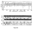
- Figures 6b and 6c provide PA output graphs for APM and FL-APM.
- Figure 6b includes a graph that describes the jitter buffer fill level (buffer utilization) measured for a period of 800 seconds. The jigsaw pattern is due to a 5ppm difference between sender and receiver.
- the lower graphs in each figure show the generated PA, each positive PA marked as one 0 to 1 vertical line, while negative PA is marked as one -1 to 0 vertical line.
- the lower graph marked "APM" indicates the PA generated by the comparator 516 of Figure 5.
- the graph marked "FLPM” shows the PAs generated by PA generator 520 of Figure 5, as configured by FL-APM detector 524 .
- the graph marked “Total PA” indicates the total PA generated by Mux 522 of Figure 5.
- the PAs generated by APM in Figure 6b demonstrate a periodic distribution. The period is similar to the jitter buffer fill level period caused by the 5ppm difference between sender and receiver clocks. This periodic behavior may cause wander (low rate) timing impairments.
- Figure 6c shows the operation of FL-APM under the same conditions.
- the PAs generated in Figure 6c are evenly distributed, and therefore do not generate wander timing impairments.
- APM-generated PAs indicate that comparator 516 (Fig. 5) still generates a small number of positive and negative PAs.
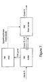
- Figure 7 describes a simplified system with Adaptive Rate Management (ARM) according to the present invention.
- Data clocked by a master clock S is inserted into an apparatus running with slave Clock R.
- Clock S and Clock R are not synchronized, and therefore may have difference average frequencies.
- the incoming data is first inserted into a buffer 702.
- a buffer 702 is jitter buffer 136 of Figure 1.
- An ARM block 706 monitors the fill level of buffer 702, and provides 'Fast', 'Slow', or 'None' rate control commands to a data handler block 704 .
- the data handler block extracts data from buffer 702 at a rate determined by Clock R when the control command received from the ARM block is 'None', at a rate higher than Clock R by a fixed ⁇ D if the control command is 'Fast', or at a rate lower than Clock R by a fixed ⁇ D if the control command is 'Slow'.
- Examples of an ARM system include the APM and FL-APM systems described in Figure 3 and Figure 5, where the 'Fast', 'Slow' and 'None' indicate generation of negative, positive, or no pointer adjustments.
- the data handler provides an output to a SONET mapper or SONET framer as described in Figure 1.
- bit-stuffing controller Another example of an ARM system shown in Figure 7 is a bit-stuffing controller, where the 'Fast', 'Slow' and 'None' commands translate respectively into 'use more opportunity bits than determined by Clock R', 'use less opportunity bits than determined by Clock R' and 'use the opportunity bits as determined by Clock R'.
- Data handler 704 in bit-stuffing controllers would map a lower rate PDH signal into a higher rate one (e.g. a T1 into T3) or to a SONET container (T1 bit-asynchronously mapped into SONET VT1.5 container).
- Figure 8 describes in a block diagram the main steps of a preferred embodiment of an ARM method according to the present invention.
- the APM method described in Figure 2 is an application of the ARM method for the field SONET emulation. ARM can be applied to other applications, one example being bit-stuffing controllers.
- the ARM determines an error E s at sample rate in step 802.
- An example of a sample rate is the circuit emulation arrival rate of circuit emulation packets for the APM method of Figure 2.
- the error E s is the difference between the fill level of buffer 702 of Figure 7 and its optimal level.
- a decimated error E is calculated out of the last N samp error values E s .
- E max s (E s ), i.e. taking the maximum E s sampled on the N samp intervals, as used in step 206 in Figure 2 of the APM method.
- E i in Figure 2
- other functions may be used to calculate the decimated error E from error values E s , including averaging, as well as taking only the last E s value.
- the sample rate is decimated by N samp
- steps 808-816 operate at the decimated rate.
- step 808 the decimated error E is multiplied by a gain G, and in step 810 the result is added to an accumulator A to obtain an updated accumulator value.
- step 812 the updated value of A is compared against the values 1 and -1. If A is smaller than, or equal to -1, ARM issues a 'Slow' command and increments the value of A by 1. If A is larger than, or equal to 1, ARM issues a 'Fast' command and decrements the value of A by 1. Else, ARM issues a 'None' command. Steps 802 and 804 continue to operate at the sample rate, while steps 808-816 continue to operate at the decimated rate.
- the present invention provides a method and system for Adaptive Rate Management that is superior in its flexibility and performance to existing APM methods and systems.
- a simplified ARM system may be used both as an APM system and as a bit-stuffing controller.
- the present invention also provides enhanced APM methods and systems, including a Frequency Locked APM method and system.
- the APM method of the present invention has a number of clear advantages over prior art methods, in that:
- the FL-APM method has additional advantages over prior art methods, in that:
Landscapes
- Engineering & Computer Science (AREA)
- Computer Networks & Wireless Communication (AREA)
- Signal Processing (AREA)
- Computer Hardware Design (AREA)
- Multimedia (AREA)
- Synchronisation In Digital Transmission Systems (AREA)
- Data Exchanges In Wide-Area Networks (AREA)
- Time-Division Multiplex Systems (AREA)
- Communication Control (AREA)
Abstract
Description
According to the present invention there is provided an adaptive pointer management method for accommodating clock frequency differences between a sender having a sender clock and a receiver having a receiver clock, the method comprising the steps of determining an error value Ei at a sample rate; decimating the sample rate by a value Nsamp; determining a decimated error value E as a function of the last Nsamp number of error values Ei; at the decimated rate, obtaining an updated accumulator value based on the decimated error value E; and at the decimated rate, based on the updated accumulator value, generating an appropriate pointer adjustment command and changing the accumulator value, whereby the pointer adjustment command ensures synchronization between the transmitter and receiver rates.
- It stands within the required clock performance requirements
- It has a controlled maximal PA rate (controlled by Nsamp).
- It generates a minimally erroneous PA.
- It is simple to implement in hardware and software.
- It can support multiple channels with a single, simple, and efficient design.
- The same set of parameters is suitable for multiple network conditions and frequency offsets of sender.
- It provides a stable mechanism that can adapt to changes in network conditions, and can adapt to changes of frequency offsets between receiver and sender.
- It distributes the pointer adjustments generated evenly, minimizing the wander and jitter timing impairments.
- It enables APM to converge to the configured operating point, removing the dependency on the frequency offset between sender and receiver.
- It can work with any APM implementation.
Claims (26)
- An adaptive pointer management method for accommodating clock frequency differences between a sender having a sender clock and a receiver having a receiver clock, the method comprising the steps of:a. determining an error value Ei at a sample rate;b. decimating said sample rate by a value Nsamp;c. determining a decimated error value E as a function of a last Nsamp number of said error values Ei;d. at said decimated rate, obtaining an updated accumulator value based on said decimated error value E; ande. at said decimated rate, based on said updated accumulator value, generating an appropriate pointer adjustment command and changing said accumulator value; whereby said pointer adjustment command ensures synchronization between the transmitter and receiver rates.
- The method of claim 1, wherein the receiver and sender are connected over a packet switched network.
- The method of claim 1, wherein said step of determining an error value Ei includes monitoring a jitter buffer fill level Ji each i-th interval having a length I, said length determined by the receiver clock.
- The method of claim 1, wherein said step of computing an error factor Ei includes determining, each i-th interval, an operating point Oi, and subtracting said Oi from said Ji.
- The method of claim 1, wherein said step of determining a decimated error value E includes using a function selected from the group consisting of taking the maximum value of said last Nsamp number of said error values Ei, averaging said Ei, or taking the last value of said Ei.
- The method of claim 1, wherein said step of obtaining an updated accumulator value includes multiplying said decimated error value E by a gain G to obtain an E*G product, and adding said E*G product to an immediately previous said accumulator value.
- The method of claim 1, wherein said step of generating an appropriate pointer adjustment command further includes, if said accumulator value is smaller than or equal to -1, generating a positive pointer adjustment command and incrementing said accumulator value by +1; if said accumulator value is larger than or equal to +1, generating a negative pointer adjustment command and decrementing said accumulator value by -1; and if said accumulator value is greater than -1 and smaller than +1, do nothing.
- An adaptive rate management method for adapting a receiver rate to a transmission rate, the method comprising:whereby said rate adjustment command ensures synchronization between the transmitter and receiver rates.a. determining an error value E; at a sample rate;b. decimating said sample rate by a value Nsamp;c. determining a decimated error value E as a function of the last Nsamp said error values Ei;d. at said decimated rate, obtaining an updated accumulator value based on said decimated error value E; ande. at said decimated rate, based on said updated accumulator value, generating an appropriate rate adjustment command and changing said accumulator value;
- The method of claim 8, wherein the error value Ei is determined by monitoring a jitter buffer fill level J; each i-th interval having a length I, said length determined by the receiver clock;
- The method of claim 8, wherein said step of computing an error factor Ei includes determining, each i-th interval, an operating point Oi, and subtracting said Oi from said Ji.
- The method of claim 8, wherein said decimated error value is obtained using a function selected from the group consisting of taking the maximum value of said last Nsamp number of said error values Ei, averaging said Ei, or taking the last value of said Ei.
- The method of claim 8, wherein said step of obtaining an updated accumulator value includes multiplying said decimated error value E by a gain G to obtain an E*G product, and adding said E*G product to a previous said accumulator value.
- The method of claim 8, wherein said step of generating an appropriate rate adjustment command further includes, if said accumulator value is smaller than or equal to -1, generating a 'slow' rate command and incrementing said accumulator value by +1, if said accumulator value is larger than or equal to +1, generating a 'fast' rate command and decrementing said accumulator value by -1, and if said accumulator value is greater than -1 and smaller than +1, generating a 'none' rate command.
- A frequency locked adaptive pointer management method comprising the steps of:a. obtaining a plurality of pointer adjustments generated in an interval i by an adaptive pointer management technique;b. based on said plurality of pointer adjustments, calculating a long term average value PAavg(i+1) of pointer adjustments to be generated in an immediately following interval i+1; andc. in said immediately following interval i+1, generating appropriate pointer adjustments at a constant rate based on said PAavg(i+1).
- The method of claim 14, wherein said step of obtaining a plurality of pointer adjustments includes counting the number of positive pointer adjustments PA+(i) and negative pointer adjustments PA-(i) generated in said interval i, and wherein said step of calculating PAavg(i+1) includes calculating an average pointer adjustment value PAavg(i) of said positive and negative pointer adjustments, and using said PAavg(i) to calculate said PAavg(i+1).
- The method of claim 15, wherein said step of calculating a long term average value PAavg(i+1) includes obtaining a gain factor G, and calculating said PAavg(i+1) according to the formula PAavg(i+1) = (1-G)* PAavg(i) + G*(PA+(i) - PA-(i)).
- The method of claim 16, wherein said step of generating appropriate pointer adjustments at a constant rate includes generating a number of PAavg(i) positive pointer adjustments if said PAavg(i) is greater than zero, and generating a number of PAavg(i) negative pointer adjustments if said PAavg(i) is smaller than zero.
- A frequency locked adaptive rate management method comprising the steps of:a. obtaining a plurality of rate commands generated in an interval i by an adaptive rate management technique;b. based on said plurality of rate commands, calculating a long term average value PAavg(i+1) of rate commands to be generated in an immediately following interval i+1; andc. in said immediately following interval i+1, generating appropriate rate commands at a constant rate based on said PAavg(i+1).
- The method of claim 18, wherein said step of obtaining a plurality of rate commands includes counting the number of 'slow' rate commands PA+(i) and 'fast' negative rate commands PA-(i) generated in said interval i, and wherein said step of calculating PAavg(i+1) includes calculating an average pointer adjustment value PAavg(i) of said 'slow' and 'fast' rate commands, and using said PAavg(i) to calculate said PAavg(i+1).
- The method of claim 19, wherein said step of calculating a long term average value PAavg(i+1) includes obtaining a gain factor G, and calculating said PAavg(i+1) according to the formula PAavg(i+1) = (1-G)* PAavg(i) + G*(PA+(i) - PA-(i)).
- The method of claim 20, wherein said step of generating appropriate rate commands at a constant rate includes generating a number of PAavg(i) 'slow' rate commands if said PAavg(i) is greater than zero, and generating a number of PAavg(i) 'fast' rate commands if said PAavg(i) is smaller than zero.
- A system for synchronizing a receiver clock and a sender clock, one each at two terminal ends of a transmission network, the system comprising:a. sampling means to periodically sample, of each channel of the transmission network, an input jitter buffer fill level and to generate an error factor for said channel;b. configuration means to generate configuration parameters that include a gain factor, a rate decimation factor Nsamp, and an operating point O.c. pointer adjustment generator means for generating negative and positive pointer adjustments using said gain factor and said error factor, said pointer adjustments providing the required synchronization of the clocks.
- The system of claim 22, wherein said sampling means include:i. a sampler operative to receive a number of Nsamp said configuration parameters from said configuration means;ii. a sampling rate generator for periodically activating said sampler;iii. a detector for performing said sampling in response to triggers received from said sampler and said sampling generator, said sampling used to obtain periodic errors, said periodic errors used and for said generating of said error factor;
and wherein said pointer adjustment generator means include:iv. a multiplier for multiplying said error factor and said gain factor to obtain a gain*error product;v. an accumulator for providing an updated accumulator value based on said gain*error product; andvi. a comparator for comparing said updated accumulator value with a threshold, and for performing said generation of pointer adjustments based on said comparison. - The system of claim 22 further comprising, for each said channel, pointer adjustment counters communicating with said pointer adjustment generator means.
- A system for providing efficient pointer adjustments that synchronize a slave clock to a master clock located at two different terminal ends of a transmission network, the system comprising:a. adaptive pointer management means for providing, per interval i, a first plurality of negative pointer adjustments and a second plurality of positive pointer adjustments;b. averaging means for producing a long term average of pointer adjustments per said interval i, using said pluralities of pointer adjustments; andc. pointer adjustment generating means for generating pointer adjustments at a constant rate each said interval i, based on said long term average.
- A system for synchronizing the rates of a transmitter and a receiver, one each at two terminal ends of a transmission network, the system comprising:a. sampling means to periodically sample, of each channel of the transmission network, an input jitter buffer fill level and to generate an error factor for said channel;b. configuration means to generate configuration parameters that include a gain factor; andc. rate adjustment means for generating commands based on said error factor and said gain factor, said commands providing the required rate synchronization.
Applications Claiming Priority (2)
| Application Number | Priority Date | Filing Date | Title |
|---|---|---|---|
| US47388003P | 2003-05-29 | 2003-05-29 | |
| US473880P | 2003-05-29 |
Publications (3)
| Publication Number | Publication Date |
|---|---|
| EP1482665A2 true EP1482665A2 (en) | 2004-12-01 |
| EP1482665A9 EP1482665A9 (en) | 2005-03-16 |
| EP1482665A3 EP1482665A3 (en) | 2006-08-23 |
Family
ID=33131953
Family Applications (1)
| Application Number | Title | Priority Date | Filing Date |
|---|---|---|---|
| EP04291346A Withdrawn EP1482665A3 (en) | 2003-05-29 | 2004-05-28 | Methods and systems for adaptive rate management, for adaptive pointer management, and for frequency locked adaptive pointer management |
Country Status (3)
| Country | Link |
|---|---|
| US (1) | US7436858B2 (en) |
| EP (1) | EP1482665A3 (en) |
| JP (1) | JP2004364293A (en) |
Cited By (1)
| Publication number | Priority date | Publication date | Assignee | Title |
|---|---|---|---|---|
| EP2613473A3 (en) * | 2006-02-13 | 2013-10-09 | Belair Networks Inc. | System and method for packet timing of circuit emulation services over networks |
Families Citing this family (27)
| Publication number | Priority date | Publication date | Assignee | Title |
|---|---|---|---|---|
| FR2872654B1 (en) * | 2004-06-30 | 2006-09-08 | Alcatel Sa | METHOD FOR RE-SYNCHRONIZING FLOWS BENEFITING FROM CIRCUIT EMULATION SERVICES FOR A PACKET SWITCHED COMMUNICATIONS NETWORK |
| US20080219669A1 (en) * | 2007-03-05 | 2008-09-11 | Futurewei Technologies, Inc. | SDH/SONET Convergent Network |
| FI120284B (en) * | 2007-07-20 | 2009-08-31 | Tellabs Oy | Control of the fill rate in a jitter buffer |
| US8625621B2 (en) * | 2008-03-06 | 2014-01-07 | Integrated Device Technology, Inc. | Method to support flexible data transport on serial protocols |
| US20090228733A1 (en) * | 2008-03-06 | 2009-09-10 | Integrated Device Technology, Inc. | Power Management On sRIO Endpoint |
| US8213448B2 (en) * | 2008-03-06 | 2012-07-03 | Integrated Device Technology, Inc. | Method to support lossless real time data sampling and processing on rapid I/O end-point |
| US8312241B2 (en) * | 2008-03-06 | 2012-11-13 | Integrated Device Technology, Inc. | Serial buffer to support request packets with out of order response packets |
| US20090225775A1 (en) * | 2008-03-06 | 2009-09-10 | Integrated Device Technology, Inc. | Serial Buffer To Support Reliable Connection Between Rapid I/O End-Point And FPGA Lite-Weight Protocols |
| US8312190B2 (en) * | 2008-03-06 | 2012-11-13 | Integrated Device Technology, Inc. | Protocol translation in a serial buffer |
| US8416813B1 (en) * | 2009-04-29 | 2013-04-09 | Tellabs Operations, Inc. | Methods and apparatus for clocking domain discovery in multi-domain networks |
| US8503458B1 (en) * | 2009-04-29 | 2013-08-06 | Tellabs Operations, Inc. | Methods and apparatus for characterizing adaptive clocking domains in multi-domain networks |
| US20110144969A1 (en) * | 2009-12-11 | 2011-06-16 | International Business Machines Corporation | High-Frequency Entropy Extraction From Timing Jitter |
| KR101749064B1 (en) * | 2011-03-24 | 2017-06-20 | 삼성전자주식회사 | Method and apparatus of sensor network supporting bidirectional event detection |
| CN103780338A (en) * | 2012-10-26 | 2014-05-07 | Lsi公司 | Connector between asynchronization virtual container passageway and a high data speed port |
| US9066153B2 (en) | 2013-03-15 | 2015-06-23 | Time Warner Cable Enterprises Llc | Apparatus and methods for multicast delivery of content in a content delivery network |
| US10368255B2 (en) | 2017-07-25 | 2019-07-30 | Time Warner Cable Enterprises Llc | Methods and apparatus for client-based dynamic control of connections to co-existing radio access networks |
| US11540148B2 (en) | 2014-06-11 | 2022-12-27 | Time Warner Cable Enterprises Llc | Methods and apparatus for access point location |
| US10327187B2 (en) | 2015-12-04 | 2019-06-18 | Time Warner Cable Enterprises Llc | Apparatus and method for wireless network extensibility and enhancement |
| US9986578B2 (en) | 2015-12-04 | 2018-05-29 | Time Warner Cable Enterprises Llc | Apparatus and methods for selective data network access |
| US9918345B2 (en) | 2016-01-20 | 2018-03-13 | Time Warner Cable Enterprises Llc | Apparatus and method for wireless network services in moving vehicles |
| US10492034B2 (en) | 2016-03-07 | 2019-11-26 | Time Warner Cable Enterprises Llc | Apparatus and methods for dynamic open-access networks |
| US10164858B2 (en) | 2016-06-15 | 2018-12-25 | Time Warner Cable Enterprises Llc | Apparatus and methods for monitoring and diagnosing a wireless network |
| US10645547B2 (en) | 2017-06-02 | 2020-05-05 | Charter Communications Operating, Llc | Apparatus and methods for providing wireless service in a venue |
| US10638361B2 (en) | 2017-06-06 | 2020-04-28 | Charter Communications Operating, Llc | Methods and apparatus for dynamic control of connections to co-existing radio access networks |
| CN112134651B (en) * | 2017-09-21 | 2023-05-09 | 中国移动通信有限公司研究院 | OAM message transmission method, transmission equipment and storage medium |
| US10884954B2 (en) * | 2018-09-17 | 2021-01-05 | Silicon Motion, Inc. | Method for performing adaptive locking range management, associated data storage device and controller thereof |
| CN114528226A (en) | 2018-09-17 | 2022-05-24 | 慧荣科技股份有限公司 | High-efficiency garbage collection method, data storage device and controller thereof |
Family Cites Families (7)
| Publication number | Priority date | Publication date | Assignee | Title |
|---|---|---|---|---|
| US5025457A (en) * | 1989-04-21 | 1991-06-18 | Codex Corporation | Synchronizing continuous bit stream oriented terminals in a communications network |
| DE69227820T2 (en) * | 1991-10-10 | 1999-05-12 | Nec Corp., Tokio/Tokyo | Sonet DS-N desynchronizer |
| US5396492A (en) * | 1993-04-28 | 1995-03-07 | At&T Corp. | Method and apparatus for adaptive clock recovery |
| GB9410943D0 (en) * | 1994-06-01 | 1994-07-20 | Newbridge Networks Corp | Clock recovery unit |
| WO1999008409A1 (en) * | 1997-08-06 | 1999-02-18 | Telefonaktiebolaget Lm Ericsson | A method and an apparatus for the clock recovery in the transport of constant bit rate services over asynchronous transfer mode |
| US6721328B1 (en) * | 1999-11-19 | 2004-04-13 | Adc Telecommunications, Inc. | Adaptive clock recovery for circuit emulation service |
| AUPQ896300A0 (en) * | 2000-07-24 | 2000-08-17 | Nec Australia Pty Ltd | A clock synchronisation method for usb sink devices |
-
2004
- 2004-05-28 JP JP2004160144A patent/JP2004364293A/en active Pending
- 2004-05-28 EP EP04291346A patent/EP1482665A3/en not_active Withdrawn
- 2004-06-01 US US10/856,788 patent/US7436858B2/en not_active Expired - Fee Related
Cited By (1)
| Publication number | Priority date | Publication date | Assignee | Title |
|---|---|---|---|---|
| EP2613473A3 (en) * | 2006-02-13 | 2013-10-09 | Belair Networks Inc. | System and method for packet timing of circuit emulation services over networks |
Also Published As
| Publication number | Publication date |
|---|---|
| US7436858B2 (en) | 2008-10-14 |
| US20040240478A1 (en) | 2004-12-02 |
| EP1482665A3 (en) | 2006-08-23 |
| EP1482665A9 (en) | 2005-03-16 |
| JP2004364293A (en) | 2004-12-24 |
Similar Documents
| Publication | Publication Date | Title |
|---|---|---|
| US7436858B2 (en) | Methods and systems for adaptive rate management, for adaptive pointer management, and for frequency locked adaptive pointer management | |
| EP2381622B1 (en) | Update of a cumulative residence time of a packet in a packet-switched communication network | |
| EP1455473B1 (en) | Clock Synchronisation over a Packet Network | |
| US8018968B2 (en) | System and method for high precision clock recovery over packet networks | |
| US11239933B2 (en) | Systems and methods for transporting constant bit rate client signals over a packet transport network | |
| EP1109349A2 (en) | Clock recovery pll for ATM networks | |
| US20030021287A1 (en) | Communicating data between TDM and packet based networks | |
| US5844891A (en) | Cell-based clock recovery device | |
| EP1394975A2 (en) | Adaptive Clock Recovery | |
| CN109039514B (en) | Method for improving IEEE1588 timestamp precision | |
| EP1436923B1 (en) | Method and apparatus for digital data synchronization | |
| US7305013B2 (en) | Handling traffic in a synchronous communication network | |
| CA2472691C (en) | Digital processing of sonet pointers | |
| US7457390B2 (en) | Timeshared jitter attenuator in multi-channel mapping applications | |
| GB2392589A (en) | Adaptive clock recovery using a packet delay variation buffer and packet count | |
| US7715443B1 (en) | Boundary processing between a synchronous network and a plesiochronous network | |
| WO2002091642A2 (en) | Communicating data between tdm and packet based networks | |
| EP1384341A2 (en) | Communicating data between tdm and packet based networks | |
| WO2007124649A1 (en) | Bit leak control method and system |
Legal Events
| Date | Code | Title | Description |
|---|---|---|---|
| PUAI | Public reference made under article 153(3) epc to a published international application that has entered the european phase |
Free format text: ORIGINAL CODE: 0009012 |
|
| AK | Designated contracting states |
Kind code of ref document: A2 Designated state(s): AT BE BG CH CY CZ DE DK EE ES FI FR GB GR HU IE IT LI LU MC NL PL PT RO SE SI SK TR |
|
| AX | Request for extension of the european patent |
Extension state: AL HR LT LV MK |
|
| PUAL | Search report despatched |
Free format text: ORIGINAL CODE: 0009013 |
|
| AK | Designated contracting states |
Kind code of ref document: A3 Designated state(s): AT BE BG CH CY CZ DE DK EE ES FI FR GB GR HU IE IT LI LU MC NL PL PT RO SE SI SK TR |
|
| AX | Request for extension of the european patent |
Extension state: AL HR LT LV MK |
|
| AKX | Designation fees paid |
Designated state(s): AT BE BG CH CY CZ DE DK EE ES FI FR GB GR HU IE IT LI LU MC NL PL PT RO SE SI SK TR |
|
| STAA | Information on the status of an ep patent application or granted ep patent |
Free format text: STATUS: THE APPLICATION IS DEEMED TO BE WITHDRAWN |
|
| 18D | Application deemed to be withdrawn |
Effective date: 20061201 |