EP1482656A2 - Adaptive controller and adaptive control method that can adaptively control a plurality of variable high frequency devices at high speed - Google Patents
Adaptive controller and adaptive control method that can adaptively control a plurality of variable high frequency devices at high speed Download PDFInfo
- Publication number
- EP1482656A2 EP1482656A2 EP04006553A EP04006553A EP1482656A2 EP 1482656 A2 EP1482656 A2 EP 1482656A2 EP 04006553 A EP04006553 A EP 04006553A EP 04006553 A EP04006553 A EP 04006553A EP 1482656 A2 EP1482656 A2 EP 1482656A2
- Authority
- EP
- European Patent Office
- Prior art keywords
- high frequency
- variable high
- impedance
- frequency devices
- varied
- Prior art date
- Legal status (The legal status is an assumption and is not a legal conclusion. Google has not performed a legal analysis and makes no representation as to the accuracy of the status listed.)
- Granted
Links
Images


Classifications
-
- G—PHYSICS
- G05—CONTROLLING; REGULATING
- G05B—CONTROL OR REGULATING SYSTEMS IN GENERAL; FUNCTIONAL ELEMENTS OF SUCH SYSTEMS; MONITORING OR TESTING ARRANGEMENTS FOR SUCH SYSTEMS OR ELEMENTS
- G05B13/00—Adaptive control systems, i.e. systems automatically adjusting themselves to have a performance which is optimum according to some preassigned criterion
- G05B13/02—Adaptive control systems, i.e. systems automatically adjusting themselves to have a performance which is optimum according to some preassigned criterion electric
- G05B13/0205—Adaptive control systems, i.e. systems automatically adjusting themselves to have a performance which is optimum according to some preassigned criterion electric not using a model or a simulator of the controlled system
- G05B13/024—Adaptive control systems, i.e. systems automatically adjusting themselves to have a performance which is optimum according to some preassigned criterion electric not using a model or a simulator of the controlled system in which a parameter or coefficient is automatically adjusted to optimise the performance
Definitions
- the present invention generally relates to adaptive control, and more particularly, to an adaptive controller and an adaptive control method for adaptively controlling at high speed a plurality of variable high frequency devices (hereinafter, the "variable high frequency devices” refers to high frequency devices whose impedances are variable).
- each impedance is adaptively controlled to an optimum value.
- good wireless communication is performed by adaptively controlling impedances of high frequency devices such as capacitors and inductors associated with a plurality of antenna elements.
- FIG. 1 shows such an adaptive control system.
- each of M antenna elements 102 is connected to a high frequency device 104.
- High frequency devices 104 are capable of varying the respective impedances z 1 through z 2M in accordance with control signals x 1 through x 2M .
- the M antenna elements 102 are connected to a combiner 106.
- the output of the combiner 106 is supplied to an adaptive controller 108. Signals received by the respective antenna elements 102 are combined under influences of the impedances z 1 through z 2M of the respective high frequency devices 104 and are introduced in the adaptive controller 108.
- the control signals x 1 through x 2M are created such that a signal from the combiner 106 has a desired characteristic, thereby varying the respective impedances. Hence, it becomes possible to suppress only interference waves and process only desired waves in the subsequent stages among a plurality of arriving waves that are received by the antenna elements 102.
- FIG. 2 shows a conventional control flow 200 that can be used in an adaptive controller.
- the method is an optimizing method using a perturbation method.
- the control flow 200 starts in step 202.
- impedances z i of a plurality of elements (inductors L i and capacitors C i ) or control signals x i for setting them are set to appropriate initial values.
- the value of a parameter m for indicating an element that is subject to control is set to an initial value 0.
- the value of the evaluation function f(z) is stored in a memory as a reference value fo(z).
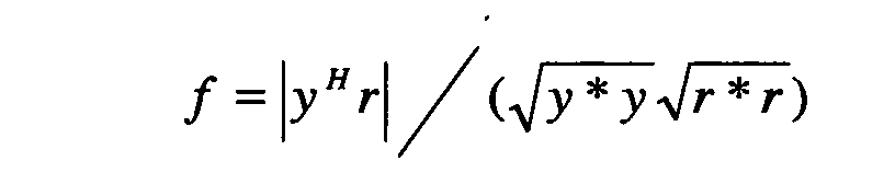
- Various functions may be adopted as the evaluation function f(z). It is possible, for example, to adopt a function representing the coincidence of received signals y and known signals (preambles) r that are inserted into a transmission signal at regular intervals as follows. In this case, H represents obtaining an Hermitian conjugate (to obtain a complex conjugate by transposing a vector).
- the value of the function f(z) is a real value having the absolute value of 1 or less: when the received signal y and the known signal r match, the value of the function f(z) is 1, and when the received signal y and the known signal r are orthogonal, the value of the function f(z) is 0.
- step 210 the value of the parameter m is incremented by 1.
- step 212 the value of impedance z m of the "m" th element is varied to z m + ⁇ z m .
- the value of "m" is 1, for example, the value of an inductor L 1 is slightly varied. The slight variation ⁇ z m in the impedance z m results in variation in the output signal y(z).
- step 214 the value of the evaluation function E f(z) is calculated by using the frame next to the frame used in the calculation in step 208.
- a gradient vector ⁇ f is calculated by calculating the difference between the values of the evaluation function f(z) before and after the variation with respect to the impedance z m .
- step 2128 the value of the slightly varied z m is returned to the value before the slight variation.
- step 220 it is determined whether the value of the parameter m is 2M or less. When the value of the parameter m is 2M or less (YES in step 220), the flow returns to step 208, and another component of the gradient vector ⁇ f is calculated. On the other hand, when the value of the parameter m is not 2M or less (NO in step 220), i.e., greater than 2M, which means all components of the gradient vector ⁇ f are calculated, the flow proceeds to step 222.
- step 222 the value of the impedance z i of each element is updated by using the gradient vector ⁇ f.
- the gradient vector ⁇ f indicates the direction in which the gradient (inclination) is most drastically varied from a coordinate (z1, z2, ..., z2M) on an f surface. Accordingly, it is possible to approach the maximum or minimum value (a desired optimum value) of the evaluation function f(z) by advancing in the direction indicated by ⁇ f from the coordinate.
- a parameter ⁇ represents the step width in advancing along ⁇ f when updating the value of the impedance z i . In the aforementioned manner, the value of the impedance z i is updated.
- step 224 it is determined whether sufficient convergence is obtained by comparing the value of the previous impedance with that of the updated impedance. When sufficient convergence is not obtained (NO in step 224), the flow returns to step 206. When sufficient convergence is obtained (YES in 224), the flow proceeds to step 226 where the control flow 200 ends.
- the high frequency devices 104 which are used in conventional adaptive control systems, are generally formed by semiconductor devices such as varactor diodes in light of high-speed operations. It is possible to cause such a kind of semiconductor devices to perform a vary high speed operation, i.e., to vary the impedance in a very short time interval, for example, in 10 -12 seconds. However, such semiconductor devices have a problem in that comparatively a great deal of electric power is consumed. In addition, such semiconductor devices have problems in that insertion loss may be high, isolation characteristics may be low, and cost may be high, for example. Accordingly, it is not easy to perform adaptive control as mentioned above by mounting such a kind of semiconductor devices on a small electronic device.
- An Electro Mechanical System in the order of micrometers or nanometers is a minute mechanical system having a size of approximately micrometers or nanometers. It is possible to build a variable high frequency device using an EMS by, for example, mechanically varying the distance between the polar plates of a capacitor or by varying the insertion amount of a magnetic core of an inductor. Variable high frequency devices or variable impedance devices using EMSs are advantageous in isolation characteristics, insertion loss, costs, and the like, as well as in having an electric power consumption less than that of semiconductor devices, which mainly results from mechanical operations thereof.
- variable high frequency devices using EMSs it is necessary for variable high frequency devices using EMSs to move moving parts thereof so as to vary impedance. For this reason, such variable high frequency devices are disadvantageous in that the working speed thereof is slower than that of semiconductor devices.
- the high frequency device 104 is formed by four elements each using an EMS, and each of the elements requires 100 ⁇ s to vary the impedance, for example.
- the high frequency element 104 is formed by four elements each using an EMS and being capable of varying the impedance at a comparatively high speed such as 4 ⁇ s, though which speed is slower than that of semiconductor devices.
- a comparatively high speed such as 4 ⁇ s
- it is possible to perform the update of impedance in step 222 once in (twice ⁇ 4 elements + 1 (for updating)) ⁇ 4 ⁇ s 36 ⁇ s.
- the calculations of the value of the evaluation function in steps 208 and 214 use the known signals included in frames. Thus, it is not always possible to update the impedance at high speed as such.
- a general object of the present invention is to provide an improved and useful adaptive controller and adaptive control method in which one or more of the above-mentioned problems are eliminated.
- Another and more specific object of the present invention is to provide an adaptive controller and an adaptive control method that can adaptively control at high speed a plurality of variable high frequency devices (high frequency devices whose impedances are variable) formed by Electro Mechanical Systems.
- Still another object of the present invention is to provide an adaptive controller and an adaptive control method that can adaptively control at high speed a plurality of variable high frequency devices formed by Electro Mechanical Systems by using payloads following preambles in frames.
- an adaptive controller for adaptively controlling a plurality of variable high frequency devices, the adaptive controller including:
- FIG. 3 is a block diagram relating to major functions of an adaptive controller 300 according to one embodiment of the present invention.
- the adaptive controller 300 may be used instead of, for example, the adaptive controller 108 shown in FIG. 1.
- the present invention may be applied not only to such adaptive array antenna systems but also to arbitrary non-linear systems that adaptively control a plurality of variable high frequency devices (the "variable high frequency devices" refers to high frequency devices whose impedances are variable).
- the total number of variable high frequency devices that are subject to control is M, and the digital received signal y(z) from the combiner 106 is input to the adaptive controller 300.
- the adaptive controller 300 includes a calculation part 302.
- the calculation part 302 receives the digital received signal y(z), and calculates the value of a predetermined evaluation function E(n).
- the known signal is a signal that is predetermined in a transmitting source and a receiving end.
- FIG. 4 shows a signal format used in this embodiment.
- the signal format includes successive frames. For convenience of explanation, it is assumed that a frame of 20 ⁇ s includes 5 symbols of 4 ⁇ s; 2 symbols are allocated to a preamble (8 ⁇ s), and the subsequent 3 symbols are allocated to a payload.
- the above-mentioned known signal is inserted into the preamble of a transmission signal employing the signal format.
- various forms may be adopted as the form of the evaluation function E that is calculated in the calculation part 302.
- the inner product of a standardized received signal and a known signal which is used in steps 208 and 214 in FIG. 2, is used as the evaluation function E.
- the evaluation function E is varied depending on the number (n) of frames and an impedance vector z(n). It is also possible to use, for example, the absolute value of the difference between the received signal and the known signal as another form of the evaluation function E.
- the adaptive controller 300 also includes a determination part 304 connected to an output of the calculation part 302.
- the determination part 304 determines the direction (increasing direction or decreasing direction) in which the scalar function value is varied.
- the determination part 304 determines whether the variation of the scalar function value is in the increasing direction or the decreasing direction.
- the determination method includes various methods. It is possible to accurately determine the variation direction by determining whether sequentially obtained K scalar function values are continuously increased or decreased, for example.
- the adaptive controller 300 also includes an impedance variation part 306 connected to an output of the determination part 304.
- the impedance variation part 306 creates signals for varying the impedances of the variable high frequency devices.
- the impedance variation part 306 includes a first variation part 308 that further varies the impedances of the variable high frequency devices in the same direction in accordance with a determination result in the determination part 304. That is, if a variation in the scalar function value calculated in the calculation part 302 results from increasing the impedance z i of a given variable high frequency device, the first variation part 308 creates a control signal that further increases the impedance z i of the variable high frequency device under a specific condition (that is described later).
- the first variation part 308 creates a control signal that further decreases the impedance z i of the variable high frequency device under a specific condition.
- the impedance variation part 306 also includes a second variation part 310'.
- the second variation part 310 varies the impedance of a variable high frequency device in an oppositely sloped direction (for example, in a negatively sloped (decreasing) direction from a positively sloped (increasing) direction, or in a positively sloped direction from a negatively sloped direction as shown in FIGS. 6 and 9, described later) or varies the impedance of another variable high frequency device.
- the second variation part 310 When a variation in the scalar function value calculated in the calculation part 302 results from increasing (or decreasing) the impedance z i of a given variable high frequency device, for example, the second variation part 310 creates a control signal that decreases (or increases) the impedance z i of the variable high frequency device under a specific condition (that is described later). Further, in accordance with the determination result in the determination part 304, the second variation part 310 creates a signal that varies the impedance z i+1 of another variable high frequency device (that is different from the given variable high frequency device) under the specific conditions.
- the adaptive controller 300 also includes a step size adjusting part 312. Based on information (especially a frame number n) obtained from the calculation part 302, the step size adjusting part 312 properly adjusts a variation amount ⁇ z i (n) of impedance in the impedance variation part 306.
- the adaptive controller 300 also includes a digital/analog converter (D/A) (signal form conversion means) 314 connected to an output of the impedance variation part 306.
- D/A digital/analog converter
- the digital/analog converter converts a digital signal from the impedance variation part 306 to an analog signal.
- the adaptive controller 300 also includes a selection part 316 connected to an output of the digital/analog converter 314.
- the variable high frequency device that receives the control signal x i adjusts the impedance value thereof by mechanically moving a moving part thereof in accordance with the contents of the received control signal x i .
- FIG. 5 is a flow chart showing a control flow 500 of an adaptive control system according to one embodiment of the present invention.
- the impedance of each element is adaptively controlled such that the evaluation function E is minimized.
- control for obtaining the maximum value of the evaluation function E may be performed.
- the present invention may be applied to a system that not only maximizes a value of an evaluation function but also minimizes the value of the evaluation function.
- the number of elements that are subject to control may be an arbitrary number.
- the value of the increase/decrease counter in this embodiment is 0, 1, or 2.
- the impedance of a currently designated variable high frequency device is increased by a predetermined amount.
- the variation of the impedance may be a constant value that is not dependent on the frame number n, or a value that is dependent on the frame number n. Additionally, the variation of the impedance may be an identical value with respect to all variable high frequency devices, or a different value for each variable high frequency device. In any case, the variation of the impedance is properly set in the step size adjusting part 312 (FIG. 3). In a case where both magnitude (absolute value) and phase of the impedance are varied, it is necessary to separately set and adjust the variations thereof. For simplicity, it is assumed that the variation ⁇ z m of impedance in this embodiment is a constant value that is not dependent on the variable high frequency devices and frames, and does not include a phase component.
- step 512 the frame number n is increased (incremented).
- step 514 the value of the evaluation function E is calculated.
- m 1
- the impedance z 1 of the first device is varied by ⁇ zm in the plus direction. Resulting from this impedance variation, a digital received signal that is input to the calculation part 302 (FIG. 3) is also varied.
- the value of the evaluation function E is calculated. It should be noted that the frame number n is updated in step 512 since a preamble inserted in each frame is used for calculating the value of the evaluation function E.
- step 516 it is determined whether the value of the evaluation function is varied in a predetermined desired direction.
- the impedance of each variable high frequency device is varied such that the value of the evaluation function E is minimized.
- the desired direction is the direction in which the value of the evaluation function E is decreased.
- step 516 it is determined whether the value of the evaluation function E is varied in the direction oppositely sloped with respect to the predetermined desired direction. Hence, in step 516, whether the value of the evaluation function E is increased is determined for K times in series. Specifically, whether or not E(n) > E(n - 1) > ... E(n - K) is satisfied is determined.
- step 518 it is determined whether the value c of the increase/decrease counter is 1.
- steps 510 through 516 are performed: the impedance z 1 of a target variable high frequency device is increased in step 510, the frame number n is updated in step 512, the value of the evaluation function E is calculated in step 514, and whether the condition (A) is satisfied is determined in step 516. That is, as indicated by an arrow 530, the impedance z 1 of the variable high frequency device is continuously increased until the condition (A) is satisfied.
- the condition (A) is satisfied in step 516 (when the value of the evaluation function E is increased twice in a consecutive manner)(YES in step 516)
- the flow proceeds to step 522.
- step 520 contrary to step 510, the impedance of the variable high frequency device is varied in the minus direction. Similarly to step 510, the step size adjusting part 312 properly adjusts how much the impedance is decreased. For simplicity, it is assumed that the variation ⁇ z m of the impedance in this embodiment is a constant value irrespective of devices or frames. Then, the flow returns to step 512, where the frame number n is updated. The value of the evaluation function E is calculated in step 514, and the variation direction of the value of the evaluation function E is determined in step 516. When the value of the evaluation function E is decreased by the operation in step 520, the condition (A) is not satisfied. Thus, the flow proceeds to step 518.
- step 518 it is determined whether the value of the increase/decrease counter is 1. In the current case, the decision result in step 518 is YES, and the process proceeds to step 520. Then, similarly, steps 520 through 516 are performed: the impedance of the variable high frequency device is decreased in step 520, the frame number n is updated in step 512, the value of the evaluation function E is calculated in step 514, and the variation direction of the value of the evaluation function E is determined in step 516. That is, as indicated by an arrow 532, the impedance of the variable high frequency device is continuously decreased until the condition (A) is satisfied (until the value of the evaluation function E is increased twice in a consecutive manner). When the condition (A) is satisfied (YES in step 516), the flow proceeds to step 522.
- step 522 the value of the increase/decrease counter is further incremented by 1.
- step 524 it is determined whether the value of the increase/decrease counter is 2. In the current case, the decision result in step 524 is YES. Thus, the process proceeds to step 526.
- step 528 it is determined whether the current value of m is the maximum value M or less. When the value of m is the maximum value M or less (YES in step 528), the flow returns to step 508. As in the case of the impedance z 1 of the variable high frequency device, an impedance z 2 of another variable high frequency device is increased and then decreased. When impedances of all variable high frequency devices are varied, m becomes larger than M (NO in step 528), and the flow proceeds to step 506. In step 506, the number of devices is reset to 1. Thereafter, a similar control procedure is performed. In the aforementioned manner, the impedance of each variable high frequency device is adaptively adjusted.
- a procedure for ending the control flow 500 is omitted from the flow chart shown in FIG. 5.
- the ending procedure it is possible to end the control flow 500 when the value of the evaluation function E becomes smaller than a predetermined value, for example.
- the adaptive control system enters an operation mode in which the value of the evaluation function E is monitored.
- the control flow 500 may be resumed when the value of the evaluation function E becomes larger than a predetermined value, for example.
- FIG. 6 shows states where the impedance z i (the upper portion of FIG. 6) and the value of the evaluation function E (the lower portion of FIG. 6) are varied in accordance with the control flow 500.
- the horizontal axis represents time or the number of frames.
- the impedance of the first variable high frequency device is increased from time 0.
- time t 1 as the impedance z i is increased, the evaluation function E is also varied in the decreasing direction (a desired direction). Thereafter, the impedance z 1 is continuously increased until the evaluation function E is increased twice in a consecutive manner.
- Such a process relates to the loop indicated by the arrow 530 shown in FIG. 5.
- the evaluation function E is increased twice in a consecutive manner.
- the value of the increase/decrease counter is increased, and the value of the impedance z 1 is decreased. Also in this case, the impedance z 1 is decreased until the evaluation function E is increased twice in a consecutive manner.
- Such a process relates to the loop indicated by the arrow 532 shown in FIG. 5.
- FIG. 7 shows time points at which impedance is updated according to this embodiment.
- a frame of 20 ⁇ s includes 5 symbols of 4 ⁇ s: 2 symbols are allocated to a preamble (8 ⁇ s), and the subsequent 3 symbols (12 ⁇ s) are allocated to a payload.
- Known signals are inserted in preambles (hatched parts in FIG. 7) of a transmission signal.
- a variable high frequency device includes a capacitor or an inductor using Electro Micro System (EMS), and the EMS is capable of varying impedance fast in approximately 4 ⁇ s.
- the evaluation function E is calculated every time a preamble is obtained.
- time points at which impedance is updated are the time point at which a first symbol ends, the time point at which a second symbol ends, ..., and it is possible to update the impedance twice for each frame of 20 ⁇ s. Accordingly, it is possible to update impedance for 18 times with respect to 9 frames.
- the impedances of the four devices are updated at a time at the rate of once in 180 ⁇ s (9 frames) as mentioned above.
- the evaluation function E is calculated every time a preamble arrives (for each frame) and impedance of a variable high frequency device is varied.
- impedance of a variable high frequency device is varied.
- step 808 the frame number n is incremented by 1.
- step 810 it is determined whether the value c of the increase/decrease counter is 0.
- the value c of the increase/decrease counter in this embodiment is 0 or 1.
- step 812 the impedance of a variable high frequency device that is currently being designated is increased by a predetermined amount that is set in the step size adjusting part 312 (FIG. 3).
- the variation ⁇ z m of the impedance in this embodiment is a constant value irrespective of variable high frequency devices and frames.
- step 814 the value of the evaluation function E is calculated.
- the impedance of the first variable high frequency device is varied by ⁇ z m . Resulting from this impedance variation, a digital received signal is also varied, and the value of the evaluation function E at this time is calculated.
- step 820 it is determined whether the current value of m is less than the maximum value M.
- the flow returns to step 808, and the impedance z 2 of another variable high frequency device is increased as in the case of the impedance z 1 of the variable high frequency device.
- the value of m becomes larger than the maximum value M (NO in step 820). In such case, the flow proceeds to step 822.
- step 824 it is determined whether the value c of the increase/decrease counter is equal to 1.
- the flow proceeds directly to step 806.
- Step 825 which is a selective step, is described later.
- step 808 the frame number n is updated.
- step 828 the impedance of the variable high frequency device that is currently being designated is decreased for a predetermined amount that is set in the step size adjusting part 312 (FIG. 3).
- the variation ⁇ z m of impedance in this embodiment is a constant value irrespective of devices and frames.
- step 814 the value of the evaluation function E is calculated.
- the impedance z m of the first variable high frequency device is varied by ⁇ z m . Resulting from this impedance variation, a digital received signal is also varied, and the value of the evaluation function E at this time is calculated.
- step 816 the impedance z m of the "m"th variable high frequency device is varied until the value of the evaluation function E is increased twice in a consecutive manner (until the condition (A) is satisfied).
- the flow proceeds to step 818.
- step 820 it is determined whether the current value of m is less than the maximum value M.
- the flow returns to step 808, and the impedance z 2 of another variable high frequency device is increased as in the case of the impedance z 1 of the variable high frequency device.
- the impedances of all variable high frequency devices are varied, the value of m becomes larger than M (NO in step 820). In such case, the flow proceeds to step 822.
- step 824 it is determined whether the value c of the increase/decrease counter is equal to 1.
- the flow proceeds directly to step 806.
- the impedances of the variable high frequency devices are controlled.
- the impedance of another variable high frequency device is increased.
- the value c of the increase/decrease counter is increased, and the impedances of the variable high frequency devices are decreased sequentially from the first variable high frequency device.
- the variation ⁇ z m of impedance is a constant value.
- the variation ⁇ z m may be a value that is varied depending on, for example, the frame number n or the particular kind of variable high frequency device. It is possible to reduce the variation ⁇ z m every time the value of impedance is updated, for example. Thereby, it is possible to improve stability of convergence by increasing the convergence speed with a large variation or a step size ⁇ z m (n) at first, and then decreasing the step size ⁇ z m (n). It is possible to set the step size ⁇ z m (n) as follows, for example. ⁇ z m (n) - ⁇ z m (n - 1) ⁇ A, 0 ⁇ A ⁇ 1
- step 825 Such an operation for adjusting the variation ⁇ z m may be performed in the selective step 825 that is indicated by a block shown by a broken line in FIG. 8.
- step 825 it is possible to update a parameter defining the variation ⁇ z m as indicated by step 825' in FIG. 14.
- the variation ⁇ z m of impedance in steps 812 and 828 is represented by 2 ⁇ /(2 ⁇ )(radian).
- the parameter ⁇ is a natural number (more generally, an actual number of 1 or more).
- step 825' the value of the parameter ⁇ , which defines the variation ⁇ z m , is updated.
- the parameter ⁇ with the bit width of a digital phase shifter.
- the update frequency of the frame number n and that of the variation ⁇ z m may be matched or different. It is also possible to select whether to vary the variation ⁇ z m in accordance with the condition of convergence (i.e., whether to carry out the selective step 825 (FIG. 8) or 825' (FIG. 14)). In any case, it is possible to improve convergence of impedance by gradually decreasing the value of the variation ⁇ z m of impedance from coarse to fine.
- the variation ⁇ z m or the variation of the variation ⁇ z m may be an arbitrary appropriate value.
- the impedance of a variable high frequency device using the EMS is greatly varied, unnecessary overshoot or undershoot may be generated until a desired value is reached. Accordingly, it is desirable that the variation of impedance be set within a range where such unnecessary variation does not occur.
- the magnitude (absolute value) of impedance and the phase are both varied, it is necessary to define the variation of the magnitude and the variation of the phase respectively.
- the operation for varying the variation ⁇ z m at fixed intervals or odd intervals is not limited to the embodiment relating to FIG. 8. It is possible, for example, to perform the operation in the embodiment shown in FIG. 5 and other embodiments.
- FIG. 9 shows states where the impedance z i (the upper portion of FIG. 9) and the value of the evaluation function E (the lower portion of FIG. 9) are varied in accordance with the control flow 900 shown in FIG. 8.
- the horizontal axis represents time or the number of frames.
- the impedance of z 1 of the first variable high frequency device is increased until the value of the evaluation function E is increased twice in a consecutive manner.
- the impedance z 2 of the second variable high frequency device is increased.
- the impedance z 3 of the third variable high frequency device is increased.
- the impedance z 4 of the fourth variable high frequency device is increased.
- the process thus far corresponds to the process in the case where the value c of the increase/decrease counter is 0 in the control flow 800 shown in FIG. 8.
- the impedances of the variable high frequency devices are decreased. That is, the impedance z 1 of the first variable high frequency device is decreased until the value of the evaluation function E is increased twice in a consecutive manner.
- the impedance z 2 of the second variable high frequency device is decreased. Thereafter, the impedances of all variable high frequency devices are decreased in similar manners.
- the impedance of the next variable high frequency device is varied. Increasing the impedance of one variable high frequency device and then immediately decreasing the impedance (while not varying the impedances of the other variable high frequency devices) corresponds to returning the value of the evaluation function E to the original value. This represents an operation of decreasing impedance that is excessively increased and causing the impedance to be close to an optimum value. Accordingly, the embodiment shown in FIGS. 5 and 6 is suitable for an operation environment where behavior of the impedance of each device affects the value of the evaluation function E a relatively great deal (for example, when the number of devices that are subject to control is small).
- the impedances of the variable high frequency devices are adjusted by carrying out the cycle in which the impedances of all variable high frequency devices are decreased, after the cycle for increasing the impedances of all variable high frequency devices ends. Also in this case, regarding one variable high frequency device, the operation for decreasing impedance is performed after the operation for increasing the impedance. Thus, even if the impedance of one variable high frequency device is decreased, it is not always true that the value of the evaluation function E is returned to the original value.
- This embodiment is suitable for an operation environment where general behaviors of the impedances of a plurality of devices affect the value of the evaluation function E relatively great deal (for example, when the number of devices that are subject to control is large.
- FIG. 10 shows an embodiment in which an adaptive controller as shown in the above-mentioned embodiments is applied to a wireless receiver of an Orthogonal Frequency Division Multiplexing system (OFDM).
- FIG. 10 shows exemplary blocks that relate to the present invention.
- the system includes a wireless transmitter 1002, a transmission channel 1004, and a wireless receiver 1006.
- the wireless transmitter 1002 includes a transmission signal generation part 1008 that creates a transmission signal S(t) of a data symbol sequence for wireless transmission.
- the wireless transmitter 1002 also includes a modulator/encoder 1010 connected to an output of the transmission signal generation part 1008.
- the modulator/encoder 1010 performs modulation such as PSK modulation or QAM, error correction coding, and the like.
- the wireless transmitter 1002 also includes a conversion part (IFFT part) 1012 connected to an output of the modulator/encoder 1010.
- the IFFT part 1012 performs inverse fast Fourier transform.
- An output signal (multi-carrier signal) of the IFFT part 1012 is received by a receiving part 1016 of the wireless receiver 1006 via a wireless part (not shown) and the transmission channel 1004 after being subjected to parallel-serial conversion.
- the receiving part 1016 is a circuit including a plurality of variable high frequency devices, and forms an adaptive array antenna, for example.
- the wireless receiver 1006 includes an analog to digital (A/D) converter 1018 connected to an output of the receiving part 1016.
- the wireless receiver 1006 also includes a fast Fourier transform (FFT) part 1020 connected to an output of the A/D converter 1018.
- A/D analog to digital
- FFT fast Fourier transform
- the wireless receiver 1006 also includes a transmission signal estimator 1022 connected to an output of the A/D converter 1018.
- the transmission signal estimator 1022 includes an impulse response estimator 1024 connected to an output of the A/D converter 1018.
- the impulse response estimator 1024 estimates an impulse response h(t) with respect to the transmission channel 1004 based on a received signal r(t) and a known signal.
- the impulse response h(t) includes various path components that reach over a predetermined time range as shown in FIG. 11, for example.
- the transmission signal estimator 1022 also includes an impulse response correction part 1026 that corrects an impulse response estimated in the impulse response estimator 1024.
- the impulse response correction part 1026 creates a desired impulse response h(t)' as shown in FIG.
- the path components to be removed include, for example, a path component that arrives with a delay over a guard interval GI, and a path component that is less than a predetermined power level (for example, a path component that is less than 20% of the maximum level) in the impulse response h(t), for example.
- a path component that arrives with a delay over a guard interval GI and a path component that is less than a predetermined power level (for example, a path component that is less than 20% of the maximum level) in the impulse response h(t), for example.
- a predetermined power level for example, a path component that is less than 20% of the maximum level
- the transmission signal estimator 1022 also includes a fast Fourier transform part (FFT part) 1028 that is connected to an output of the impulse response correction art 1026 and performs fast Fourier transform.
- the FFT part 1028 performs a Fourier transform on an impulse response h'(t) of a corrected time domain and generates a transfer function H'(f) of a frequency domain.
- the transmission signal estimator 1022 also includes a desired signal creation part 1030 connected to an output of the FFT part 1028.
- the desired signal creation part 1030 creates a desired signal R'(f) based on the transfer function H'(f) of the frequency domain and a reference signal S'(f) of the frequency domain.
- the desired signal R'(f) represents a signal that is supposed to be received when the reference signal S'(f) is transmitted through the transmission channel 1004 as being affected by an ideal transfer function H'(f) as shown in FIG. 12.
- the wireless receiver 1006 also includes a demodulator/decoder 1032 connected to an output of the FFT part 1020.
- the demodulator/decoder 1032 outputs a demodulated signal that is accurately restored by performing PSK/QAM demodulation and error correction.
- the wireless receiver 1006 also includes a modulator/encoder 1034 connected to the demodulator/decoder 1032.
- the modulator/encoder 1034 creates a replica of a transmitted signal by modulating/encoding again a demodulated received signal, and inputs the replica to the desired signal creation part 1030 as the reference signal S'(f).
- the wireless receiver 1006 also includes a calculation part 1036 that is connected to the transmission signal estimator 1022.
- the calculation part 1036 calculates a predetermined evaluation function E(n).
- the evaluation function E represents the square of the absolute value of the difference between the multicarrier received signal R(f) and the desired signal R'(f).
- the wireless receiver 1006 further includes an optimizing controller 1038 connected to an output of the calculation part 1036.
- the optimizing controller 1038 adaptively controls impedances of the variable high frequency devices of the receiving part 1016 such that the evaluation function E(n) becomes smaller.
- FIG. 13 is a schematic diagram showing time points at which impedance is updated according to this embodiment.
- one frame of 20 ⁇ s includes 5 symbols of 4 ⁇ s: 2 symbols are allocated to a preamble (8 ⁇ s), and the subsequent 3 symbols (12 ⁇ s) are allocated to a payload.
- Known signals are inserted into preambles (hatched parts in FIG. 13) of a transmission signal.
- a variable high frequency device includes a capacitor or an inductor using the Electro Micro System (EMS), and the EMS is capable of varying impedance fast in approximately 4 ⁇ s.
- EMS Electro Micro System
- the value of the evaluation function E is calculated in payloads other than preambles.
- time points at which impedance is updated are the time point at which a third symbol ends, the time point at which a fourth symbol ends, the time point at which a fifth symbol ends,.... Consequently, it is possible to update the impedance three times per frame of 20 ⁇ s. Accordingly, it is possible to update the impedance 27 times for 9 frames.
- the impedances of the four variable high frequency devices are updated at a time at the rate of once in 180 ⁇ s (9 frames) as mentioned above. Hence, according to this embodiment, it is possible to frequently update the impedance of each device, and further increase the speed of adaptive control.
- each variable high frequency device it is possible to cause each variable high frequency device to be close to the optimum value one by one and increase the speed of adaptive control.
- this embodiment is different from conventional methods in which a gradient vector is calculated with respect to a large number of variable high frequency devices and thereafter the impedances of the variable high frequency devices are updated at the same time.
- Conventional methods require a long time since it is necessary to calculate a gradient vector by increasing and decreasing impedances of all devices so as to update the impedances of the devices for a single time.
- the embodiments of the present invention do not require such a gradient vector. Hence, it is possible to update impedance quickly.
- the determination part reports to the impedance variation part that a predetermined condition is satisfied.
- K may be varied depending on the amount of noise included in a signal that is varied in accordance with the impedance.
- E'(n) (E(n) + E(n - 1) + ... + E(n - K + 1)) / K
- n represents the frame number. Additionally, as represented by the following equation, it is also advantageous to obtain a linear combination by using a forgetting factor ⁇ .
- E'(n) ⁇ E' (n - 1) + (1 - ⁇ )E(n)
- the forgetting factor ⁇ may be a value that satisfies 0 ⁇ ⁇ ⁇ 1, such as 0.9.
- An adaptive controller includes the step size adjusting part that is connected to the impedance variation part and that adjusts the variation of the impedances of the variable high frequency devices.
- the variation of the impedances may be a value that is varied depending on the frame number n or the kinds of variable high frequency devices, or a constant value that does not depend on the frame number n or the kinds of variable high frequency devices.
- each variable high frequency device is caused to be close to the optimum value one by one.
- a common signal form converter a D/A converter, for example
- the impedances of all variable high frequency devices are updated in a single time in step 222.
- the embodiment is advantageous also in terms of simplification of the apparatus.
- the plurality of variable high frequency devices are connected to the antenna elements forming the adaptive array antenna.
- the present invention may be applied to an arbitrary adaptive control system as well as the adaptive array antenna.
- mobile communication apparatuses particularly, small mobile communication apparatuses
- the embodiment of the present invention is suitable for adaptive control of a variable high frequency circuit used in such a small mobile communication apparatus.
- the reference signal used in the calculation part is formed by a demodulated signal subjected to error correction.
- a demodulated signal that is subjected to hard decision and restored with a high degree of accuracy it is possible to perform calculation in the calculation part, for example, without waiting for a known signal included in preambles.
- the impedances of the variable high frequency devices are varied, the impedances are increased at first, and then decreased.
- such an embodiment is not a limitation of the present invention. It is also possible to decrease the impedances at first, and then increase the impedances. Further, it is also possible to increase the impedances of a part of the variable high frequency devices and decrease the impedances of the other variable high frequency devices at first.
- the description is given of the case where the impedances of the plurality of variable high frequency devices are varied sequentially one by one.
- D/A converters for example
- variable high frequency circuit that is formed by a large number of EMSs and is capable of adaptively varying the operating characteristic at high speed.
- a variable high frequency circuit may be applied to any suitable variable high frequency circuits such as variable bandwidth filters, voltage controlled oscillators (VCO), and variable frequency amplifiers.
- VCO voltage controlled oscillators
- the RF part of a mobile terminal is adjusted and fixed to a predetermined communication standard.
- communication standards such as 800 MHz, 1.5 GHz, 2 GHz, 2.4 GHz, and IEEE802.11a, and the RF part of a communication terminal may be set to conform to any one of these standards.
- the adaptive controller and the adaptive control method according to the present invention may be applied to various adaptive control systems as well as the above-mentioned embodiments.' Generally, it is possible to apply the adaptive controller and the adaptive control method according to the present invention to the adaptive array antenna system as shown in FIG. 1, for example. Alternatively, the present invention may also be applied to a simplified adaptive array antenna system such as shown in FIG. 15.
- variable high frequency devices with respect to M antenna elements to which power is supplied are formed by respective variable capacitance elements C 1 through C M connected to the respective antenna elements in series.
- the configuration of a variable high frequency device shows a tendency to be complicated and increased in the size, which contributes to increase costs. In this embodiment, however, it is possible to configure variable high frequency devices very simply, which is advantageous in terms of costs and the like.
- variable high frequency device When such a configuration of a variable high frequency device is adopted, the phase of each antenna element may be varied only within the range of 0-90° (-j ⁇ ⁇ (j ⁇ C) -1 ⁇ j0, ⁇ : angular frequency). It is impossible to vary the phase over the total range of 0-360° as in a general variable high frequency device. Accordingly, this embodiment may be functionally disadvantageous in terms of the adjustable phase range. However, even if the range in which the phase may be varied is 0-90°, if the phase is varied to such an extent, in may cases, it is possible to perform in a combining part equal gain combining of signals from respective antennas and perform adaptive control. It should be noted that the variable capacitance elements C 1 through C M are used in this embodiment, but technically, variable inductance elements L 1 through L M may also or alternatively used.
- this embodiment in exchange for reducing the dynamic range in which the phase is varied to less than 360°, it is possible to simplify the configuration of a variable high frequency device and achieve advantage in costs.
- This embodiment is especially advantageous when applied to products that require reduction of costs, such as mobile terminals.
- the above-mentioned adaptive control method is applied to such a product, it is possible to realize at a low price a communication terminal that is capable of quickly performing adaptive control.
Landscapes
- Engineering & Computer Science (AREA)
- Software Systems (AREA)
- Artificial Intelligence (AREA)
- Computer Vision & Pattern Recognition (AREA)
- Evolutionary Computation (AREA)
- Medical Informatics (AREA)
- Health & Medical Sciences (AREA)
- Physics & Mathematics (AREA)
- General Physics & Mathematics (AREA)
- Automation & Control Theory (AREA)
- Variable-Direction Aerials And Aerial Arrays (AREA)
- Cable Transmission Systems, Equalization Of Radio And Reduction Of Echo (AREA)
- Radio Transmission System (AREA)
Abstract
Description
Claims (19)
- An adaptive controller for adaptively controlling a plurality of variable high frequency devices, said adaptive controller characterized by comprising:a calculation part that calculates a scalar function value by using a signal varied in accordance with impedances of the variable high frequency devices, a reference signal, and a predetermined scalar function;an impedance variation part that creates a signal that sequentially varies the impedances of the variable high frequency devices; anda determination part that, when an impedance of one of the variable high frequency devices is varied, determines whether a direction in which the scalar function value is varied is in a predetermined sloped direction,the impedance variation part comprising:a first variation part that, when the determination part determines the direction in which the scalar function value is varied is in the predetermined sloped direction, creates a signal that further varies the impedance of said one of the variable high frequency devices in the predetermined sloped direction; anda second variation part that, when the determination part determines the direction in which the scalar function value is varied is not in the predetermined sloped direction, creates one of a signal that varies the impedance of said one of the variable high frequency devices in a oppositely sloped direction and a signal that varies an impedance of another one of the variable high frequency devices.
- The adaptive controller as claimed in claim 1, wherein the determination part includes a first determination part that determines whether sequentially obtained three or more scalar function values are continuously increased or continuously decreased.
- The adaptive controller as claimed in claim 1, wherein the determination part includes a second determination part that determines whether sequentially obtained K scalar function values are continuously increased or continuously decreased, and a value of the K is varied depending on an amount of noise included in a signal that is varied in accordance with the impedance of the one of the variable high frequency devices.
- The adaptive controller as claimed in claim 1, wherein, when the determination part determines that the direction in which the scalar function value is varied is still not in the predetermined sloped direction after creation of the signal that varies the impedance of the one of the variable high frequency devices in the oppositely sloped direction, the second variation part creates a signal that varies the impedance of the another variable high frequency device.
- The adaptive controller as claimed in claim 4, wherein the impedance variation part increases and then decreases respective impedances of a part of the variable high frequency devices, and decreases and then increases respective impedances of another part of the variable high frequency devices.
- The adaptive controller as claimed in claim 1, wherein the impedance variation part sequentially varies the impedances of the variable high frequency devices in one direction, and thereafter creates a signal that sequentially varies the impedances of the variable high frequency devices in another direction.
- The adaptive controller as claimed in claim 1, further comprising:a step size adjusting part that adjusts variations of the impedances of the variable high frequency devices.
- The adaptive controller as claimed in claim 7, wherein at least one variation is varied when an impedance of one of the variable high frequency devices is varied.
- The adaptive controller as claimed in claim 7, wherein at least one variation is reduced at a fixed ratio when an impedance of one of the variable high frequency devices is varied.
- The adaptive controller as claimed in claim 1, further comprising:a common signal form conversion part that supplies to each of the variable high frequency devices a signal that varies the impedance of the variable high frequency device.
- The adaptive controller as claimed in claim 1, wherein the calculation part outputs to the determination part an average value of a plurality of scalar function values.
- The adaptive controller as claimed in claim 1, wherein the calculation part outputs to the determination part a linear combination of a plurality of scalar function values calculated by using a forgetting factor.
- The adaptive controller as claimed in claim 1, wherein the variable high frequency devices are connected to a plurality of antenna elements forming an adaptive array antenna.
- The adaptive controller as claimed in claim 13, wherein each of the variable high frequency devices is formed by one of a variable capacitance element and a variable inductance element connected in series to a corresponding one of the antenna elements to which power is supplied.
- The adaptive controller as claimed in claim 1, wherein the reference signal is formed by a demodulated signal subjected to error correction.
- The adaptive controller as claimed in claim 1, wherein the variable high frequency devices form a high frequency circuit of a mobile communication apparatus.
- A wireless receiver characterized by having the adaptive controller as claimed in claim 1 and obtaining from a radio received signal the signal that is varied in accordance with the impedances of the variable high frequency devices, said wireless receiver comprising:wherein the scalar function value is calculated based on a difference between the received signal and the estimated transmission signal.an impulse response estimator that estimates an impulse response of a transmission channel by using the radio received signal;a correction part that creates a corrected impulse response by removing a part of paths included in the impulse response;a demodulator that performs error correction on the received signal and creates a demodulated signal;a reference signal creation part that creates the reference signal by using the demodulated signal; anda transmission signal estimator that, by using the corrected impulse response and the reference signal, estimates a transmission signal transmitted to the wireless receiver,
- An adaptive control method of adaptively controlling a plurality of variable high frequency devices, said method characterized by comprising the steps of:varying an impedance of one of the variable high frequency devices;calculating a scalar function value by using a signal varied in accordance with impedances of the variable high frequency devices, a reference signal, and a predetermined scalar function;when the impedance of the one of the variable high frequency devices is varied, determining whether a direction in which the scalar function value is varied is in a predetermined sloped direction;when it is determined that the direction in which the scalar function value is varied is in the predetermined sloped direction, further varying the impedance of the one of the variable high frequency devices in the predetermined sloped direction;when it is determined that the direction in which the scalar function value is varied is not in the predetermined sloped direction, varying the impedance of the one of the variable high frequency devices in an oppositely sloped direction; andwhen it is determined that the direction in which the scalar function value is varied is not in the predetermined sloped direction after performing the step of varying the impedance of the one of the variable high frequency devices in the oppositely sloped direction, varying an impedance of another one of the variable high frequency devices.
- An adaptive control method of adaptively controlling a plurality of variable high frequency devices, said method characterized by comprising:a first step of varying an impedance of one of the variable high frequency devices;a second step of calculating a scalar function value by using a signal varied in accordance with impedances of the variable high frequency devices, a reference signal, and a predetermined scalar function;a third step of determining, when the impedance of the one of the variable high frequency devices is varied, whether a direction in which the scalar function value is varied is in a predetermined sloped direction;a fourth step of further varying, when it is determined that the direction in which the scalar function value is varied is in the predetermined sloped direction, the impedance of the one of the variable high frequency devices in the predetermined sloped direction;a fifth step of varying, when it is determined that the direction in which the scalar function value is varied is not in the predetermined sloped direction e, an impedance of another one of the variable high frequency devices;a step of sequentially varying the impedances of the variable high frequency devices by repeating the first through fifth steps;a step of varying the impedance of the one of the variable high frequency devices in an oppositely sloped direction; anda step of sequentially varying the impedances of the variable high frequency devices by repeating the second through fifth steps.
Applications Claiming Priority (6)
| Application Number | Priority Date | Filing Date | Title |
|---|---|---|---|
| JP2003153181 | 2003-05-29 | ||
| JP2003153181 | 2003-05-29 | ||
| JP2003308733 | 2003-09-01 | ||
| JP2003308733 | 2003-09-01 | ||
| JP2003395629 | 2003-11-26 | ||
| JP2003395629A JP4213023B2 (en) | 2003-05-29 | 2003-11-26 | Adaptive control apparatus and adaptive control method |
Publications (4)
| Publication Number | Publication Date |
|---|---|
| EP1482656A2 true EP1482656A2 (en) | 2004-12-01 |
| EP1482656A3 EP1482656A3 (en) | 2005-10-19 |
| EP1482656B1 EP1482656B1 (en) | 2009-05-13 |
| EP1482656B8 EP1482656B8 (en) | 2009-08-12 |
Family
ID=33135771
Family Applications (1)
| Application Number | Title | Priority Date | Filing Date |
|---|---|---|---|
| EP04006553A Expired - Lifetime EP1482656B8 (en) | 2003-05-29 | 2004-03-18 | Adaptive controller and adaptive control method that can adaptively control a plurality of variable high frequency devices at high speed |
Country Status (4)
| Country | Link |
|---|---|
| US (1) | US6989721B2 (en) |
| EP (1) | EP1482656B8 (en) |
| JP (1) | JP4213023B2 (en) |
| DE (1) | DE602004021061D1 (en) |
Cited By (4)
| Publication number | Priority date | Publication date | Assignee | Title |
|---|---|---|---|---|
| RU2294005C1 (en) * | 2005-06-17 | 2007-02-20 | Амурский государственный университет | Adaptive tracking system for objects with control lagging |
| RU2294004C1 (en) * | 2005-06-17 | 2007-02-20 | Амурский государственный университет | Adaptive tracking system for objects with lagging of status and control |
| RU2397531C1 (en) * | 2009-03-30 | 2010-08-20 | Государственное Образовательное Учреждение Высшего Профессионального Образования Амурский Государственный Университет | Adaptive control system with standard warning for objects with several time lags |
| CN119358255A (en) * | 2024-10-16 | 2025-01-24 | 南京航空航天大学 | A method, device and medium for quickly analyzing broadband RCS based on MLFACA and CBFM |
Families Citing this family (3)
| Publication number | Priority date | Publication date | Assignee | Title |
|---|---|---|---|---|
| US20080240168A1 (en) * | 2007-03-31 | 2008-10-02 | Hoffman Jeffrey D | Processing wireless and broadband signals using resource sharing |
| KR100932915B1 (en) | 2007-12-11 | 2009-12-21 | 한국전자통신연구원 | Radial Control Device and Method |
| JP5609509B2 (en) * | 2010-10-04 | 2014-10-22 | 富士通株式会社 | Instruction system, instruction method, and storage control device. |
Family Cites Families (8)
| Publication number | Priority date | Publication date | Assignee | Title |
|---|---|---|---|---|
| JP2885612B2 (en) * | 1993-06-25 | 1999-04-26 | 日本電気株式会社 | Interference wave canceller |
| JP3465739B2 (en) * | 1998-04-07 | 2003-11-10 | 日本電気株式会社 | CDMA adaptive antenna receiving apparatus and communication system |
| JP2000188568A (en) * | 1998-10-13 | 2000-07-04 | Matsushita Electric Ind Co Ltd | Receiver |
| US6823174B1 (en) * | 1999-10-11 | 2004-11-23 | Ditrans Ip, Inc. | Digital modular adaptive antenna and method |
| JP2002077007A (en) * | 2000-08-25 | 2002-03-15 | Sanyo Electric Co Ltd | Radio base station, array receiver and array reception method |
| TW504865B (en) * | 2000-08-25 | 2002-10-01 | Sanyo Electric Co | Adaptive array apparatus, method, and program |
| JP3669915B2 (en) | 2000-10-06 | 2005-07-13 | 株式会社国際電気通信基礎技術研究所 | Array antenna control apparatus and control method |
| US6782257B1 (en) * | 2002-09-18 | 2004-08-24 | Lucent Technologies Inc. | Method for modeling an information capacity of a multiantenna wireless system |
-
2003
- 2003-11-26 JP JP2003395629A patent/JP4213023B2/en not_active Expired - Lifetime
-
2004
- 2004-03-18 US US10/803,699 patent/US6989721B2/en not_active Expired - Lifetime
- 2004-03-18 DE DE602004021061T patent/DE602004021061D1/en not_active Expired - Lifetime
- 2004-03-18 EP EP04006553A patent/EP1482656B8/en not_active Expired - Lifetime
Cited By (4)
| Publication number | Priority date | Publication date | Assignee | Title |
|---|---|---|---|---|
| RU2294005C1 (en) * | 2005-06-17 | 2007-02-20 | Амурский государственный университет | Adaptive tracking system for objects with control lagging |
| RU2294004C1 (en) * | 2005-06-17 | 2007-02-20 | Амурский государственный университет | Adaptive tracking system for objects with lagging of status and control |
| RU2397531C1 (en) * | 2009-03-30 | 2010-08-20 | Государственное Образовательное Учреждение Высшего Профессионального Образования Амурский Государственный Университет | Adaptive control system with standard warning for objects with several time lags |
| CN119358255A (en) * | 2024-10-16 | 2025-01-24 | 南京航空航天大学 | A method, device and medium for quickly analyzing broadband RCS based on MLFACA and CBFM |
Also Published As
| Publication number | Publication date |
|---|---|
| JP2005102103A (en) | 2005-04-14 |
| JP4213023B2 (en) | 2009-01-21 |
| US6989721B2 (en) | 2006-01-24 |
| EP1482656A3 (en) | 2005-10-19 |
| EP1482656B1 (en) | 2009-05-13 |
| DE602004021061D1 (en) | 2009-06-25 |
| EP1482656B8 (en) | 2009-08-12 |
| US20040239436A1 (en) | 2004-12-02 |
Similar Documents
| Publication | Publication Date | Title |
|---|---|---|
| EP0715440B1 (en) | Synchronous detector and synchronizing method for digital communication receiver | |
| US7126531B2 (en) | Array antenna system and weighting control technique used in array antenna system | |
| CN102035788B (en) | Radio transmission device, radio reception device, radio transmission method, and radio reception method | |
| KR100355326B1 (en) | Ofdm communication apparatus and method for estimating of transmission path | |
| CN104205659A (en) | Methods, processing device, computer programs, computer program products and antenna apparatus for calibration of antenna apparatus | |
| KR101415200B1 (en) | Method and apparatus for predicting wireless channels in a wireless communication system | |
| JP4752602B2 (en) | MIMO radio communication method and MIMO radio communication apparatus | |
| JPWO2017183631A1 (en) | LOS-MIMO demodulation apparatus, communication apparatus, LOS-MIMO transmission system, LOS-MIMO demodulation method and program | |
| EP1482656B1 (en) | Adaptive controller and adaptive control method that can adaptively control a plurality of variable high frequency devices at high speed | |
| EP1443594A2 (en) | Method and apparatus for controlling array antenna, and computer-readable storage medium | |
| US20040135723A1 (en) | Adaptive array antenna controller | |
| EP1434366B1 (en) | An adaptive array antenna controller | |
| US8295340B2 (en) | Minimum mean square error equaliser with reduced complexity | |
| KR20040014227A (en) | Method of adjustment for receiver of signals transmitted in bursts and corresponding receivers | |
| EP1351403B1 (en) | Transceiver with front end reconfiguration | |
| JP4488868B2 (en) | Waveform equalization method, waveform equalizer, radio apparatus and radio communication system | |
| Nielsen et al. | A two-stage deep learning receiver for high throughput power efficient LEO satellite system with varied operation status | |
| CN101741783A (en) | Method for tracking channel in single-carrier frequency domain equalization system | |
| JP2003224496A (en) | Transmission / reception device, wireless communication system, and transmission / reception method | |
| JP4664961B2 (en) | Adaptive array antenna system | |
| Hasan et al. | Dual–Adaptive Redundancy Minimisation-Based Channel Estimation Method for MIMO OFDM Systems | |
| Chitikena et al. | Review on Adaptive Blind Channel Estimation using LMS Based Techniques in OFDM Systems | |
| JP2007081504A (en) | Channel characteristic interpolation method and apparatus in OFDM receiver | |
| JP2002232386A (en) | OFDM receiver using adaptive array | |
| EP2479946A1 (en) | Low complexity adaptive channel interpolation |
Legal Events
| Date | Code | Title | Description |
|---|---|---|---|
| PUAI | Public reference made under article 153(3) epc to a published international application that has entered the european phase |
Free format text: ORIGINAL CODE: 0009012 |
|
| AK | Designated contracting states |
Kind code of ref document: A2 Designated state(s): AT BE BG CH CY CZ DE DK EE ES FI FR GB GR HU IE IT LI LU MC NL PL PT RO SE SI SK TR |
|
| AX | Request for extension of the european patent |
Extension state: AL LT LV MK |
|
| PUAL | Search report despatched |
Free format text: ORIGINAL CODE: 0009013 |
|
| AK | Designated contracting states |
Kind code of ref document: A3 Designated state(s): AT BE BG CH CY CZ DE DK EE ES FI FR GB GR HU IE IT LI LU MC NL PL PT RO SE SI SK TR |
|
| AX | Request for extension of the european patent |
Extension state: AL LT LV MK |
|
| RIC1 | Information provided on ipc code assigned before grant |
Ipc: 7H 01Q 3/26 B Ipc: 7H 04B 7/08 A |
|
| 17P | Request for examination filed |
Effective date: 20051006 |
|
| AKX | Designation fees paid |
Designated state(s): DE FR GB |
|
| 17Q | First examination report despatched |
Effective date: 20051121 |
|
| GRAP | Despatch of communication of intention to grant a patent |
Free format text: ORIGINAL CODE: EPIDOSNIGR1 |
|
| GRAS | Grant fee paid |
Free format text: ORIGINAL CODE: EPIDOSNIGR3 |
|
| GRAA | (expected) grant |
Free format text: ORIGINAL CODE: 0009210 |
|
| AK | Designated contracting states |
Kind code of ref document: B1 Designated state(s): DE FR GB |
|
| REG | Reference to a national code |
Ref country code: GB Ref legal event code: FG4D |
|
| RAP2 | Party data changed (patent owner data changed or rights of a patent transferred) |
Owner name: FUJITSU LIMITED |
|
| REF | Corresponds to: |
Ref document number: 602004021061 Country of ref document: DE Date of ref document: 20090625 Kind code of ref document: P |
|
| PLBE | No opposition filed within time limit |
Free format text: ORIGINAL CODE: 0009261 |
|
| STAA | Information on the status of an ep patent application or granted ep patent |
Free format text: STATUS: NO OPPOSITION FILED WITHIN TIME LIMIT |
|
| 26N | No opposition filed |
Effective date: 20100216 |
|
| PGFP | Annual fee paid to national office [announced via postgrant information from national office to epo] |
Ref country code: FR Payment date: 20100311 Year of fee payment: 7 |
|
| PGFP | Annual fee paid to national office [announced via postgrant information from national office to epo] |
Ref country code: GB Payment date: 20100329 Year of fee payment: 7 |
|
| PGFP | Annual fee paid to national office [announced via postgrant information from national office to epo] |
Ref country code: DE Payment date: 20100429 Year of fee payment: 7 |
|
| GBPC | Gb: european patent ceased through non-payment of renewal fee |
Effective date: 20110318 |
|
| REG | Reference to a national code |
Ref country code: FR Ref legal event code: ST Effective date: 20111130 |
|
| PG25 | Lapsed in a contracting state [announced via postgrant information from national office to epo] |
Ref country code: DE Free format text: LAPSE BECAUSE OF NON-PAYMENT OF DUE FEES Effective date: 20111001 Ref country code: FR Free format text: LAPSE BECAUSE OF NON-PAYMENT OF DUE FEES Effective date: 20110331 |
|
| REG | Reference to a national code |
Ref country code: DE Ref legal event code: R119 Ref document number: 602004021061 Country of ref document: DE Effective date: 20111001 |
|
| PG25 | Lapsed in a contracting state [announced via postgrant information from national office to epo] |
Ref country code: GB Free format text: LAPSE BECAUSE OF NON-PAYMENT OF DUE FEES Effective date: 20110318 |