EP1482601A1 - Electrical connector assembly - Google Patents
Electrical connector assembly Download PDFInfo
- Publication number
- EP1482601A1 EP1482601A1 EP20040253099 EP04253099A EP1482601A1 EP 1482601 A1 EP1482601 A1 EP 1482601A1 EP 20040253099 EP20040253099 EP 20040253099 EP 04253099 A EP04253099 A EP 04253099A EP 1482601 A1 EP1482601 A1 EP 1482601A1
- Authority
- EP
- European Patent Office
- Prior art keywords
- connector
- protrusions
- insulative housing
- plug connector
- locking
- Prior art date
- Legal status (The legal status is an assumption and is not a legal conclusion. Google has not performed a legal analysis and makes no representation as to the accuracy of the status listed.)
- Granted
Links
- 238000000605 extraction Methods 0.000 abstract description 30
- 238000003780 insertion Methods 0.000 abstract description 22
- 230000037431 insertion Effects 0.000 abstract description 22
- 230000015572 biosynthetic process Effects 0.000 abstract description 2
- 230000000295 complement effect Effects 0.000 abstract 1
- 238000010276 construction Methods 0.000 description 7
- 238000004080 punching Methods 0.000 description 4
- 230000001413 cellular effect Effects 0.000 description 3
- 238000005452 bending Methods 0.000 description 2
- 239000000470 constituent Substances 0.000 description 2
- 238000005299 abrasion Methods 0.000 description 1
- 230000002411 adverse Effects 0.000 description 1
- 230000000712 assembly Effects 0.000 description 1
- 238000000429 assembly Methods 0.000 description 1
- 239000011324 bead Substances 0.000 description 1
- 230000007423 decrease Effects 0.000 description 1
- 230000000694 effects Effects 0.000 description 1
- 238000005516 engineering process Methods 0.000 description 1
- 230000007246 mechanism Effects 0.000 description 1
- 239000002184 metal Substances 0.000 description 1
- 238000012986 modification Methods 0.000 description 1
- 230000004048 modification Effects 0.000 description 1
Images




Classifications
-
- H—ELECTRICITY
- H01—ELECTRIC ELEMENTS
- H01R—ELECTRICALLY-CONDUCTIVE CONNECTIONS; STRUCTURAL ASSOCIATIONS OF A PLURALITY OF MUTUALLY-INSULATED ELECTRICAL CONNECTING ELEMENTS; COUPLING DEVICES; CURRENT COLLECTORS
- H01R13/00—Details of coupling devices of the kinds covered by groups H01R12/70 or H01R24/00 - H01R33/00
- H01R13/648—Protective earth or shield arrangements on coupling devices, e.g. anti-static shielding
-
- H—ELECTRICITY
- H01—ELECTRIC ELEMENTS
- H01R—ELECTRICALLY-CONDUCTIVE CONNECTIONS; STRUCTURAL ASSOCIATIONS OF A PLURALITY OF MUTUALLY-INSULATED ELECTRICAL CONNECTING ELEMENTS; COUPLING DEVICES; CURRENT COLLECTORS
- H01R13/00—Details of coupling devices of the kinds covered by groups H01R12/70 or H01R24/00 - H01R33/00
- H01R13/62—Means for facilitating engagement or disengagement of coupling parts or for holding them in engagement
- H01R13/627—Snap or like fastening
- H01R13/6275—Latching arms not integral with the housing
-
- H—ELECTRICITY
- H01—ELECTRIC ELEMENTS
- H01R—ELECTRICALLY-CONDUCTIVE CONNECTIONS; STRUCTURAL ASSOCIATIONS OF A PLURALITY OF MUTUALLY-INSULATED ELECTRICAL CONNECTING ELEMENTS; COUPLING DEVICES; CURRENT COLLECTORS
- H01R13/00—Details of coupling devices of the kinds covered by groups H01R12/70 or H01R24/00 - H01R33/00
- H01R13/648—Protective earth or shield arrangements on coupling devices, e.g. anti-static shielding
- H01R13/658—High frequency shielding arrangements, e.g. against EMI [Electro-Magnetic Interference] or EMP [Electro-Magnetic Pulse]
- H01R13/6581—Shield structure
- H01R13/6582—Shield structure with resilient means for engaging mating connector
-
- H—ELECTRICITY
- H01—ELECTRIC ELEMENTS
- H01R—ELECTRICALLY-CONDUCTIVE CONNECTIONS; STRUCTURAL ASSOCIATIONS OF A PLURALITY OF MUTUALLY-INSULATED ELECTRICAL CONNECTING ELEMENTS; COUPLING DEVICES; CURRENT COLLECTORS
- H01R13/00—Details of coupling devices of the kinds covered by groups H01R12/70 or H01R24/00 - H01R33/00
- H01R13/648—Protective earth or shield arrangements on coupling devices, e.g. anti-static shielding
- H01R13/658—High frequency shielding arrangements, e.g. against EMI [Electro-Magnetic Interference] or EMP [Electro-Magnetic Pulse]
- H01R13/6591—Specific features or arrangements of connection of shield to conductive members
- H01R13/6594—Specific features or arrangements of connection of shield to conductive members the shield being mounted on a PCB and connected to conductive members
Definitions
- the present invention relates to an electrical connector assembly, to be utilized in electric/electronic devices such as cellular telephones and digital cameras.
- the present invention also relates to a receptacle connector and a plug connector, to be employed in the electrical connector assembly.
- Electrical connector assemblies having locking mechanisms, for locking connectors to each other are common.
- an electrical connector assembly as disclosed in U. S. Patent No. 5, 879, 194 ( Figure 8, Figure 9) .
- This electrical connector assembly comprises a socket .(receptacle connector) which has a metallic shielding member at its exterior, and a plug (plug connector) for engaging with the socket.
- Locking protrusions comprising hooks are formed on the shield member of the socket. The hooks are configured to engage apertures, which are formed in the plug, during engagement of the socket and the plug. To release the engagement, the locking protrusions are pressed.
- connectors are designed to have engagement holding forces within a predetermined range (5N to 10N, for example). In the case that an external force, that is, an extraction force, over a certain load is applied, the connectors are to separate without damage thereto. It is desired that connectors are designed to withstand 10, 000 cycles of a continuous insertion/extraction test, so that the above function is not lost during the product lifetime thereof.
- the present invention has been developed in view of the above circumstances. It is an object of the present invention to provide an electrical connector assembly, a receptacle connector, and a plug connector that maintain a comparatively low engagement holding force over an extremely large number of insertions and extractions, thereby releasing the engagement (lock) between the connectors in the case that external force is applied.
- the electrical connector assembly of the present invention comprises:
- the electrical connector assembly further comprises:
- the metallic locking pieces are provided at the two sides of the second insulative housing, and that the tips of the locking pieces are protected by the front end of the second insulative housing.
- a configuration may also be adopted wherein the protrusions protrude from the metallic shell toward the surface of the second insulative housing, during engagement of the first and second connectors.
- the longitudinal axes of the protrusions are perpendicular to the engagement/disengagement direction of the first and second connectors.
- the protrusions are provided at the top and the bottom of the metallic shell.
- steps, for the protrusions to engage with during engagement of the first and second connectors are formed on the surface of the second connector at positions corresponding to the protrusions of the first connector.
- the receptacle connector of the present invention is a receptacle connector for engaging a plug connector, comprising:
- the plug connector of the present invention is a plug connector for engaging a receptacle connector, comprising:
- Both the first and the second connectors of the electrical connector assembly of the present invention comprise locking portions, which are locked to each other with a low engagement holding force during engagement of the connectors.
- protrusions for frictionally contacting the second connector are provided on the first connector. Therefore, the following advantageous effects are exhibited.
- a configuration may be adopted wherein a metallic shell for containing the second insulative housing is provided at the exterior of the first insulative housing; and wherein: the locking portions comprise spring pieces, which are formed on the metallic shell, and metallic locking pieces, which are provided on the second insulative housing.
- a conductive path can be formed via the locking portions, and an integrated shield (electromagnetic shield) for the connector assembly can be formed.
- protrusions protrude from the metallic shell toward the surface of the second insulative housing of the second connector, formation of the protrusions is facilitated.
- a construction may be adopted wherein steps, for the protrusions to engage with during engagement of the first and second connectors, are formed on the surface of the second connector at positions corresponding to the protrusions of the first connector.
- steps for the protrusions to engage with during engagement of the first and second connectors
- steps are formed on the surface of the second connector at positions corresponding to the protrusions of the first connector.
- the receptacle connector of the present invention comprises an insulative housing
- the plug connector of the present invention comprises:
- Figure 1 is a perspective view of a receptacle connector, which is the first connector of an electrical connector assembly according to the present invention, from its front end.
- Figure 2 is a perspective view of the receptacle connector of Fiqure 1, from its rear end.
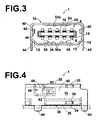
- Figure 3 is a front view of the receptacle connector of Figure 1.
- Figure 4 is a side view of the receptacle connector of Figure 1.
- Figure 5 is a plan view of the receptacle connector of Figure 1.
- Figure 6 is a bottom view of the receptacle connector of Figure 1.
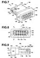
- Figure 7 is a perspective view of a plug connector according to the present invention, from its rear end.
- Figure 8 is a front view of the plug connector of Figure 7.
- Figure 9 is a side view of the plug connector of Figure 7.
- Figure 10 is a sectional view of the plug connector, taken along line X-X in Figure 8.
- Figure 11 is a partial sectional view of the assembly in a state in which the plug connector and the receptacle connector are completely engaged.
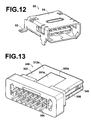
- Figure 12 is a perspective view of a modified receptacle connector.
- Figure 13 is a perspective view of a plug connector, which is a constituent of an electrical connector assembly according to a second embodiment of the present invention.
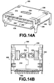
- Figure 14A and Figure 14B show a receptacle connector, which is to be engaged with the plug connector of Figure 13, wherein Figure 14A is a perspective view and Figure 14B is a bottom view.
- Figure 15 is a vertical sectional view of the electrical connector assembly according to the second embodiment, in a state in which the receptacle connector and the plug connector are completely engaged.
- FIG. 1 is a perspective view of a receptacle connector 1, which is the first connector of the assembly C, from its front end 2.
- Figure 2 is a perspective view of the receptacle connector 1 from its rear end 4.
- Figure 3 is a front view
- Figure 4 is a side view
- Figure 5 is a plan view
- Figure 6 is a bottom view of the receptacle connector 1.
- the receptacle connector 1 comprises: an insulative housing 6 (hereinafter, simply referred to as "housing”); contacts 8 (first contacts) , which are held by the housing 6; and a shielding member, that is, a shell 10, which is provided so as to cover the periphery of the housing 6.
- the housing 6 comprises a main body having a substantially rectangular shape when viewed from the front. Tapers 12 are formed at both lower corners of the main body 14. A contact supporting plate 16 protrudes from the front end of the main body 14. A plurality of contact receiving grooves 18 are provided at predetermined intervals in the upper and lower surfaces of the contact supporting plate 16. The contacts 8 are press fit into the contact receiving grooves 18 and placed therein. Each of the contacts 8 comprises: a tine 22 that extends toward the rear of the main body 14 to be connected to a circuit board 26 (refer to Figure 4); and a contacting portion 24 for contacting second contacts 104 (refer to Figure 7), which will be described later.
- the shell 10 is formed by punching and bending a single conductive metal plate so as to be of a shape that surrounds the periphery of the main body 14.
- the ends of the shell 10 abut each other at a seam 60, to house the entirety of the housing 6 therein.
- the seam 60 is formed as a dovetail joint, which causes it to be difficult for the ends of the shell 10 to become separated.
- Tongue pieces 30 are formed at both sides of an upper wall 28 of the shell 10, toward the rear end 4 thereof.
- the tongue pieces 30 are formed by punching, and are of a cantilevered structure having their fixed ends at the upper wall 28.
- the tongue pieces 30 are formed perpendicular to an insertion/extraction direction 62 (refer to Figure 1) , and are bent inwardly.
- Recesses 32 are formed in the main body 14 at positions corresponding to the tongue pieces, and the tongue pieces 30 engage the interiors of the recesses 32.
- Tongue pieces 34 which are similar to the tongue pieces 30, are formed at a bottom wall 36 of the shell 10, and engage recesses 38, which are formed in the lower portion of the main body 14.
- the shell 10 is fixed to the housing by the engagement of the tongue pieces 30 and 34 with the recesses 32 and 38.
- L-shaped spring pieces 46 are formed by punching out the upper wall 28 and the side walls 40 in the vicinity of the front end 2 of the shell 10.
- the spring pieces 46 have their fixed ends at the upper wall 28, and are formed symmetrically on the right and left side walls 40 of the shell 10.
- Each of the spring pieces 46 comprises: an arm 48 that extends from the upper wall 28 through the side wall 40; and an engaging piece 50 that extends rearward from the tip of the arm 48, perpendicular thereto.
- An engaging protrusion 52 (locking portion) that protrudes inwardly in an arcuate manner is formed on each engaging piece 50.
- the rear portions of the engaging protrusions 52 function as engaging surfaces 52a (refer to Figure 11) .
- the engaging protrusions 52 are arcuate in shape, and that they do not have engaging surfaces which are perpendicular to the insertion/extraction direction 62. For this reason, an engagement holding force becomes comparatively low, when the receptacle connector 1 is engaged with a plug connector 100 (refer to Figure 7), which will be described later.
- press contacting protrusions 54 and 56 (beads), which are characteristic features of the present invention, will be described.
- the press contacting protrusions 54 and 56 are formed on the upper wall 28 and the lower wall 36 of the shell 10, by inwardly punching the upper wall 28 and the lower wall 36.
- the press contacting protrusions 54 and 56 protrude slightly from the upper wall 28 and the lower wall 36 toward the interior of the shell 10, respectively.
- the dimensions of the press contacting protrusions 54 and 56 are such that they slidingly contact an insulative housing 102 of the plug connector 100 (refer to Figure 7) when the plug connector 100 and the receptacle connector 1 are engaged with each other.
- the two press contacting protrusions 56 on the bottom wall 36 are substantially ellipsoid in shape, and are provided on both sides of the seam 60.
- the press contacting protrusions 54 and 56 have longitudinal axes 58 and 59, respectively.
- the longitudinal axes 58 and 59 are perpendicular to the insertion/extraction direction 62 of the connectors.
- the press contacting protrusions 54, 56, and 56 are formed at positions that face each other, to balance the force which is exerted on the insulative housing 102 in the vertical direction.
- the longitudinal axes 58 and 59 are perpendicular to the insertion/extraction direction 62.
- the upper surface 112a and the lower surface 112b of the insulative housing 102 are likely to be marred.
- contact portions 54a and 56a (refer to Figure 3) of the press contacting protrusions 54 and 56 are linear and parallel to the insertion/extraction direction 62
- the upper surface 112a and the lower surface 112b of the insulative housing 102 become scored, causing linear marks to be formed thereon. This decreases the engagement holding force, and also deteriorates the outward appearance of the plug connector 100. Further, shavings from the scoring may become attached to the contacts 8 and contacts 104 (refer to Figure 7), thereby adversely affecting the contact properties therebetween.
- FIG. 7 is a perspective view of the plug connector 100 from its rear end.
- Figure 8 is a front view
- Figure 9 is a side view
- Figure 10 is a sectional view taken along line X-X in Figure 8, of the plug connector.
- Figure 11 is a partial sectional view of the assembly C in a state in which the plug connector 100 and the receptacle connector 1 are completely engaged.
- the plug connector 100 comprises: a plastic insulative housing 102 (hereinafter, simply referred to as "housing"); contacts 104 (second contacts), which are held by the housing 102; and locking pieces 106, which are mounted on both sides of the housing 102.
- the housing 102 comprises a main body 108, which is shaped as a rectangular block, and an engaging portion 112, which protrudes toward the front via a step 110.
- Contact apertures 114 are formed in the housing 102, at positions corresponding to those of apertures 20 of the receptacle connector 1.
- the contact apertures 114 are provided as two rows, which are separated in the vertical direction.
- the contact apertures 114 penetrate through the housing 102 of the plug connector 100 in a direction parallel to the insertion/extraction direction 62.
- the contacts 104 are press fit within the contact apertures 114 from the rear ends thereof.
- each of the contacts 104 comprises: a tine 116 for connecting to a wire (not shown) or a circuit board; a press fit portion 120, which has barbs 118 at both lateral edges thereof; and a contact portion 122 for contacting the contact 8.
- the contacts 104 are press fitted into the hosing 102, the barbs 118 frictionally engage with the housing 102, thereby fixing the contacts 104 to the housing 102.
- Apertures 124, for the locking pieces 106 to penetrate, are formed at both sides of the rows of contacts in the main body 108 of the housing 102.
- Locking piece receiving grooves 126 that communicate with the apertures 124 are formed at both sides of the engaging portion 112, parallel to the insertion/extraction direction 62.
- the locking piece receiving grooves 126 extend to the vicinity of an engagement surface 128. In other words, the tips 106a of the locking pieces 106, which are held within the locking piece receiving grooves 126, are not exposed at the engagement surface 128.
- the locking piece receiving grooves 126 are of widths that are capable of receiving the lateral edges 106b of the locking pieces 106 therein.
- the locking pieces 106 are held by the housing 102 so that neither the tips 106a nor the lateral edges 106b thereof are exposed to the exterior. Therefore, fingers and the like are prevented from contacting the edges of the locking pieces, thereby securing safety. That is, electrical connection requirements can be satisfied while maintaining safety.
- Each of the locking pieces 106 comprises: a pressing portion 132 at its rear end, that abuts the rear surface 130 of the housing 102; and barbs 134 (refer to Figure 10) for engaging the housing 102, formed at the lateral edges of the locking piece 106 in the vicinity of its rear end. Cutouts 138 are formed in both lateral edges 106b at the tip of each of the locking pieces 106. Outwardly protruding engaging protrusions 140 (locking portions) are formed at the cutouts 138. Each engaging protrusion 140 comprises: a forward facing inclined surface 140a; and a rearward facing inclined surface 140b. When the plug connector 100 and the receptacle connector 1 are engaged, the engaging protrusions 140 and the engaging protrusions 52 engage each other. This engagement state will be described with reference to Figure 11.
- the contacts 8 and the contacts 104 contact each other, and are frictionally engaged.
- the spring pieces 46 and the locking pieces 106 are engaged to each other by the engagement between the engaging protrusions 52 and the engagement protrusions 140, that is, their locking portions.
- the spring pieces 46 flex toward the exterior (downward in Figure 11) due to its elasticity.
- the engaging protrusions 52 ride over the engaging protrusions 140, the spring pieces 46 elastically return to engage with the locking pieces 106. Due to this flexure and return, a "click" is generated when complete engagement is achieved.
- the inclined surfaces 140b of the lock pieces 106 are engaged with the inclined engaging surfaces 52a of the spring pieces 46.
- the spring pieces 46 and the locking pieces 106 are both metallic. Therefore, they are capable of forming a conductive electrical path.
- the shell 10 is grounded to the circuit board 26, thereby forming an integrated shield (electromagnetic shield).
- the press contacting protrusions 54 and 56 of the receptacle connector 1 slidingly contact the flat upper surface 112a and the flat lower surface 112b of the engaging portion 112 of the plug connector 100 when the connectors are engaged. This contact state is maintained after complete engagement. The frictional force of this contact state also operates as engagement holding force between the connectors.
- the engaging protrusions 54 and 56 generate resistance against the excessive force in the extraction direction, by frictionally contacting the housing 102 of the plug connector 100.
- the connectors are designed so that the resistance is not sufficient to prevent extraction.
- the spring pieces 46 and the locking pieces 106 become worn due to metallic abrasion, after a great number of insertions and extractions.
- the press contacting protrusions 54, 56, and 56 simply contact the plug connector 100 in a sliding manner. Therefore, there is little possibility that the press contacting protrusions 54, 56, and 56 will become worn. Accordingly, even if the spring pieces 46 and the locking pieces 106 become worn, an engagement holding force of a predetermined amount or greater can be maintained.
- the possibility that the surface of the hosing 102 of the plug connector 100 will be marred is small, because the press contacting protrusions 54 and 56 have longitudinal axes 58 and 59, which are perpendicular to the insertion/extraction direction 62. In other words, the orientation of the press contacting protrusions 54 and 56 prevent linear marks from being scored into the upper surface 112a and the lower surface 112b of the housing 102.
- the frictional engagement between the contacts 8 and 104 also serves to resist extraction. However, in the case that the number of contacts 8 and 104 is small, the frictional force of the press contacting protrusions 54, 56, and 56 are effective in maintaining a predetermined engagement holding force.
- the receptacle connector 1 and the plug connector 100 are designed to have an engagement holding force great enough to damage either when excessive external force is applied to the plug connector. Therefore, damage to the locking portions of the plug connector 100 and the receptacle connector 1 is prevented.
- a connected device is a lightweight electronic device such as a cellular telephone. If. external force pulls on the connectors and the engagement holding force is too great, the electronic device itself may be pulled off of a table, fall, and be damaged. However, this problem will not occur with the low engagement holding force of the connectors according to the present invention.
- Figure 12 is a perspective view of a modified receptacle connector 80.
- the shape of the mounting legs 42 for mounting the receptacle connector 1 to the circuit board 26 may be modified.
- the receptacle connector 80 differs from the receptacle connector 1 in that the rearward mounting legs 82 of a shell 84 are of the SMT (Surface Mounting Technology) type, as opposed to the dip type. This is because prying forces, which are likely to be exerted on the front portion during insertion and extraction of the connectors, are less likely to be exerted on the rear portion.
- SMT Surface Mounting Technology
- the press contacting protrusion 54 it is preferable for the press contacting protrusion 54 to have the contact portion 54a thereof be linear, in a direction perpendicular to the insertion/extraction direction 62.
- the contact portion 54a may have a desired length in the direction along the insertion/extraction direction 62, in order to obtain an appropriate engagement holding force.
- the engaging protrusions 52 of the spring pieces 46 are arcuate.
- the shape of the engaging protrusions may alternatively be inclines surfaces having comparatively low engagement holding forces.
- Figure 13 is a perspective view of a plug connector 300 (second connector) , which is a constituent of the assembly C' (refer to Figure 15) .
- Figure 14A is a perspective view of a receptacle connector 200 (first connector), which is to be engaged with the plug connector 300.
- Figure 14B is a bottom view of the receptacle connector 200.
- Figure 15 is a vertical sectional view of the assembly C', in a state in which the receptacle connector 200 and the plug connector 300 are completely engaged.
- the plug connector 300 differs from the plug connector 100 in that it has fourteen contacts 304 (second contacts) .
- the plug connector 300 also comprises steps 350a and 350b, for engaging press contacting protrusions 254 and 256 to be described later, of the receptacle connector 200.
- the steps 350a and 350b are formed on the upper surface 312a and the lower surface 312b, respectively, of a housing 302 of the plug connector 300. Note that the steps 350a and 350b will collectively be referred to as steps 350.
- the step 350a is formed on the upper surface 312a at a position corresponding to that of the press contacting protrusion 254 of the receptacle connector 200.
- the step 350a is formed as a rearward extending flat surface 351a, which has a width capable of receiving the width of the press contacting protrusion 254.
- the steps 350b are formed on the lower surface 312b at positions corresponding to those of the press contacting protrusions 256 of the receptacle connector 200.
- the steps 350b are formed as rearward extending flat surfaces 351b, which have widths capable of receiving the widths of the press contacting protrusions 256 (refer to Figure 15).
- the depth of the step 350a is exaggerated in Figure 13 for the sake of clear illustration thereof. However, the actual depths of the steps 350 are approximately 0.1mm.
- the plug connector 300 comprises engaging protrusions 340 (locking portions), which are formed on locking pieces 306. However, they are of the same construction as those of the plug connector 100, so a detailed description thereof will be omitted.
- the receptacle connector 200 to be engaged with the plug connector 300 is of the same basic construction as the receptacle connector 1 of Figure 1, except that fourteen contacts are provided therein, as illustrated in Figure 14. That is, a press contacting protrusion 254, which is similar to the press contacting protrusion 54, is formed on an upper wall 228. In addition, two press contacting protrusions 256, which are similar to the press contacting protrusions 56, are formed on a bottom wall 236. The press contacting protrusions 256 are formed at positions corresponding to those of the steps 350b.
- the receptacle connector 200 comprises: a housing 206; contacts 208 (first contacts); a shell 210; spring pieces 246; and engaging protrusions 252 (locking portions).
- contacts 208 first contacts
- shell 210 shell 210
- spring pieces 246 engaging protrusions 252 (locking portions).
- engaging protrusions 252 locking portions
Landscapes
- Details Of Connecting Devices For Male And Female Coupling (AREA)
- Coupling Device And Connection With Printed Circuit (AREA)
Abstract
Description
- The present invention relates to an electrical connector assembly, to be utilized in electric/electronic devices such as cellular telephones and digital cameras. The present invention also relates to a receptacle connector and a plug connector, to be employed in the electrical connector assembly.
- Electrical connector assemblies having locking mechanisms, for locking connectors to each other, are common. For example, there is known an electrical connector assembly as disclosed in U. S. Patent No. 5, 879, 194 (Figure 8, Figure 9) . This electrical connector assembly comprises a socket .(receptacle connector) which has a metallic shielding member at its exterior, and a plug (plug connector) for engaging with the socket. Locking protrusions comprising hooks are formed on the shield member of the socket. The hooks are configured to engage apertures, which are formed in the plug, during engagement of the socket and the plug. To release the engagement, the locking protrusions are pressed.
- In the electrical connector assembly disclosed in U. S. Patent No. 5,879,194, the engaged state of the socket and plug is maintained by the positive engagement between the hooks and the apertures. However, if an excessive force is applied in the extraction direction of the plug while in the engaged state, the locking protrusions (hooks) and the apertures may be damaged.
- The application of excessive force occurs accidentally during normal use of electric/electronic devices. For example, it is likely for a headphone cord to get caught on something, while listening to music with a Mini Disc player through headphones. Cords for other devices may also get caught on things, such as when listening to music downloaded to a cellular telephone through earphones, recharging a digital camera, and connecting cords in general. As a result, external force is applied to the cord, which then leads to an excessive extraction force being exerted on connectors. This leads to the possibility of damaging the locking portions of the connectors, or of dropping and damaging the device itself. For this reason, connectors of this type, so-called multimedia interface connectors, are manufactured with predetermined design standards that assume that excessive external force will be applied thereto.
- Specifically, connectors are designed to have engagement holding forces within a predetermined range (5N to 10N, for example). In the case that an external force, that is, an extraction force, over a certain load is applied, the connectors are to separate without damage thereto. It is desired that connectors are designed to withstand 10, 000 cycles of a continuous insertion/extraction test, so that the above function is not lost during the product lifetime thereof.
- The present invention has been developed in view of the above circumstances. It is an object of the present invention to provide an electrical connector assembly, a receptacle connector, and a plug connector that maintain a comparatively low engagement holding force over an extremely large number of insertions and extractions, thereby releasing the engagement (lock) between the connectors in the case that external force is applied.
- It is another object of the present invention to provide an electrical connector assembly, a receptacle connector, and a plug connector in which marring of the connectors' surfaces due to the insertion and extraction thereof is avoided.
- The electrical connector assembly of the present invention comprises:
- a first connector having a first insulative housing for holding at least one first contact; and
- a second connector having a second insulative housing for
holding second contacts that contact the first contact during
engagement with the first connector; wherein:
- the first and second connectors comprise locking portions for locking with each other during engagement with a low engagement holding force; and
- protrusions for frictionally contacting the second connector are provided on the first connector.
-
- A configuration may be adopted wherein the electrical connector assembly further comprises:
- a metallic shell for containing the second insulative
housing, provided at the exterior of the first insulative housing;
and wherein:
- the locking portions comprise spring pieces, which are formed on the metallic shell, and metallic locking pieces, which are provided on the second insulative housing.
-
- It is preferable that the metallic locking pieces are provided at the two sides of the second insulative housing, and that the tips of the locking pieces are protected by the front end of the second insulative housing.
- A configuration may also be adopted wherein the protrusions protrude from the metallic shell toward the surface of the second insulative housing, during engagement of the first and second connectors.
- It is preferable that the longitudinal axes of the protrusions are perpendicular to the engagement/disengagement direction of the first and second connectors. In addition, it is preferable that the protrusions are provided at the top and the bottom of the metallic shell.
- Further, a configuration may be adopted wherein steps, for the protrusions to engage with during engagement of the first and second connectors, are formed on the surface of the second connector at positions corresponding to the protrusions of the first connector.
- The receptacle connector of the present invention is a receptacle connector for engaging a plug connector, comprising:
- an insulative housing; and
- at least one contact held within the insulative housing;
wherein:
- a metallic shell is provided toward the exterior of the insulative housing;
- locking portions comprising spring pieces, for locking with locking portions of the plug connector during engagement therewith, is formed on the metallic shell; and
- protrusions for frictionally contacting the surface of an insulative housing of the plug connector, which is inserted into the interior of the metallic shell, are provided on the metallic shell.
-
- The plug connector of the present invention is a plug connector for engaging a receptacle connector, comprising:
- an insulative housing; and
- at least one contact held in the insulative housing;
wherein:
- locking portions comprising metallic locking pieces, for locking with locking portions of the receptacle connector with a low engagement holding force during engagement therewith, are provided at the exterior of the insulative housing; and
- a configuration is adopted so that protrusions of the receptacle connector frictionally contact the insulative housing, when the plug connector is inserted into the receptacle connector.
-
- A configuration may be adopted wherein:
- steps are formed on the surface of the insulative housing of the plug connector, at positions corresponding to the protrusions of the receptacle connector.
-
- Both the first and the second connectors of the electrical connector assembly of the present invention comprise locking portions, which are locked to each other with a low engagement holding force during engagement of the connectors. In addition, protrusions for frictionally contacting the second connector are provided on the first connector. Therefore, the following advantageous effects are exhibited.
- Even if the locking portions become worn, a comparatively low engagement holding force can be maintained between the connectors over an extremely large number of insertions and extractions, by the engagement holding force due to the friction with the protrusions.
- A configuration may be adopted wherein a metallic shell for containing the second insulative housing is provided at the exterior of the first insulative housing; and wherein: the locking portions comprise spring pieces, which are formed on the metallic shell, and metallic locking pieces, which are provided on the second insulative housing. In this case, a conductive path can be formed via the locking portions, and an integrated shield (electromagnetic shield) for the connector assembly can be formed.
- In the case that the protrusions protrude from the metallic shell toward the surface of the second insulative housing of the second connector, formation of the protrusions is facilitated.
- In the case that the longitudinal axes of the protrusions is perpendicular to the engagement/disengagement direction of the first and second connectors, marring is less likely to occur on the surface of the second connector during insertion and extraction thereof.
- A construction may be adopted wherein steps, for the protrusions to engage with during engagement of the first and second connectors, are formed on the surface of the second connector at positions corresponding to the protrusions of the first connector. In this case, a "click" is generated by the engagement of the protrusions and the steps when the connectors are completely engaged with each other. This "click", combined with the "click" generated by the engagement of the locking portions, increases the "click" perceived by a user. Therefore, complete engagement can be positively perceived through the sense of touch of the user's hands (fingers). Further, the engagement holding force can be increased by the engagement of the protrusions with the steps.
- The receptacle connector of the present invention comprises an insulative housing;
- a metallic shell provided toward the exterior of the insulative housing;
- locking portions comprising spring pieces, for locking with locking portions of a plug connector during engagement therewith, formed on the metallic shell; and
- protrusions for frictionally contacting the surface of an insulative housing of the plug connector, which is inserted intc the interior of the metallic shell, provided on the metallic shell By this construction, the receptacle connector is capable of maintaining a comparably low engagement holding force with the plug connector over an extremely large number of insertions and extractions.
-
- The plug connector of the present invention comprises:
- locking portions comprising metallic locking pieces, for locking with locking portions of the receptacle connector with a low engagement holding force during engagement therewith, are provided at the exterior of the insulative housing; and
- a configuration is adopted so that protrusions of the receptacle connector frictionally contact the insulative housing, when the plug connector is inserted into the receptacle connector. By this construction, the plug connector is capable of maintaining a comparably low engagement holding force with the receptacle connector over an extremely large number of insertions and extractions. In addition, this construction enables a conductive path to be formed with the receptacle connector, via the locking portions.
-
- Figure 1 is a perspective view of a receptacle connector, which is the first connector of an electrical connector assembly according to the present invention, from its front end.
- Figure 2 is a perspective view of the receptacle connector of
Fiqure 1, from its rear end. - Figure 3 is a front view of the receptacle connector of Figure 1.
- Figure 4 is a side view of the receptacle connector of Figure 1.
- Figure 5 is a plan view of the receptacle connector of Figure 1.
- Figure 6 is a bottom view of the receptacle connector of Figure 1.
- Figure 7 is a perspective view of a plug connector according to the present invention, from its rear end.
- Figure 8 is a front view of the plug connector of Figure 7.
- Figure 9 is a side view of the plug connector of Figure 7.
- Figure 10 is a sectional view of the plug connector, taken along line X-X in Figure 8.
- Figure 11 is a partial sectional view of the assembly in a state in which the plug connector and the receptacle connector are completely engaged.
- Figure 12 is a perspective view of a modified receptacle connector.
- Figure 13 is a perspective view of a plug connector, which is a constituent of an electrical connector assembly according to a second embodiment of the present invention.
- Figure 14A and Figure 14B show a receptacle connector, which is to be engaged with the plug connector of Figure 13, wherein Figure 14A is a perspective view and Figure 14B is a bottom view.
- Figure 15 is a vertical sectional view of the electrical connector assembly according to the second embodiment, in a state in which the receptacle connector and the plug connector are completely engaged.
- Hereinafter, preferred embodiments of an electrical connector assembly C (hereinafter, simply referred to as "assembly"), the receptacle connector, and the plug connector will be described with reference to the attached drawings. Figure 1 is a perspective view of a
receptacle connector 1, which is the first connector of the assembly C, from itsfront end 2. Figure 2 is a perspective view of thereceptacle connector 1 from itsrear end 4. Figure 3 is a front view, Figure 4 is a side view, Figure 5 is a plan view, and Figure 6 is a bottom view of thereceptacle connector 1. Hereinafter, a description will be given with reference to Figure 1 through Figure 6. - The
receptacle connector 1 comprises: an insulative housing 6 (hereinafter, simply referred to as "housing"); contacts 8 (first contacts) , which are held by thehousing 6; and a shielding member, that is, ashell 10, which is provided so as to cover the periphery of thehousing 6. - As most clearly illustrated in Figure 3, the
housing 6 comprises a main body having a substantially rectangular shape when viewed from the front.Tapers 12 are formed at both lower corners of themain body 14. Acontact supporting plate 16 protrudes from the front end of themain body 14. A plurality ofcontact receiving grooves 18 are provided at predetermined intervals in the upper and lower surfaces of thecontact supporting plate 16. Thecontacts 8 are press fit into thecontact receiving grooves 18 and placed therein. Each of thecontacts 8 comprises: atine 22 that extends toward the rear of themain body 14 to be connected to a circuit board 26 (refer to Figure 4); and a contactingportion 24 for contacting second contacts 104 (refer to Figure 7), which will be described later. - Next, the
shell 10 will be described. Theshell 10 is formed by punching and bending a single conductive metal plate so as to be of a shape that surrounds the periphery of themain body 14. The ends of theshell 10 abut each other at aseam 60, to house the entirety of thehousing 6 therein. Theseam 60 is formed as a dovetail joint, which causes it to be difficult for the ends of theshell 10 to become separated.Tongue pieces 30 are formed at both sides of anupper wall 28 of theshell 10, toward therear end 4 thereof. Thetongue pieces 30 are formed by punching, and are of a cantilevered structure having their fixed ends at theupper wall 28. Thetongue pieces 30 are formed perpendicular to an insertion/extraction direction 62 (refer to Figure 1) , and are bent inwardly.Recesses 32 are formed in themain body 14 at positions corresponding to the tongue pieces, and thetongue pieces 30 engage the interiors of therecesses 32.Tongue pieces 34, which are similar to thetongue pieces 30, are formed at abottom wall 36 of theshell 10, and engagerecesses 38, which are formed in the lower portion of themain body 14. Theshell 10 is fixed to the housing by the engagement of thetongue pieces recesses - Downwardly extending mounting
legs shell 10 at the front and rear of bothside walls 40 thereof. The mountinglegs circuit board 26. L-shapedspring pieces 46 are formed by punching out theupper wall 28 and theside walls 40 in the vicinity of thefront end 2 of theshell 10. Thespring pieces 46 have their fixed ends at theupper wall 28, and are formed symmetrically on the right and leftside walls 40 of theshell 10. Each of thespring pieces 46 comprises: anarm 48 that extends from theupper wall 28 through theside wall 40; and an engagingpiece 50 that extends rearward from the tip of thearm 48, perpendicular thereto. An engaging protrusion 52 (locking portion) that protrudes inwardly in an arcuate manner is formed on each engagingpiece 50. The rear portions of the engagingprotrusions 52 function as engagingsurfaces 52a (refer to Figure 11) . Here, it is important to note that the engagingprotrusions 52 are arcuate in shape, and that they do not have engaging surfaces which are perpendicular to the insertion/extraction direction 62. For this reason, an engagement holding force becomes comparatively low, when thereceptacle connector 1 is engaged with a plug connector 100 (refer to Figure 7), which will be described later. - Next,
press contacting protrusions 54 and 56 (beads), which are characteristic features of the present invention, will be described. Thepress contacting protrusions upper wall 28 and thelower wall 36 of theshell 10, by inwardly punching theupper wall 28 and thelower wall 36. Thepress contacting protrusions upper wall 28 and thelower wall 36 toward the interior of theshell 10, respectively. The dimensions of thepress contacting protrusions insulative housing 102 of the plug connector 100 (refer to Figure 7) when theplug connector 100 and thereceptacle connector 1 are engaged with each other. The twopress contacting protrusions 56 on thebottom wall 36 are substantially ellipsoid in shape, and are provided on both sides of theseam 60. Thepress contacting protrusions longitudinal axes longitudinal axes extraction direction 62 of the connectors. Thepress contacting protrusions insulative housing 102 in the vertical direction. - The
longitudinal axes extraction direction 62. In the case that thelongitudinal axes extraction direction 62, theupper surface 112a and thelower surface 112b of theinsulative housing 102 are likely to be marred. Particularly in the case thatcontact portions press contacting protrusions extraction direction 62, theupper surface 112a and thelower surface 112b of theinsulative housing 102 become scored, causing linear marks to be formed thereon. This decreases the engagement holding force, and also deteriorates the outward appearance of theplug connector 100. Further, shavings from the scoring may become attached to thecontacts 8 and contacts 104 (refer to Figure 7), thereby adversely affecting the contact properties therebetween. - Next, the
plug connector 100, which is the second connector, will be described with reference to Figure 7 through Figure 10. Figure 7 is a perspective view of theplug connector 100 from its rear end. Figure 8 is a front view, Figure 9 is a side view, and Figure 10 is a sectional view taken along line X-X in Figure 8, of the plug connector. Figure 11 is a partial sectional view of the assembly C in a state in which theplug connector 100 and thereceptacle connector 1 are completely engaged. Theplug connector 100 comprises: a plastic insulative housing 102 (hereinafter, simply referred to as "housing"); contacts 104 (second contacts), which are held by thehousing 102; and lockingpieces 106, which are mounted on both sides of thehousing 102. Thehousing 102 comprises amain body 108, which is shaped as a rectangular block, and an engagingportion 112, which protrudes toward the front via astep 110. Contactapertures 114 are formed in thehousing 102, at positions corresponding to those ofapertures 20 of thereceptacle connector 1. Thecontact apertures 114 are provided as two rows, which are separated in the vertical direction. Thecontact apertures 114 penetrate through thehousing 102 of theplug connector 100 in a direction parallel to the insertion/extraction direction 62. Thecontacts 104 are press fit within thecontact apertures 114 from the rear ends thereof. As illustrated in Figure 11, each of thecontacts 104 comprises: atine 116 for connecting to a wire (not shown) or a circuit board; a pressfit portion 120, which hasbarbs 118 at both lateral edges thereof; and acontact portion 122 for contacting thecontact 8. When thecontacts 104 are press fitted into the hosing 102, thebarbs 118 frictionally engage with thehousing 102, thereby fixing thecontacts 104 to thehousing 102. -
Apertures 124, for the lockingpieces 106 to penetrate, are formed at both sides of the rows of contacts in themain body 108 of thehousing 102. Lockingpiece receiving grooves 126 that communicate with theapertures 124 are formed at both sides of the engagingportion 112, parallel to the insertion/extraction direction 62. The lockingpiece receiving grooves 126 extend to the vicinity of anengagement surface 128. In other words, thetips 106a of the lockingpieces 106, which are held within the lockingpiece receiving grooves 126, are not exposed at theengagement surface 128. The lockingpiece receiving grooves 126 are of widths that are capable of receiving thelateral edges 106b of the lockingpieces 106 therein. As described above, the lockingpieces 106 are held by thehousing 102 so that neither thetips 106a nor thelateral edges 106b thereof are exposed to the exterior. Therefore, fingers and the like are prevented from contacting the edges of the locking pieces, thereby securing safety. That is, electrical connection requirements can be satisfied while maintaining safety. - Each of the locking
pieces 106 comprises: apressing portion 132 at its rear end, that abuts therear surface 130 of thehousing 102; and barbs 134 (refer to Figure 10) for engaging thehousing 102, formed at the lateral edges of thelocking piece 106 in the vicinity of its rear end.Cutouts 138 are formed in bothlateral edges 106b at the tip of each of the lockingpieces 106. Outwardly protruding engaging protrusions 140 (locking portions) are formed at thecutouts 138. Each engagingprotrusion 140 comprises: a forward facinginclined surface 140a; and a rearward facinginclined surface 140b. When theplug connector 100 and thereceptacle connector 1 are engaged, the engagingprotrusions 140 and the engagingprotrusions 52 engage each other. This engagement state will be described with reference to Figure 11. - As clearly illustrated in Figure 11, the
contacts 8 and thecontacts 104 contact each other, and are frictionally engaged. In addition, thespring pieces 46 and the lockingpieces 106 are engaged to each other by the engagement between the engagingprotrusions 52 and theengagement protrusions 140, that is, their locking portions. Immediately prior to complete engagement, thespring pieces 46 flex toward the exterior (downward in Figure 11) due to its elasticity. When the engagingprotrusions 52 ride over the engagingprotrusions 140, thespring pieces 46 elastically return to engage with the lockingpieces 106. Due to this flexure and return, a "click" is generated when complete engagement is achieved. In this engaged state, theinclined surfaces 140b of thelock pieces 106 are engaged with the inclined engagingsurfaces 52a of thespring pieces 46. Thespring pieces 46 and the lockingpieces 106 are both metallic. Therefore, they are capable of forming a conductive electrical path. In the present invention, theshell 10 is grounded to thecircuit board 26, thereby forming an integrated shield (electromagnetic shield). - In addition, the
press contacting protrusions receptacle connector 1 slidingly contact the flatupper surface 112a and the flatlower surface 112b of the engagingportion 112 of theplug connector 100 when the connectors are engaged. This contact state is maintained after complete engagement. The frictional force of this contact state also operates as engagement holding force between the connectors. - If excessive force is exerted on the
plug connector 100 in the extraction direction indicated byarrow 142 while in the engaged state, a force is applied on theinclined surfaces 140b that attempts to move them in the direction ofarrow 142. This force works to cause theinclined surfaces 140b to flex the engagingsurfaces 52a outward. When this force exceeds the engagement holding force of the engagingprotrusions 52 and the engagingprotrusions 140, thespring pieces 46 are flexed outward to release the engagement, and theplug connector 100 is extracted. - At this time, the engaging
protrusions housing 102 of theplug connector 100. However, the connectors are designed so that the resistance is not sufficient to prevent extraction. Thespring pieces 46 and the lockingpieces 106 become worn due to metallic abrasion, after a great number of insertions and extractions. However, thepress contacting protrusions plug connector 100 in a sliding manner. Therefore, there is little possibility that thepress contacting protrusions spring pieces 46 and the lockingpieces 106 become worn, an engagement holding force of a predetermined amount or greater can be maintained. Further, the possibility that the surface of the hosing 102 of theplug connector 100 will be marred is small, because thepress contacting protrusions longitudinal axes extraction direction 62. In other words, the orientation of thepress contacting protrusions upper surface 112a and thelower surface 112b of thehousing 102. In addition, the frictional engagement between thecontacts contacts press contacting protrusions - As described above, the
receptacle connector 1 and theplug connector 100 are designed to have an engagement holding force great enough to damage either when excessive external force is applied to the plug connector. Therefore, damage to the locking portions of theplug connector 100 and thereceptacle connector 1 is prevented. Consider a case in which a connected device is a lightweight electronic device such as a cellular telephone. If. external force pulls on the connectors and the engagement holding force is too great, the electronic device itself may be pulled off of a table, fall, and be damaged. However, this problem will not occur with the low engagement holding force of the connectors according to the present invention. - A preferred embodiment of the present invention has been described above. However, the present invention is not limited to the above embodiment. It goes without saying that various changes and modifications are capable for those skilled in the art.
- For example, Figure 12 is a perspective view of a modified
receptacle connector 80. As illustrated in Figure 12, the shape of the mountinglegs 42 for mounting thereceptacle connector 1 to thecircuit board 26 may be modified. Thereceptacle connector 80 differs from thereceptacle connector 1 in that the rearward mountinglegs 82 of ashell 84 are of the SMT (Surface Mounting Technology) type, as opposed to the dip type. This is because prying forces, which are likely to be exerted on the front portion during insertion and extraction of the connectors, are less likely to be exerted on the rear portion. - It is preferable for the
press contacting protrusion 54 to have thecontact portion 54a thereof be linear, in a direction perpendicular to the insertion/extraction direction 62. However, thecontact portion 54a may have a desired length in the direction along the insertion/extraction direction 62, in order to obtain an appropriate engagement holding force. - The engaging
protrusions 52 of thespring pieces 46 are arcuate. However, the shape of the engaging protrusions may alternatively be inclines surfaces having comparatively low engagement holding forces. - Next, an assembly C' , which has a greater number of contacts than the aforementioned assembly C, will be described with reference to Figure 13 through Figure 15. Figure 13 is a perspective view of a plug connector 300 (second connector) , which is a constituent of the assembly C' (refer to Figure 15) . Figure 14A is a perspective view of a receptacle connector 200 (first connector), which is to be engaged with the
plug connector 300. Figure 14B is a bottom view of thereceptacle connector 200. Figure 15 is a vertical sectional view of the assembly C', in a state in which thereceptacle connector 200 and theplug connector 300 are completely engaged. - As illustrated in Figure 13, the
plug connector 300 differs from theplug connector 100 in that it has fourteen contacts 304 (second contacts) . Theplug connector 300 also comprisessteps press contacting protrusions receptacle connector 200. Thesteps upper surface 312a and thelower surface 312b, respectively, of ahousing 302 of theplug connector 300. Note that thesteps step 350a is formed on theupper surface 312a at a position corresponding to that of thepress contacting protrusion 254 of thereceptacle connector 200. Thestep 350a is formed as a rearward extendingflat surface 351a, which has a width capable of receiving the width of thepress contacting protrusion 254. Thesteps 350b are formed on thelower surface 312b at positions corresponding to those of thepress contacting protrusions 256 of thereceptacle connector 200. Thesteps 350b are formed as rearward extendingflat surfaces 351b, which have widths capable of receiving the widths of the press contacting protrusions 256 (refer to Figure 15). The depth of thestep 350a is exaggerated in Figure 13 for the sake of clear illustration thereof. However, the actual depths of the steps 350 are approximately 0.1mm. - The
plug connector 300 comprises engaging protrusions 340 (locking portions), which are formed on lockingpieces 306. However, they are of the same construction as those of theplug connector 100, so a detailed description thereof will be omitted. - Meanwhile, the
receptacle connector 200 to be engaged with theplug connector 300 is of the same basic construction as thereceptacle connector 1 of Figure 1, except that fourteen contacts are provided therein, as illustrated in Figure 14. That is, apress contacting protrusion 254, which is similar to thepress contacting protrusion 54, is formed on anupper wall 228. In addition, twopress contacting protrusions 256, which are similar to thepress contacting protrusions 56, are formed on abottom wall 236. Thepress contacting protrusions 256 are formed at positions corresponding to those of thesteps 350b. Thereceptacle connector 200 comprises: ahousing 206; contacts 208 (first contacts); ashell 210;spring pieces 246; and engaging protrusions 252 (locking portions). However, as these parts are of the same construction as those of thereceptacle connector 1, detailed descriptions thereof will be omitted. - When the
plug connector 300 and thereceptacle connector 200 are engaged, thepress contacting protrusions portions
Claims (8)
- An electrical connector assembly (c) comprising:a first connector (1) having a first insulative housing (6) for holding at least one first contact (8); anda second connector (100) having a second insulative housing (102) for holding second contacts (104) that contact the first contact (8) during engagement with the first connector (1); wherein:the first and second connectors (1,100) comprise locking portions (52,140) for locking with each other during engagement with a low engagement holding force; andprotrusions (54,56) provided on the first connector (1) for frictionally contacting the second connector (100).
- An electrical connector assembly (c) as defined in claim 1, further comprising:a metallic shell (10) for containing the second insulative housing (102), provided at the exterior of the first insulative housing (6); and wherein:the locking portions comprise spring pieces (52), which are formed on the metallic locking pieces (106), which are provided on the second insulative housing (102).
- An electrical connector assembly (c) as defined in claim 2, wherein:the protrusions (54,56) protrude from the metallic shell (10) towards a surface (112a,112b) of the second insulative housing (102), during engagement of the first and second connectors (1,100).
- An electrical connector assembly (c) as defined in claim 1 or claim 3, wherein:longitudinal axes (58,59) of the protrusions (54,56) are perpendicular to an engagement/disengagement direction (62) of the first and second connectors (1,100).
- An electrical connector assembly (c') as defined in any one of claims 1 through 4, wherein:steps (350a,350b), for the protrusions (254,256) to engage with during engagement of the first and second connectors (200,300), are formed on a surface of the second connector (300) at positions corresponding to the protrusions (254,256) of the first connector (200).
- A receptacle connector (1) for engaging a plug connector (100), comprising:an insulative housing (6); andat least one contact (8) held within the insulative housing (6); wherein:a metallic shell (10) is provided toward an exterior of the insulative housing (6);locking portions (52) comprising spring pieces are formed on the metallic shell (10), for locking with locking portions (140) of the plug connector (100) during engagement therewith; andprotrusions (54,56) are provided on the metallic shell (10) for frictionally contacting a surface (112a,112b) of an insulative housing (102) of the plug connector (100), which is inserted into an interior of the metallic shell (10).
- A plug connector (100) for engaging a receptacle connector (1), comprising:an insulative housing (102); andat least one contact (104) held in the insulative housing (102); wherein:locking portions comprising metallic locking pieces (106) are provided at an exterior of the insulative housing (102) for locking with locking portions (52) of the receptacle connector (1) with a low engagement holding force during engagement therewith; anda configuration is adopted so that protrusions (54,56) of the receptacle connector (1) frictionally contact the insulative housing (102) when the plug connector (100) is inserted into the receptacle connector (1).
- A plug connector (300) as defined in claim 7, wherein:steps (350a,350b) are formed on a surface of the insulative housing (302), at positions corresponding to the protrusions (254,256) of the receptacle connector (200).
Applications Claiming Priority (4)
| Application Number | Priority Date | Filing Date | Title |
|---|---|---|---|
| JP2003150464 | 2003-05-28 | ||
| JP2003150464 | 2003-05-28 | ||
| JP2003294137A JP4068029B2 (en) | 2003-05-28 | 2003-08-18 | Electrical connector assembly, receptacle connector and plug connector |
| JP2003294137 | 2003-08-18 |
Publications (2)
| Publication Number | Publication Date |
|---|---|
| EP1482601A1 true EP1482601A1 (en) | 2004-12-01 |
| EP1482601B1 EP1482601B1 (en) | 2011-12-14 |
Family
ID=33134367
Family Applications (1)
| Application Number | Title | Priority Date | Filing Date |
|---|---|---|---|
| EP04253099A Expired - Lifetime EP1482601B1 (en) | 2003-05-28 | 2004-05-26 | Electrical connector assembly |
Country Status (6)
| Country | Link |
|---|---|
| US (1) | US20040242070A1 (en) |
| EP (1) | EP1482601B1 (en) |
| JP (1) | JP4068029B2 (en) |
| KR (1) | KR101078901B1 (en) |
| CN (1) | CN1574494B (en) |
| TW (1) | TWM255549U (en) |
Cited By (3)
| Publication number | Priority date | Publication date | Assignee | Title |
|---|---|---|---|---|
| WO2006074348A1 (en) * | 2005-01-07 | 2006-07-13 | Apple Inc. | Universal serial bus connector and socket coupling arrangements |
| US7540754B2 (en) | 2006-01-06 | 2009-06-02 | Apple Inc. | Universal Serial Bus plug and socket coupling arrangements |
| EP3996213A4 (en) * | 2019-07-24 | 2022-08-03 | Huawei Technologies Co., Ltd. | SHIELDING SHEET, FEMALE CONNECTOR, CONNECTOR ASSEMBLY AND COMMUNICATION DEVICE |
Families Citing this family (21)
| Publication number | Priority date | Publication date | Assignee | Title |
|---|---|---|---|---|
| USD533841S1 (en) * | 2004-10-12 | 2006-12-19 | Advanced-Connectek, Inc. | Connector shell |
| USD521456S1 (en) * | 2004-11-16 | 2006-05-23 | Pent Technologies, Inc. | Female plug configuration |
| US7217146B2 (en) * | 2004-12-17 | 2007-05-15 | Scientific-Atlanta, Inc. | Connector insert for preventing contamination |
| TWM271288U (en) * | 2005-01-07 | 2005-07-21 | Advanced Connectek Inc | Improved shell for an electrical connector |
| TWI276256B (en) * | 2005-05-23 | 2007-03-11 | P Two Ind Inc | Electric connector with reinforced clamping performance |
| JP4544065B2 (en) * | 2005-07-13 | 2010-09-15 | 住友電装株式会社 | connector |
| JP4493590B2 (en) | 2005-12-20 | 2010-06-30 | ヒロセ電機株式会社 | connector |
| US7303432B1 (en) * | 2006-10-17 | 2007-12-04 | Hong Fu Jin Precision Industry (Shenzhen) Co., Ltd. | Mounting apparatus for input/output ports |
| CN102217148A (en) * | 2008-10-22 | 2011-10-12 | Fci公司 | Shielded connector |
| CN102971920A (en) * | 2010-04-12 | 2013-03-13 | Fci连接器新加坡有限公司 | Miniature receptacle electrical connector |
| JP5698094B2 (en) * | 2011-08-31 | 2015-04-08 | 富士通テン株式会社 | connector |
| CN102570139B (en) * | 2012-02-08 | 2014-07-02 | 永泰电子(东莞)有限公司 | Inserted male socket and female socket for electrical connector |
| WO2014091563A1 (en) * | 2012-12-11 | 2014-06-19 | トリニティ株式会社 | Connector connection/release device for portable electronic apparatus |
| US9660389B2 (en) * | 2014-05-26 | 2017-05-23 | Apple Inc. | Additional ground paths for connectors having reduced pin counts |
| DE102015102662A1 (en) * | 2015-02-25 | 2016-08-25 | Harting Electric Gmbh & Co. Kg | Locking for plug contacts |
| US9356405B1 (en) * | 2015-03-05 | 2016-05-31 | Sony Corporation | Connector tongue element for an electrical connector plug receptacle and a method for producing the same |
| DE202015003001U1 (en) | 2015-04-23 | 2015-06-25 | Rosenberger Hochfrequenztechnik Gmbh & Co. Kg | Plug system with low-wear contact |
| CN105680247B (en) * | 2016-01-09 | 2020-07-28 | 富士康(昆山)电脑接插件有限公司 | Electrical connector assembly |
| WO2017146540A1 (en) * | 2016-02-25 | 2017-08-31 | 엘에스엠트론 주식회사 | Receptacle connector |
| KR102575671B1 (en) * | 2018-01-19 | 2023-09-07 | 삼성전자주식회사 | Connector and electronic device inlcuding the same |
| TWM598546U (en) * | 2020-03-18 | 2020-07-11 | 連展科技股份有限公司 | Electrical connector |
Citations (2)
| Publication number | Priority date | Publication date | Assignee | Title |
|---|---|---|---|---|
| EP0738029A1 (en) * | 1995-03-31 | 1996-10-16 | Molex Incorporated | Lockable electrical connector |
| US6364700B1 (en) * | 2000-06-03 | 2002-04-02 | Hon Hai Precision Ind. Co., Ltd. | Electrical connector assembly |
Family Cites Families (17)
| Publication number | Priority date | Publication date | Assignee | Title |
|---|---|---|---|---|
| US5104329A (en) * | 1990-09-21 | 1992-04-14 | Amp Incorporated | Electrical connector assembly |
| US5383794A (en) * | 1993-07-16 | 1995-01-24 | The Whitaker Corporation | Latch actuator for a connector |
| US5586893A (en) * | 1995-07-17 | 1996-12-24 | Itt Corporation | IC card connector shield grounding |
| US5766043A (en) * | 1996-02-29 | 1998-06-16 | Corcom, Inc. | Telephone connector |
| FR2747518B1 (en) * | 1996-04-12 | 1998-06-05 | Framatome Connectors France | SHIELDED CONNECTOR OF THE TYPE COMPRISING A PLUG AND A BASE AND PROVIDED WITH A LOCKING/UNLOCKING DEVICE |
| TW309184U (en) * | 1996-10-14 | 1997-06-21 | Jang Chuen Rung | Feedback and protection circuit of the backlight device in LCD panel |
| TW368202U (en) * | 1998-03-21 | 1999-08-21 | Hon Hai Prec Ind Co Ltd | High frequency transmission electric connector |
| JP2000223191A (en) * | 1999-01-27 | 2000-08-11 | Mitsumi Electric Co Ltd | Small connector |
| JP2000323233A (en) * | 1999-05-10 | 2000-11-24 | Molex Inc | Connector device |
| US6315608B1 (en) * | 2000-03-31 | 2001-11-13 | Molex Incorporated | Channel isolation shield |
| US6659799B2 (en) * | 2000-10-18 | 2003-12-09 | Advanced Connectek Inc. | Electrical connector |
| US6475033B1 (en) * | 2001-10-10 | 2002-11-05 | Hon Hai Precision Ind. Co., Ltd. | Electrical connector |
| US6447311B1 (en) * | 2001-12-28 | 2002-09-10 | Hon Hai Precision Ind, Co., Ltd. | Electrical connector with grounding means |
| JP2003243093A (en) * | 2002-02-21 | 2003-08-29 | Yazaki Corp | USB connector |
| TW549740U (en) * | 2002-07-26 | 2003-08-21 | Hon Hai Prec Ind Co Ltd | Electrical connector |
| US6702616B1 (en) * | 2003-06-17 | 2004-03-09 | North Star Systems Corp. | Retaining terminal structure of connector |
| USD509192S1 (en) * | 2004-06-15 | 2005-09-06 | Excel Cell Electronic Co., Ltd. | Electrical connector |
-
2003
- 2003-08-18 JP JP2003294137A patent/JP4068029B2/en not_active Expired - Fee Related
-
2004
- 2004-05-25 KR KR1020040037569A patent/KR101078901B1/en not_active Expired - Fee Related
- 2004-05-26 EP EP04253099A patent/EP1482601B1/en not_active Expired - Lifetime
- 2004-05-26 US US10/854,697 patent/US20040242070A1/en not_active Abandoned
- 2004-05-26 TW TW093208250U patent/TWM255549U/en not_active IP Right Cessation
- 2004-05-28 CN CN2004100457742A patent/CN1574494B/en not_active Expired - Fee Related
Patent Citations (2)
| Publication number | Priority date | Publication date | Assignee | Title |
|---|---|---|---|---|
| EP0738029A1 (en) * | 1995-03-31 | 1996-10-16 | Molex Incorporated | Lockable electrical connector |
| US6364700B1 (en) * | 2000-06-03 | 2002-04-02 | Hon Hai Precision Ind. Co., Ltd. | Electrical connector assembly |
Cited By (7)
| Publication number | Priority date | Publication date | Assignee | Title |
|---|---|---|---|---|
| WO2006074348A1 (en) * | 2005-01-07 | 2006-07-13 | Apple Inc. | Universal serial bus connector and socket coupling arrangements |
| US7384295B2 (en) | 2005-01-07 | 2008-06-10 | Apple Inc. | Universal serial bus connector and socket coupling arrangements |
| US7878840B2 (en) | 2005-01-07 | 2011-02-01 | Apple Inc. | Universal serial bus plug and receptacle coupling arrangements |
| CN101091292B (en) * | 2005-01-07 | 2011-11-23 | 苹果公司 | Universal Serial Bus Connector and Socket Connection Structure |
| US7540754B2 (en) | 2006-01-06 | 2009-06-02 | Apple Inc. | Universal Serial Bus plug and socket coupling arrangements |
| EP3996213A4 (en) * | 2019-07-24 | 2022-08-03 | Huawei Technologies Co., Ltd. | SHIELDING SHEET, FEMALE CONNECTOR, CONNECTOR ASSEMBLY AND COMMUNICATION DEVICE |
| US12237622B2 (en) | 2019-07-24 | 2025-02-25 | Huawei Technologies Co., Ltd. | Shielding piece, female connector, connector assembly, and communications device |
Also Published As
| Publication number | Publication date |
|---|---|
| JP2005011791A (en) | 2005-01-13 |
| EP1482601B1 (en) | 2011-12-14 |
| KR20040103322A (en) | 2004-12-08 |
| CN1574494A (en) | 2005-02-02 |
| TWM255549U (en) | 2005-01-11 |
| JP4068029B2 (en) | 2008-03-26 |
| CN1574494B (en) | 2010-09-08 |
| KR101078901B1 (en) | 2011-11-01 |
| US20040242070A1 (en) | 2004-12-02 |
Similar Documents
| Publication | Publication Date | Title |
|---|---|---|
| EP1482601B1 (en) | Electrical connector assembly | |
| US7950936B2 (en) | Electrical connector configured with pivotal cover member | |
| US8251733B2 (en) | Cable connector assembly | |
| US7857650B1 (en) | Electrical connector assembly with latching mechanism | |
| US6234833B1 (en) | Receptacle electrical connector assembly | |
| US6565383B1 (en) | Electrical connector with locking member | |
| US5346405A (en) | Shunted connector assembly and shunt assembly therefor | |
| US7422465B2 (en) | Electrical connector having flexible mating portion | |
| US6485315B1 (en) | Electrical plug connector with spring latch and grounding tabs | |
| US8142217B2 (en) | Electronic apparatus having a cover which synchronously defined as a wall of a modular jack disposed thereof | |
| US7402080B2 (en) | Electrical connector for reliably mounted on a printed circuit board | |
| US7566242B2 (en) | Electrical connector with improved contacts | |
| US20100087074A1 (en) | Electronic card connector with a limiting wall for limiting an electronic card obliquely inserted therein | |
| US7273397B2 (en) | Electrical connector having flexible mating portion | |
| US20070202737A1 (en) | Electrical connector with latching member | |
| JP2008130546A (en) | Electric connector | |
| US8961236B2 (en) | Connector preventing electrostatic discharge | |
| US20150087172A1 (en) | Electrical connector | |
| US20060141843A1 (en) | Hooking mechanism of a connector | |
| US20130337679A1 (en) | Electrical connectors and assembly thereof with improved guiding structures | |
| US8628358B2 (en) | Electrical connector having movable central contact | |
| US7371126B2 (en) | Electrical connector with position means | |
| US6146172A (en) | Electrical connector | |
| US7559792B2 (en) | Connector with easily replacement of a slider | |
| US7077690B2 (en) | Electrical connector with improved slider member |
Legal Events
| Date | Code | Title | Description |
|---|---|---|---|
| PUAI | Public reference made under article 153(3) epc to a published international application that has entered the european phase |
Free format text: ORIGINAL CODE: 0009012 |
|
| AK | Designated contracting states |
Kind code of ref document: A1 Designated state(s): AT BE BG CH CY CZ DE DK EE ES FI FR GB GR HU IE IT LI LU MC NL PL PT RO SE SI SK TR |
|
| AX | Request for extension of the european patent |
Extension state: AL HR LT LV MK |
|
| 17P | Request for examination filed |
Effective date: 20050513 |
|
| AKX | Designation fees paid |
Designated state(s): DE FI SE |
|
| 17Q | First examination report despatched |
Effective date: 20090911 |
|
| RAP1 | Party data changed (applicant data changed or rights of an application transferred) |
Owner name: TYCO ELECTRONICS JAPAN G.K. |
|
| GRAP | Despatch of communication of intention to grant a patent |
Free format text: ORIGINAL CODE: EPIDOSNIGR1 |
|
| GRAS | Grant fee paid |
Free format text: ORIGINAL CODE: EPIDOSNIGR3 |
|
| GRAA | (expected) grant |
Free format text: ORIGINAL CODE: 0009210 |
|
| AK | Designated contracting states |
Kind code of ref document: B1 Designated state(s): DE FI SE |
|
| REG | Reference to a national code |
Ref country code: DE Ref legal event code: R096 Ref document number: 602004035651 Country of ref document: DE Effective date: 20120308 |
|
| PG25 | Lapsed in a contracting state [announced via postgrant information from national office to epo] |
Ref country code: SE Free format text: LAPSE BECAUSE OF FAILURE TO SUBMIT A TRANSLATION OF THE DESCRIPTION OR TO PAY THE FEE WITHIN THE PRESCRIBED TIME-LIMIT Effective date: 20111214 |
|
| PGFP | Annual fee paid to national office [announced via postgrant information from national office to epo] |
Ref country code: DE Payment date: 20120529 Year of fee payment: 9 |
|
| PLBE | No opposition filed within time limit |
Free format text: ORIGINAL CODE: 0009261 |
|
| STAA | Information on the status of an ep patent application or granted ep patent |
Free format text: STATUS: NO OPPOSITION FILED WITHIN TIME LIMIT |
|
| 26N | No opposition filed |
Effective date: 20120917 |
|
| REG | Reference to a national code |
Ref country code: DE Ref legal event code: R097 Ref document number: 602004035651 Country of ref document: DE Effective date: 20120917 |
|
| PG25 | Lapsed in a contracting state [announced via postgrant information from national office to epo] |
Ref country code: FI Free format text: LAPSE BECAUSE OF FAILURE TO SUBMIT A TRANSLATION OF THE DESCRIPTION OR TO PAY THE FEE WITHIN THE PRESCRIBED TIME-LIMIT Effective date: 20111214 |
|
| PG25 | Lapsed in a contracting state [announced via postgrant information from national office to epo] |
Ref country code: DE Free format text: LAPSE BECAUSE OF NON-PAYMENT OF DUE FEES Effective date: 20131203 |
|
| REG | Reference to a national code |
Ref country code: DE Ref legal event code: R119 Ref document number: 602004035651 Country of ref document: DE Effective date: 20131203 |