EP1482568A2 - Thermoelectric energy conversion unit and tunnel-type furnace therewith - Google Patents
Thermoelectric energy conversion unit and tunnel-type furnace therewith Download PDFInfo
- Publication number
- EP1482568A2 EP1482568A2 EP20040012367 EP04012367A EP1482568A2 EP 1482568 A2 EP1482568 A2 EP 1482568A2 EP 20040012367 EP20040012367 EP 20040012367 EP 04012367 A EP04012367 A EP 04012367A EP 1482568 A2 EP1482568 A2 EP 1482568A2
- Authority
- EP
- European Patent Office
- Prior art keywords
- thermoelectric conversion
- inner tube
- tunnel
- heat receiving
- conversion modules
- Prior art date
- Legal status (The legal status is an assumption and is not a legal conclusion. Google has not performed a legal analysis and makes no representation as to the accuracy of the status listed.)
- Withdrawn
Links
Images


Classifications
-
- F—MECHANICAL ENGINEERING; LIGHTING; HEATING; WEAPONS; BLASTING
- F27—FURNACES; KILNS; OVENS; RETORTS
- F27B—FURNACES, KILNS, OVENS, OR RETORTS IN GENERAL; OPEN SINTERING OR LIKE APPARATUS
- F27B9/00—Furnaces through which the charge is moved mechanically, e.g. of tunnel type; Similar furnaces in which the charge moves by gravity
- F27B9/14—Furnaces through which the charge is moved mechanically, e.g. of tunnel type; Similar furnaces in which the charge moves by gravity characterised by the path of the charge during treatment; characterised by the means by which the charge is moved during treatment
- F27B9/20—Furnaces through which the charge is moved mechanically, e.g. of tunnel type; Similar furnaces in which the charge moves by gravity characterised by the path of the charge during treatment; characterised by the means by which the charge is moved during treatment the charge moving in a substantially straight path tunnel furnace
-
- F—MECHANICAL ENGINEERING; LIGHTING; HEATING; WEAPONS; BLASTING
- F27—FURNACES; KILNS; OVENS; RETORTS
- F27B—FURNACES, KILNS, OVENS, OR RETORTS IN GENERAL; OPEN SINTERING OR LIKE APPARATUS
- F27B9/00—Furnaces through which the charge is moved mechanically, e.g. of tunnel type; Similar furnaces in which the charge moves by gravity
- F27B9/02—Furnaces through which the charge is moved mechanically, e.g. of tunnel type; Similar furnaces in which the charge moves by gravity of multiple-track type; of multiple-chamber type; Combinations of furnaces
- F27B9/029—Multicellular type furnaces constructed with add-on modules
-
- F—MECHANICAL ENGINEERING; LIGHTING; HEATING; WEAPONS; BLASTING
- F27—FURNACES; KILNS; OVENS; RETORTS
- F27B—FURNACES, KILNS, OVENS, OR RETORTS IN GENERAL; OPEN SINTERING OR LIKE APPARATUS
- F27B9/00—Furnaces through which the charge is moved mechanically, e.g. of tunnel type; Similar furnaces in which the charge moves by gravity
- F27B9/14—Furnaces through which the charge is moved mechanically, e.g. of tunnel type; Similar furnaces in which the charge moves by gravity characterised by the path of the charge during treatment; characterised by the means by which the charge is moved during treatment
- F27B9/20—Furnaces through which the charge is moved mechanically, e.g. of tunnel type; Similar furnaces in which the charge moves by gravity characterised by the path of the charge during treatment; characterised by the means by which the charge is moved during treatment the charge moving in a substantially straight path tunnel furnace
- F27B9/24—Furnaces through which the charge is moved mechanically, e.g. of tunnel type; Similar furnaces in which the charge moves by gravity characterised by the path of the charge during treatment; characterised by the means by which the charge is moved during treatment the charge moving in a substantially straight path tunnel furnace being carried by a conveyor
- F27B9/243—Endless-strand conveyor
-
- F—MECHANICAL ENGINEERING; LIGHTING; HEATING; WEAPONS; BLASTING
- F27—FURNACES; KILNS; OVENS; RETORTS
- F27B—FURNACES, KILNS, OVENS, OR RETORTS IN GENERAL; OPEN SINTERING OR LIKE APPARATUS
- F27B9/00—Furnaces through which the charge is moved mechanically, e.g. of tunnel type; Similar furnaces in which the charge moves by gravity
- F27B9/30—Details, accessories, or equipment peculiar to furnaces of these types
-
- F—MECHANICAL ENGINEERING; LIGHTING; HEATING; WEAPONS; BLASTING
- F27—FURNACES; KILNS; OVENS; RETORTS
- F27D—DETAILS OR ACCESSORIES OF FURNACES, KILNS, OVENS, OR RETORTS, IN SO FAR AS THEY ARE OF KINDS OCCURRING IN MORE THAN ONE KIND OF FURNACE
- F27D17/00—Arrangements for using waste heat; Arrangements for using, or disposing of, waste gases
- F27D17/004—Systems for reclaiming waste heat
-
- H—ELECTRICITY
- H10—SEMICONDUCTOR DEVICES; ELECTRIC SOLID-STATE DEVICES NOT OTHERWISE PROVIDED FOR
- H10N—ELECTRIC SOLID-STATE DEVICES NOT OTHERWISE PROVIDED FOR
- H10N10/00—Thermoelectric devices comprising a junction of dissimilar materials, i.e. devices exhibiting Seebeck or Peltier effects
-
- H—ELECTRICITY
- H10—SEMICONDUCTOR DEVICES; ELECTRIC SOLID-STATE DEVICES NOT OTHERWISE PROVIDED FOR
- H10N—ELECTRIC SOLID-STATE DEVICES NOT OTHERWISE PROVIDED FOR
- H10N10/00—Thermoelectric devices comprising a junction of dissimilar materials, i.e. devices exhibiting Seebeck or Peltier effects
- H10N10/10—Thermoelectric devices comprising a junction of dissimilar materials, i.e. devices exhibiting Seebeck or Peltier effects operating with only the Peltier or Seebeck effects
- H10N10/13—Thermoelectric devices comprising a junction of dissimilar materials, i.e. devices exhibiting Seebeck or Peltier effects operating with only the Peltier or Seebeck effects characterised by the heat-exchanging means at the junction
Definitions
- the present invention relates to thermoelectric energy conversion units using the Seebeck effect which convert heat energy to electric energy, and relates to tunnel-type furnaces therewith.
- the present invention relates to a tunnel-type furnace which provides good thermal efficiency, facilitates the maintenance thereof, and has long-term stable performance.
- Direct generation systems generate electricity by using thermoelectric conversion modules having thermoelectric conversion elements.
- the direct generation systems are simply constructed and do not have moving portions, thereby having high reliability and facilitating maintenance thereof.
- the direct generation systems have low output density and low energy conversion efficiency. Due to this, research has been performed only on apparatuses for the direct generation systems for special use which have low output scale, such as for spacecraft.
- direct generation systems are recently anticipated to be applied to generation systems using waste heat generated from refuse incinerators in order to conserve resources. As a result, the reduction of the generation cost, the durability of the thermoelectric conversion modules, etc., may be favorably improved.
- thermoelectric conversion modules can be applied to endless belt-type furnaces, pusher-type furnaces for powder metallurgy, or furnaces for ceramics heated in air atmospheres, etc. These furnaces are referred to as "tunnel-type furnaces" hereinafter.
- thermoelectric conversion modules can generate electricity by using the waste heat generated from the tunnel-type furnaces, and the generated electricity can be used for operations of electric furnaces.
- a technique having the thermoelectric conversion modules is disclosed in, for example, Japanese Unexamined Patent Application Publication No. 2002-171776 as described below.
- thermoelectric generation device for industrial furnaces is constructed such that a thermoelectric conversion module provided with a ceramic and a graphite is provided at the inside faces of a temperature raising zone, a heating zone, and a cooling zone of endless belt-type continuous furnaces.
- thermoelectric conversion module when a thermoelectric conversion module is provided in the temperature raising zone or the heating zone, heat loss occurs due to a cooling device cooling the thermoelectric conversion module, and good thermal efficiency cannot be obtained overall.
- thermoelectric conversion module since the thermoelectric conversion module is provided at the inner face of the furnace, it is difficult to perform maintenance thereon, and repair work on the thermoelectric conversion module cannot be performed during the operation of the furnace.
- the above technique employs a construction such that the thermoelectric conversion module is suspended from the wall of the furnace. Since the suspended structure and the insufficiency of the heat stress relieving device among each member of the thermoelectric conversion module are coupled, the thermoelectric conversion module may possibly peel off and fall therefrom. The thermoelectric conversion module is in an oxidizing atmosphere, and it is thereby oxidized and functions deteriorate. Due to this, the furnace cannot have long-term stable performance.
- Objects of the present invention are to provide a thermoelectric energy conversion unit which has good thermal efficiency and to provide a tunnel-type furnace, having the thermoelectric energy conversion unit, which facilitates the maintenance thereof and has long-term stable performance.
- thermoelectric energy conversion unit comprising: a thermoelectric conversion module having plural thermoelectric conversion elements disposed away from each other; a heat receiving member; a cooling member, the cooling member and the heat receiving member holding the thermoelectric conversion module; and a non-oxidizing gas charged in a space formed between the heat receiving member and the cooling member.
- thermoelectric energy conversion unit of the present invention since the non-oxidizing gas is charged in the space formed between the heat receiving member and the cooling member, the thermoelectric energy conversion unit is not oxidized, thereby being prevented from functionally deteriorating. Since the thermoelectric energy conversion unit has the above structure, the thermoelectric energy conversion unit is easily provided not only to new equipment but also to conventional equipment. In this case, when binders are filled in gaps formed between the thermoelectric energy conversion unit and the other members of the above equipment, the thermal conductivity thereof can be further improved so that generation performance is improved.
- thermoelectric conversion module may be constructed such that plural thermoelectric elements, which are connected to each other by connecting pads, are disposed between copper plates so as to form an approximate square of 25 mm X 25 mm.
- the connecting pad may be the following multi-layered structural member. That is, an electrical insulator is disposed between copper plates having good electrical conductivity and thermal conductivity, and mixed middle layers are provided between the electrical insulator and the copper plates so as to relieve the difference in thermal stress which results from the difference in the coefficients of thermal expansion thereof.
- the connecting pad may have an overall good thermal conductivity, an electrical connection function among the thermoelectric conversion elements, an electrical insulation portion of a heat receiving side and a heat discharging side thereof, a temperature gradient therebetween, and a stress relieving function based on the thermal expansion difference between the copper plate and the electrical insulator.
- the component members of the connecting pad can be integrally or separately produced by using a powder metallurgy method.
- the present invention provides a tunnel-type furnace including: a heating zone; a cooling zone, wherein heated bodies are transferred in turn in the heating zone and the cooling zone; and the above thermoelectric energy conversion unit provided between the heating zone and the cooling zone.
- thermoelectric conversion module for example, bricks, etc., are provided to the heating zone so that the heating zone is thermally insulated, and a generation portion is provided between the heating zone and the cooling zone, whereby the thermoelectric conversion module can have good thermal efficiency. Since the above thermoelectric conversion module is used in the tunnel-type furnace of the present invention, for example, the above thermoelectric conversion module can be provided to the outer face of the tunnel-type furnace, and the tunnel-type furnace thereby facilitates the maintenance thereof. In the tunnel-type furnace of the present invention, the thermoelectric conversion modules can be provided to the outer face of the tunnel-type furnace, and thermal stress relieving members can be used as a component member of the thermoelectric conversion module.
- the thermal stress relieving member may be a mixed material having a predetermined mixing ratio of respective components.
- the thermoelectric conversion module can be prevented from peeling off and falling from the tunnel-type furnace during the operation of the tunnel-type furnace. Since the non-oxidizing gas is charged in the space, there is no possibility that the thermoelectric conversion module will be oxidized and will be deteriorated during the operation of the tunnel-type furnace. Therefore, the tunnel-type furnace can have long-term stable performance.
- Fig. 1 is a cross sectional view showing a general structure of a conventional mesh belt-type furnace (tunnel-type furnace).
- the furnace shown in Fig. 1 is divided into three units, that is, a preheating zone 1, a heating zone 2, and a cooling zone 3.
- An inner tube 1a in the pre-heating zone 1, an inner tube 2a in the heating zone 2, and an inner tube 3a in the cooling zone 3 are joined with each other.
- An endless belt 4 is continuously passed through the inner tubes 1a, 2a, and 3a.
- a heater 1b is mounted around the inner tube 1a, and heat resisting bricks 1c are packed around the outside of the heater 1b.
- a heater 2b is mounted around the inner tube 2a, and heat resisting bricks 2c are packed around the outside of the heater 2b.
- a water jacket 3b is mounted around the inner tube 3a.
- the heater 1b and 2b are of the electric heating types.
- a reducing gas is in the inner tubes 1a to 3a.
- the reducing gas is a hydrogen gas or a mixed gas of a hydrogen gas and a nitrogen gas.
- the temperature of the heating zone 2 is set as follows. That is, when the heating zone 2 is used for sintering an iron-type alloy, the temperature thereof is set from 1100°C to 1200°C. When the heating zone 2 is for sintering a copper alloy, the temperature thereof is set from 750°C to 780°C. The furnace surface temperature of the preheating zone 1 and the heating zone 2 is about 500°C. When the sintered work holding heat on the endless belt 4 is moved to the cooling zone 3, the sintered work is cooled by the water jacket 3b so as to prevent oxidation, and the sintered work is removed therefrom.
- the cooling water is supplied to the water jacket 3b at any time, and the heated water is led to a pool, etc., so as to discharge heat in the air. Alternatively, the cooling water is cooled by a cooling device and is recycled.
- Thermoelectric conversion modules of the present invention are not provided in the tunnel-type furnace shown in Fig. 1.
- Fig. 2 is a cross sectional view showing a general structure of a mesh belt-type furnace in one embodiment according to the present invention.
- the mesh belt-type furnace in Fig. 2 is divided into four units, that is, a preheating zone 11, a heating zone 12, a cooling zone 13, and a generation zone 14 placed between the heating zone 12 and the cooling zone 13.
- An inner tube 11a in the preheating zone 11, an inner tube 12a in the heating zone 12, an inner tube 13a in the cooling zone 13, and an inner tube 14a in the generation zone 14 are joined with each other.
- An endless belt 15 is continuously passed through the inner tubes 11a, 12a, 13a and 14a.
- the preheating zone 11, the heating zone 12, the cooling zone 13 have the same structures as of the conventional mesh belt-type furnace as shown in Fig. 1.
- the generation zone 14 is constructed such that thermoelectric conversion modules 14b are mounted around the inner tube 14a.
- a reducing gas is in the inner tubes 11a, 12a, 13a and 14a.
- thermoelectric conversion modules 14b are mounted around the inner tubes 14a and 15a. As a result, the generation efficiency of the thermoelectric conversion modules 14b and 15b can be thereby further increased.
- the thermoelectric conversion module 14b of the higher temperature side can have SiGe elements
- the thermoelectric conversion module 15b of the lower temperature side can have PbTe elements.
- the SiGe element exhibits the highest generation performance at about 830°C, and the PbTe element exhibits the highest generation performance at about 400°C. Therefore, the SiGe element can efficiently generate electricity in a temperature range from 450°C to 900°C in accordance with the temperature of the cooling zone 13 of the furnace, and the PbTe element can efficiently generate electricity in a temperature range from 200°C to 450°C in accordance with the temperature of the cooling zone 13 of the furnace.
- thermoelectric conversion modules used in the generation zones 14 and 15 shown in Figs. 2 and 3 will be specifically described hereinafter.
- thermoelectric conversion modules as shown in Figs. 4A and 4B have P-type thermoelectric conversion elements 21, N-type thermoelectric conversion elements 22, and connecting pads 23 connecting the elements 21 and 22 to each other. Copper plates (not shown) are fixed to the outside of the connecting pads 23.
- the connecting pads 23 connect the elements 21 and 22, and insulate electrically and conduct thermally between the thermoelectric conversion elements and the copper plates.
- the connecting pads 23 shown in Figs. 4A and 4B can be produced by multi-layered powder compacting and by sintering.
- the connecting pads 23 are constructed such that a copper layer 23a, a mixed layer 23b of a copper and an alumina, an alumina layer 23c, a mixed layer 23d of a copper and an alumina, and a copper layer 23e are laminated in turn on the side of the elements 21 and 22.
- the connecting pad 23 is constructed such that a copper layer 23f, a mixed layer 23g of a copper and an alumina, and an alumina layer 23h are laminated in turn on the side of the elements 21 and 22.
- the mixed layers 23b, 23d and 23g are mixed such that the ratio of a copper and an alumina is 1 to 1.
- the mixed layers 23b, 23d and 23g are such that the ratio of a copper and alumina is other than 1 to 1.
- the layers 23a to 23h of the bonding pads 23 shown in Fig. 4A and 4B can be connected with each other via a bonding agent such as a binder.
- the layers 23a to 23h of the connecting pads 23 are simply laminated in turn and can be held by an appropriate joining device so as to be connected with each other.
- These above connecting techniques can be applied in order to prevent a slip between the alumina layer 27h and the copper plate (not shown) contacting the alumina layer 27h when the connecting pad 23 shown in Fig. 4B is constructed such that the alumina layer 23h is exposed.
- the copper plate is a heat receiving plate or a heat discharging member.
- a mixed agent of a carbon-type material and a binder, a copper paste in which copper powder is dispersed on a silicate glass, or a silver paste in which silver powder is dispersed on a silicate glass can be used as the above bonding agent.
- a low melting point glass can be favorably used on the higher temperature side (the heat receiving plate side)
- a resin-type material can be favorably used on the lower temperature side (the heat discharging plate side).
- the above binder has an adhering function of the respective members, a fixing function, a filling function of irregularities between the members, a thermal conducting function, and an electrical conducting function.
- the above binder can be selected in accordance with a category temperature and a binding position.
- thermoelectric conversion modules shown in Figs. 5A to 5D have P-type thermoelectric conversion modules 31, N-type thermoelectric conversion modules 32, connecting pads connecting the elements 31 and 32 which are close to each other, and copper plates 34 and 35 positioned on the outside of the connecting pads 33.
- thermoelectric conversion module is constructed such that the members 31 to 35 are integrated with each other by using a bonding agent and are completely mounted to the plane of the furnace in the later process.
- thermoelectric conversion module is constructed such that the upper and bottom faces thereof have a cylindrically curved structure and are mounted to a cylindrically curved surface of the furnace.
- the connecting pad 33 has a curved form by powder compacting.
- thermoelectric conversion module is constructed such that the upper and bottom faces thereof have a cylindrically curved structure in the same manner as the example shown in Fig. 5B. In this example shown in Fig.
- the copper plates 34 and 35 (a heat receiving plate or a heat discharging member) have a curved form by powder compacting.
- the thermoelectric conversion module is constructed such that the copper plates 34 and 35 are fastened with a bolt 36.
- a gap is easily generated among the thermoelectric conversion elements 31 and 32 and the connecting pad 33 as these members 31, 32, and 33 are disposed away from the bolt 36. Therefore, a bonding agent is desirably applied as a filler to fill the gaps among these members 31, 32, and 33.
- Figs. 6A and 6B are upper face views showing an example of a connecting line of the thermoelectric conversion modules shown in Figs. 5A to 5D.
- 47 thermoelectric conversion elements are connected in series by heating side connection lines 42 and cooling side lines 43.
- a thermoelectric conversion element 41a and a thermoelectric conversion element 41b can be as an output terminal.
- This example shown in Fig. 6A can be applied to the examples shown in Figs. 5A to 5C.
- a case in which a bolt is positioned in a space portion 44 shown in Fig. 6A corresponds to the example shown in Fig. 5D.
- the surface copper layers of the connecting pads are used as connecting lines in the thermoelectric conversion module.
- thermoelectric conversion modules are connected with each other.
- the electricity generated by the thermoelectric conversion modules is output to a storage battery via a converter or is output to an auxiliary device such as lighting via a transformer.
- 42 elements 41 are connected in series.
- thermoelectric conversion modules of the present invention are desirable thermoelectric conversion modules of the present invention. Desirable examples of tunnel-type furnaces having the thermoelectric conversion modules of the present invention will be described hereinafter.
- Fig. 7 is a cross sectional view showing an example of a generation zone of the tunnel-type furnace.
- This generation zone is equipped with an inner tube 51, plural thermoelectric conversion modules 52, and a water jacket 53.
- the plural thermoelectric conversion modules 52 are disposed at at least a part of the outer face of the inner tube 51 so as to be disposed away from each other. That is, as shown in Fig.7, the plural thermoelectric conversion modules 52 are disposed at the upper portion and both side portions (not shown) of the outer face of the inner tube 51.
- the water jacket 53 covers the plural thermoelectric conversion modules 52.
- a space 55 is formed between the inner tube 51 and the water jacket 53, plural holes 56 are formed so as to communicate from the inner tube 51 to the space 55, and a gas discharging tube 57, which communicates from the space 55 to an outside, is formed so that a non-oxidizing gas is flowed from the inside 54 of the inner tube 51 to the outside via the space 55.
- a seal 58 is provided between the inner tube 51 and the bottom plate of the water jacket 53 so as to form a seal therebetween.
- the above non-oxidizing gas is desirably hydrogen or a mixed gas of a hydrogen gas and a nitrogen gas.
- the mixed gas includes a dissociated ammonia gas.
- thermoelectric conversion modules 52 In the above structure of the tunnel-type furnace shown in Fig. 7, the temperature of the inner tube 51 increases by the heat of the work which is heated on the endless belt (not shown). The one ends of the thermoelectric conversion modules 52 are heated by the heat of the inner tube 51 gained by the temperature rise. The other ends of the thermoelectric conversion modules 52 are cooled by the water jacket 53. As a result, the thermoelectric conversion modules 52 generate electricity based on the Seebeck effect in accordance with the above temperature differences between the one ends and the other ends of the thermoelectric conversion modules 52. The thermoelectric conversion modules 52 have a relatively high temperature during the use of the furnace. The temperature is so high that the thermoelectric conversion modules 52 are oxidized in the air.
- thermoelectric conversion modules 52 are prevented from being oxidized and being deteriorated since the non-oxidizing gas is flowed in gaps which are formed among the thermoelectric conversion modules 52 which are next to each other and are formed among the elements of the thermoelectric conversion modules 52, which are next to each other.
- the combustion disposal is performed on the non-oxidizing gas discharged to the outside.
- Fig. 8 is a axial sectional view of the generation zone shown in Fig. 7.
- the respective members of the generation zone are placed and fixed as follows.
- the inner tube 51 is placed such that predetermined faces thereof are directed upward, the thermoelectric conversion modules 52 are mounted to the predetermined faces via bonding agents such as copper pastes coated thereon, and are connected with each other.
- bonding agents are coated on the copper plates placed on the top faces of the thermoelectric conversion modules 52, and then the water jacket 53 is mounted thereto and is fastened by bolts.
- the above operations are performed in turn on predetermined faces of the inner tube 51, on which the thermoelectric conversion modules are planned to be provided.
- the above bonding agents may have thermo-plastic properties and can be used as they are.
- the above bonding agents are used for filling the gaps formed in the contacted portions of the respective members and for improving thermal conductivities thereof.
- the above bonding agents are therefore of a carbon-type, are favorably of a copper-type, and are more favorably of a silver-type.
- the generation zone assembled in the above manner is used by connecting zones (shown as dotted portions), which are next to the inner tube 51.
- the above tunnel-type furnace is one example, and the respective members thereof can be arranged and fixed in various manners other than the above manner.
- Fig. 9 is a cross sectional view showing another example of a generation zone of the tunnel-type furnace.
- This generation zone is equipped with an inner tube 61, plural thermoelectric conversion modules 62, and a water jacket 63.
- the plural thermoelectric conversion modules 62 are disposed at at least a part of the outer face of the inner tube 61 so as to be away from each other. That is, as shown in Fig.9, the plural thermoelectric conversion modules 62 are disposed at the upper portion and both side portions (not shown) of the outer face of the inner tube 61.
- the water jacket 63 covers the plural thermoelectric conversion modules 62.
- a space 64 is formed between the inner tube 61 and the water jacket 63.
- a gas supplying tube 65 and a gas discharging tube 66 which communicate from an outside to the space 64, are formed so that a non-oxidizing gas is flowed from the outside to the outside via the space 64.
- thermoelectric conversion modules 62 are prevented from being oxidized and being deteriorated since the non-oxidizing gas is in the space 64 which is isolated from the inside of the inner tube 61.
- Fig. 10 is a cross sectional view showing another example of a generation zone of the tunnel-type furnace.
- This example shown in Fig. 10 is a variation of the tunnel-type furnace shown in Fig. 9.
- This example is different from the generation zone as shown in Fig. 9 in that the thermoelectric conversion modules 62 and the water jacket 63 are removably provided to each other. That is, the thermoelectric conversion modules 62 are not directly connected to the bottom portion of the water jacket 63, and a dividing member 67 is separately mounted between the members 62 and 63.
- thermoelectric conversion modules 62 and the water jacket 63 it is easy to assemble and repair the thermoelectric conversion modules 62 and the water jacket 63. Since gaps are easily formed among the thermoelectric conversion modules 62 and the water jacket 63 when these members 62 and 63 are assembled, bonding agents such as copper pastes are favorably coated thereon.
- a vacuum pump (not shown) is connected to a gas tube 68, and the space 64 can be degassed by the vacuum pump so that the pressure thereof is reduced, instead of circulating the non-oxidizing gas in the space 64 in which the thermoelectric conversion modules 62 are provided.
- Fig. 11 is a cross sectional view showing a structure for outputting electricity generated in the various structures of generation zones shown in Figs. 7 to 10.
- the structure for outputting electricity is as follows. For example, a hole 72 penetrates a cooling plate 71 contacting the water jacket. An insulator member 75 of a ceramic is mounted to the hole 72 via a seal member 76. Positive and negative copper lines 73 and 74 are embedded in insulator member 75. The positive and negative copper lines 73 and 74 are connected so that electricity generated by a thermoelectric conversion module 77 is led to an outside. When a thermoelectric conversion module 77 is in a degassed decompressed state, and a vacuum pump connecting opening 78 is favorably provided as shown in Fig. 11.
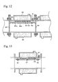
- Fig. 12 is a cross sectional view showing another example of a generation zone of the tunnel-type furnace.
- This example shown in Fig. 12 is a variation of the tunnel-type furnace shown in Figs. 7 and 8.
- This generation zone is equipped with an inner tube 81, a heat receiving member 82, plural thermoelectric conversion modules 83, and a water jacket 84.
- the heat receiving member 82 is provided in the inner tube 81.
- the plural thermoelectric conversion modules 83 are disposed between at least a part of the inner face of the inner tube 81 and the heat receiving member 82 so as to be away from each other.
- the part of the inner face of the inner tube 81 has the upper portion and both side portions (not shown) of the inner face of the inner tube 81.
- the water jacket 84 covers the plural thermoelectric conversion modules 83 in accordance with the provided positions of the thermoelectric conversion modules 83.
- This generation zone has a structure such that a non-oxidizing gas is flowed in the inner tube 81.
- thermoelectric conversion modules 83 can be prevented from being oxidized by the atmosphere gas in the tunnel-type furnace in the same manner as the generation zone shown in Figs. 7 and 8.
- This example has the following structure. That is, the thermoelectric conversion modules 83 are provided in the inner tube 81.
- the heat receiving member 82 prevents the thermoelectric conversion modules 83 from falling therefrom.
- the heat receiving member 82 receives heat.
- the heat receiving member 82 is favorably made of copper, and has plural fins 82a as shown in Fig. 12 so as to have good heat receiving properties.
- the respective members of the example of the generation zone are assembled as follows.
- the inner tube 81 is placed such that predetermined faces thereof are directed downward, and the thermoelectric conversion modules 83 are mounted to the predetermined faces via bonding agents such as copper pastes.
- the thermoelectric conversion modules 83 are covered with the heat receiving member 82, and a wedge is driven by using a rod in the heat receiving member 82 and the inner face of the inner tube 81 facing the heat receiving member 82 so that the heat receiving member 82 is prevented from moving.
- the heat receiving member 82 is fixed by using fixing angle members 85 with an appropriate strength, and the rod is removed therefrom.
- the above operations are performed in turn on predetermined faces of the inner tube 81, which the thermoelectric conversion modules83 are planned to be provided.
- Heat resistant sheets 86 are provided among the fixing angle members 85.
- the generation zone assembled in the above manner is used for connecting zones, which are next to the inner tube 81 as shown in Fig. 12.
- Fig. 13 is a cross sectional view showing another example of a generation zone of the tunnel-type furnace.
- This example shown in Fig. 13 is a variation of the tunnel-type furnace shown in Fig. 12.
- This example is different from the generation zone shown in Fig. 12 in that the heat receiving member 82 is fastened by bolts 87 welded to the inner tube 81.
- This example can yield the same effects as the example shown in Fig. 12.
- Fig. 14 is an axial sectional view showing a connected form of the generation zone shown in Fig. 12 and 13. As shown in Fig. 14, plural thermoelectric conversion modules 83 are provided to the upper curved face and both side faces of the inner tube 81, and an endless belt 87 is passed on the lower side face thereof.
- Figs. 15A to 15C are cross sectional views showing a part of the connected form of the generation zone shown in Fig. 14.
- no bonding agent is used for connecting the inner tube 81, plural thermoelectric conversion modules 83, and the heat receiving member 82.
- a bonding agent 88 is used only for connecting the inner tube 81 and the thermoelectric conversion module 83.
- bonding agents 88 are used for connecting the inner tube 81 and the thermoelectric conversion module 83 and for connecting the thermoelectric conversion module 83 and the heat receiving member 82.
- the bonding agents can be appropriately selected. In a case in which the provided face is large and is not smooth and/or in a case the inner tube 81 which does not have a good surface state is connected thereto, gaps are filled by using bonding agents so as to improve thermal conductivity therein.
- Fig. 16 is a cross sectional view showing another example of a generation zone of the tunnel-type furnace.
- Fig. 17 is a cross sectional view showing the detail of a mounted structure of respective members shown in Fig. 16.
- this generation zone is equipped with an inner tube 91, hooks 92, plural thermoelectric conversion modules 93, rivets 94, a heat receiving member 95, and a water jacket 96.
- the hooks 92 have a T-shaped portion in a cross section thereof, and are connected to the inner tube 91.
- the thermoelectric conversion modules 93 are supported by the hooks 92 at at least a part of the inner face of the inner tube 91 so as to be away from each other.
- the part of the inner face of the inner tube 91 has the upper portion and both side portions (not shown) of the inner face of the inner tube 91.
- the heat receiving member 95 is fastened by the rivets 94 at sides of the thermoelectric conversion modules 93.
- the sides of thermoelectric conversion modules 93 are opposite to the inner tube 91.
- the water jacket 96 covers the inner tube 91 in accordance with the provided positions of the thermoelectric conversion modules 93.
- This generation zone has a structure such that a non-oxidizing gas is flowed in the inner tube 91.
- the respective members of the example of the generation zone are assembled as follows. For example, first, the hooks 92 having a T-shaped portion in a cross section are welded in the inner tube 91, and bonding agents 97 are coated on a predetermined face of the inner tube 91. Next, the thermoelectric conversion module 93 is mounted so as to be fitted into a recessed portion between the hooks 92, and is screwed thereto. In this case, copper plates 93a and 93b of the thermoelectric conversion module 93 are broadened. Copper plate main body portions 95b of the heat receiving member 95 having plural fins 95a and the outside copper plates 93b of the thermoelectric conversion modules 93 are fastened by the rivets 94 to each other.
- the heating zone has thermal insulation by providing bricks, etc., to the heating zone, and the generation zone is provided between the heating zone and the cooling zone, whereby the thermoelectric conversion module can have good thermal efficiency.
- the above thermoelectric conversion module can be provided to the outer face of the tunnel-type furnace, and the tunnel-type furnace thereby facilitates the maintenance thereof.
- the thermoelectric conversion modules can be provided to the outer face of the tunnel-type furnace, and thermal stress relieving members can be used as a component member of the thermoelectric conversion module.
- thermoelectric conversion module can be prevented from being peeled and falling from the tunnel-type furnace during the operation of the tunnel-type furnace. Since the non-oxidizing gas is charged in the space, there is no possibility that the thermoelectric conversion module may be oxidized and may be deteriorated during the operation of the tunnel-type furnace. Therefore, the tunnel-type furnace can have long-term stable performance.
- thermoelectric conversion elements of the thermoelectric conversion module have SiGe elements
- the respective thermoelectric conversion elements can yield an output of 5W.
- the generation zone can be expected to yield an output of 10 kW in total, and can yield an approximate output of 61,300 kWh in a year.
- the generated electricity can be used for lighting a work environment, for operating a control temperature measurement device, etc., and for driving a motor which is for re-cooling cooling water of which the temperature rose after being discharged from the furnace.
Abstract
Description
- The present invention relates to thermoelectric energy conversion units using the Seebeck effect which convert heat energy to electric energy, and relates to tunnel-type furnaces therewith. In particular, the present invention relates to a tunnel-type furnace which provides good thermal efficiency, facilitates the maintenance thereof, and has long-term stable performance.
- Direct generation systems generate electricity by using thermoelectric conversion modules having thermoelectric conversion elements. The direct generation systems are simply constructed and do not have moving portions, thereby having high reliability and facilitating maintenance thereof. However, the direct generation systems have low output density and low energy conversion efficiency. Due to this, research has been performed only on apparatuses for the direct generation systems for special use which have low output scale, such as for spacecraft. However, direct generation systems are recently anticipated to be applied to generation systems using waste heat generated from refuse incinerators in order to conserve resources. As a result, the reduction of the generation cost, the durability of the thermoelectric conversion modules, etc., may be favorably improved.
- The above thermoelectric conversion modules can be applied to endless belt-type furnaces, pusher-type furnaces for powder metallurgy, or furnaces for ceramics heated in air atmospheres, etc. These furnaces are referred to as "tunnel-type furnaces" hereinafter. Specifically, thermoelectric conversion modules can generate electricity by using the waste heat generated from the tunnel-type furnaces, and the generated electricity can be used for operations of electric furnaces. A technique having the thermoelectric conversion modules is disclosed in, for example, Japanese Unexamined Patent Application Publication No. 2002-171776 as described below. That is, a thermoelectric generation device for industrial furnaces is constructed such that a thermoelectric conversion module provided with a ceramic and a graphite is provided at the inside faces of a temperature raising zone, a heating zone, and a cooling zone of endless belt-type continuous furnaces.
- However, in the technique in the above Japanese Unexamined Patent Application Publication No. 2002-171776, when a thermoelectric conversion module is provided in the temperature raising zone or the heating zone, heat loss occurs due to a cooling device cooling the thermoelectric conversion module, and good thermal efficiency cannot be obtained overall. In the above technique, since the thermoelectric conversion module is provided at the inner face of the furnace, it is difficult to perform maintenance thereon, and repair work on the thermoelectric conversion module cannot be performed during the operation of the furnace. The above technique employs a construction such that the thermoelectric conversion module is suspended from the wall of the furnace. Since the suspended structure and the insufficiency of the heat stress relieving device among each member of the thermoelectric conversion module are coupled, the thermoelectric conversion module may possibly peel off and fall therefrom. The thermoelectric conversion module is in an oxidizing atmosphere, and it is thereby oxidized and functions deteriorate. Due to this, the furnace cannot have long-term stable performance.
- Objects of the present invention are to provide a thermoelectric energy conversion unit which has good thermal efficiency and to provide a tunnel-type furnace, having the thermoelectric energy conversion unit, which facilitates the maintenance thereof and has long-term stable performance.
- The present invention provides a thermoelectric energy conversion unit comprising: a thermoelectric conversion module having plural thermoelectric conversion elements disposed away from each other; a heat receiving member; a cooling member, the cooling member and the heat receiving member holding the thermoelectric conversion module; and a non-oxidizing gas charged in a space formed between the heat receiving member and the cooling member.
- According to the thermoelectric energy conversion unit of the present invention, since the non-oxidizing gas is charged in the space formed between the heat receiving member and the cooling member, the thermoelectric energy conversion unit is not oxidized, thereby being prevented from functionally deteriorating. Since the thermoelectric energy conversion unit has the above structure, the thermoelectric energy conversion unit is easily provided not only to new equipment but also to conventional equipment. In this case, when binders are filled in gaps formed between the thermoelectric energy conversion unit and the other members of the above equipment, the thermal conductivity thereof can be further improved so that generation performance is improved.
- For example, the thermoelectric conversion module may be constructed such that plural thermoelectric elements, which are connected to each other by connecting pads, are disposed between copper plates so as to form an approximate square of 25 mm X 25 mm. The connecting pad may be the following multi-layered structural member. That is, an electrical insulator is disposed between copper plates having good electrical conductivity and thermal conductivity, and mixed middle layers are provided between the electrical insulator and the copper plates so as to relieve the difference in thermal stress which results from the difference in the coefficients of thermal expansion thereof. The connecting pad may have an overall good thermal conductivity, an electrical connection function among the thermoelectric conversion elements, an electrical insulation portion of a heat receiving side and a heat discharging side thereof, a temperature gradient therebetween, and a stress relieving function based on the thermal expansion difference between the copper plate and the electrical insulator. The component members of the connecting pad can be integrally or separately produced by using a powder metallurgy method.
- The present invention provides a tunnel-type furnace including: a heating zone; a cooling zone, wherein heated bodies are transferred in turn in the heating zone and the cooling zone; and the above thermoelectric energy conversion unit provided between the heating zone and the cooling zone.
- According to the tunnel-type furnace of the present invention, for example, bricks, etc., are provided to the heating zone so that the heating zone is thermally insulated, and a generation portion is provided between the heating zone and the cooling zone, whereby the thermoelectric conversion module can have good thermal efficiency. Since the above thermoelectric conversion module is used in the tunnel-type furnace of the present invention, for example, the above thermoelectric conversion module can be provided to the outer face of the tunnel-type furnace, and the tunnel-type furnace thereby facilitates the maintenance thereof. In the tunnel-type furnace of the present invention, the thermoelectric conversion modules can be provided to the outer face of the tunnel-type furnace, and thermal stress relieving members can be used as a component member of the thermoelectric conversion module. For example, the thermal stress relieving member may be a mixed material having a predetermined mixing ratio of respective components. As a result, the thermoelectric conversion module can be prevented from peeling off and falling from the tunnel-type furnace during the operation of the tunnel-type furnace. Since the non-oxidizing gas is charged in the space, there is no possibility that the thermoelectric conversion module will be oxidized and will be deteriorated during the operation of the tunnel-type furnace. Therefore, the tunnel-type furnace can have long-term stable performance.
-
- Fig. 1 is a cross sectional view showing a general structure of a conventional mesh belt-type furnace;
- Fig. 2 is a cross sectional view showing a general structure of a mesh belt-type furnace in one embodiment according to the present invention;
- Fig. 3 is a cross sectional view showing another general structure of a mesh belt-type furnace in one embodiment according to the present invention;
- Figs. 4A and 4B are cross sectional views showing a thermoelectric conversion module in one embodiment according to the present invention;
- Figs. 5A to 5D are cross sectional views showing a desirable form of a thermoelectric conversion module in one embodiment according to the present invention;
- Figs. 6A and 6B are upper face views showing an example of a connecting line of thermoelectric conversion modules shown in Figs. 5A to 5D;
- Fig. 7 is a cross sectional view showing an example of a generation zone of the tunnel-type furnace;
- Fig. 8 is an axial sectional view of the generation zone shown in Fig. 7;
- Fig. 9 is a cross sectional view showing another example of a generation zone of the tunnel-type furnace;
- Fig. 10 is a cross sectional view showing another example of a generation zone of the tunnel-type furnace;
- Fig. 11 is a cross sectional view showing a structure for outputting electricity generated in the generation zone shown in Figs. 7 to 10;
- Fig. 12 is a cross sectional view showing another example of a generation zone of the tunnel-type furnace;
- Fig. 13 is a cross sectional view showing another example of a generation zone of the tunnel-type furnace;
- Fig. 14 is an axial sectional view showing a connected form of the generation zone shown in Fig. 12 and 13;
- Figs. 15A and 15B are cross sectional views showing a part of the connected form of the generation zone shown in Fig. 14;
- Fig. 16 is a cross sectional view showing another example of a generation zone of the tunnel-type furnace; and
- Fig. 17 is a cross sectional view showing details of a mounted structure of respective members shown in Fig.16.
-
- One embodiment of the present invention will be described hereinafter with reference to the Figures. Fig. 1 is a cross sectional view showing a general structure of a conventional mesh belt-type furnace (tunnel-type furnace). The furnace shown in Fig. 1 is divided into three units, that is, a preheating
zone 1, aheating zone 2, and acooling zone 3. Aninner tube 1a in thepre-heating zone 1, aninner tube 2a in theheating zone 2, and aninner tube 3a in thecooling zone 3 are joined with each other. An endless belt 4 is continuously passed through theinner tubes - In the
pre-heating zone 1, aheater 1b is mounted around theinner tube 1a, and heat resisting bricks 1c are packed around the outside of theheater 1b. In theheating zone 2, aheater 2b is mounted around theinner tube 2a, andheat resisting bricks 2c are packed around the outside of theheater 2b. In thecooling zone 3, awater jacket 3b is mounted around theinner tube 3a. Theheater inner tubes 1a to 3a. For example, the reducing gas is a hydrogen gas or a mixed gas of a hydrogen gas and a nitrogen gas. - When the above furnace is used, the temperature of the
heating zone 2 is set as follows. That is, when theheating zone 2 is used for sintering an iron-type alloy, the temperature thereof is set from 1100°C to 1200°C. When theheating zone 2 is for sintering a copper alloy, the temperature thereof is set from 750°C to 780°C. The furnace surface temperature of the preheatingzone 1 and theheating zone 2 is about 500°C. When the sintered work holding heat on the endless belt 4 is moved to thecooling zone 3, the sintered work is cooled by thewater jacket 3b so as to prevent oxidation, and the sintered work is removed therefrom. The cooling water is supplied to thewater jacket 3b at any time, and the heated water is led to a pool, etc., so as to discharge heat in the air. Alternatively, the cooling water is cooled by a cooling device and is recycled. Thermoelectric conversion modules of the present invention are not provided in the tunnel-type furnace shown in Fig. 1. - Fig. 2 is a cross sectional view showing a general structure of a mesh belt-type furnace in one embodiment according to the present invention. The mesh belt-type furnace in Fig. 2 is divided into four units, that is, a preheating
zone 11, aheating zone 12, acooling zone 13, and ageneration zone 14 placed between theheating zone 12 and thecooling zone 13. Aninner tube 11a in the preheatingzone 11, aninner tube 12a in theheating zone 12, aninner tube 13a in thecooling zone 13, and aninner tube 14a in thegeneration zone 14 are joined with each other. Anendless belt 15 is continuously passed through theinner tubes - The preheating
zone 11, theheating zone 12, the coolingzone 13 have the same structures as of the conventional mesh belt-type furnace as shown in Fig. 1. Thegeneration zone 14 is constructed such thatthermoelectric conversion modules 14b are mounted around theinner tube 14a. A reducing gas is in theinner tubes - Since the
generation zone 14 including theinner tube 14a is put between theheating zone 12 and thecooling zone 13 as described the above, the generation efficiency of thethermoelectric conversion modules 14b is increased. As shown in Fig. 3, two generation zones, that is, ageneration zone 14 and ageneration zone 15, can be disposed between theheating zone 12 and thecooling zone 13. For example,thermoelectric conversion modules inner tubes thermoelectric conversion modules thermoelectric conversion module 14b of the higher temperature side can have SiGe elements, and thethermoelectric conversion module 15b of the lower temperature side can have PbTe elements. The SiGe element exhibits the highest generation performance at about 830°C, and the PbTe element exhibits the highest generation performance at about 400°C. Therefore, the SiGe element can efficiently generate electricity in a temperature range from 450°C to 900°C in accordance with the temperature of thecooling zone 13 of the furnace, and the PbTe element can efficiently generate electricity in a temperature range from 200°C to 450°C in accordance with the temperature of thecooling zone 13 of the furnace. - The thermoelectric conversion modules used in the
generation zones - Figs. 4A and 4B are cross sectional views showing a part of a thermoelectric conversion module in one embodiment according to the present invention. The thermoelectric conversion modules as shown in Figs. 4A and 4B have P-type
thermoelectric conversion elements 21, N-typethermoelectric conversion elements 22, and connectingpads 23 connecting theelements pads 23. - The connecting
pads 23 connect theelements pads 23 shown in Figs. 4A and 4B can be produced by multi-layered powder compacting and by sintering. - As shown in Fig. 4A, the connecting
pads 23 are constructed such that acopper layer 23a, amixed layer 23b of a copper and an alumina, analumina layer 23c, amixed layer 23d of a copper and an alumina, and a copper layer 23e are laminated in turn on the side of theelements pad 23 is constructed such that acopper layer 23f, amixed layer 23g of a copper and an alumina, and analumina layer 23h are laminated in turn on the side of theelements mixed layers mixed layers - The
layers 23a to 23h of thebonding pads 23 shown in Fig. 4A and 4B can be connected with each other via a bonding agent such as a binder. Alternatively, thelayers 23a to 23h of the connectingpads 23 are simply laminated in turn and can be held by an appropriate joining device so as to be connected with each other. These above connecting techniques can be applied in order to prevent a slip between the alumina layer 27h and the copper plate (not shown) contacting the alumina layer 27h when the connectingpad 23 shown in Fig. 4B is constructed such that thealumina layer 23h is exposed. The copper plate is a heat receiving plate or a heat discharging member. - A mixed agent of a carbon-type material and a binder, a copper paste in which copper powder is dispersed on a silicate glass, or a silver paste in which silver powder is dispersed on a silicate glass can be used as the above bonding agent. When the mixed agent is used, a low melting point glass can be favorably used on the higher temperature side (the heat receiving plate side), and a resin-type material can be favorably used on the lower temperature side (the heat discharging plate side). The above binder has an adhering function of the respective members, a fixing function, a filling function of irregularities between the members, a thermal conducting function, and an electrical conducting function. The above binder can be selected in accordance with a category temperature and a binding position.
- Figs. 5A to 5D are cross sectional views showing a favorable form of the thermoelectric conversion module in one embodiment according to the present invention. The thermoelectric conversion modules shown in Figs. 5A to 5D have P-type
thermoelectric conversion modules 31, N-typethermoelectric conversion modules 32, connecting pads connecting theelements copper plates pads 33. - In an example shown in Fig. 5A, the thermoelectric conversion module is constructed such that the
members 31 to 35 are integrated with each other by using a bonding agent and are completely mounted to the plane of the furnace in the later process. In an example shown in Fig. 5B, the thermoelectric conversion module is constructed such that the upper and bottom faces thereof have a cylindrically curved structure and are mounted to a cylindrically curved surface of the furnace. In this example shown in Fig. 5B, the connectingpad 33 has a curved form by powder compacting. In an example shown in Fig. 5C, the thermoelectric conversion module is constructed such that the upper and bottom faces thereof have a cylindrically curved structure in the same manner as the example shown in Fig. 5B. In this example shown in Fig. 5C, thecopper plates 34 and 35 (a heat receiving plate or a heat discharging member) have a curved form by powder compacting. In an example shown in Fig. 5D, the thermoelectric conversion module is constructed such that thecopper plates bolt 36. In this example shown in Fig. 5D, a gap is easily generated among thethermoelectric conversion elements pad 33 as thesemembers bolt 36. Therefore, a bonding agent is desirably applied as a filler to fill the gaps among thesemembers - Figs. 6A and 6B are upper face views showing an example of a connecting line of the thermoelectric conversion modules shown in Figs. 5A to 5D. In an example shown in Fig. 6A, 47 thermoelectric conversion elements are connected in series by heating
side connection lines 42 and cooling side lines 43. In this example shown in Fig. 6A, athermoelectric conversion element 41a and athermoelectric conversion element 41b can be as an output terminal. This example shown in Fig. 6A can be applied to the examples shown in Figs. 5A to 5C. A case in which a bolt is positioned in aspace portion 44 shown in Fig. 6A corresponds to the example shown in Fig. 5D. The surface copper layers of the connecting pads are used as connecting lines in the thermoelectric conversion module. As described the above, the output terminals of the thermoelectric conversion modules are connected with each other. In this case, the electricity generated by the thermoelectric conversion modules is output to a storage battery via a converter or is output to an auxiliary device such as lighting via a transformer. In the other example shown in Fig. 6B, 42elements 41 are connected in series. - The above examples are desirable thermoelectric conversion modules of the present invention. Desirable examples of tunnel-type furnaces having the thermoelectric conversion modules of the present invention will be described hereinafter.
- Fig. 7 is a cross sectional view showing an example of a generation zone of the tunnel-type furnace. This generation zone is equipped with an
inner tube 51, pluralthermoelectric conversion modules 52, and awater jacket 53. The pluralthermoelectric conversion modules 52 are disposed at at least a part of the outer face of theinner tube 51 so as to be disposed away from each other. That is, as shown in Fig.7, the pluralthermoelectric conversion modules 52 are disposed at the upper portion and both side portions (not shown) of the outer face of theinner tube 51. Thewater jacket 53 covers the pluralthermoelectric conversion modules 52. In this generation zone, aspace 55 is formed between theinner tube 51 and thewater jacket 53,plural holes 56 are formed so as to communicate from theinner tube 51 to thespace 55, and agas discharging tube 57, which communicates from thespace 55 to an outside, is formed so that a non-oxidizing gas is flowed from the inside 54 of theinner tube 51 to the outside via thespace 55. Aseal 58 is provided between theinner tube 51 and the bottom plate of thewater jacket 53 so as to form a seal therebetween. The above non-oxidizing gas is desirably hydrogen or a mixed gas of a hydrogen gas and a nitrogen gas. The mixed gas includes a dissociated ammonia gas. - In the above structure of the tunnel-type furnace shown in Fig. 7, the temperature of the
inner tube 51 increases by the heat of the work which is heated on the endless belt (not shown). The one ends of thethermoelectric conversion modules 52 are heated by the heat of theinner tube 51 gained by the temperature rise. The other ends of thethermoelectric conversion modules 52 are cooled by thewater jacket 53. As a result, thethermoelectric conversion modules 52 generate electricity based on the Seebeck effect in accordance with the above temperature differences between the one ends and the other ends of thethermoelectric conversion modules 52. Thethermoelectric conversion modules 52 have a relatively high temperature during the use of the furnace. The temperature is so high that thethermoelectric conversion modules 52 are oxidized in the air. However, thethermoelectric conversion modules 52 are prevented from being oxidized and being deteriorated since the non-oxidizing gas is flowed in gaps which are formed among thethermoelectric conversion modules 52 which are next to each other and are formed among the elements of thethermoelectric conversion modules 52, which are next to each other. The combustion disposal is performed on the non-oxidizing gas discharged to the outside. - Fig. 8 is a axial sectional view of the generation zone shown in Fig. 7. The respective members of the generation zone are placed and fixed as follows. For example, the
inner tube 51 is placed such that predetermined faces thereof are directed upward, thethermoelectric conversion modules 52 are mounted to the predetermined faces via bonding agents such as copper pastes coated thereon, and are connected with each other. Next, bonding agents are coated on the copper plates placed on the top faces of thethermoelectric conversion modules 52, and then thewater jacket 53 is mounted thereto and is fastened by bolts. The above operations are performed in turn on predetermined faces of theinner tube 51, on which the thermoelectric conversion modules are planned to be provided. The above bonding agents may have thermo-plastic properties and can be used as they are. The above bonding agents are used for filling the gaps formed in the contacted portions of the respective members and for improving thermal conductivities thereof. The above bonding agents are therefore of a carbon-type, are favorably of a copper-type, and are more favorably of a silver-type. The generation zone assembled in the above manner is used by connecting zones (shown as dotted portions), which are next to theinner tube 51. The above tunnel-type furnace is one example, and the respective members thereof can be arranged and fixed in various manners other than the above manner. - Fig. 9 is a cross sectional view showing another example of a generation zone of the tunnel-type furnace. This generation zone is equipped with an
inner tube 61, pluralthermoelectric conversion modules 62, and awater jacket 63. The pluralthermoelectric conversion modules 62 are disposed at at least a part of the outer face of theinner tube 61 so as to be away from each other. That is, as shown in Fig.9, the pluralthermoelectric conversion modules 62 are disposed at the upper portion and both side portions (not shown) of the outer face of theinner tube 61. Thewater jacket 63 covers the pluralthermoelectric conversion modules 62. In this generation zone, aspace 64 is formed between theinner tube 61 and thewater jacket 63. Agas supplying tube 65 and agas discharging tube 66, which communicate from an outside to thespace 64, are formed so that a non-oxidizing gas is flowed from the outside to the outside via thespace 64. - In the above structure of the tunnel-type furnace, even when the inside of the
inner tube 61 is under an oxidizing gas such as the air, thethermoelectric conversion modules 62 are prevented from being oxidized and being deteriorated since the non-oxidizing gas is in thespace 64 which is isolated from the inside of theinner tube 61. - Fig. 10 is a cross sectional view showing another example of a generation zone of the tunnel-type furnace. This example shown in Fig. 10 is a variation of the tunnel-type furnace shown in Fig. 9. This example is different from the generation zone as shown in Fig. 9 in that the
thermoelectric conversion modules 62 and thewater jacket 63 are removably provided to each other. That is, thethermoelectric conversion modules 62 are not directly connected to the bottom portion of thewater jacket 63, and a dividingmember 67 is separately mounted between themembers - In the above structure of the tunnel-type furnace, it is easy to assemble and repair the
thermoelectric conversion modules 62 and thewater jacket 63. Since gaps are easily formed among thethermoelectric conversion modules 62 and thewater jacket 63 when thesemembers gas tube 68, and thespace 64 can be degassed by the vacuum pump so that the pressure thereof is reduced, instead of circulating the non-oxidizing gas in thespace 64 in which thethermoelectric conversion modules 62 are provided. - Fig. 11 is a cross sectional view showing a structure for outputting electricity generated in the various structures of generation zones shown in Figs. 7 to 10. The structure for outputting electricity is as follows. For example, a
hole 72 penetrates acooling plate 71 contacting the water jacket. Aninsulator member 75 of a ceramic is mounted to thehole 72 via aseal member 76. Positive andnegative copper lines insulator member 75. The positive andnegative copper lines thermoelectric conversion module 77 is led to an outside. When athermoelectric conversion module 77 is in a degassed decompressed state, and a vacuumpump connecting opening 78 is favorably provided as shown in Fig. 11. - Fig. 12 is a cross sectional view showing another example of a generation zone of the tunnel-type furnace. This example shown in Fig. 12 is a variation of the tunnel-type furnace shown in Figs. 7 and 8. This generation zone is equipped with an
inner tube 81, aheat receiving member 82, pluralthermoelectric conversion modules 83, and awater jacket 84. Theheat receiving member 82 is provided in theinner tube 81. The pluralthermoelectric conversion modules 83 are disposed between at least a part of the inner face of theinner tube 81 and theheat receiving member 82 so as to be away from each other. The part of the inner face of theinner tube 81 has the upper portion and both side portions (not shown) of the inner face of theinner tube 81. Thewater jacket 84 covers the pluralthermoelectric conversion modules 83 in accordance with the provided positions of thethermoelectric conversion modules 83. This generation zone has a structure such that a non-oxidizing gas is flowed in theinner tube 81. - In this structure of the example of the generation zone as shown in Fig. 12, the
thermoelectric conversion modules 83 can be prevented from being oxidized by the atmosphere gas in the tunnel-type furnace in the same manner as the generation zone shown in Figs. 7 and 8. This example has the following structure. That is, thethermoelectric conversion modules 83 are provided in theinner tube 81. Theheat receiving member 82 prevents thethermoelectric conversion modules 83 from falling therefrom. Theheat receiving member 82 receives heat. Theheat receiving member 82 is favorably made of copper, and hasplural fins 82a as shown in Fig. 12 so as to have good heat receiving properties. - The respective members of the example of the generation zone are assembled as follows. For example, the
inner tube 81 is placed such that predetermined faces thereof are directed downward, and thethermoelectric conversion modules 83 are mounted to the predetermined faces via bonding agents such as copper pastes. Next, thethermoelectric conversion modules 83 are covered with theheat receiving member 82, and a wedge is driven by using a rod in theheat receiving member 82 and the inner face of theinner tube 81 facing theheat receiving member 82 so that theheat receiving member 82 is prevented from moving. Finally, theheat receiving member 82 is fixed by using fixingangle members 85 with an appropriate strength, and the rod is removed therefrom. The above operations are performed in turn on predetermined faces of theinner tube 81, which the thermoelectric conversion modules83 are planned to be provided. Heatresistant sheets 86 are provided among the fixingangle members 85. The generation zone assembled in the above manner is used for connecting zones, which are next to theinner tube 81 as shown in Fig. 12. - Fig. 13 is a cross sectional view showing another example of a generation zone of the tunnel-type furnace. This example shown in Fig. 13 is a variation of the tunnel-type furnace shown in Fig. 12. This example is different from the generation zone shown in Fig. 12 in that the
heat receiving member 82 is fastened bybolts 87 welded to theinner tube 81. This example can yield the same effects as the example shown in Fig. 12. - Fig. 14 is an axial sectional view showing a connected form of the generation zone shown in Fig. 12 and 13. As shown in Fig. 14, plural
thermoelectric conversion modules 83 are provided to the upper curved face and both side faces of theinner tube 81, and anendless belt 87 is passed on the lower side face thereof. - Figs. 15A to 15C are cross sectional views showing a part of the connected form of the generation zone shown in Fig. 14. In the example shown in Fig. 15A, no bonding agent is used for connecting the
inner tube 81, pluralthermoelectric conversion modules 83, and theheat receiving member 82. In the example shown in Fig. 15B, abonding agent 88 is used only for connecting theinner tube 81 and thethermoelectric conversion module 83. In the example shown in Fig. 15C,bonding agents 88 are used for connecting theinner tube 81 and thethermoelectric conversion module 83 and for connecting thethermoelectric conversion module 83 and theheat receiving member 82. In these above examples, the bonding agents can be appropriately selected. In a case in which the provided face is large and is not smooth and/or in a case theinner tube 81 which does not have a good surface state is connected thereto, gaps are filled by using bonding agents so as to improve thermal conductivity therein. - Fig. 16 is a cross sectional view showing another example of a generation zone of the tunnel-type furnace. Fig. 17 is a cross sectional view showing the detail of a mounted structure of respective members shown in Fig. 16. As shown in Figs. 16 and 17, this generation zone is equipped with an
inner tube 91, hooks 92, pluralthermoelectric conversion modules 93, rivets 94, aheat receiving member 95, and awater jacket 96. Thehooks 92 have a T-shaped portion in a cross section thereof, and are connected to theinner tube 91. Thethermoelectric conversion modules 93 are supported by thehooks 92 at at least a part of the inner face of theinner tube 91 so as to be away from each other. The part of the inner face of theinner tube 91 has the upper portion and both side portions (not shown) of the inner face of theinner tube 91. Theheat receiving member 95 is fastened by therivets 94 at sides of thethermoelectric conversion modules 93. The sides ofthermoelectric conversion modules 93 are opposite to theinner tube 91. Thewater jacket 96 covers theinner tube 91 in accordance with the provided positions of thethermoelectric conversion modules 93. This generation zone has a structure such that a non-oxidizing gas is flowed in theinner tube 91. - The respective members of the example of the generation zone are assembled as follows. For example, first, the
hooks 92 having a T-shaped portion in a cross section are welded in theinner tube 91, andbonding agents 97 are coated on a predetermined face of theinner tube 91. Next, thethermoelectric conversion module 93 is mounted so as to be fitted into a recessed portion between thehooks 92, and is screwed thereto. In this case,copper plates thermoelectric conversion module 93 are broadened. Copper platemain body portions 95b of theheat receiving member 95 havingplural fins 95a and theoutside copper plates 93b of thethermoelectric conversion modules 93 are fastened by therivets 94 to each other. - According to the tunnel-type furnaces equipped with a generation zone as shown in Figs. 7, 9, 10, 12, 13, and 16, the heating zone has thermal insulation by providing bricks, etc., to the heating zone, and the generation zone is provided between the heating zone and the cooling zone, whereby the thermoelectric conversion module can have good thermal efficiency. The above thermoelectric conversion module can be provided to the outer face of the tunnel-type furnace, and the tunnel-type furnace thereby facilitates the maintenance thereof. In the above tunnel-type furnaces, the thermoelectric conversion modules can be provided to the outer face of the tunnel-type furnace, and thermal stress relieving members can be used as a component member of the thermoelectric conversion module. As a result, the thermoelectric conversion module can be prevented from being peeled and falling from the tunnel-type furnace during the operation of the tunnel-type furnace. Since the non-oxidizing gas is charged in the space, there is no possibility that the thermoelectric conversion module may be oxidized and may be deteriorated during the operation of the tunnel-type furnace. Therefore, the tunnel-type furnace can have long-term stable performance.
- In the tunnel-type furnace equipped with a generation zone as shown in Figs. 7, 9, 10, 12, 13, and 16, when the thermoelectric conversion elements of the thermoelectric conversion module have SiGe elements, the respective thermoelectric conversion elements can yield an output of 5W. As a result, when two thousand SiGe elements are used, the generation zone can be expected to yield an output of 10 kW in total, and can yield an approximate output of 61,300 kWh in a year. The generated electricity can be used for lighting a work environment, for operating a control temperature measurement device, etc., and for driving a motor which is for re-cooling cooling water of which the temperature rose after being discharged from the furnace.
Claims (10)
- A thermoelectric energy conversion unit comprising:a thermoelectric conversion module having plural thermoelectric conversion elements disposed away from each other;a heat receiving member;a cooling member, the cooling member and the heat receiving member holding the thermoelectric conversion module; anda non-oxidizing gas charged in a space formed between the heat receiving member and the cooling member.
- A tunnel-type furnace comprising:a heating zone;a cooling zone, wherein heated bodies are transferred in turn in the heating zone and the cooling zone; anda thermoelectric energy conversion unit provided between the heating zone and the cooling zone,the thermoelectric energy conversion unit comprising:thermoelectric conversion modules having plural thermoelectric conversion elements disposed away from each other;a heat receiving member;a cooling member, the cooling member and the heat receiving member holding the thermoelectric conversion module; anda non-oxidizing gas charged in a space formed between the heat receiving member and the cooling member.
- The tunnel-type furnace according to claim 2, wherein the furnace further comprising:wherein the thermoelectric conversion modules are disposed at at least on a part of the outer face so as to be away from each other, andan inner tube in which the heated bodies are transferred;a cooling device covering the thermoelectric conversion modules;plural holes provided in at least a part of the inner tube, the plural holes communicating from an inside of the inner tube to a space formed between the inner tube and the cooling device; anda gas discharging portion communicating from the space to an outside,
the non-oxidizing gas is flowed from the inside of the inner tube to the outside via the space. - The tunnel-type furnace according to claim 2, wherein the furnace further comprising:wherein the thermoelectric conversion modules are disposed so as to be away from each other at least at a part of the outer face of the inner tube, andan inner tube in which the heated bodies are transferred;a cooling device covering the thermoelectric conversion modules;a gas supplying portion; anda gas discharging portion, the gas discharging portion and the gas supplying portion communicating from an outside to a space formed between the inner tube and the cooling device,
the non-oxidizing gas is flowed from the outside to the outside via the space. - The tunnel-type furnace according to claim 4, wherein the thermoelectric conversion modules and the cooling device are removably provided to each other.
- The tunnel-type furnace according to claim 2, wherein the furnace further comprising:wherein the heat receiving member is provided in the inner tube, the thermoelectric conversion modules are held between at least a part of the inner face of the inner tube and the heat receiving member provided in the inner tube, andan inner tube in which the heated bodies are transferred; anda cooling device covering the thermoelectric conversion modules in accordance with provided positions of the thermoelectric conversion modules,
the non-oxidizing gas is charged in the inner tube. - The tunnel-type furnace according to claim 6, wherein the furnace further comprising:fixing angle members connected to the inner tube, the fixing angle members supporting the heat receiving member.
- The tunnel-type furnace according to claim 6, wherein the furnace further comprising:bolts welded to the inner tube, the bolts used for fastening the heat receiving member.
- The tunnel-type furnace according to claim 2, wherein the furnace further comprising:wherein the heat receiving member is fastened by the rivets at sides of the thermoelectric conversion modules, the sides of the thermoelectric conversion modules being opposite to the inner tube,an inner tube in which the heated bodies are transferred;a cooling device covering the inner tube in accordance with the provided positions of the thermoelectric conversion modules;hooks connected to the inner tube; andrivets for fastening the heat receiving member,
the thermoelectric conversion modules are supported by the hooks at at least a part of the inner face of the inner tube so as to be disposed away from each other, and
the non-oxidizing gas is charged in the inner tube. - The tunnel-type furnace according to one of claims 6 to 9, wherein the furnace further comprising:plural fins provided at the heat receiving member.
Applications Claiming Priority (2)
| Application Number | Priority Date | Filing Date | Title |
|---|---|---|---|
| JP2003148148 | 2003-05-26 | ||
| JP2003148148A JP2004350479A (en) | 2003-05-26 | 2003-05-26 | Thermoelectric conversion power generating unit and tunnel type furnace equipped with same |
Publications (2)
| Publication Number | Publication Date |
|---|---|
| EP1482568A2 true EP1482568A2 (en) | 2004-12-01 |
| EP1482568A3 EP1482568A3 (en) | 2007-02-28 |
Family
ID=33128206
Family Applications (1)
| Application Number | Title | Priority Date | Filing Date |
|---|---|---|---|
| EP04012367A Withdrawn EP1482568A3 (en) | 2003-05-26 | 2004-05-25 | Thermoelectric energy conversion unit and tunnel-type furnace therewith |
Country Status (3)
| Country | Link |
|---|---|
| US (1) | US20050056310A1 (en) |
| EP (1) | EP1482568A3 (en) |
| JP (1) | JP2004350479A (en) |
Cited By (15)
| Publication number | Priority date | Publication date | Assignee | Title |
|---|---|---|---|---|
| WO2008042073A3 (en) * | 2006-09-28 | 2009-04-09 | Rosemount Inc | Pipeline thermoelectric generator assembly |
| DE102008054946A1 (en) | 2008-12-19 | 2010-06-24 | Endress + Hauser Wetzer Gmbh + Co. Kg | Protective housing device for receiving e.g. field device, of process automation unit, has thermal blocking filter provided with thermally absorbent and/or thermally insulating functional material |
| US7913566B2 (en) | 2006-05-23 | 2011-03-29 | Rosemount Inc. | Industrial process device utilizing magnetic induction |
| US7957708B2 (en) | 2004-03-02 | 2011-06-07 | Rosemount Inc. | Process device with improved power generation |
| US7977924B2 (en) | 2008-11-03 | 2011-07-12 | Rosemount Inc. | Industrial process power scavenging device and method of deriving process device power from an industrial process |
| US8145180B2 (en) | 2004-05-21 | 2012-03-27 | Rosemount Inc. | Power generation for process devices |
| AT510473A1 (en) * | 2010-09-21 | 2012-04-15 | Miba Sinter Austria Gmbh | THERMO GENERATOR |
| US8188359B2 (en) | 2006-09-28 | 2012-05-29 | Rosemount Inc. | Thermoelectric generator assembly for field process devices |
| US8250924B2 (en) | 2008-04-22 | 2012-08-28 | Rosemount Inc. | Industrial process device utilizing piezoelectric transducer |
| CN103166523A (en) * | 2011-12-14 | 2013-06-19 | 中国钢铁股份有限公司 | Method and device for recovering waste heat of heating furnace wall and generating electricity |
| US8538560B2 (en) | 2004-04-29 | 2013-09-17 | Rosemount Inc. | Wireless power and communication unit for process field devices |
| US8929948B2 (en) | 2008-06-17 | 2015-01-06 | Rosemount Inc. | Wireless communication adapter for field devices |
| WO2015021956A1 (en) * | 2013-08-12 | 2015-02-19 | Gentherm Gmbh | Electricity generation unit for converting heat into electrical energy |
| CN105226998A (en) * | 2015-09-30 | 2016-01-06 | 天津大学 | A kind of temperature difference electricity generation device and electric power system utilizing boiler slag-cooling hydro-thermal amount |
| DE102011056153C5 (en) * | 2011-12-08 | 2019-02-28 | Benteler Automobiltechnik Gmbh | Impact surface heat exchanger for arrangement in an exhaust system of a motor vehicle |
Families Citing this family (40)
| Publication number | Priority date | Publication date | Assignee | Title |
|---|---|---|---|---|
| US7587901B2 (en) | 2004-12-20 | 2009-09-15 | Amerigon Incorporated | Control system for thermal module in vehicle |
| JP4661235B2 (en) * | 2005-01-27 | 2011-03-30 | 株式会社Ihi | Thermoelectric converter |
| JP4808425B2 (en) * | 2005-03-22 | 2011-11-02 | 光洋サーモシステム株式会社 | Heat treatment equipment |
| JP2007051332A (en) * | 2005-08-18 | 2007-03-01 | Koyo Thermo System Kk | Hardening device, and method for recovering exhaust heat of coolant |
| US20070101737A1 (en) | 2005-11-09 | 2007-05-10 | Masao Akei | Refrigeration system including thermoelectric heat recovery and actuation |
| US7310953B2 (en) * | 2005-11-09 | 2007-12-25 | Emerson Climate Technologies, Inc. | Refrigeration system including thermoelectric module |
| JP4928182B2 (en) * | 2006-07-10 | 2012-05-09 | 株式会社プランテック | Thermoelectric conversion system and its construction method |
| JP5087875B2 (en) * | 2006-07-31 | 2012-12-05 | 株式会社Ihi | Heat treatment equipment |
| US20080087316A1 (en) | 2006-10-12 | 2008-04-17 | Masa Inaba | Thermoelectric device with internal sensor |
| US9105809B2 (en) * | 2007-07-23 | 2015-08-11 | Gentherm Incorporated | Segmented thermoelectric device |
| US20090031733A1 (en) * | 2007-07-31 | 2009-02-05 | General Electric Company | Thermotunneling refrigeration system |
| US7877827B2 (en) | 2007-09-10 | 2011-02-01 | Amerigon Incorporated | Operational control schemes for ventilated seat or bed assemblies |
| CN101932475A (en) | 2008-02-01 | 2010-12-29 | 阿美里根公司 | Condensation and humidity sensors for thermoelectric devices |
| CN102098947B (en) | 2008-07-18 | 2014-12-10 | 阿美里根公司 | Climate controlled bed assembly |
| DE102008063701A1 (en) * | 2008-12-19 | 2010-06-24 | Behr Gmbh & Co. Kg | Exhaust gas cooler for an internal combustion engine |
| CA2768803A1 (en) * | 2009-07-27 | 2011-02-03 | Basf Se | Thermoelectric modules with improved contact connection |
| DE102010036188A1 (en) | 2009-10-28 | 2011-05-05 | Sms Siemag Ag | Process for energy recovery in metallurgical plants and metallurgical plant on the basis of thermocouples |
| KR101260776B1 (en) | 2010-04-15 | 2013-05-06 | 한라비스테온공조 주식회사 | Thermoelectric Power Generating Heat Exchanger |
| JP5712791B2 (en) * | 2011-05-25 | 2015-05-07 | 日産自動車株式会社 | Waste heat power generator |
| JP2013002764A (en) * | 2011-06-20 | 2013-01-07 | Nissan Motor Co Ltd | Controlled cooling furnace |
| JP6246998B2 (en) * | 2011-07-27 | 2017-12-13 | Jfeスチール株式会社 | Thermoelectric power generation apparatus and thermoelectric power generation method |
| WO2013052823A1 (en) | 2011-10-07 | 2013-04-11 | Gentherm Incorporated | Thermoelectric device controls and methods |
| JP5737139B2 (en) * | 2011-11-04 | 2015-06-17 | トヨタ自動車株式会社 | Thermoelectric generator |
| JP5737151B2 (en) * | 2011-11-18 | 2015-06-17 | トヨタ自動車株式会社 | Thermoelectric generator |
| US9989267B2 (en) | 2012-02-10 | 2018-06-05 | Gentherm Incorporated | Moisture abatement in heating operation of climate controlled systems |
| JP5951438B2 (en) * | 2012-10-05 | 2016-07-13 | 光洋サーモシステム株式会社 | Heat treatment equipment |
| KR101390688B1 (en) | 2012-10-25 | 2014-04-30 | 현대자동차주식회사 | Thermoelectric generator for vehicle |
| JP5765363B2 (en) * | 2013-04-16 | 2015-08-19 | トヨタ自動車株式会社 | Thermoelectric generator |
| DE102013104806A1 (en) * | 2013-05-08 | 2014-11-13 | Sandvik Materials Technology Deutschland Gmbh | belt furnace |
| US9662962B2 (en) | 2013-11-05 | 2017-05-30 | Gentherm Incorporated | Vehicle headliner assembly for zonal comfort |
| CN111016756B (en) | 2014-02-14 | 2023-08-08 | 金瑟姆股份公司 | Conductive convection climate control assembly |
| US11857004B2 (en) | 2014-11-14 | 2024-01-02 | Gentherm Incorporated | Heating and cooling technologies |
| WO2016077843A1 (en) | 2014-11-14 | 2016-05-19 | Cauchy Charles J | Heating and cooling technologies |
| US11639816B2 (en) | 2014-11-14 | 2023-05-02 | Gentherm Incorporated | Heating and cooling technologies including temperature regulating pad wrap and technologies with liquid system |
| KR101755855B1 (en) | 2015-10-06 | 2017-07-07 | 현대자동차주식회사 | Thermoelectric generating system |
| JP2017162862A (en) * | 2016-03-07 | 2017-09-14 | 古河機械金属株式会社 | Thermoelectric conversion device |
| CN107332331A (en) * | 2017-08-28 | 2017-11-07 | 浙江科技学院(浙江中德科技促进中心) | Immersed tube tunnel pipeline section and power-economizing method in the native rock layers in the bottom with energy-conserving action |
| US11075331B2 (en) | 2018-07-30 | 2021-07-27 | Gentherm Incorporated | Thermoelectric device having circuitry with structural rigidity |
| CN108844089A (en) * | 2018-09-07 | 2018-11-20 | 技新(浙江)节能技术有限公司 | A kind of boiler smoke-gas residual-heat recovering device |
| US11152557B2 (en) | 2019-02-20 | 2021-10-19 | Gentherm Incorporated | Thermoelectric module with integrated printed circuit board |
Citations (6)
| Publication number | Priority date | Publication date | Assignee | Title |
|---|---|---|---|---|
| US3082275A (en) * | 1959-05-11 | 1963-03-19 | Carrier Corp | Thermoelectric generators |
| US3413156A (en) * | 1963-12-18 | 1968-11-26 | Gulf General Atomic Inc | Thermoelectric device |
| US3674568A (en) * | 1968-04-01 | 1972-07-04 | Rca Corp | Hybrid thermoelectric generator |
| WO1998037587A1 (en) * | 1997-02-21 | 1998-08-27 | Volvo Aero Corporation | A thermoelectric generator unit |
| EP1079445A2 (en) * | 1999-08-24 | 2001-02-28 | Seiko Instruments Inc. | Thermoelectric conversion device and method of manufacturing the same |
| WO2002010573A1 (en) * | 2000-07-27 | 2002-02-07 | Yeda Research And Development Co. Ltd. | Miniature thermal device |
Family Cites Families (3)
| Publication number | Priority date | Publication date | Assignee | Title |
|---|---|---|---|---|
| JPS63166774A (en) * | 1986-12-27 | 1988-07-09 | 同和鉱業株式会社 | Manufacture of joined body of copper plate and alumina substrate |
| JPH10220909A (en) * | 1996-12-03 | 1998-08-21 | Komatsu Ltd | Fluid temperature control device |
| US6150601A (en) * | 1998-04-28 | 2000-11-21 | Halliburton Energy Services, Inc. | Method and apparatus for generating electric power downhole |
-
2003
- 2003-05-26 JP JP2003148148A patent/JP2004350479A/en active Pending
-
2004
- 2004-05-21 US US10/849,808 patent/US20050056310A1/en not_active Abandoned
- 2004-05-25 EP EP04012367A patent/EP1482568A3/en not_active Withdrawn
Patent Citations (6)
| Publication number | Priority date | Publication date | Assignee | Title |
|---|---|---|---|---|
| US3082275A (en) * | 1959-05-11 | 1963-03-19 | Carrier Corp | Thermoelectric generators |
| US3413156A (en) * | 1963-12-18 | 1968-11-26 | Gulf General Atomic Inc | Thermoelectric device |
| US3674568A (en) * | 1968-04-01 | 1972-07-04 | Rca Corp | Hybrid thermoelectric generator |
| WO1998037587A1 (en) * | 1997-02-21 | 1998-08-27 | Volvo Aero Corporation | A thermoelectric generator unit |
| EP1079445A2 (en) * | 1999-08-24 | 2001-02-28 | Seiko Instruments Inc. | Thermoelectric conversion device and method of manufacturing the same |
| WO2002010573A1 (en) * | 2000-07-27 | 2002-02-07 | Yeda Research And Development Co. Ltd. | Miniature thermal device |
Cited By (20)
| Publication number | Priority date | Publication date | Assignee | Title |
|---|---|---|---|---|
| US7957708B2 (en) | 2004-03-02 | 2011-06-07 | Rosemount Inc. | Process device with improved power generation |
| US8538560B2 (en) | 2004-04-29 | 2013-09-17 | Rosemount Inc. | Wireless power and communication unit for process field devices |
| US8145180B2 (en) | 2004-05-21 | 2012-03-27 | Rosemount Inc. | Power generation for process devices |
| US9184364B2 (en) | 2005-03-02 | 2015-11-10 | Rosemount Inc. | Pipeline thermoelectric generator assembly |
| US7913566B2 (en) | 2006-05-23 | 2011-03-29 | Rosemount Inc. | Industrial process device utilizing magnetic induction |
| US8188359B2 (en) | 2006-09-28 | 2012-05-29 | Rosemount Inc. | Thermoelectric generator assembly for field process devices |
| WO2008042073A3 (en) * | 2006-09-28 | 2009-04-09 | Rosemount Inc | Pipeline thermoelectric generator assembly |
| US9921120B2 (en) | 2008-04-22 | 2018-03-20 | Rosemount Inc. | Industrial process device utilizing piezoelectric transducer |
| US8250924B2 (en) | 2008-04-22 | 2012-08-28 | Rosemount Inc. | Industrial process device utilizing piezoelectric transducer |
| US8929948B2 (en) | 2008-06-17 | 2015-01-06 | Rosemount Inc. | Wireless communication adapter for field devices |
| US7977924B2 (en) | 2008-11-03 | 2011-07-12 | Rosemount Inc. | Industrial process power scavenging device and method of deriving process device power from an industrial process |
| DE102008054946A1 (en) | 2008-12-19 | 2010-06-24 | Endress + Hauser Wetzer Gmbh + Co. Kg | Protective housing device for receiving e.g. field device, of process automation unit, has thermal blocking filter provided with thermally absorbent and/or thermally insulating functional material |
| AT510473A1 (en) * | 2010-09-21 | 2012-04-15 | Miba Sinter Austria Gmbh | THERMO GENERATOR |
| AT510473B1 (en) * | 2010-09-21 | 2013-01-15 | Miba Sinter Austria Gmbh | THERMO GENERATOR |
| DE102011056153C5 (en) * | 2011-12-08 | 2019-02-28 | Benteler Automobiltechnik Gmbh | Impact surface heat exchanger for arrangement in an exhaust system of a motor vehicle |
| CN103166523A (en) * | 2011-12-14 | 2013-06-19 | 中国钢铁股份有限公司 | Method and device for recovering waste heat of heating furnace wall and generating electricity |
| CN105453285A (en) * | 2013-08-12 | 2016-03-30 | 捷温有限责任公司 | Electricity generation unit for converting heat into electrical energy |
| CN105453285B (en) * | 2013-08-12 | 2018-05-08 | 捷温有限责任公司 | For converting heat to the power generator of electric energy |
| WO2015021956A1 (en) * | 2013-08-12 | 2015-02-19 | Gentherm Gmbh | Electricity generation unit for converting heat into electrical energy |
| CN105226998A (en) * | 2015-09-30 | 2016-01-06 | 天津大学 | A kind of temperature difference electricity generation device and electric power system utilizing boiler slag-cooling hydro-thermal amount |
Also Published As
| Publication number | Publication date |
|---|---|
| JP2004350479A (en) | 2004-12-09 |
| EP1482568A3 (en) | 2007-02-28 |
| US20050056310A1 (en) | 2005-03-17 |
Similar Documents
| Publication | Publication Date | Title |
|---|---|---|
| EP1482568A2 (en) | Thermoelectric energy conversion unit and tunnel-type furnace therewith | |
| CN100517676C (en) | Semiconductor device, power converter device using it, and hybrid vehicle using the power converter device | |
| US9865794B2 (en) | Thermoelectric devices with interface materials and methods of manufacturing the same | |
| EP3358635B1 (en) | Thermoelectric conversion module and thermoelectric conversion device | |
| US20140102500A1 (en) | Thermoelectric Device Assembly, Thermoelectric Module and its Manufacturing Method | |
| WO2006067986A1 (en) | Thermoelectric conversion module, heat exchanger using same, and thermoelectric power generating system | |
| CN108231709A (en) | Power module with two-sided cooling | |
| KR101465926B1 (en) | Thermoelectric Module Comprising a Heat Conducting Layer | |
| CN102422448A (en) | Method of producing thermoelectric conversion device | |
| WO2017059256A1 (en) | Mechanical advantage in low temperature bond to a substrate in a thermoelectric package | |
| US20180261751A1 (en) | Method for producing a thermoelectric module | |
| EP2686531A1 (en) | Exhaust train having an integrated thermoelectric generator | |
| WO2006043402A1 (en) | Thermoelectric conversion module | |
| JP5478518B2 (en) | Power generator | |
| CN101562415B (en) | Generator | |
| JP5970222B2 (en) | Thermoelectric generator | |
| JP2006332398A (en) | Thermoelectric direct converter | |
| JP2000091649A (en) | Thermoelectric element, thermoelectric conversion module core, and thermoelectric conversion module and its manufacture | |
| JPH06321649A (en) | Metallized carbon member, its production and semiconductor equipment using the same | |
| JP2021515403A (en) | Thermoelectric module and its manufacturing method | |
| JPH11330568A (en) | Thermoelectric power generation device and its manufacture | |
| JP2013211471A (en) | Thermoelectric power generating device | |
| JP2884070B2 (en) | Thermoelectric conversion module | |
| JP3469811B2 (en) | Line type thermoelectric conversion module | |
| JP5049533B2 (en) | Thermoelectric converter |
Legal Events
| Date | Code | Title | Description |
|---|---|---|---|
| PUAI | Public reference made under article 153(3) epc to a published international application that has entered the european phase |
Free format text: ORIGINAL CODE: 0009012 |
|
| AK | Designated contracting states |
Kind code of ref document: A2 Designated state(s): AT BE BG CH CY CZ DE DK EE ES FI FR GB GR HU IE IT LI LU MC NL PL PT RO SE SI SK TR |
|
| AX | Request for extension of the european patent |
Extension state: AL HR LT LV MK |
|
| RIC1 | Information provided on ipc code assigned before grant |
Ipc: F27B 9/30 20060101ALI20061109BHEP Ipc: F27B 9/02 20060101ALI20061109BHEP Ipc: F27D 17/00 20060101ALI20061109BHEP Ipc: H01L 35/30 20060101ALI20061109BHEP Ipc: H01L 35/00 20060101AFI20040921BHEP |
|
| PUAL | Search report despatched |
Free format text: ORIGINAL CODE: 0009013 |
|
| AK | Designated contracting states |
Kind code of ref document: A3 Designated state(s): AT BE BG CH CY CZ DE DK EE ES FI FR GB GR HU IE IT LI LU MC NL PL PT RO SE SI SK TR |
|
| AX | Request for extension of the european patent |
Extension state: AL HR LT LV MK |
|
| 17P | Request for examination filed |
Effective date: 20070828 |
|
| AKX | Designation fees paid |
Designated state(s): AT BE BG CH CY CZ DE DK EE ES FI FR GB GR HU IE IT LI LU MC NL PL PT RO SE SI SK TR |
|
| RBV | Designated contracting states (corrected) |
Designated state(s): AT DE ES FR GB IT |
|
| 17Q | First examination report despatched |
Effective date: 20080201 |
|
| STAA | Information on the status of an ep patent application or granted ep patent |
Free format text: STATUS: THE APPLICATION IS DEEMED TO BE WITHDRAWN |
|
| 18D | Application deemed to be withdrawn |
Effective date: 20080612 |