EP1482206A2 - Power transmission chain having links with lateral spacing elements - Google Patents
Power transmission chain having links with lateral spacing elements Download PDFInfo
- Publication number
- EP1482206A2 EP1482206A2 EP20040252774 EP04252774A EP1482206A2 EP 1482206 A2 EP1482206 A2 EP 1482206A2 EP 20040252774 EP20040252774 EP 20040252774 EP 04252774 A EP04252774 A EP 04252774A EP 1482206 A2 EP1482206 A2 EP 1482206A2
- Authority
- EP
- European Patent Office
- Prior art keywords
- links
- chain
- guide
- link
- power transmission
- Prior art date
- Legal status (The legal status is an assumption and is not a legal conclusion. Google has not performed a legal analysis and makes no representation as to the accuracy of the status listed.)
- Granted
Links
- 230000005540 biological transmission Effects 0.000 title claims description 21
- 239000004576 sand Substances 0.000 abstract 1
- 238000000034 method Methods 0.000 description 5
- 230000008901 benefit Effects 0.000 description 2
- 230000006835 compression Effects 0.000 description 2
- 238000007906 compression Methods 0.000 description 2
- 238000003754 machining Methods 0.000 description 2
- 238000004519 manufacturing process Methods 0.000 description 2
- 238000012986 modification Methods 0.000 description 2
- 230000004048 modification Effects 0.000 description 2
- 238000000465 moulding Methods 0.000 description 2
- 238000003825 pressing Methods 0.000 description 2
- 230000009286 beneficial effect Effects 0.000 description 1
- 238000004904 shortening Methods 0.000 description 1
- 238000006467 substitution reaction Methods 0.000 description 1
- 210000003371 toe Anatomy 0.000 description 1
Images



Classifications
-
- F—MECHANICAL ENGINEERING; LIGHTING; HEATING; WEAPONS; BLASTING
- F16—ENGINEERING ELEMENTS AND UNITS; GENERAL MEASURES FOR PRODUCING AND MAINTAINING EFFECTIVE FUNCTIONING OF MACHINES OR INSTALLATIONS; THERMAL INSULATION IN GENERAL
- F16G—BELTS, CABLES, OR ROPES, PREDOMINANTLY USED FOR DRIVING PURPOSES; CHAINS; FITTINGS PREDOMINANTLY USED THEREFOR
- F16G13/00—Chains
- F16G13/02—Driving-chains
-
- F—MECHANICAL ENGINEERING; LIGHTING; HEATING; WEAPONS; BLASTING
- F16—ENGINEERING ELEMENTS AND UNITS; GENERAL MEASURES FOR PRODUCING AND MAINTAINING EFFECTIVE FUNCTIONING OF MACHINES OR INSTALLATIONS; THERMAL INSULATION IN GENERAL
- F16G—BELTS, CABLES, OR ROPES, PREDOMINANTLY USED FOR DRIVING PURPOSES; CHAINS; FITTINGS PREDOMINANTLY USED THEREFOR
- F16G13/00—Chains
- F16G13/02—Driving-chains
- F16G13/04—Toothed chains
-
- F—MECHANICAL ENGINEERING; LIGHTING; HEATING; WEAPONS; BLASTING
- F16—ENGINEERING ELEMENTS AND UNITS; GENERAL MEASURES FOR PRODUCING AND MAINTAINING EFFECTIVE FUNCTIONING OF MACHINES OR INSTALLATIONS; THERMAL INSULATION IN GENERAL
- F16G—BELTS, CABLES, OR ROPES, PREDOMINANTLY USED FOR DRIVING PURPOSES; CHAINS; FITTINGS PREDOMINANTLY USED THEREFOR
- F16G5/00—V-belts, i.e. belts of tapered cross-section
- F16G5/16—V-belts, i.e. belts of tapered cross-section consisting of several parts
- F16G5/18—V-belts, i.e. belts of tapered cross-section consisting of several parts in the form of links
Definitions
- the invention relates to the field of power transmission chains. More particularly, the invention pertains to a power transmission chain containing spacing elements to increase fatigue strength and decrease incidence of chain strand resonance.
- rocker joint chains which has links having inverted teeth for engagement with an associated sprocket.
- rocker joint chains are used with sprockets for power transmission in transmissions, transfer cases, engine timing systems, and the like.
- Rocker joint chains are well known in the art. Examples include U.S. Pat. Nos. 5,651,746; 5,345,753; and 5,372,554 which are incorporated herein by reference.
- Rocker joint chains are formed by the assembly of rows of links in lateral and longitudinal directions. Each link typically has a pair of teeth and a pair of pin apertures. The links are interlaced and then connected to each other by connecting pins inserted in each pin aperture. Guide links are utilized as the outermost links of the chain to maintain the chain on the sprockets when the chain is wrapped around the sprockets during operation. Guide links may be installed in the center or at both outer edges of the row of link plates arranged in the lateral direction. The guide links are conventionally press fit over pins, which connect the interlaced inside or articulating links. Guide links typically do not include inverted teeth.
- rocker joint is used as the connecting pin.
- the rocker joint is comprised of a pair of long and short pins.
- a first short pin referred to as the rocker, is paired with a second longer pin.
- the longer pin has both ends fixed to guide links at the outmost flanks of the chain.
- rocker joint chains are limited in the transfer of load between the rocker and the inside links that are positioned at the outermost end of the rocker.
- the limitation is due to the fact that only partial contact is obtained between these same inside links and the end of the rocker.
- a separate limitation concerns the contact between the outermost inside links and the sprocket. Due to the required chamfer on sprocket teeth and the axial clearance between the sprocket teeth and chain guide links only partial contact is achieved between the same inside links and the sprocket.
- FIGS. 1-3 and 14 Prior art rocker joint chains showing the disadvantages in conventional chain designs are shown in FIGS. 1-3 and 14.
- the chain is comprised of rows of links. Alternate rows of links, or guide rows, have guide links press fit on their ends. The remaining rows, or non-guide rows, have inside links as their outermost links.
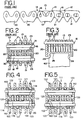
- FIG. 1 shows a prior art rocker joint chain in a side view.
- Rows of inner links 21 in a guide row 12 alternately interleave with rows of inner links 21 in a non-guide row 14 and held by rocker joints comprising pairs of pins 16 and rockers 18.
- a guide link 20 is fixed to the each end of the guide row 12 of inner links 21 by pins 16 which extend outwardly from the rows of inside links.
- FIG. 3 shows an exaggerated cross section through the chain of the prior art and sprocket 40.
- the chain 10 is shown slightly out of position, i.e., raised vertically.
- the limitation in this design is that the contact area between the outermost inside links 22, 23 and sprocket tooth 25 is limited due to the chamfer 26 on the sprocket teeth and the necessary axial clearance between the chain 10 and sprocket 40.
- the partial engagement or partial contact occurs between the outermost inside links 22, 23 of the non-guide row and the sprocket.
- FIG. 14 shows a conventional rocker joint chain with a centered spring link 32.
- Spring links are used in chains conventionally, to help control chain strand vibration by increasing the internal friction in the chain. Compression of the centered spring link 32, in the direction shown by the arrow, forces the links in the rows to press against each other causing friction. The compression of the inside links 21 in the non-guide row 14 against the outside guide links 20 could cause a gap great enough that the rocker pin 18 may become disengaged from the outside guide links 20, forcing the non-guide row 14 of inside links 21 apart, resulting in a loss of chain strength.
- the present invention also has application to silent chains with round connecting pins.
- An example of a round pin silent chain is shown in U.S. Pat. No. 4,758,209, which is incorporated herein by reference.
- the spacing elements especially when they are spring links, help center the inside links between the guide links. This helps provide full engagement of the inside links with the sprocket teeth, helping to distribute the load between the chain and the sprocket more evenly than in a chain without spacing elements. This affect is also beneficial in a rocker joint chain.
- the present invention also has application to chain belts, as shown in U.S. Pat. Nos. 4,580,999 and 5,439,423 which are incorporated herein by reference.
- the plurality of inside links each have a pair of apertures and are interleaved and connected to form rows.
- the plurality of guide links each have a pair of apertures and are placed outside of alternate rows of interleaved inside links to form guide rows. Connecting pins are received in the apertures and extend across the rows of the chain securing the links together.
- Spacing elements are found on opposite side of the chain, specifically between the guide links and the adjacent outermost inside links. The spacing elements act to maintain a spaced relationship between each of the guide links and adjacent outermost inside links. At least one of the spacing elements on one side of the chain is a spring link holding the inside links in compressive frictional contact therebetween.
- the present invention addresses the above-described problems by providing in a power transmission chain, in general terms, a spacing element to ensure that there is full engagement of the rocker and the non-guide row of links to increase the fatigue strength of the chain, while keeping the friction present in the chain at a point such that chain strand resonance is prevented.
- the present invention also allows increased sprocket width providing better contact between the chain and sprocket.
- FIG. 4 shows a sectional view of a preferred embodiment of a rocker joint chain 111 of the present invention.
- the chain is constructed from the assembly of interleaved rows of links.
- Inside links 121 are flanked by guide links 120 and connected by connecting pins, each comprising a pin 116 and a rocker 118.
- the guide links 120 and inside links 121 are shown more clearly in FIG. 6E.
- the inside links shown in FIG. 6E are shown as each having a pair of depending teeth adapted to contact the teeth of an associated sprocket (not shown). It should be understood that other configurations of inner links are contemplated, such as links with a single depending tooth as disclosed in U.S. Pat. No. 5,435,789, incorporated herein by reference.
- the guide links maintain the lateral alignment of the chain on the sprockets.
- the guide links 120 are located along the outside of the chain, i.e., flanking the outermost inside links 122, 123 and do not have teeth for engagement with the sprocket teeth.
- the guide link 120 has projections 160 formed on an inner face. The projections 160 bear upon outermost inside links 122, 123 and act to maintain a space between the main body of the guide links 120 and the inside links 122, 121, 123. Complete bearing contact between the rocker 118 and the outermost inside links 122, 123 at surface 134 is provided by virtue of the slight increase in rocker length allowed by the increased space between the guide links 120 and the outermost inside links 122, 123.
- FIG. 5 An alternate embodiment of the present invention shown in FIG. 4 is illustrated in FIG. 5.
- Projections 162 are formed on the outside face of the outermost inside links 122, 123.
- Each projection 162 serves the same function as projection 160 in FIG. 4, i.e., which is to space apart the inside links 121, 122, 123 from the guide links 120 to provide increased axial clearance. While operating like the embodiment shown in FIG. 4, the present embodiment requires the manufacture of three different link types as opposed to two.
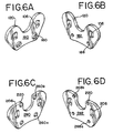
- FIGS. 6A and 6B show an inside and outside view respectively of one embodiment of a guide link of the present invention.
- Guide link 120 has a pair of projections 160 on an inside surface 180 of the link plate.
- the projections 160 are located below the guide link plate apertures 106.
- the corresponding recesses or locations 168 are shown on the outside surface 182 of the guide link 120.
- FIGS. 6C and 6D show an inside and outside view respectively of another embodiment of a guide link of the present invention.
- Guide link 220 has two pair of projections 260a, 260b on an inside surface 280 of the link plate.
- the projections 260a are located below the guide link plate apertures 206, and the projections 260b are located above the guide link plate apertures 206. Note that the top of the guide link has been widened above each aperture to allow space for both the aperture and the projection.
- the corresponding recesses or locations 268a, 268b are shown on the outside surface 282 of the guide link 220.
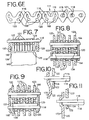
- FIG. 6E shows one embodiment of the location 168 of the projections 160 formed into the guide links 120 shown in FIG. 4 and FIGS. 6A and 6B.
- the projections 160 can be located in any portion of the guide link which allows contact with the outermost inside links 122, 123 and provides the desired axial spacing.
- the projections 160 can be formed by various methods including pressing, stamping, molding, machining or the like.
- Location 168 may also correspond to a recess or dimple formed on the outer face of the guide link 120 when creating the projections on the inner face of the guide link 120 by a stamping process.
- FIG. 7 shows a preferred embodiment of the chain and sprocket in cross section.
- Projections 160 are shown on guide links 120, which bear upon outermost inside links 122, 123.
- the sprocket 140 width can be increased to assure full contact with all the inside links 121 including the outermost inside links 122, 123.
- the additional contact will reduce wear and contact stress between the chain and sprockets, which may in turn allow substitution of lower cost materials or processes for the sprocket, reducing overall system cost.
- FIG. 8 illustrates another embodiment of the present invention.
- a washer 164 encircles the rocker joint between the guide links 120 and the inside links 121.
- the rocker 118 and the outermost inside links 122, 123 are in full contact at surface 134 due to the increased length of the rocker 118 allowed by increased clearance in the axial direction.
- the washer 164 need not be integral with the guide links or the inside links.
- guide links 120 have curved end elements or portions 166 located at each of the distal ends of the guide link 120. Each curved end portion 166 extends inwardly toward the adjacent outermost inside link. The desired axial spacing is maintained by the curved end portions 166 bearing upon the outer face of the outermost inside links 122, 123.
- FIGS. 10 and 11 illustrate in a simplified partial view alternate embodiments of the curved end portions 166 of FIG. 9.
- Curved mid-portions 170, 172 are portions of the guide link 120 which deviate from the typical flat plate-like guide link shape of the prior art.
- the curved mid-portions 170, 172 are located in the midsection of the guide link 120 and serve to maintain a space between the guide link 120 and an adjacent outmost inside link 122.
- An identical curved guide link 120 with a curved mid-portion 170 or 172 would be placed on the opposite side of the chain.
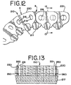
- FIGS. 12 and 13 illustrate a power transmission chain belt 210.
- the chain belt includes links arranged in sets A and B which are interleaved or "laced" with one another.
- a "set” of links are those links which are grouped transversely together; at times a set of links is referred to as a "rank.”
- Each link is provided with a pair of apertures 215, each aperture being adjacent to an end of the link plate, with the apertures in a set being aligned with one another.
- the apertures 215 at one end are transversely aligned with those in the interleaved set, so that the connecting pin interconnects the interlaced links.
- the connecting pin typically includes a rocker 218 and a pin member 216.
- the pin member 216 extends through and is press fit to the apertures of the outermost link plates 220 which are located on the flanks of alternate sets of links.
- the rocker 218 extends through the apertures of the remaining links, at times referred to as the inside links 221, stopping short of the outermost or guide links 220.
- Struts 217 for engaging a pulley transmission are provided to the chain either positioned in a passageway defined by toes which depending from each link or wrapped around the chain. Load blocks (not shown) may be wrapped about the chain to engage a pulley transmission.
- spacing elements or members 260 are applied to inside faces of the guide links 220.
- the benefit of spacing elements as applied to a chain type belt is directed to the increase in contact area between the rocker pin and the outermost inside link aperture.
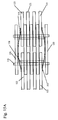
- FIG. 15A shows another alternative embodiment of the present invention in which a pair of separated spring links 332 are used as spacing elements.
- a front and side view of an example of a spring link 332 that may be used in the embodiment are shown in FIGS 17A and 17B.
- the chain is constructed from an assembly of interleaved rows of links. Inside links 121 are flanked by guide links 120 and connected by connecting pins, each comprising a pin 116 and a rocker 118.
- the guide links 120 are located along the outside of the chain, i.e., flanking the outermost inside links 122, 123 and do not have teeth for engagement with the sprocket teeth.
- a pair of spring links 332 are used as spacing elements between the non-guide row 114 of the outermost inside links 122, 123 and the row of outside guide links 120.
- the springs links 332 are arranged such that the ends of the spring links are in contact with the inside links.
- the spacing element provides an increased amount of space, allowing for a longer rocker pin, which will not cause a gap.
- the spacing element is a spring link.
- the inside links 121 in the non-guide rows 114 are not compressed in such a fashion as to allow the rocker pin 118 to become disengaged from the inside links 121.
- the spring links 332 provide a spacing element between the outside guide links 120 and the inner links 121 in non-guide rows 114 and also increases the internal friction in the chain helping to control chain strand vibration.
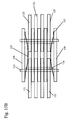
- Figure 15B shows an alternative configuration of the above embodiment.
- the spring links 332 in this configuration perform the same function as in Figure 15A, but are rotated 180°, such that the ends of the spring links are in contact with the guide links.
- FIG. 16 shows another embodiment of the present invention.
- one spring link 400 is placed on one side of the chain between the non-guide row 114 of inside links 121 and the outside guide links 120.
- an outside guide link 120 On the other side of the chain is an outside guide link 120 that has a pair of projections 160 on an inside surface 180 of the link plate 120.
- the projections 160 are located below the guide link plate apertures 106.
- the corresponding recesses or locations 168 are shown on the outside surface 182 of the guide link 120.
- the projections 160 may be located in any portion of the guide link which allows contact with the outermost inside links 122, 123, and provides the desired axial spacing.
- the projections 160 may be formed by various methods including pressing, stamping, molding, machining or the like.
- the combination of the spring link 400 and the projections 160 ensures that the rocker pin 118 protrudes completely through the outermost non-guide row 114 links 122, 123 lending full support to the chain.
- the spacing thus provided between the guide link and the inside links allows the rocker to contact against the entire bearing surface of the aperture of the outermost inside link.
- the spacing provides complete engagement of all the inside links with the entire width of the sprocket. Minimizing the clearance between the rocker and guide link serves to lessen the amount of rocker movement and helps to maintain the stated advantages.
Landscapes
- Engineering & Computer Science (AREA)
- General Engineering & Computer Science (AREA)
- Mechanical Engineering (AREA)
- Devices For Conveying Motion By Means Of Endless Flexible Members (AREA)
- Transmission Devices (AREA)
- Current-Collector Devices For Electrically Propelled Vehicles (AREA)
Abstract
Description
- The invention relates to the field of power transmission chains. More particularly, the invention pertains to a power transmission chain containing spacing elements to increase fatigue strength and decrease incidence of chain strand resonance.
- One aspect of the invention relates to a silent or rocker joint chain, which has links having inverted teeth for engagement with an associated sprocket. Generally, rocker joint chains are used with sprockets for power transmission in transmissions, transfer cases, engine timing systems, and the like. Rocker joint chains are well known in the art. Examples include U.S. Pat. Nos. 5,651,746; 5,345,753; and 5,372,554 which are incorporated herein by reference.
- Rocker joint chains are formed by the assembly of rows of links in lateral and longitudinal directions. Each link typically has a pair of teeth and a pair of pin apertures. The links are interlaced and then connected to each other by connecting pins inserted in each pin aperture. Guide links are utilized as the outermost links of the chain to maintain the chain on the sprockets when the chain is wrapped around the sprockets during operation. Guide links may be installed in the center or at both outer edges of the row of link plates arranged in the lateral direction. The guide links are conventionally press fit over pins, which connect the interlaced inside or articulating links. Guide links typically do not include inverted teeth.
- Conventionally, a rocker joint is used as the connecting pin. The rocker joint is comprised of a pair of long and short pins. A first short pin, referred to as the rocker, is paired with a second longer pin. The longer pin has both ends fixed to guide links at the outmost flanks of the chain.
- Conventional rocker joint chains are limited in the transfer of load between the rocker and the inside links that are positioned at the outermost end of the rocker. The limitation is due to the fact that only partial contact is obtained between these same inside links and the end of the rocker. A separate limitation concerns the contact between the outermost inside links and the sprocket. Due to the required chamfer on sprocket teeth and the axial clearance between the sprocket teeth and chain guide links only partial contact is achieved between the same inside links and the sprocket.
- Prior art rocker joint chains showing the disadvantages in conventional chain designs are shown in FIGS. 1-3 and 14. The chain is comprised of rows of links. Alternate rows of links, or guide rows, have guide links press fit on their ends. The remaining rows, or non-guide rows, have inside links as their outermost links.
- FIG. 1 shows a prior art rocker joint chain in a side view. Rows of
inner links 21 in aguide row 12 alternately interleave with rows ofinner links 21 in anon-guide row 14 and held by rocker joints comprising pairs ofpins 16 androckers 18. Aguide link 20 is fixed to the each end of theguide row 12 ofinner links 21 bypins 16 which extend outwardly from the rows of inside links. - In the prior art rocker
joint chain 10, shown in FIG. 2, there is aclearance 30 between the end of therocker 18 and theguide link 20. Thisclearance 30 exists because of necessary manufacturing tolerances of theindividual rockers 18 so that they are spaced from theguide links 20 after the assembly process. There also exists anend radius 19 on therocker 18, which is necessary to prevent excessive local stresses in thepin 16 androcker 18, and also for ease of assembly of thechain 10. The clearance between therocker 18 and theguide link 20 and the shortening of the rocker as a result of the end radius of the rocker, result in only partial bearing contact between the outermost insidelinks - FIG. 3 shows an exaggerated cross section through the chain of the prior art and sprocket 40. The
chain 10 is shown slightly out of position, i.e., raised vertically. The limitation in this design is that the contact area between theoutermost inside links sprocket tooth 25 is limited due to thechamfer 26 on the sprocket teeth and the necessary axial clearance between thechain 10 and sprocket 40. Thus, the partial engagement or partial contact occurs between the outermost insidelinks - FIG. 14 shows a conventional rocker joint chain with a
centered spring link 32. Spring links are used in chains conventionally, to help control chain strand vibration by increasing the internal friction in the chain. Compression of thecentered spring link 32, in the direction shown by the arrow, forces the links in the rows to press against each other causing friction. The compression of theinside links 21 in thenon-guide row 14 against theoutside guide links 20 could cause a gap great enough that therocker pin 18 may become disengaged from theoutside guide links 20, forcing thenon-guide row 14 ofinside links 21 apart, resulting in a loss of chain strength. - The present invention also has application to silent chains with round connecting pins. An example of a round pin silent chain is shown in U.S. Pat. No. 4,758,209, which is incorporated herein by reference. While there is no rocker in a round pin chain, the spacing elements, especially when they are spring links, help center the inside links between the guide links. This helps provide full engagement of the inside links with the sprocket teeth, helping to distribute the load between the chain and the sprocket more evenly than in a chain without spacing elements. This affect is also beneficial in a rocker joint chain.
- The present invention also has application to chain belts, as shown in U.S. Pat. Nos. 4,580,999 and 5,439,423 which are incorporated herein by reference.
- A chain having a plurality of inside links and guide links. The plurality of inside links each have a pair of apertures and are interleaved and connected to form rows. The plurality of guide links each have a pair of apertures and are placed outside of alternate rows of interleaved inside links to form guide rows. Connecting pins are received in the apertures and extend across the rows of the chain securing the links together. Spacing elements are found on opposite side of the chain, specifically between the guide links and the adjacent outermost inside links. The spacing elements act to maintain a spaced relationship between each of the guide links and adjacent outermost inside links. At least one of the spacing elements on one side of the chain is a spring link holding the inside links in compressive frictional contact therebetween.
-
- FIG. 1 is a longitudinal side view of a portion of a prior art rocker joint chain.
- FIG. 2 is a sectional view of a portion of a prior art rocker joint chain.
- FIG. 3 is a sectional end view illustrating the spacing between the sprocket and guide links in a prior art rocker joint chain.
- FIG. 4 is a sectional view of the power transmission chain of the present invention showing the projections from the guide links.
- FIG. 5 is a sectional view of the power transmission of the present invention showing an alternate location of the projections.
- FIG. 6A is a perspective view of the inside face of the guide link with two projections.
- FIG. 6B is a perspective view of the outside face of the guide link with two projections.
- FIG. 6C is a perspective view of the inside face of the guide link with four projections.
- FIG. 6D is a perspective view of the outside face of the guide link with four projections.
- FIG. 6E is a longitudinal side view of a portion of a power transmission chain of the present invention showing the guide link side opposite the projections.
- FIG. 7 is a sectional end view showing the projections.
- FIG. 8 is a sectional view showing the location of the washers.
- FIG. 9 is a sectional view showing the curved end elements of the guide links.
- FIG. 10 is a partial sectional view showing an embodiment of the curved mid-elements of the guide links.
- FIG. 11 is another embodiment of the curved mid-elements.
- FIG. 12 is a side view of a chain belt.
- FIG. 13 is a sectional view of the chain belt of FIG. 12 with spacing elements. Fig. 1 shows
- FIG. 14 shows top down view of a prior art rocker joint chain with a centered spring link.
- FIG. 15A shows a top down view of another embodiment in which a pair of spring links in one configuration are used as spacing elements.
- FIG. 15B shows a top down view of another embodiment in which a pair of spring links in a different configuration are used as spacing elements than that shown in FIG 15A.
- FIG.16 shows a top down view of an alternative embodiment of the present invention.
- FIG. 17A and 17B show a side view and top view from the chain point of view of an example of a spring link used in the present invention.
-
- The present invention addresses the above-described problems by providing in a power transmission chain, in general terms, a spacing element to ensure that there is full engagement of the rocker and the non-guide row of links to increase the fatigue strength of the chain, while keeping the friction present in the chain at a point such that chain strand resonance is prevented. The present invention also allows increased sprocket width providing better contact between the chain and sprocket. The present invention is explained below with reference to the embodiments illustrated by the attached figures.
- FIG. 4 shows a sectional view of a preferred embodiment of a rocker
joint chain 111 of the present invention. As in the prior art, the chain is constructed from the assembly of interleaved rows of links. Insidelinks 121 are flanked byguide links 120 and connected by connecting pins, each comprising apin 116 and arocker 118. The guide links 120 andinside links 121 are shown more clearly in FIG. 6E. The inside links shown in FIG. 6E are shown as each having a pair of depending teeth adapted to contact the teeth of an associated sprocket (not shown). It should be understood that other configurations of inner links are contemplated, such as links with a single depending tooth as disclosed in U.S. Pat. No. 5,435,789, incorporated herein by reference. - In the chain of the present invention, the guide links maintain the lateral alignment of the chain on the sprockets. The guide links 120 are located along the outside of the chain, i.e., flanking the outermost
inside links guide link 120 hasprojections 160 formed on an inner face. Theprojections 160 bear upon outermostinside links inside links rocker 118 and the outermostinside links surface 134 is provided by virtue of the slight increase in rocker length allowed by the increased space between the guide links 120 and the outermostinside links - An alternate embodiment of the present invention shown in FIG. 4 is illustrated in FIG. 5.
Projections 162 are formed on the outside face of the outermostinside links projection 162 serves the same function asprojection 160 in FIG. 4, i.e., which is to space apart theinside links - FIGS. 6A and 6B show an inside and outside view respectively of one embodiment of a guide link of the present invention.
Guide link 120 has a pair ofprojections 160 on aninside surface 180 of the link plate. Theprojections 160 are located below the guidelink plate apertures 106. The corresponding recesses orlocations 168 are shown on theoutside surface 182 of theguide link 120. - FIGS. 6C and 6D show an inside and outside view respectively of another embodiment of a guide link of the present invention.
Guide link 220 has two pair ofprojections inside surface 280 of the link plate. Theprojections 260a are located below the guidelink plate apertures 206, and theprojections 260b are located above the guidelink plate apertures 206. Note that the top of the guide link has been widened above each aperture to allow space for both the aperture and the projection. The corresponding recesses orlocations outside surface 282 of theguide link 220. - FIG. 6E shows one embodiment of the
location 168 of theprojections 160 formed into the guide links 120 shown in FIG. 4 and FIGS. 6A and 6B. However, theprojections 160 can be located in any portion of the guide link which allows contact with the outermostinside links projections 160 can be formed by various methods including pressing, stamping, molding, machining or the like.Location 168 may also correspond to a recess or dimple formed on the outer face of theguide link 120 when creating the projections on the inner face of theguide link 120 by a stamping process. - FIG. 7 shows a preferred embodiment of the chain and sprocket in cross section.
Projections 160 are shown onguide links 120, which bear upon outermostinside links projections 160, thesprocket 140 width can be increased to assure full contact with all theinside links 121 including the outermostinside links - FIG. 8 illustrates another embodiment of the present invention. A
washer 164 encircles the rocker joint between the guide links 120 and theinside links 121. Therocker 118 and the outermostinside links surface 134 due to the increased length of therocker 118 allowed by increased clearance in the axial direction. Thewasher 164 need not be integral with the guide links or the inside links. - In FIG. 9
guide links 120 have curved end elements orportions 166 located at each of the distal ends of theguide link 120. Eachcurved end portion 166 extends inwardly toward the adjacent outermost inside link. The desired axial spacing is maintained by thecurved end portions 166 bearing upon the outer face of the outermostinside links - FIGS. 10 and 11 illustrate in a simplified partial view alternate embodiments of the
curved end portions 166 of FIG. 9.Curved mid-portions guide link 120 which deviate from the typical flat plate-like guide link shape of the prior art. Thecurved mid-portions guide link 120 and serve to maintain a space between theguide link 120 and an adjacent outmost insidelink 122. An identicalcurved guide link 120 with acurved mid-portion - FIGS. 12 and 13 illustrate a power
transmission chain belt 210. Generally, as shown in FIG. 12, the chain belt includes links arranged in sets A and B which are interleaved or "laced" with one another. A "set" of links are those links which are grouped transversely together; at times a set of links is referred to as a "rank." Each link is provided with a pair ofapertures 215, each aperture being adjacent to an end of the link plate, with the apertures in a set being aligned with one another. When interlaced with other sets of links, theapertures 215 at one end are transversely aligned with those in the interleaved set, so that the connecting pin interconnects the interlaced links. The connecting pin typically includes arocker 218 and apin member 216. Thepin member 216 extends through and is press fit to the apertures of theoutermost link plates 220 which are located on the flanks of alternate sets of links. Therocker 218 extends through the apertures of the remaining links, at times referred to as theinside links 221, stopping short of the outermost or guide links 220.Struts 217 for engaging a pulley transmission (not shown) are provided to the chain either positioned in a passageway defined by toes which depending from each link or wrapped around the chain. Load blocks (not shown) may be wrapped about the chain to engage a pulley transmission. - As shown in FIG. 13, spacing elements or
members 260 are applied to inside faces of the guide links 220. The benefit of spacing elements as applied to a chain type belt is directed to the increase in contact area between the rocker pin and the outermost inside link aperture. - FIG. 15A shows another alternative embodiment of the present invention in which a pair of separated
spring links 332 are used as spacing elements. A front and side view of an example of aspring link 332 that may be used in the embodiment are shown in FIGS 17A and 17B. As in the other embodiments of the present invention, the chain is constructed from an assembly of interleaved rows of links. Insidelinks 121 are flanked byguide links 120 and connected by connecting pins, each comprising apin 116 and arocker 118. The guide links 120 are located along the outside of the chain, i.e., flanking the outermostinside links spring links 332 are used as spacing elements between the non-guide row 114 of the outermostinside links inside links 121 in the non-guide rows 114 are not compressed in such a fashion as to allow therocker pin 118 to become disengaged from theinside links 121. Thus, the spring links 332 provide a spacing element between theoutside guide links 120 and theinner links 121 in non-guide rows 114 and also increases the internal friction in the chain helping to control chain strand vibration. Figure 15B shows an alternative configuration of the above embodiment. The spring links 332 in this configuration perform the same function as in Figure 15A, but are rotated 180°, such that the ends of the spring links are in contact with the guide links. - FIG. 16 shows another embodiment of the present invention. In this embodiment, one spring link 400 is placed on one side of the chain between the non-guide row 114 of
inside links 121 and the outside guide links 120. On the other side of the chain is anoutside guide link 120 that has a pair ofprojections 160 on aninside surface 180 of thelink plate 120. Theprojections 160 are located below the guidelink plate apertures 106. The corresponding recesses orlocations 168 are shown on theoutside surface 182 of theguide link 120. However, theprojections 160 may be located in any portion of the guide link which allows contact with the outermostinside links projections 160 may be formed by various methods including pressing, stamping, molding, machining or the like. The combination of the spring link 400 and theprojections 160 ensures that therocker pin 118 protrudes completely through the outermost non-guide row 114links - The spacing thus provided between the guide link and the inside links allows the rocker to contact against the entire bearing surface of the aperture of the outermost inside link. In addition, the spacing provides complete engagement of all the inside links with the entire width of the sprocket. Minimizing the clearance between the rocker and guide link serves to lessen the amount of rocker movement and helps to maintain the stated advantages.
- Those skilled in the art to which the invention pertains may make modifications and other embodiments employing the principles of this invention without departing from its spirit or essential characteristics particularly upon considering the foregoing teachings. The described embodiments are to be considered in all respects only as illustrative and not restrictive and the scope of the invention is, therefore, indicated by the appended claims rather than by the foregoing description. Consequently, while the invention has been described with reference to particular embodiments, modifications of structure, sequence, materials and the like would be apparent to those skilled in the art, yet still fall within the scope of the invention.
Claims (9)
- An improved power transmission chain of the type in which a plurality of interleaved inside links, each of the inside links having a pair of apertures, the inside links being interleaved and connected into a series of rows, a plurality of guide links, each of the guide links having a pair of apertures, the guide links being placed outside of alternate rows of interleaved inside links to form guide rows, and connecting pins received in the apertures, the connecting pins extending across the rows of the chain and having ends secured within the apertures of the guide links, thereby connecting the inside link and the guide links, wherein the improvement comprises:spacing elements on opposite sides of the chain, located between the guide links and an adjacent outermost inside link, the spacing elements acting to maintain a spaced relationship between each guide link and outermost adjacent inside links;at least one of the spacing elements being a spring link for holding the inside links in compressive frictional contact therebetween.
- The improved power transmission chain of claim 1, wherein the spacing elements on both opposite sides of the chain are spring links.
- The improved power transmission chain of claim 1, wherein one of the spacing elements is a spring link and the spacing element on the opposite side of the chain is washer.
- The improved power transmission chain of claim 1, wherein one of the spacing elements is a spring link and the spacing element on the opposite side of the chain are a plurality of protruding members formed on an outer face of the adjacent outermost inside link projecting toward the guide links.
- The improved power transmission chain of claim 1, wherein one of the spacing elements is a spring link and the spacing element on the opposite side of the chain are a plurality of protruding members formed on an inner face of the guide links projecting toward the adjacent outermost inside links.
- The improved power transmission chain of claim 1, wherein one of the spacing elements is a spring link and the spacing element on the opposite side of the chain are curved mid-portions of the guide links.
- The improved power transmission chain of claim 1, wherein the spacing elements maintain a space between the guide links and the outermost inside links.
- The improved power transmission chain of claim 1, wherein the connecting pins further comprise a first rocker pin and a second pin, the second pin being press fit into the apertures of the guide links.
- The improved power transmission chain of claim 8, wherein the second pin is round.
Applications Claiming Priority (2)
| Application Number | Priority Date | Filing Date | Title |
|---|---|---|---|
| US10/447,787 US7048665B2 (en) | 1999-04-28 | 2003-05-29 | Power transmission chain having links with lateral spacing elements |
| US447787 | 2003-05-29 |
Publications (3)
| Publication Number | Publication Date |
|---|---|
| EP1482206A2 true EP1482206A2 (en) | 2004-12-01 |
| EP1482206A3 EP1482206A3 (en) | 2005-06-15 |
| EP1482206B1 EP1482206B1 (en) | 2013-09-25 |
Family
ID=33131595
Family Applications (1)
| Application Number | Title | Priority Date | Filing Date |
|---|---|---|---|
| EP04252774.7A Expired - Lifetime EP1482206B1 (en) | 2003-05-29 | 2004-05-13 | Power transmission chain having links with lateral spacing elements |
Country Status (5)
| Country | Link |
|---|---|
| US (1) | US7048665B2 (en) |
| EP (1) | EP1482206B1 (en) |
| JP (1) | JP4530710B2 (en) |
| KR (1) | KR101074639B1 (en) |
| CN (1) | CN100453844C (en) |
Cited By (2)
| Publication number | Priority date | Publication date | Assignee | Title |
|---|---|---|---|---|
| GB2430477A (en) * | 2005-09-27 | 2007-03-28 | Tsubakimoto Chain Co | Silent chain with guide plates having protrusions that exert a spring action on the link plates |
| EP1840408A2 (en) | 2006-03-30 | 2007-10-03 | JTEKT Corporation | Power transmission chain, and power transmission system having the same |
Families Citing this family (24)
| Publication number | Priority date | Publication date | Assignee | Title |
|---|---|---|---|---|
| JP4409899B2 (en) * | 2003-09-26 | 2010-02-03 | ボルグワーナー・モールステック・ジャパン株式会社 | Silent chain |
| US20050130779A1 (en) * | 2003-12-10 | 2005-06-16 | Borgwarner Morse Tec Japan K.K. | Chain with a mark |
| CN101283196B (en) * | 2005-10-06 | 2011-09-21 | 卢克摩擦片和离合器两合公司 | Link plate, chain comprising said link plate, the thus obtained chain drive and a motor vehicle provided therewith |
| US20070087882A1 (en) * | 2005-10-06 | 2007-04-19 | Luk Lamellen Und Kupplungsbau Beteiligungs Kg | Link plate for a plate-link chain |
| US20080132369A1 (en) * | 2006-12-01 | 2008-06-05 | General Motors Corporation | Longitudinal Spring Damper for Damping Chain Vibration |
| JP2008256186A (en) * | 2007-04-09 | 2008-10-23 | Tsubakimoto Chain Co | Silent chain |
| JP2009144742A (en) * | 2007-12-11 | 2009-07-02 | Tsubakimoto Chain Co | Silent chain |
| JP5522965B2 (en) | 2009-04-03 | 2014-06-18 | ボーグワーナー インコーポレーテッド | chain |
| JP5094806B2 (en) * | 2009-09-17 | 2012-12-12 | 株式会社椿本チエイン | Silent chain |
| DE102011005190A1 (en) * | 2010-03-18 | 2012-05-10 | Schaeffler Technologies Gmbh & Co. Kg | Double-sided tooth chain |
| JP2012067799A (en) * | 2010-09-21 | 2012-04-05 | Tsubakimoto Chain Co | Guide plate |
| JP5766140B2 (en) * | 2012-03-13 | 2015-08-19 | 株式会社椿本チエイン | Chain transmission |
| JP5611262B2 (en) * | 2012-03-30 | 2014-10-22 | 株式会社椿本チエイン | Silent chain |
| USD734590S1 (en) * | 2012-07-24 | 2015-07-14 | Nordischer Maschinenbau Rud. Baader Gmbh + Co. Kg | Chain link |
| USD731569S1 (en) | 2012-07-24 | 2015-06-09 | Nordischer Maschinenbau Rud. Baader Gmbh + Co. Kg | Sprocket for chain link |
| DE102012106708A1 (en) | 2012-07-24 | 2014-10-30 | Nordischer Maschinenbau Rud. Baader Gmbh + Co. Kg | Chain link, support chain and support device |
| JP5839400B2 (en) * | 2012-08-08 | 2016-01-06 | 株式会社椿本チエイン | Silent chain |
| JP2016038005A (en) * | 2014-08-06 | 2016-03-22 | 株式会社椿本チエイン | Silent chain transmission device |
| JP6423689B2 (en) * | 2014-11-14 | 2018-11-14 | 株式会社椿本チエイン | Silent chain |
| JP6802482B2 (en) * | 2017-02-06 | 2020-12-16 | 株式会社椿本チエイン | Chain and chain transmission |
| JP6802483B2 (en) * | 2017-02-06 | 2020-12-16 | 株式会社椿本チエイン | Chain and chain transmission |
| DE102018113750A1 (en) * | 2018-06-08 | 2019-12-12 | Schaeffler Technologies AG & Co. KG | link chain |
| US10830309B2 (en) * | 2018-06-27 | 2020-11-10 | Borgwarner Inc. | Chain drive system having anti-rotation features between pivot pin and guide link and related assembly method |
| CN116197345B (en) * | 2022-12-29 | 2025-09-19 | 杭州东华链条集团有限公司 | Assembly equipment and assembly method for plate-type chain |
Citations (7)
| Publication number | Priority date | Publication date | Assignee | Title |
|---|---|---|---|---|
| US4580999A (en) | 1984-11-29 | 1986-04-08 | Borg-Warner Corporation | Metal chain-belt |
| US4758209A (en) | 1987-04-01 | 1988-07-19 | Borg-Warner Automotive, Inc. | Silent timing chain and sprocket system |
| US5345753A (en) | 1993-07-28 | 1994-09-13 | Borg-Warner Automotive, K.K. | Silent chain |
| US5372554A (en) | 1992-08-31 | 1994-12-13 | Borg-Warner Automotive K.K. | Rocker joint chain with crescent shaped apertures |
| US5435789A (en) | 1994-08-10 | 1995-07-25 | Borg-Warner Automotive, Inc. | Inverted tooth chain constructed with links having a single toe |
| US5439423A (en) | 1993-04-09 | 1995-08-08 | Borg-Warner Automotive, Inc. | Chain belt where load block has grooves for engagement with protrusions on link plates |
| US5651746A (en) | 1994-08-29 | 1997-07-29 | Borg-Warner Automotive, K.K. | Power transmission chain |
Family Cites Families (28)
| Publication number | Priority date | Publication date | Assignee | Title |
|---|---|---|---|---|
| US1004389A (en) * | 1911-05-09 | 1911-09-26 | Link Belt Co | Chain. |
| US1352017A (en) * | 1917-09-08 | 1920-09-07 | Morse Chain Co | Multiplate drive-chain |
| US1704279A (en) * | 1924-04-21 | 1929-03-05 | Chrysler Corp | Drive chain |
| US1727129A (en) * | 1926-01-26 | 1929-09-03 | Morse Chain Co | Multiplate drive chain |
| US3068712A (en) | 1960-01-15 | 1962-12-18 | Sedis Transmissions Mec | Transmission chain |
| FR1344486A (en) | 1962-10-19 | 1963-11-29 | Improvements to chains, especially for carriers | |
| US3620094A (en) | 1969-02-18 | 1971-11-16 | Ilya Ilich Ivashkov | Flat-link chain |
| US3877688A (en) * | 1973-11-23 | 1975-04-15 | Borg Warner | Spring clip for sprocket or roller chain |
| US4094515A (en) | 1976-02-20 | 1978-06-13 | Kumakichi Araya | Seal device in a roller chain |
| JPS581304B2 (en) | 1979-04-09 | 1983-01-11 | トヨタ自動車株式会社 | chain transmission device |
| US4494945A (en) | 1982-01-29 | 1985-01-22 | Enuma Chain Manufacturing Co., Ltd. | Roller chain link construction and method of manufacture |
| US4943266A (en) | 1984-11-29 | 1990-07-24 | Borg-Warner Corporation | Metal chain belt |
| JPS61165048A (en) * | 1985-01-14 | 1986-07-25 | Borg Warner Ootomooteibu Kk | Silent chain |
| JPS62110045A (en) | 1985-11-06 | 1987-05-21 | Nissan Motor Co Ltd | Friction transmission chain |
| US4911682A (en) | 1987-10-28 | 1990-03-27 | Borg-Warner Automotive, Inc. | Cambered pin CVT chain belt |
| US5061226A (en) | 1990-03-20 | 1991-10-29 | Borg-Warner Automotive Transmission & Engine Components Corporation | Chain-belt |
| US5114384A (en) | 1990-03-28 | 1992-05-19 | Tsubakimoto Chain Co. | Silent drive chain |
| JP2510671Y2 (en) | 1990-11-08 | 1996-09-18 | 株式会社椿本チエイン | Silent chain |
| US5327554A (en) * | 1990-11-29 | 1994-07-05 | Palazzi Iii Michael A | Interactive terminal for the access of remote database information |
| GB2252387A (en) | 1991-02-01 | 1992-08-05 | Chia Long Wu | An improved chain particularly for a bicycle |
| US5192252A (en) | 1991-10-16 | 1993-03-09 | Borg-Warner Automotive Transmission & Engine Components Corporation | Roller chain with randomized pitch |
| US5318485A (en) | 1992-09-24 | 1994-06-07 | Borg-Warner Automotive, Inc. | Chain-belt |
| US5409424A (en) | 1993-04-09 | 1995-04-25 | Borg-Warner Automotive, Inc. | Chain belt with two parallel chains having means for inhibiting relative movements of the chains |
| US5445570A (en) | 1994-02-15 | 1995-08-29 | Borg-Warner Automotive, Inc. | Chain guide link |
| JPH0874939A (en) | 1994-09-02 | 1996-03-19 | Borg Warner Automot Kk | Power transmitting chain |
| JP2000130518A (en) * | 1998-10-22 | 2000-05-12 | Borg Warner Automotive Kk | Silent chain |
| US6406394B1 (en) * | 1999-04-28 | 2002-06-18 | Borgwarner Inc. | Power transmission chain having links with lateral spacing elements |
| JP3091456B1 (en) | 1999-08-02 | 2000-09-25 | 株式会社椿本チエイン | Wear-resistant silent chain |
-
2003
- 2003-05-29 US US10/447,787 patent/US7048665B2/en not_active Expired - Lifetime
-
2004
- 2004-04-26 JP JP2004129400A patent/JP4530710B2/en not_active Expired - Fee Related
- 2004-05-13 EP EP04252774.7A patent/EP1482206B1/en not_active Expired - Lifetime
- 2004-05-24 KR KR1020040036750A patent/KR101074639B1/en not_active Expired - Fee Related
- 2004-05-28 CN CNB2004100459822A patent/CN100453844C/en not_active Expired - Fee Related
Patent Citations (8)
| Publication number | Priority date | Publication date | Assignee | Title |
|---|---|---|---|---|
| US4580999A (en) | 1984-11-29 | 1986-04-08 | Borg-Warner Corporation | Metal chain-belt |
| US4758209A (en) | 1987-04-01 | 1988-07-19 | Borg-Warner Automotive, Inc. | Silent timing chain and sprocket system |
| US5372554A (en) | 1992-08-31 | 1994-12-13 | Borg-Warner Automotive K.K. | Rocker joint chain with crescent shaped apertures |
| US5439423A (en) | 1993-04-09 | 1995-08-08 | Borg-Warner Automotive, Inc. | Chain belt where load block has grooves for engagement with protrusions on link plates |
| US5345753A (en) | 1993-07-28 | 1994-09-13 | Borg-Warner Automotive, K.K. | Silent chain |
| US5435789A (en) | 1994-08-10 | 1995-07-25 | Borg-Warner Automotive, Inc. | Inverted tooth chain constructed with links having a single toe |
| US5651746A (en) | 1994-08-29 | 1997-07-29 | Borg-Warner Automotive, K.K. | Power transmission chain |
| US5651746B1 (en) | 1994-08-29 | 2000-01-04 | Borg Warner Automotive Kk | Power transmission chain |
Cited By (6)
| Publication number | Priority date | Publication date | Assignee | Title |
|---|---|---|---|---|
| GB2430477A (en) * | 2005-09-27 | 2007-03-28 | Tsubakimoto Chain Co | Silent chain with guide plates having protrusions that exert a spring action on the link plates |
| US7329198B2 (en) | 2005-09-27 | 2008-02-12 | Tsubakimoto Chain Co. | Silent chain |
| GB2430477B (en) * | 2005-09-27 | 2010-10-06 | Tsubakimoto Chain Co | Silent chain |
| EP1840408A2 (en) | 2006-03-30 | 2007-10-03 | JTEKT Corporation | Power transmission chain, and power transmission system having the same |
| US8038561B2 (en) | 2006-03-30 | 2011-10-18 | Jtekt Corporation | Power transmission chain, and power transmission system having the same |
| EP1840408B1 (en) * | 2006-03-30 | 2013-12-11 | JTEKT Corporation | Power transmission chain, and power transmission system having the same |
Also Published As
| Publication number | Publication date |
|---|---|
| EP1482206B1 (en) | 2013-09-25 |
| KR101074639B1 (en) | 2011-10-19 |
| US7048665B2 (en) | 2006-05-23 |
| CN100453844C (en) | 2009-01-21 |
| US20030236145A1 (en) | 2003-12-25 |
| KR20040103772A (en) | 2004-12-09 |
| CN1573163A (en) | 2005-02-02 |
| JP4530710B2 (en) | 2010-08-25 |
| JP2004353865A (en) | 2004-12-16 |
| EP1482206A3 (en) | 2005-06-15 |
Similar Documents
| Publication | Publication Date | Title |
|---|---|---|
| US7048665B2 (en) | Power transmission chain having links with lateral spacing elements | |
| US6406394B1 (en) | Power transmission chain having links with lateral spacing elements | |
| US5372554A (en) | Rocker joint chain with crescent shaped apertures | |
| US5758484A (en) | Silent chain with raised link backs | |
| US5464374A (en) | Chain having improved load distribution | |
| US4911682A (en) | Cambered pin CVT chain belt | |
| US6733410B2 (en) | Wear-elongation resistant silent chain | |
| US6575863B2 (en) | Inwardly cambered rocker joint for a power transmission chain | |
| JPH0553978B2 (en) | ||
| US8998758B2 (en) | Chain | |
| US5267909A (en) | Power transmission chain constructed with butt style links | |
| US6186921B1 (en) | Rocker joint silent chain having a joint pin thicker than a corresponding rocker pin | |
| US20060105872A1 (en) | Silent chain | |
| US5562559A (en) | Rocker joint chain with crescent shaped aperture | |
| US20100120568A1 (en) | Silent chain with bushings | |
| CA1303875C (en) | Cambered pin cvt chain belt | |
| US20090186730A1 (en) | Silent chain | |
| US7329198B2 (en) | Silent chain | |
| US4822323A (en) | Endless transmission belt | |
| EP0945645A1 (en) | Three-way phased continuously variable transmission chain with strut retention | |
| JPS61236946A (en) | Endless belt for transmission | |
| JPH0768998B2 (en) | Transmission belt | |
| JPS63149450A (en) | V shaped chain belt for power transmission |
Legal Events
| Date | Code | Title | Description |
|---|---|---|---|
| PUAI | Public reference made under article 153(3) epc to a published international application that has entered the european phase |
Free format text: ORIGINAL CODE: 0009012 |
|
| AK | Designated contracting states |
Kind code of ref document: A2 Designated state(s): AT BE BG CH CY CZ DE DK EE ES FI FR GB GR HU IE IT LI LU MC NL PL PT RO SE SI SK TR |
|
| AX | Request for extension of the european patent |
Extension state: AL HR LT LV MK |
|
| PUAL | Search report despatched |
Free format text: ORIGINAL CODE: 0009013 |
|
| RAP1 | Party data changed (applicant data changed or rights of an application transferred) |
Owner name: BORGWARNER INC. |
|
| AK | Designated contracting states |
Kind code of ref document: A3 Designated state(s): AT BE BG CH CY CZ DE DK EE ES FI FR GB GR HU IE IT LI LU MC NL PL PT RO SE SI SK TR |
|
| AX | Request for extension of the european patent |
Extension state: AL HR LT LV MK |
|
| RIC1 | Information provided on ipc code assigned before grant |
Ipc: 7F 16G 13/04 B Ipc: 7F 16G 13/02 A Ipc: 7F 16G 5/18 B |
|
| 17P | Request for examination filed |
Effective date: 20050728 |
|
| AKX | Designation fees paid |
Designated state(s): DE FR IT |
|
| 17Q | First examination report despatched |
Effective date: 20100429 |
|
| GRAP | Despatch of communication of intention to grant a patent |
Free format text: ORIGINAL CODE: EPIDOSNIGR1 |
|
| INTG | Intention to grant announced |
Effective date: 20130418 |
|
| GRAS | Grant fee paid |
Free format text: ORIGINAL CODE: EPIDOSNIGR3 |
|
| GRAP | Despatch of communication of intention to grant a patent |
Free format text: ORIGINAL CODE: EPIDOSNIGR1 |
|
| GRAA | (expected) grant |
Free format text: ORIGINAL CODE: 0009210 |
|
| INTG | Intention to grant announced |
Effective date: 20130809 |
|
| AK | Designated contracting states |
Kind code of ref document: B1 Designated state(s): DE FR IT |
|
| REG | Reference to a national code |
Ref country code: DE Ref legal event code: R096 Ref document number: 602004043405 Country of ref document: DE Effective date: 20131121 |
|
| REG | Reference to a national code |
Ref country code: DE Ref legal event code: R097 Ref document number: 602004043405 Country of ref document: DE |
|
| PLBE | No opposition filed within time limit |
Free format text: ORIGINAL CODE: 0009261 |
|
| STAA | Information on the status of an ep patent application or granted ep patent |
Free format text: STATUS: NO OPPOSITION FILED WITHIN TIME LIMIT |
|
| 26N | No opposition filed |
Effective date: 20140626 |
|
| REG | Reference to a national code |
Ref country code: DE Ref legal event code: R097 Ref document number: 602004043405 Country of ref document: DE Effective date: 20140626 |
|
| REG | Reference to a national code |
Ref country code: FR Ref legal event code: PLFP Year of fee payment: 13 |
|
| REG | Reference to a national code |
Ref country code: FR Ref legal event code: PLFP Year of fee payment: 14 |
|
| REG | Reference to a national code |
Ref country code: FR Ref legal event code: PLFP Year of fee payment: 15 |
|
| PGFP | Annual fee paid to national office [announced via postgrant information from national office to epo] |
Ref country code: ES Payment date: 20190619 Year of fee payment: 9 |
|
| PGFP | Annual fee paid to national office [announced via postgrant information from national office to epo] |
Ref country code: FR Payment date: 20190417 Year of fee payment: 16 |
|
| PG25 | Lapsed in a contracting state [announced via postgrant information from national office to epo] |
Ref country code: FR Free format text: LAPSE BECAUSE OF NON-PAYMENT OF DUE FEES Effective date: 20200531 |
|
| PG25 | Lapsed in a contracting state [announced via postgrant information from national office to epo] |
Ref country code: IT Free format text: LAPSE BECAUSE OF NON-PAYMENT OF DUE FEES Effective date: 20200513 |
|
| PGFP | Annual fee paid to national office [announced via postgrant information from national office to epo] |
Ref country code: DE Payment date: 20220411 Year of fee payment: 19 |
|
| P01 | Opt-out of the competence of the unified patent court (upc) registered |
Effective date: 20230327 |
|
| REG | Reference to a national code |
Ref country code: DE Ref legal event code: R119 Ref document number: 602004043405 Country of ref document: DE |
|
| PG25 | Lapsed in a contracting state [announced via postgrant information from national office to epo] |
Ref country code: DE Free format text: LAPSE BECAUSE OF NON-PAYMENT OF DUE FEES Effective date: 20231201 |