EP1482167A1 - Valve needle, metering device, and method of calibrating a metering device - Google Patents
Valve needle, metering device, and method of calibrating a metering device Download PDFInfo
- Publication number
- EP1482167A1 EP1482167A1 EP03012437A EP03012437A EP1482167A1 EP 1482167 A1 EP1482167 A1 EP 1482167A1 EP 03012437 A EP03012437 A EP 03012437A EP 03012437 A EP03012437 A EP 03012437A EP 1482167 A1 EP1482167 A1 EP 1482167A1
- Authority
- EP
- European Patent Office
- Prior art keywords
- valve needle
- calibration means
- calibration
- fluid
- opening
- Prior art date
- Legal status (The legal status is an assumption and is not a legal conclusion. Google has not performed a legal analysis and makes no representation as to the accuracy of the status listed.)
- Granted
Links
Images


Classifications
-
- F—MECHANICAL ENGINEERING; LIGHTING; HEATING; WEAPONS; BLASTING
- F02—COMBUSTION ENGINES; HOT-GAS OR COMBUSTION-PRODUCT ENGINE PLANTS
- F02M—SUPPLYING COMBUSTION ENGINES IN GENERAL WITH COMBUSTIBLE MIXTURES OR CONSTITUENTS THEREOF
- F02M61/00—Fuel-injectors not provided for in groups F02M39/00 - F02M57/00 or F02M67/00
- F02M61/04—Fuel-injectors not provided for in groups F02M39/00 - F02M57/00 or F02M67/00 having valves, e.g. having a plurality of valves in series
- F02M61/042—The valves being provided with fuel passages
-
- F—MECHANICAL ENGINEERING; LIGHTING; HEATING; WEAPONS; BLASTING
- F02—COMBUSTION ENGINES; HOT-GAS OR COMBUSTION-PRODUCT ENGINE PLANTS
- F02M—SUPPLYING COMBUSTION ENGINES IN GENERAL WITH COMBUSTIBLE MIXTURES OR CONSTITUENTS THEREOF
- F02M61/00—Fuel-injectors not provided for in groups F02M39/00 - F02M57/00 or F02M67/00
- F02M61/04—Fuel-injectors not provided for in groups F02M39/00 - F02M57/00 or F02M67/00 having valves, e.g. having a plurality of valves in series
- F02M61/08—Fuel-injectors not provided for in groups F02M39/00 - F02M57/00 or F02M67/00 having valves, e.g. having a plurality of valves in series the valves opening in direction of fuel flow
-
- F—MECHANICAL ENGINEERING; LIGHTING; HEATING; WEAPONS; BLASTING
- F02—COMBUSTION ENGINES; HOT-GAS OR COMBUSTION-PRODUCT ENGINE PLANTS
- F02M—SUPPLYING COMBUSTION ENGINES IN GENERAL WITH COMBUSTIBLE MIXTURES OR CONSTITUENTS THEREOF
- F02M61/00—Fuel-injectors not provided for in groups F02M39/00 - F02M57/00 or F02M67/00
- F02M61/04—Fuel-injectors not provided for in groups F02M39/00 - F02M57/00 or F02M67/00 having valves, e.g. having a plurality of valves in series
- F02M61/10—Other injectors with elongated valve bodies, i.e. of needle-valve type
- F02M61/12—Other injectors with elongated valve bodies, i.e. of needle-valve type characterised by the provision of guiding or centring means for valve bodies
-
- F—MECHANICAL ENGINEERING; LIGHTING; HEATING; WEAPONS; BLASTING
- F02—COMBUSTION ENGINES; HOT-GAS OR COMBUSTION-PRODUCT ENGINE PLANTS
- F02M—SUPPLYING COMBUSTION ENGINES IN GENERAL WITH COMBUSTIBLE MIXTURES OR CONSTITUENTS THEREOF
- F02M61/00—Fuel-injectors not provided for in groups F02M39/00 - F02M57/00 or F02M67/00
- F02M61/16—Details not provided for in, or of interest apart from, the apparatus of groups F02M61/02 - F02M61/14
- F02M61/168—Assembling; Disassembling; Manufacturing; Adjusting
Definitions
- the present invention relates to a valve needle for a high-pressure fuel injector, in which axial movement of the valve needle in a valve cartridge controls opening and closing of a metering opening of the injector for dosing a fluid, comprising a valve needle body section that is formed for providing a fluid passage from an upstream portion of the valve needle to a downstream portion of the valve needle.
- the present invention further relates to a combination of a valve needle and a calibration means.
- the present invention still further relates to a metering device for dosing pressurized fluids, particularly an injection valve for a fuel injection system in an internal combustion engine.
- the present invention further relates to a method of calibrating and metering device.
- Prior art valve needles for use in high-pressure direct injection gasoline engines provide a fluid passage between the valve needle and the valve cartridge, as can be seen for example in EP 1 046 809 A2.
- Another aspect related to high-pressure direct injection valves concerns calibration of these valves.
- the injector calibration operation is usually performed by adjusting the position of a thermal compensator or by changing a preload of the valve spring.
- the present invention improves the valve needle according to prior art in that at least a part of the valve needle body section is hollow so that a fluid passage through the valve needle is provided, the valve needle body section provides at least one fluid entrance opening in the upstream portion of the valve needle for fluid entering the fluid passage through the valve needle and at least one fluid exit opening in the downstream portion of the valve needle for fluid leaving the fluid passage through the valve needle, and an axially extending opening in the downstream portion of the valve needle into which a calibration means can be inserted, the calibration means sealing the axially extending opening and influencing the fluid passage through the valve needle in dependence of an insertion depth of the calibration means.
- the fluid to be dosed can be transported through the hollow valve needle body section, there are no more restrictions with respect to the guiding of the valve needle by providing a close sliding fit to the cartridge. Furthermore, since the calibration means are inserted into an axially extending opening that is accessible in a completely assembled state of the injector, a convenient calibration process can be performed.
- the calibration means comprises a calibration pin with sealing means for sealing the axially extending opening.
- the pin can be inserted in different depths into the axially extending opening, so that the influence on the flow passage can be adjusted.
- a sealing means is provided in order to seal the axially extending opening during the calibration process so that no fluid can leave the hollow valve needle body section through the axially extending opening.
- the sealing means can also contribute to the sealing of the axially extending opening after calibration, i. e. in the completely assembled state of the injector.
- the calibration means comprises a calibration screw with sealing means for sealing the axially extending opening.
- the sealing means comprises an o-ring sitting on the calibration means.
- An o-ring is a commercially available component which ensures sufficient sealing, in particular during the calibration process.
- the calibration means can be welded to the valve needle. Due to this welding, a precise insertion depth of the calibration means into the axially extending hole is conserved. Further, the welding can seal the axially extending opening hermetically.
- the calibration means influences a free flow path through the at least one fluid exit opening in the downstream portion of the valve needle.
- the flow passage through the valve needle is only influenced in the exit region, which is sufficient in order to calibrate the amount of fluid leaving through the at least one fluid exit opening.
- the valve needle comprises at least one cylindrical section as a valve needle guide inside the cartridge.
- Prior art valve needles are provided with guiding elements that build only part of the outer surface of the guiding length of the valve needle, since the rest of the outer surface has to be in a certain distance to the cartridge in order to provide a flow passage.
- a further valve needle body section is provided that is solid and mounted to an upstream end of the hollow valve needle body section.
- the part of the valve needle that is not needed for fluid passage purposes is realized in a solid manner as according to prior art.
- the at least one fluid entrance opening and/or the at least one fluid exit opening comprise one or more holes and/or slots.
- Such holes and slots are easy to manufacture, and the fluid path through an axially extending slot in the wall of the hollow needle can be ideally influenced by a longitudinal calibration means, e. g. a pin or a screw.
- the present invention is further realized by a combination of a valve needle according to the present invention and a calibration means that can be inserted into an axially extending opening in the downstream portion of the valve needle, the calibration means sealing the axially extending opening and influencing the fluid passage through the valve needle in dependence of an insertion depth of the calibration means.
- a combination of a valve needle and calibration means exhibits the same advantages and particularities as stated above in connection with the valve needle according to the present invention. This also applies to the preferred embodiments of the combination as stated below.
- the combination is favorable in that the calibration means comprises a calibration pin with sealing means for sealing the axially extending opening.
- the combination is particularly advantageous in that the calibration means comprises a calibration screw with sealing means for sealing the axially extending opening.
- the sealing means comprises an o-ring sitting on the calibration means.
- the calibration means can be welded to the valve needle.
- the combination of the valve needle and the calibration means is particularly advantageous in that the calibration means influences a free flow path through the at least one fluid exit opening in the downstream portion of the valve needle.
- the present invention is realized by a metering device for dosing pressurized fluids, particularly an injection valve for a fuel injection system in an internal combustion engine, comprising a valve cartridge, and the combination of a valve needle and a calibration means according to the present invention.
- a metering device is provided that is advantageous due to the improvements and particularities of the valve needle according to the present invention and the combination of a valve needle and a calibration means according to the present invention.
- Another aspect of the present invention is a method of calibrating a metering device according to the present invention, the method comprising the steps of inserting the calibration means into the axially extending opening in the downstream portion of the valve needle, observing the amount of fluid that is ejected by the injection valve, when the metering opening is opened, adjusting the insertion depth of the calibration means until a desired amount of fluid is ejected, when the metering opening is opened, and fastening the calibration means to the valve needle. Due to this calibration method the injector can be completely and finally mounted before calibration. Only the calibration means has to be inserted and no further changes to the injector set up are necessary in order to ensure a correct calibration.
- fastening the calibration means to the valve needle comprises welding. Thereby a hermetically sealing of the axially extending opening in the valve needle is achieved.
- the present invention provides a solution by which a new guiding concept of the valve needle inside the cartridge is realized and that allows a very precise and convenient calibration process.
- the tubular valve needle is less expensive than valve needles according to prior art, and the valve needle can be shorter than before.
- the injector can be flushed through the axially extending opening so that the seat zone of the valve needle has not to be used for flushing.
- the hollow valve needle body section provides the possibility to insert a screen filter inside the needle and/or to insert an anti-bounce device inside the needle. As an additional effect, the fluid path inside the needle provides a cooling, so that the thermal expansion of the needle is reduced.
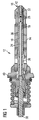
- FIG. 1 is a cross sectional view of a metering device according to the present invention.
- the injection valve 12 comprises of a valve cartridge 14 that is mounted to a valve body 40. Inside the cartridge 14 and the valve body 40, a valve needle 10 is arranged.
- the valve needle 10 ends with a plunger 42 for closing and opening a metering opening 16.
- a valve needle body section 18 is hollow so that a fluid passage 24 is provided inside the valve needle 10. Fluid entrance openings 26 allow fluid to enter into the fluid passage 24, and fluid exit openings 28 allow fluid to leave the fluid passage 24.
- the valve needle 10 comprises of an axially extending opening 30 (cf. Figure 3) that is located at the plunger end of the valve needle 10.
- the valve needle 10 comprises a cylindrical section 36 providing a close sliding fit of the valve needle 10 in the cartridge 14. It is possible to provide this cylindrical section 36, because the fluid passage 24 is inside in the valve needle 10 and not between the valve needle 10 and the cartridge 14.
- the valve needle 10 further comprises a solid valve needle body section 38 that is mounted to an upstream portion of the hollow valve needle body section 18.
- Figure 2 is an exploded side elevational view of a valve needle according to the present invention and Figure 3 is a cross sectional view of a valve needle according to the present invention and of a calibration means used in a combination of a valve needle and a calibration means according to the present invention.
- Figure 2 illustrates how the fluid entrance openings 26 and the fluid exit openings 28 are provided.
- the fluid entrance openings 26 are provided as elongated slots in an upstream portion 20 of the valve needle 10.
- the fluid exit openings 28 are provided as elongated slots in a downstream portion 22 of the valve needle 10.
- the calibration pin 32 comprises of several sections with different diameters, thereby providing the possibility of pulling an o-ring 34 over the calibration pin 32. This o-ring 34 seals the fluid passage 24 at least during the calibration procedure.
- FIG 4 is a cross sectional view of a combination of a valve needle and a calibration means according to the present invention.
- the valve needle 10 is shown in a similar manner as in Figure 1 without the further injector components.
- FIG. 5 is a flow chart illustrating a preferred embodiment of a calibration method according to the present invention.
- a hollow valve needle 10 that provides a fluid passage 24 is provided for an injection valve 12.
- the valve needle 10 comprises fluid entrance openings 26 and fluid exit openings 28. Between these openings 26, 28 a cylindrical section 36 is located for providing a close sliding fit of the valve needle in the valve cartridge 14.
- a calibration means 32 e. g. a pin or a screw, can be inserted, and the free fluid path through the fluid exit openings 28 can be influenced in dependence of the insertion depth of the calibration means 32. Thereby, a calibration of the injection valve 12 is possible without further manipulation of the injection valve 12.
Landscapes
- Engineering & Computer Science (AREA)
- Chemical & Material Sciences (AREA)
- Combustion & Propulsion (AREA)
- Mechanical Engineering (AREA)
- General Engineering & Computer Science (AREA)
- Manufacturing & Machinery (AREA)
- Fuel-Injection Apparatus (AREA)
Abstract
Description
- Figure 1
- is a cross sectional view of a metering device according to the present invention;
- Figure 2
- is an exploded side elevational view of a valve needle according to the present invention;
- Figure 3
- is a cross sectional view of a valve needle according to the present invention and of a calibration means used in a combination of a valve needle and a calibration means according to the present invention;
- Figure 4
- is a cross sectional view of a combination of a valve needle and a calibration means according to the present invention; and
- Figure 5
- is a flow chart illustrating a preferred embodiment of a calibration method according to the present invention.
Claims (18)
- A valve needle (10) for a high-pressure fuel injector (12), in which axial movement of the valve needle (10) in a valve cartridge (14) controls opening and closing of a metering opening (16) of the injector (12) for dosing a fluid, comprising a valve needle body section (18) that is formed for providing a fluid passage from an upstream portion (20) of the valve needle (10) to a downstream portion (22) of the valve needle (10)
characterized in thatat least a part of the valve needle body section (18) is hollow so that a fluid passage (24) through the valve needle (10) is provided,the valve needle body section (18) provides at least one fluid entrance opening (26) in the upstream portion (20) of the valve needle (10) for fluid entering the fluid passage (26) through the valve needle (10) and at least one fluid exit opening (28) in the downstream portion (22) of the valve needle (10) for fluid leaving the fluid passage (24) through the valve needle (10), andan axially extending opening (30) in the downstream portion (22) of the valve needle (10) into which a calibration means (32) can be inserted, the calibration means (32) sealing the axially extending opening (30) and influencing the fluid passage through the valve needle (10) in dependence of an insertion depth of the calibration means (32). - The valve needle according to claim 1,
characterized in that
the calibration means (32) comprises a calibration pin with sealing means (34) for sealing the axially extending opening (30). - The valve needle according to claim 1,
characterized in that
the calibration means comprises a calibration screw with sealing means for sealing the axially extending opening. - The valve needle according to claim 2 or 3,
characterized in that
the sealing means (34) comprises an o-ring sitting on the calibration means (32). - The valve needle according to any of the preceding claims,
characterized in that
the calibration means (32) can be welded to the valve needle (10) . - The valve needle according to any of the preceding claims,
characterized in that
the calibration means (32) influences a free flow path through the at least one fluid exit opening (28) in the downstream portion (22) of the valve needle (10). - The valve needle according to any of the preceding claims,
characterized in that
the valve needle comprises at least one cylindrical section (36) as a valve needle guide inside the cartridge (14). - The valve needle according to any of the preceding claims,
characterized in that
a further valve needle body section (38) is provided that is solid and mounted to an upstream end of the hollow valve needle body section (18). - The valve needle according to any of the preceding claims,
characterized in that
the at least one fluid entrance opening (26) and/or the at least one fluid exit opening (28) comprise one or more holes and/or slots. - A combination ofa valve needle (10) according to any of the preceding claims anda calibration means (32) that can be inserted into an axially extending opening (28) in the downstream portion (22) of the valve needle (10), the calibration means (32) sealing the axially extending opening (28) and influencing the fluid passage through the valve needle (10) in dependence of an insertion depth of the calibration means (32).
- The combination according to claim 10,
characterized in that
the calibration means (32) comprises a calibration pin with sealing means (34) for sealing the axially extending opening (30) . - The combination according to claim 10,
characterized in that
the calibration means comprises a calibration screw with sealing means for sealing the axially extending opening. - The combination according to claim 11 or 12,
characterized in that
the sealing means (34) comprises an o-ring sitting on the calibration means (32). - The combination according to any of claims 10 to 13,
characterized in that
the calibration means (32) can be welded to the valve needle (10). - The combination according to any of claims 10 to 14, characterized in that
the calibration means influences a free flow path through the at least one fluid exit opening (28) in the downstream portion (22) of the valve needle (10). - A metering device for dosing pressurized fluids, particularly an injection valve (12) for a fuel injection system in an internal combustion engine, comprisinga valve cartridge (14), andthe combination of a valve needle (10) and a calibration means (32) according to any of claims 10 to 15.
- A method of calibrating a metering device according to claim 16, the method comprising the steps ofinserting the calibration means (32) into the axially extending opening (30) in the downstream portion (22) of the valve needle (10),observing the amount of fluid that is ejected by the injection valve (12), when the metering opening (16) is opened,adjusting the insertion depth of the calibration means until a desired amount of fluid is ejected, when the metering opening (16) is opened, andfastening the calibration means (32) to the valve needle (10) .
- The method according to claim 17
characterized in that
fastening the calibration means to the valve needle (10) comprises welding.
Priority Applications (3)
| Application Number | Priority Date | Filing Date | Title |
|---|---|---|---|
| EP20030012437 EP1482167B1 (en) | 2003-05-30 | 2003-05-30 | Valve needle, metering device, and method of calibrating a metering device |
| DE60330844T DE60330844D1 (en) | 2003-05-30 | 2003-05-30 | Valve needle, metering device and calibration method of a metering device |
| PCT/EP2004/050937 WO2004106726A1 (en) | 2003-05-30 | 2004-05-27 | Valve needle, metering device, and method of calibrating a metering device |
Applications Claiming Priority (1)
| Application Number | Priority Date | Filing Date | Title |
|---|---|---|---|
| EP20030012437 EP1482167B1 (en) | 2003-05-30 | 2003-05-30 | Valve needle, metering device, and method of calibrating a metering device |
Publications (2)
| Publication Number | Publication Date |
|---|---|
| EP1482167A1 true EP1482167A1 (en) | 2004-12-01 |
| EP1482167B1 EP1482167B1 (en) | 2010-01-06 |
Family
ID=33104127
Family Applications (1)
| Application Number | Title | Priority Date | Filing Date |
|---|---|---|---|
| EP20030012437 Expired - Lifetime EP1482167B1 (en) | 2003-05-30 | 2003-05-30 | Valve needle, metering device, and method of calibrating a metering device |
Country Status (3)
| Country | Link |
|---|---|
| EP (1) | EP1482167B1 (en) |
| DE (1) | DE60330844D1 (en) |
| WO (1) | WO2004106726A1 (en) |
Cited By (2)
| Publication number | Priority date | Publication date | Assignee | Title |
|---|---|---|---|---|
| EP1995447A1 (en) * | 2007-05-24 | 2008-11-26 | Continental Automotive GmbH | Valve assembly for an injection valve and injection valve |
| EP2354530A1 (en) | 2010-02-04 | 2011-08-10 | Delphi Technologies Holding S.à.r.l. | Needle for needle valve |
Citations (5)
| Publication number | Priority date | Publication date | Assignee | Title |
|---|---|---|---|---|
| JPS6291654A (en) * | 1985-10-16 | 1987-04-27 | Toyota Motor Corp | Manufacture of hollow needle |
| DE19512338A1 (en) * | 1994-05-10 | 1995-11-16 | Bosch Gmbh Robert | Device and method for adjusting a valve lift |
| DE19534445A1 (en) * | 1995-09-16 | 1997-03-20 | Man Nutzfahrzeuge Ag | Fuel injection valve e.g. for IC engine of commercial vehicle |
| US5875975A (en) * | 1995-09-06 | 1999-03-02 | Robert Bosch Gmbh | Fuel injector |
| EP1087129A2 (en) * | 1999-09-23 | 2001-03-28 | Delphi Technologies, Inc. | Fuel injector |
-
2003
- 2003-05-30 EP EP20030012437 patent/EP1482167B1/en not_active Expired - Lifetime
- 2003-05-30 DE DE60330844T patent/DE60330844D1/en not_active Expired - Lifetime
-
2004
- 2004-05-27 WO PCT/EP2004/050937 patent/WO2004106726A1/en not_active Ceased
Patent Citations (5)
| Publication number | Priority date | Publication date | Assignee | Title |
|---|---|---|---|---|
| JPS6291654A (en) * | 1985-10-16 | 1987-04-27 | Toyota Motor Corp | Manufacture of hollow needle |
| DE19512338A1 (en) * | 1994-05-10 | 1995-11-16 | Bosch Gmbh Robert | Device and method for adjusting a valve lift |
| US5875975A (en) * | 1995-09-06 | 1999-03-02 | Robert Bosch Gmbh | Fuel injector |
| DE19534445A1 (en) * | 1995-09-16 | 1997-03-20 | Man Nutzfahrzeuge Ag | Fuel injection valve e.g. for IC engine of commercial vehicle |
| EP1087129A2 (en) * | 1999-09-23 | 2001-03-28 | Delphi Technologies, Inc. | Fuel injector |
Non-Patent Citations (1)
| Title |
|---|
| PATENT ABSTRACTS OF JAPAN vol. 011, no. 301 (M - 628) 30 September 1987 (1987-09-30) * |
Cited By (2)
| Publication number | Priority date | Publication date | Assignee | Title |
|---|---|---|---|---|
| EP1995447A1 (en) * | 2007-05-24 | 2008-11-26 | Continental Automotive GmbH | Valve assembly for an injection valve and injection valve |
| EP2354530A1 (en) | 2010-02-04 | 2011-08-10 | Delphi Technologies Holding S.à.r.l. | Needle for needle valve |
Also Published As
| Publication number | Publication date |
|---|---|
| DE60330844D1 (en) | 2010-02-25 |
| WO2004106726A1 (en) | 2004-12-09 |
| EP1482167B1 (en) | 2010-01-06 |
Similar Documents
| Publication | Publication Date | Title |
|---|---|---|
| KR101246597B1 (en) | Fuel injector equipped with a metering servovalve for an internal combustion engine | |
| KR100974235B1 (en) | Fuel injectors with balanced instrumentation servovalve for internal combustion engines | |
| KR100957199B1 (en) | Fuel injector with internal combustion engine, balanced metering servo valve | |
| US8052073B2 (en) | Fuel injection valve | |
| JP2016200011A (en) | Fuel injection valve | |
| KR101709518B1 (en) | Valve assembly for an injection valve and injection valve | |
| JP5189087B2 (en) | Fuel injection device for internal combustion engine | |
| EP2221468A1 (en) | Fluid injector | |
| EP1482167A1 (en) | Valve needle, metering device, and method of calibrating a metering device | |
| JP4950251B2 (en) | Fuel injection device with an equilibrium type metering servo valve for an internal combustion engine | |
| US20050145713A1 (en) | Fuel injector valve | |
| US6523759B1 (en) | Adjustable anti-bounce armature disk | |
| CN101688503A (en) | Fuel injectors with runner inserts | |
| EP2292918B1 (en) | Fuel injector equipped with a metering servovalve for an internal-combustion engine | |
| EP1741925A1 (en) | Fluid injection valve | |
| US20070290076A1 (en) | Valve Body and Fluid Injector With Valve Body | |
| JP4513831B2 (en) | Injector | |
| US9464613B2 (en) | Fuel injector equipped with a metering servovalve for an internal combustion engine | |
| JPH09273451A (en) | Gas fuel injection valve | |
| JP3087161B2 (en) | Electromagnetic fuel injection valve | |
| EP2025923B1 (en) | Method for determining a set of a valve needle and a valve seat assembly of an injection valve | |
| CN121488100A (en) | Gas injectors for internal combustion engines | |
| JP2000018133A (en) | Injector |
Legal Events
| Date | Code | Title | Description |
|---|---|---|---|
| PUAI | Public reference made under article 153(3) epc to a published international application that has entered the european phase |
Free format text: ORIGINAL CODE: 0009012 |
|
| AK | Designated contracting states |
Kind code of ref document: A1 Designated state(s): AT BE BG CH CY CZ DE DK EE ES FI FR GB GR HU IE IT LI LU MC NL PT RO SE SI SK TR |
|
| AX | Request for extension of the european patent |
Extension state: AL LT LV MK |
|
| 17P | Request for examination filed |
Effective date: 20050321 |
|
| AKX | Designation fees paid |
Designated state(s): DE FR IT |
|
| 17Q | First examination report despatched |
Effective date: 20071029 |
|
| RAP1 | Party data changed (applicant data changed or rights of an application transferred) |
Owner name: CONTINENTAL AUTOMOTIVE ITALY S.P.A. |
|
| GRAP | Despatch of communication of intention to grant a patent |
Free format text: ORIGINAL CODE: EPIDOSNIGR1 |
|
| GRAS | Grant fee paid |
Free format text: ORIGINAL CODE: EPIDOSNIGR3 |
|
| GRAA | (expected) grant |
Free format text: ORIGINAL CODE: 0009210 |
|
| AK | Designated contracting states |
Kind code of ref document: B1 Designated state(s): DE FR IT |
|
| REF | Corresponds to: |
Ref document number: 60330844 Country of ref document: DE Date of ref document: 20100225 Kind code of ref document: P |
|
| PLBE | No opposition filed within time limit |
Free format text: ORIGINAL CODE: 0009261 |
|
| STAA | Information on the status of an ep patent application or granted ep patent |
Free format text: STATUS: NO OPPOSITION FILED WITHIN TIME LIMIT |
|
| 26N | No opposition filed |
Effective date: 20101007 |
|
| PGFP | Annual fee paid to national office [announced via postgrant information from national office to epo] |
Ref country code: DE Payment date: 20130531 Year of fee payment: 11 |
|
| PGFP | Annual fee paid to national office [announced via postgrant information from national office to epo] |
Ref country code: FR Payment date: 20130603 Year of fee payment: 11 Ref country code: IT Payment date: 20130528 Year of fee payment: 11 |
|
| REG | Reference to a national code |
Ref country code: DE Ref legal event code: R119 Ref document number: 60330844 Country of ref document: DE |
|
| REG | Reference to a national code |
Ref country code: DE Ref legal event code: R119 Ref document number: 60330844 Country of ref document: DE Effective date: 20141202 |
|
| REG | Reference to a national code |
Ref country code: FR Ref legal event code: ST Effective date: 20150130 |
|
| PG25 | Lapsed in a contracting state [announced via postgrant information from national office to epo] |
Ref country code: DE Free format text: LAPSE BECAUSE OF NON-PAYMENT OF DUE FEES Effective date: 20141202 Ref country code: IT Free format text: LAPSE BECAUSE OF NON-PAYMENT OF DUE FEES Effective date: 20140530 |
|
| PG25 | Lapsed in a contracting state [announced via postgrant information from national office to epo] |
Ref country code: FR Free format text: LAPSE BECAUSE OF NON-PAYMENT OF DUE FEES Effective date: 20140602 |