EP1481837A2 - Image processing apparatus for cruise control system - Google Patents
Image processing apparatus for cruise control system Download PDFInfo
- Publication number
- EP1481837A2 EP1481837A2 EP20040020858 EP04020858A EP1481837A2 EP 1481837 A2 EP1481837 A2 EP 1481837A2 EP 20040020858 EP20040020858 EP 20040020858 EP 04020858 A EP04020858 A EP 04020858A EP 1481837 A2 EP1481837 A2 EP 1481837A2
- Authority
- EP
- European Patent Office
- Prior art keywords
- traffic signal
- vehicle
- signal characteristics
- intersection
- control
- Prior art date
- Legal status (The legal status is an assumption and is not a legal conclusion. Google has not performed a legal analysis and makes no representation as to the accuracy of the status listed.)
- Granted
Links
Images


Classifications
-
- G—PHYSICS
- G08—SIGNALLING
- G08G—TRAFFIC CONTROL SYSTEMS
- G08G1/00—Traffic control systems for road vehicles
- G08G1/09—Arrangements for giving variable traffic instructions
- G08G1/0962—Arrangements for giving variable traffic instructions having an indicator mounted inside the vehicle, e.g. giving voice messages
- G08G1/0967—Systems involving transmission of highway information, e.g. weather, speed limits
- G08G1/096708—Systems involving transmission of highway information, e.g. weather, speed limits where the received information might be used to generate an automatic action on the vehicle control
- G08G1/096725—Systems involving transmission of highway information, e.g. weather, speed limits where the received information might be used to generate an automatic action on the vehicle control where the received information generates an automatic action on the vehicle control
-
- B—PERFORMING OPERATIONS; TRANSPORTING
- B60—VEHICLES IN GENERAL
- B60K—ARRANGEMENT OR MOUNTING OF PROPULSION UNITS OR OF TRANSMISSIONS IN VEHICLES; ARRANGEMENT OR MOUNTING OF PLURAL DIVERSE PRIME-MOVERS IN VEHICLES; AUXILIARY DRIVES FOR VEHICLES; INSTRUMENTATION OR DASHBOARDS FOR VEHICLES; ARRANGEMENTS IN CONNECTION WITH COOLING, AIR INTAKE, GAS EXHAUST OR FUEL SUPPLY OF PROPULSION UNITS IN VEHICLES
- B60K31/00—Vehicle fittings, acting on a single sub-unit only, for automatically controlling vehicle speed, i.e. preventing speed from exceeding an arbitrarily established velocity or maintaining speed at a particular velocity, as selected by the vehicle operator
- B60K31/0008—Vehicle fittings, acting on a single sub-unit only, for automatically controlling vehicle speed, i.e. preventing speed from exceeding an arbitrarily established velocity or maintaining speed at a particular velocity, as selected by the vehicle operator including means for detecting potential obstacles in vehicle path
-
- B—PERFORMING OPERATIONS; TRANSPORTING
- B60—VEHICLES IN GENERAL
- B60K—ARRANGEMENT OR MOUNTING OF PROPULSION UNITS OR OF TRANSMISSIONS IN VEHICLES; ARRANGEMENT OR MOUNTING OF PLURAL DIVERSE PRIME-MOVERS IN VEHICLES; AUXILIARY DRIVES FOR VEHICLES; INSTRUMENTATION OR DASHBOARDS FOR VEHICLES; ARRANGEMENTS IN CONNECTION WITH COOLING, AIR INTAKE, GAS EXHAUST OR FUEL SUPPLY OF PROPULSION UNITS IN VEHICLES
- B60K31/00—Vehicle fittings, acting on a single sub-unit only, for automatically controlling vehicle speed, i.e. preventing speed from exceeding an arbitrarily established velocity or maintaining speed at a particular velocity, as selected by the vehicle operator
- B60K31/0058—Vehicle fittings, acting on a single sub-unit only, for automatically controlling vehicle speed, i.e. preventing speed from exceeding an arbitrarily established velocity or maintaining speed at a particular velocity, as selected by the vehicle operator responsive to externally generated signalling
-
- B—PERFORMING OPERATIONS; TRANSPORTING
- B60—VEHICLES IN GENERAL
- B60W—CONJOINT CONTROL OF VEHICLE SUB-UNITS OF DIFFERENT TYPE OR DIFFERENT FUNCTION; CONTROL SYSTEMS SPECIALLY ADAPTED FOR HYBRID VEHICLES; ROAD VEHICLE DRIVE CONTROL SYSTEMS FOR PURPOSES NOT RELATED TO THE CONTROL OF A PARTICULAR SUB-UNIT
- B60W30/00—Purposes of road vehicle drive control systems not related to the control of a particular sub-unit, e.g. of systems using conjoint control of vehicle sub-units, or advanced driver assistance systems for ensuring comfort, stability and safety or drive control systems for propelling or retarding the vehicle
- B60W30/14—Adaptive cruise control
- B60W30/16—Control of distance between vehicles, e.g. keeping a distance to preceding vehicle
-
- B—PERFORMING OPERATIONS; TRANSPORTING
- B60—VEHICLES IN GENERAL
- B60W—CONJOINT CONTROL OF VEHICLE SUB-UNITS OF DIFFERENT TYPE OR DIFFERENT FUNCTION; CONTROL SYSTEMS SPECIALLY ADAPTED FOR HYBRID VEHICLES; ROAD VEHICLE DRIVE CONTROL SYSTEMS FOR PURPOSES NOT RELATED TO THE CONTROL OF A PARTICULAR SUB-UNIT
- B60W30/00—Purposes of road vehicle drive control systems not related to the control of a particular sub-unit, e.g. of systems using conjoint control of vehicle sub-units, or advanced driver assistance systems for ensuring comfort, stability and safety or drive control systems for propelling or retarding the vehicle
- B60W30/18—Propelling the vehicle
- B60W30/18009—Propelling the vehicle related to particular drive situations
- B60W30/18159—Traversing an intersection
-
- G—PHYSICS
- G08—SIGNALLING
- G08G—TRAFFIC CONTROL SYSTEMS
- G08G1/00—Traffic control systems for road vehicles
- G08G1/09—Arrangements for giving variable traffic instructions
- G08G1/0962—Arrangements for giving variable traffic instructions having an indicator mounted inside the vehicle, e.g. giving voice messages
- G08G1/0967—Systems involving transmission of highway information, e.g. weather, speed limits
- G08G1/096733—Systems involving transmission of highway information, e.g. weather, speed limits where a selection of the information might take place
- G08G1/096758—Systems involving transmission of highway information, e.g. weather, speed limits where a selection of the information might take place where no selection takes place on the transmitted or the received information
-
- G—PHYSICS
- G08—SIGNALLING
- G08G—TRAFFIC CONTROL SYSTEMS
- G08G1/00—Traffic control systems for road vehicles
- G08G1/09—Arrangements for giving variable traffic instructions
- G08G1/0962—Arrangements for giving variable traffic instructions having an indicator mounted inside the vehicle, e.g. giving voice messages
- G08G1/0967—Systems involving transmission of highway information, e.g. weather, speed limits
- G08G1/096766—Systems involving transmission of highway information, e.g. weather, speed limits where the system is characterised by the origin of the information transmission
- G08G1/096783—Systems involving transmission of highway information, e.g. weather, speed limits where the system is characterised by the origin of the information transmission where the origin of the information is a roadside individual element
-
- G—PHYSICS
- G08—SIGNALLING
- G08G—TRAFFIC CONTROL SYSTEMS
- G08G1/00—Traffic control systems for road vehicles
- G08G1/09—Arrangements for giving variable traffic instructions
- G08G1/0962—Arrangements for giving variable traffic instructions having an indicator mounted inside the vehicle, e.g. giving voice messages
- G08G1/0967—Systems involving transmission of highway information, e.g. weather, speed limits
- G08G1/096766—Systems involving transmission of highway information, e.g. weather, speed limits where the system is characterised by the origin of the information transmission
- G08G1/096791—Systems involving transmission of highway information, e.g. weather, speed limits where the system is characterised by the origin of the information transmission where the origin of the information is another vehicle
-
- B—PERFORMING OPERATIONS; TRANSPORTING
- B60—VEHICLES IN GENERAL
- B60W—CONJOINT CONTROL OF VEHICLE SUB-UNITS OF DIFFERENT TYPE OR DIFFERENT FUNCTION; CONTROL SYSTEMS SPECIALLY ADAPTED FOR HYBRID VEHICLES; ROAD VEHICLE DRIVE CONTROL SYSTEMS FOR PURPOSES NOT RELATED TO THE CONTROL OF A PARTICULAR SUB-UNIT
- B60W50/00—Details of control systems for road vehicle drive control not related to the control of a particular sub-unit, e.g. process diagnostic or vehicle driver interfaces
- B60W50/08—Interaction between the driver and the control system
- B60W50/14—Means for informing the driver, warning the driver or prompting a driver intervention
- B60W2050/143—Alarm means
-
- B—PERFORMING OPERATIONS; TRANSPORTING
- B60—VEHICLES IN GENERAL
- B60W—CONJOINT CONTROL OF VEHICLE SUB-UNITS OF DIFFERENT TYPE OR DIFFERENT FUNCTION; CONTROL SYSTEMS SPECIALLY ADAPTED FOR HYBRID VEHICLES; ROAD VEHICLE DRIVE CONTROL SYSTEMS FOR PURPOSES NOT RELATED TO THE CONTROL OF A PARTICULAR SUB-UNIT
- B60W2520/00—Input parameters relating to overall vehicle dynamics
- B60W2520/10—Longitudinal speed
-
- B—PERFORMING OPERATIONS; TRANSPORTING
- B60—VEHICLES IN GENERAL
- B60W—CONJOINT CONTROL OF VEHICLE SUB-UNITS OF DIFFERENT TYPE OR DIFFERENT FUNCTION; CONTROL SYSTEMS SPECIALLY ADAPTED FOR HYBRID VEHICLES; ROAD VEHICLE DRIVE CONTROL SYSTEMS FOR PURPOSES NOT RELATED TO THE CONTROL OF A PARTICULAR SUB-UNIT
- B60W2554/00—Input parameters relating to objects
- B60W2554/80—Spatial relation or speed relative to objects
- B60W2554/801—Lateral distance
-
- B—PERFORMING OPERATIONS; TRANSPORTING
- B60—VEHICLES IN GENERAL
- B60W—CONJOINT CONTROL OF VEHICLE SUB-UNITS OF DIFFERENT TYPE OR DIFFERENT FUNCTION; CONTROL SYSTEMS SPECIALLY ADAPTED FOR HYBRID VEHICLES; ROAD VEHICLE DRIVE CONTROL SYSTEMS FOR PURPOSES NOT RELATED TO THE CONTROL OF A PARTICULAR SUB-UNIT
- B60W2554/00—Input parameters relating to objects
- B60W2554/80—Spatial relation or speed relative to objects
- B60W2554/802—Longitudinal distance
-
- B—PERFORMING OPERATIONS; TRANSPORTING
- B60—VEHICLES IN GENERAL
- B60W—CONJOINT CONTROL OF VEHICLE SUB-UNITS OF DIFFERENT TYPE OR DIFFERENT FUNCTION; CONTROL SYSTEMS SPECIALLY ADAPTED FOR HYBRID VEHICLES; ROAD VEHICLE DRIVE CONTROL SYSTEMS FOR PURPOSES NOT RELATED TO THE CONTROL OF A PARTICULAR SUB-UNIT
- B60W2554/00—Input parameters relating to objects
- B60W2554/80—Spatial relation or speed relative to objects
- B60W2554/804—Relative longitudinal speed
-
- B—PERFORMING OPERATIONS; TRANSPORTING
- B60—VEHICLES IN GENERAL
- B60W—CONJOINT CONTROL OF VEHICLE SUB-UNITS OF DIFFERENT TYPE OR DIFFERENT FUNCTION; CONTROL SYSTEMS SPECIALLY ADAPTED FOR HYBRID VEHICLES; ROAD VEHICLE DRIVE CONTROL SYSTEMS FOR PURPOSES NOT RELATED TO THE CONTROL OF A PARTICULAR SUB-UNIT
- B60W2556/00—Input parameters relating to data
- B60W2556/45—External transmission of data to or from the vehicle
- B60W2556/50—External transmission of data to or from the vehicle for navigation systems
-
- B—PERFORMING OPERATIONS; TRANSPORTING
- B60—VEHICLES IN GENERAL
- B60W—CONJOINT CONTROL OF VEHICLE SUB-UNITS OF DIFFERENT TYPE OR DIFFERENT FUNCTION; CONTROL SYSTEMS SPECIALLY ADAPTED FOR HYBRID VEHICLES; ROAD VEHICLE DRIVE CONTROL SYSTEMS FOR PURPOSES NOT RELATED TO THE CONTROL OF A PARTICULAR SUB-UNIT
- B60W2754/00—Output or target parameters relating to objects
- B60W2754/10—Spatial relation or speed relative to objects
- B60W2754/30—Longitudinal distance
-
- G—PHYSICS
- G08—SIGNALLING
- G08G—TRAFFIC CONTROL SYSTEMS
- G08G1/00—Traffic control systems for road vehicles
- G08G1/16—Anti-collision systems
- G08G1/161—Decentralised systems, e.g. inter-vehicle communication
- G08G1/163—Decentralised systems, e.g. inter-vehicle communication involving continuous checking
Definitions
- the present invention relates generally to a running control device for a vehicle. More particularly, the invention relates to a cruise control system for an automotive vehicle which can perceive a condition of coming traffic signal installed on a road, on which the own vehicle travels, and appropriately control a speed of the own vehicle and a distance to a preceding vehicle.
- an automatic cruise control systems which measures a distance to a preceding vehicle traveling ahead of own vehicle using a laser radar or a millimeter wave radar for cruising with controlling the distance constant, have been commercialized. While such systems are premised on use on the highway, application of such system for traveling on ordinary roads toward the future.
- Japanese Patent Application Laid-Open No. 3-201100(1991), Japanese Patent Application Laid-Open No. 3-260899(1991)and Japanese Patent Application Laid-Open No. 11-250399(1999) The conventional system disclosed in Japanese Patent Application Laid-Open No. 3-20110 recognizes condition of a traffic signal by image processing to announce a condition of the traffic signal to the driver when the own vehicle reaches a position of a predetermined distance to the traffic signal, and causes deceleration of the vehicle at red light.
- the conventional system disclosed in Japanese Patent Application Laid-Open No. 3-260899 has means for detecting color information of the traffic signal to stop operation of distance control when a color of the detected traffic signal is a predetermined color.
- the conventional system disclosed in Japanese Patent Application Laid-Open No. 11-250399 receives a distance to an intersection and a condition of the traffic signal from a on-road equipment distanced from the intersection for a predetermined distance, and performs control.
- a condition of the traffic signal is estimated the condition of the traffic signal when the own vehicle passes through the intersection on the basis of the received distance to the intersection and a speed of the own vehicle and makes judgment whether the own vehicle can stop at the intersection at a predetermined deceleration characteristics. Then, when the own vehicle can stop at the intersection at the predetermined deceleration characteristics but cannot pass through the intersection safely, an alarm is given to the driver. On the other hand, when the own vehicle cannot stop at the intersection at the predetermined deceleration characteristics, an alarm is given to the driver even when the own vehicle can pass the intersection safely.
- the present invention has been worked out in view of the problems set forth above. Therefore, it is an object of the present invention to provide a cruise control system for an automotive vehicle to control speed of own vehicle estimating conditions not only when the own vehicle passes through the intersection but also when the preceding vehicle passes through the intersection, for permitting travel on the ordinary road with a given distance.
- a cruise control system for an automotive vehicle for controlling cruising of own vehicle with maintaining a distance to a preceding vehicle constant, comprises:
- the cruise control system for an automotive vehicle may further comprise right and left turn control signal generating means for generating operation pattern of the own vehicle from a state of turn signal or a route information to a destination generated by the road information obtaining means to input to the control content modifying means.
- the traffic signal characteristics obtaining means may include traffic signal characteristics measuring means for measuring characteristics of the traffic signal and traffic signal characteristics learning means for learning a traffic signal characteristics measured by the traffic signal characteristics measuring means.
- the traffic signal characteristics learning means may learn intersection information from the road information obtaining means with correspondence to the intersection information.
- a cruise control system for an automotive vehicle for controlling cruising of own vehicle with maintaining a distance to a preceding vehicle constant, comprises:
- the cruise control system for the automotive vehicle has communication means for obtaining the traveling condition of the preceding vehicle from outside.
- the traveling condition of the preceding vehicle obtained via the communication means, the intersection arriving time of the preceding vehicle and the signal condition (red, green or yellow) at arrival timing are estimated to perform vehicle control.
- the traveling condition of the preceding vehicle from the communication means may be the traveling condition of one or more preceding vehicle.
- Fig. 1 shows a block diagram of one embodiment of a cruise control system for an automotive vehicle.
- the shown embodiment of the cruise control system for the automotive vehicle is constructed with traf f ic signal characteristics obtaining means 1, road information obtaining means 2, intersection arriving time calculating means 3, traffic signal condition estimating means 4, control content modifying means 5, cruise control means 6 and alarm means 7, in general.
- the traffic signal characteristics obtaining means 1 is constructed with image pick-up means (101) for picking up an image of a traveling direction of an own vehicle, and image processing means (102, see Fig. 12) for processing the image picked up by the image pick-up means (101), for example.
- image pick-up means (101) for picking up an image of a traveling direction of an own vehicle
- image processing means (102, see Fig. 12) for processing the image picked up by the image pick-up means (101), for example.
- characteristics Cs of the traffic signal red light period Tr, green light period Tb, yellow light period Ty and an elapsed time T from beginning of a signal condition cycle to a current time
- the characteristics Cs of the traffic signal obtained by traffic signal characteristics obtaining means 1 is the red light period Tr, the green light period Tb, the yellow light period Ty and the elapsed time T from beginning of the cycle to the current time as taking green, yellow and red light periods as one cycle.
- the traffic signal characteristics obtaining means can be realized by the image pick-up device, such as a TV camera, and an image processing device, for example, can recognize the traffic signal by processing the image picked up by the image processing device and can measure the green light period, the yellow light period and the read light period with correspondence to the current time.
- the red light period, the green light period and the yellow light period can be obtained from the traffic signal provided on the road, the control unit or other on-road equipment through communication means.
- the road information obtaining means 2 can be realized by employing a navigation device as means for calculating a distance L to an intersection, to which an own vehicle is approaching, using an own position obtained by GPS or the like and a road map.
- the road information obtaining means 2 can be constructed with the navigation device 20 utilizing GPS as shown in Fig. 3 and a GPS antenna 21, for example.
- a traveling position of the own vehicle is derived utilizing the GPS to discriminate a road on which the own vehicle is traveling and an intersection, to which the own vehicle is approaching by establishing correspondence between the derived traveling position and the road map stored in the navigation device 20, to calculate a distance L to the intersection, to which the own vehicle is approaching is calculated from information, such as shape of the road or so forth stored in the road map. Since the discriminated road and the intersection are stored in the road map with assigning unique numbers, the road number and the intersection number can be output together with the discriminated road and the intersection.
- a route calculating function When a route calculating function is provided in the navigation device, an optimal route from a starting point to a destination can be calculated, Therefore, on the basis of the route calculated, information to go straight, to turn right or to turn left can also be output.
- the intersection arriving time calculating means 3 estimates timings to arrive the intersection of the own vehicle and the preceding vehicle, us ing the distance to the intersection, an own vehicle speed and traveling condition of the preceding vehicle (distance and relative speed).
- a distance to the intersection output from the road information obtaining means 2 is L
- an own vehicle speed output by the cruise control means 6 is V0
- the distance to the preceding vehicle is Dm
- a relative speed with the preceding vehicle Vr
- a timing Ts and Tp of arrival to the intersection of the own vehicle and the preceding vehicle are estimated by the following equation to output to the traffic signal condition estimating means 4.
- traffic signal condition estimating means 4 estimates the signal condition (green light, yellow light or red light) upon arrival to the intersection of the own vehicle and the preceding vehicle on the basis of timing of arrival to the intersection of the own vehicle and the preceding vehicle and the traffic signal characteristics (red light period Tr, green light period Tb, yellow light period Ty and an elapsed time T from beginning of a signal condition cycle to a current time). Then, the traffic signal condition estimatingmeans 4 estimates conditions STs and STp of the traffic signal upon arrival of the own vehicle and the preceding vehicle as shown in Fig. 4 using the characteristics Cs of the traffic signal output by the traffic signal characteristics obtaining means 1 and intersection arriving timing Ts and Tp of the own vehicle and the preceding vehicle output by the intersection arriving time calculating means 3. In an example of Fig. 4, there is shown that when the preceding vehicle arrives the intersection, the traffic signal is a red light condition Tr, and when the own vehicle arrives the intersection, the traffic signal is a green light condition Tb.
- the control content modifying means 5 controls traveling of vehicle by making judgment whether a distance control is to be continued or to perform decelerating operation depending upon a deceleration characteristics according to a distance to the intersection and the own vehicle speed depending upon the estimated condition of traffic signal (green light, yellow light or red light) upon arrival to the intersection of the own vehicle and the preceding vehicle. On the other hand, it is also possible to modify the decelerating operation depending upon the signal condition (green light, yellow light or red light) upon arrival to the intersection of the own vehicle and the preceding vehicle.
- a traveling control mode M and a speed command Vcop are output on the basis of the estimated traffic signal conditions STs and STp output by the traffic signal condition estimating means 4, a distance to the intersection L output by the road information obtaining means 3 and the own vehicle speed V0 output by the cruise control means 6. Furthermore, when a traveling control mode is varied, a control signal Sa for generating an alarm notifying the variation of the traveling control mode to output to the alarm means 7.
- the alarm means 7 provides an alarm to the driver by sound, light, vibration or the like before modification of the control content in practice.
- the cruise control means 6 is a control device for driving the own vehicle to travel with maintaining the distance to the preceding vehicle constant, and is constructed as shown in Fig. 5, for example.
- the cruise control means 6 includes a radar 605 having a target distance (Dr) setting means 607, a relative speed (Vr) detecting means 602, a distance (Dm) detecting means 604, a speed command (Vcmd) setting means 608, a vehicle speed control means 609, an own vehicle speed detecting means 610, a throttle actuator 611, a transmission actuator 612 and a brake actuator 613.
- a wheel speed sensor detecting a vehicle speed from a rotation speed of the wheel may be employed, for example.
- the radar is constructed with a millimeter wave radar for example and has own vehicle speed detecting means and relative speed detecting means 602 for measuring and outputting respective of the distance Dm and the relative speed Vr.
- the target distance setting means 607 sets a target distance Dr on the basis of the own vehicle speed Vo detected by the own vehicle speed detecting means 610.
- a speed command Vcmd is set on the basis of the target distance Dr, the measured distance Dm and the measured relative speed Vr.
- the vehicle speed control means 609 derives a throttle valve open degree command, a shift command and a brake command on the basis of the own vehicle speed Vo, the speed command Vcmd, the distance Dm, the relative speed Vr, the control mode M and the speed command Vcop to control the throttle actuator 611, the transmission actuator 612 and the brake actuator 613.
- control content modifying means 5 may be realized by executing respectively corresponding control programs by a computer, for example.
- a process corresponding to respective control programs will be discussed hereinafter in detail.
- the own vehicle speed Vo is taken out from the own vehicle detecting means 610.
- the target distance Dr is set depending upon the own vehicle speed Vo.
- the target distance Dr is set at 10m.
- the target distance is increased from 10m in proportion to increasing of the vehicle speed.
- the target distance Dr is set at 25m. Even when the vehicle speed is higher than or equal to 45 km/h, the target distance is increased in proportion to increasing of the own vehicle speed.
- the target speed is set at 75m.
- the distance Dm measured by the distance detecting means 605 is taken out. Furthermore, at step 304, the measured relative speed Vr is taken out.
- the speed command Vcmd is derived from the target distance Dr, the distance Dm, the relative speed Vr and the own vehicle speed Vo by the following equation 1: wherein ki is a coefficient for modifying the target speed depending upon a difference between the target distance Dr and the measured distance Dm when the difference is maintained for a predetermined period, t is the predetermined period, Kp is a coefficient for modifying the target speed depending upon the difference between the target distance Dr and the measured distance Dm, Kd is a coefficient for modifying the target speed depending upon the relative speed.
- step 401 the control mode M is taken out from the control content modifying means 5.
- step 402 judgment is made whether the control mode M is designating use of the speed command Vcop generated by the control content modifying means 5. If use of the speed command Vcop is not designated, the process is advanced to step 404, and if use of the speed command Vcop is designated, the process is advanced to step 403.
- step 403 when the use of the speed command Vcop is designated, the speed command Vcop is taken out from the control content modifying means 5 and set the same as the speed command Vcmd.
- a speed control target torque Tcmd is derived by the following equation 2.
- Kj and Kq are predetermined control constants , in which Kj is a coefficient for modifying a target torque depending upon time integral (distance to move for the predetermined period at a speed of the difference) of the difference between the target speed and the own vehicle speed, and Kq is a coefficient for modifying the target torque depending upon the own vehicle speed.
- the speed control target torque Tcmd is compared with a predetermined target torque threshold value Tth.
- the target torque threshold value Tth is a threshold value for selecting whether the own vehicle speed Vo is to be controlled mainly using the throttle open degree command or the own vehicle speed Vo is to be controlled mainly using the brake command.
- the throttle open degree command is set.
- the throttle open degree command is set from a target engine torque and an engine revolution speed by calculating the target engine torque from a current transmission speed ratio and the speed control target torque Tcmd. This utilizes a relationship between the engine revolution speed, the throttle valve open degree and the engine torque.
- a shifting command is set.
- the shifting command is set for performing down-shifting.
- a brake command is set.
- the brake command is set for releasing the brake.
- FIG. 8 shows the condition of the traffic signal upon arrival to the intersection of the own vehicle and the preceding vehicle by ⁇ and ⁇ which can be classified into twelve states depending upon the traffic signal condition of the preceding vehicle, namely (1) to (12). Operation of the control content modifying means 5 in each state will be discussed hereinafter.
- the states (1) to (3) show the condition where no preceding vehicle is present and represents the state where the own vehicle travels at low speed. In this condition, since is only required to consider the condition of the traffic signal when the own vehicle reaches the intersection, the following operation is considered as control mode M of the own vehicle.
- the control modes M generated depending upon control states (1) to (12) generated by the control content modifying means 5 will be shown in (B) of Fig. 8.
- State (1) Since the own vehicle enters into the intersection at green light, it is only required to maintain the distance control as is. Accordingly, the control mode commands to use the speed command Vcmd of the speed command setting means 608.
- State (2) Since the own vehicle enters into the intersection at yellow light, it is required to stop at the intersection.
- the control mode M commands to use the speed command Vcop of the control content modifying means 5.
- a method for generating the speed command it is required to set the own vehicle speed zero at the intersection, for example. Therefore, a pattern shown in Fig. 9 using the intersection distance L and the own vehicle speed Vo can be considered.
- State (3) Since the own vehicle enters into the intersection at red light, it is required to stop at the intersection. Accordingly, the control mode M commands to use the speed command Vcop of the control content modifying means 5.
- the same pattern as the state (2) can be used.
- States (4) to (6) show the condition where the preceding vehicle enters into the intersection at green light. In these states, since the similar controls to those at states (1) to (3) are to be performed, the following operations are considered as control modes M of the own vehicle.
- State (4) Since the own vehicle enters into the intersection at green light, it is only required to maintain the distance control as is. Accordingly, the control mode commands to use the speed command Vcmd of the speed command setting means 608.
- State (5) Since the own vehicle enters into the intersection at yellow light, it is required to stop at the intersection. Accordingly, the control mode M commands to use the speed command Vcop of the control content modifying means 5. As a method for generating the speed command, it is required to set the own vehicle speed zero at the intersection, for example.
- the states (7) to (9) shows the states where the preceding vehicle enters into the intersection at the yellow light. At this condition, it can be considered a case where the preceding vehicle passes through the intersection at the yellow light and a case where the preceding vehicle stops at the yellow light.
- the control content modifying means 5 is required to consider the case where the preceding vehicle passes through the intersection, in view point of safety. However, upon generating the speed command Vcop, it may be generated in consideration that the preceding vehicle stops at the intersection. Accordingly, as the control modes M of the own vehicle, the following operations are considered. State (7): Since the own vehicle enters into the intersection at the yellow light, it is required to stop at the intersection. Accordingly, the control mode M commands to use the speed command Vcop of the control content modifying means 5.
- the own vehicle speed is set to be zero at a point L1 derived by subtracting a value taking the vehicle length of the preceding vehicle into account from the intersection distance L as shown in Fig. 10, for example.
- the vehicle length of the preceding vehicle the vehicle length of a full size vehicle is programmed as default length, or in the alternative, when the traffic signal characteristics obtaining means 1 is constructed with the image pick-up device and the image processing device, the number plate of the preceding vehicle is recognized to discriminate the kind of the preceding vehicle to use the vehicle length depending upon the kind of the preceding vehicle.
- State (8) Since the own vehicle enters into the red light, it is required to stop at the intersection. Accordingly, the control mode M commands to use the speed command Vcop of the control content modifying means 5. For the speed command Vcop, the same pattern as the state (7) can be used.
- State (9) Since the own vehicle enters into the intersection at green light to pass, the distance control can be maintained as is. If the preceding vehicle stops at the yellow signal, the distance control will work. Accordingly, the control mode M command to use the speed command Vcmd of the speed command setting means 608.
- States (10) to (12) show the condition where the preceding vehicle enters into the intersection at red light. At this time, it can be considered that the preceding vehicle stops at the intersection, the own vehicle may maintain the distance control. Accordingly, as all of control mode M of states (10) to (12), it is commanded to use the speed command Vcmd of the speed command setting means 608.
- control signal Sa (Fig. 1) is generated in order to generate an alarm for notifying this fact to output to the alarm means 7.
- the traffic s ignal characteristics obtaining means 1 shown in Fig. 1 for obtaining the characteristics of the traffic signal (for example, among one cycle of the green light, the yellow light and the red light, red light period Tr, green light period Tb, yellow light period Ty and an elapsed time T from beginning of a signal condition cycle to a current time) is constructed as shown in Fig. 11, for example.
- the traffic signal characteristics obtaining means 1 has a traffic signal characteristics measuring means 10 and a learning means 11. In the traffic signal characteristics measuring means 10, the characteristics of the traffic signal is measured. On the other hand, in the learning means, the traffic signal characteristics measured by the traffic signal characteristics measuring means 10 is stored together with the intersection number or the road number. When the traffic signal characteristics measuring means 10 cannot measure the traffic signal characteristics, or measurement is difficult, the stored traffic signal characteristics preliminarily stored is read out by the learning means 11 on the basis of the intersection number or the road number.
- the traffic signal characteristics measuring means 10 is considered to be constructed as shown in Fig. 12.
- Fig. 12 there is provided the image pick-up means 101 for picking up image relating to travel of own vehicle and the image processing means 102 for processing the image picked up by the image pick-up means 101.
- color information of green, yellow and red is detected from the image picked up by the image pick-up means 101 to recognize the traffic signal by making judgment whether the arrangement of green, yellow and red is the same as the traffic signal or not. Then, by performing this process for sequence of images, each period of the green light, the yellow light and the red light are measured.
- the measured traffic signal characteristics is output to the traffic signal condition estimating means 4, and in conjunction therewith to output to the learning means 11.
- the traffic signal characteristics is read out from the learning means 11 to output the read out information.
- the image of the traffic signal picked up is small. Therefore, by using a lens having a zooming mechanism, a magnification of the zooming mechanism depending upon the distance to the lens is derived to generate a zoom control signal Zm to control the zoom lens.
- Fig. 13 Another construction of the traffic signal characteristics measuring means 10 is shown in Fig. 13.
- the construction of Fig. 13 is to obtain the characteristics of the traffic signal from the traffic signal installed on the road or the control unit thereof through the communication means.
- the traffic signal characteristics measuring means 10 can be realized by the communication means 103 using radio wave or light.
- the measured traffic signal characteristics Cs is output to the traffic signal condition estimating means 4 and also to the learning means 11.
- the learning means 11 can be realized using a memory, for example.
- a traveling condition (distance and relative speed) of the preceding vehicle is obtained from the cruise control means 6.
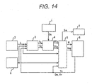
- the embodiment shown in Fig. 14 is to obtain the traveling condition of the preceding vehicle from the control unit installed on the road, and is provided with preceding vehicle information obtaining means 8 in addition to the embodiment of Fig. 1.
- the preceding vehicle information obtaining means 8 can be constructed with communication means 81 and processing means 82 as shown in Fig. 15.
- the communication means 81 receives traveling condition of the preceding vehicle from the control unit on the road using the radio wave or light.
- the processing means 82 outputs the traveling condition of the received preceding vehicle to the intersection arriving time measuring means 3.
- a construction shown in Fig. 16 is considered, for example.
- it is intended to control own vehicle in consideration of the vehicles coming from the opposite direction and foot passengers or the like when the own vehicle turns right or left in the intersection. Therefore, in addition to the construction of the embodiment of Fig. 1, left and right turn control signal generating means 9 is provided.
- the left and right turn control s ignal generating means may also be provided in the embodiment shown in Fig. 14.
- the left and right turn control signal generating means 9 receives state of a turn signal and a route information (go straight, to turn right or to turn left) to the destination generated by the road information obtaining means to generate right or left turn control signal R/L when at least one of the state of the turn signal and the route information indicates right turn or left turn to output to the control content modifying means.
- the control content modifying means 5 modifies the content of cruise control of the own vehicle on the basis of the value of the right or left control signal R/L.
- R/L 1 or 2
- the speed command generate the control mode M to use the speed command Vcop generated by the control content modifying means 5.
- the control mode of the control content modifying means 5 is shown in Fig. 17 corresponding to the right and left turn control signal R/L.
Abstract
Description
- The present invention relates generally to a running control device for a vehicle. More particularly, the invention relates to a cruise control system for an automotive vehicle which can perceive a condition of coming traffic signal installed on a road, on which the own vehicle travels, and appropriately control a speed of the own vehicle and a distance to a preceding vehicle.
- According to advancement of performance of automotive vehicle, it has been more important to provide preventive security by recognizing environmental condition, in which own vehicle travels for detecting a condition where accident tends to occur, to given an alarm to a driver for encouraging taking operation for avoiding danger and preventing accident before occurring by automatically controlling the vehicle in positive manner.
- More particularly, an automatic cruise control systems which measures a distance to a preceding vehicle traveling ahead of own vehicle using a laser radar or a millimeter wave radar for cruising with controlling the distance constant, have been commercialized. While such systems are premised on use on the highway, application of such system for traveling on ordinary roads toward the future.
- Therefore, as prior arts, systems disclosed in Japanese Patent Application Laid-Open No. 3-201100(1991), Japanese Patent Application Laid-Open No. 3-260899(1991)and Japanese Patent Application Laid-Open No. 11-250399(1999). The conventional system disclosed in Japanese Patent Application Laid-Open No. 3-20110 recognizes condition of a traffic signal by image processing to announce a condition of the traffic signal to the driver when the own vehicle reaches a position of a predetermined distance to the traffic signal, and causes deceleration of the vehicle at red light. On the other hand, the conventional system disclosed in Japanese Patent Application Laid-Open No. 3-260899 has means for detecting color information of the traffic signal to stop operation of distance control when a color of the detected traffic signal is a predetermined color.
- On the other hand, the conventional system disclosed in Japanese Patent Application Laid-Open No. 11-250399 receives a distance to an intersection and a condition of the traffic signal from a on-road equipment distanced from the intersection for a predetermined distance, and performs control.
- On the other hand, in the conventional system, a condition of the traffic signal is estimated the condition of the traffic signal when the own vehicle passes through the intersection on the basis of the received distance to the intersection and a speed of the own vehicle and makes judgment whether the own vehicle can stop at the intersection at a predetermined deceleration characteristics. Then, when the own vehicle can stop at the intersection at the predetermined deceleration characteristics but cannot pass through the intersection safely, an alarm is given to the driver. On the other hand, when the own vehicle cannot stop at the intersection at the predetermined deceleration characteristics, an alarm is given to the driver even when the own vehicle can pass the intersection safely.
- However, in the conventional automatic cruise control system, upon traveling on the ordinary road, various drawbacks are encountered. Namely, since the automatic cruising system measures only distance, if the preceding vehicle passes through the intersection at yellow light or red light, the own vehicle can follow the preceding vehicle despite of the fact that the traffic signal is red light.
- On the other hand, since deceleration is taken place only in consideration of the condition of the traffic signal when the own vehicle passes through the intersection, unnecessary deceleration can be caused, and deceleration with taking stoppage of the preceding vehicle into account cannot be performed. Therefore, more delicate vehicle distance control cannot be performed.
- The present invention has been worked out in view of the problems set forth above. Therefore, it is an object of the present invention to provide a cruise control system for an automotive vehicle to control speed of own vehicle estimating conditions not only when the own vehicle passes through the intersection but also when the preceding vehicle passes through the intersection, for permitting travel on the ordinary road with a given distance.
- In order to accomplish the above-mentioned object, a cruise control system for an automotive vehicle, according to one aspect of the present invention, for controlling cruising of own vehicle with maintaining a distance to a preceding vehicle constant, comprises:
- traffic signal characteristics obtaining means for obtaining characteristics of a traffic signal ahead;
- road information obtaining means for obtaining intersection information including a distance to an intersection;
- intersection arrival time calculating means for calculating arrival timing of the own vehicle and the preceding vehicle on the basis of a distance to the intersection, an own vehicle speed and a preceding vehicle traveling condition;
- traffic signal condition estimating means for estimating the condition of the traffic signal on the basis of the traffic signal characteristics and the intersection arriving time; and
- control content modifying means for modifying a content of cruise control of the own vehicle depending upon the estimated traffic signal condition.
-
- On the other hand, in the cruise control system for an automotive vehicle may further comprise right and left turn control signal generating means for generating operation pattern of the own vehicle from a state of turn signal or a route information to a destination generated by the road information obtaining means to input to the control content modifying means.
- The traffic signal characteristics obtaining means may include traffic signal characteristics measuring means for measuring characteristics of the traffic signal and traffic signal characteristics learning means for learning a traffic signal characteristics measured by the traffic signal characteristics measuring means.
- The traffic signal characteristics learning means may learn intersection information from the road information obtaining means with correspondence to the intersection information.
- According to another aspect of the present invention, a cruise control system for an automotive vehicle, for controlling cruising of own vehicle with maintaining a distance to a preceding vehicle constant, comprises:
- traffic signal characteristics obtaining means including image pick-up means having zooming means , image processing means obtaining a traffic signal characteristics by processing an image of the image pick-up means and communication means, for serving as measuring means for obtaining characteristics of a traffic signal ahead;
- road information obtaining means for obtaining intersection information including a distance to an intersection ahead;
- intersection arrival time calculating means for calculating arrival timing of the own vehicle and the preceding vehicle on the basis of a distance to the intersection, an own vehicle speed and a preceding vehicle traveling condition;
- traffic signal condition estimating means for estimating the condition of the traffic signal on the basis of the traffic signal characteristics and the intersection arriving time;
- right and left turn control signal generating means for generating operation pattern of the own vehicle from a state of turn signal or a route information to a destination generated by the road information obtaining means to input to the control content modifying means;
- control content modifying means for modifying a content of cruise control of the own vehicle depending upon the estimated traffic signal condition; and
- alarm means for generating a corresponding alarm beforehand of modifying the content of control.
-
- On the other hand, the cruise control system for the automotive vehicle has communication means for obtaining the traveling condition of the preceding vehicle from outside. On the basis of the traveling condition (distance and relative speed) of the preceding vehicle obtained via the communication means, the intersection arriving time of the preceding vehicle and the signal condition (red, green or yellow) at arrival timing are estimated to perform vehicle control. Here, the traveling condition of the preceding vehicle from the communication means may be the traveling condition of one or more preceding vehicle.
- The present invention will be understood more fully from the detailed description given hereinafter and from the accompanying drawings of the preferred embodiment of the present invention, which, however, should not be taken to be limitative to the invention, but are for explanation and understanding only.
- In the drawings:
- Fig. 1 is a block diagram showing a functional construction of one embodiment of a cruise control system for an automotive vehicle according to the present invention;
- Fig. 2 is an explanatory illustration for the case of obtaining a traffic signal characteristics;
- Fig. 3 is a block diagram showing a construction of road information obtaining means;
- Fig. 4 is an explanatory illustration of a traffic signal condition estimating method;
- Fig. 5 is a block diagram showing a construction of the cruise control system for the automotive vehicle;
- Fig. 6 is a flowchart for discussing a process of target distance setting means and speed command setting means;
- Fig. 7 is a flowchart for discussing a process of vehicle speed control means;
- Fig. 8 is an illustration for discussing a control content modifying method;
- Fig. 9 is an illustration for discussing an example of a speed command Vcop generating method;
- Fig. 10 is an illustration for discussing another example of a speed command Vcop generating method;
- Fig. 11 is a block diagram for discussing a constriction of traffic signal characteristics obtaining means;
- Fig. 12 is a block diagram for discussing a constriction of traffic signal characteristics obtaining means;
- Fig. 13 is a block diagram for discussing another constriction of traffic signal characteristics obtaining means;
- Fig. 14 is a block diagram showing another construction of the cruise control system for the automotive vehicle according to the present invention;
- Fig. 15 is a block diagram showing a construction of preceding vehicle information obtaining means;
- Fig. 16 is a block diagram showing a further construction of the cruise control system for the automotive vehicle according to the present invention; and
- Fig. 17 is an explanatory illustration of a control mode of control content modifying means.
-
- The present invention will be discussed hereinafter in detail in terms of the preferred embodiment of the present invention with reference to the accompanying drawings. In the following description, numerous specific details are set forth in order to provide a thorough understanding of the present invention. It will be obvious, however, to those skilled in the art that the present invention may be practiced without these specific details. In other instance, well-known structure are not shown in detail in order to avoid unnecessary obscurity of the present invention.
- Fig. 1 shows a block diagram of one embodiment of a cruise control system for an automotive vehicle. The shown embodiment of the cruise control system for the automotive vehicle is constructed with traf f ic signal
characteristics obtaining means 1, roadinformation obtaining means 2, intersection arrivingtime calculating means 3, traffic signal condition estimating means 4, controlcontent modifying means 5, cruise control means 6 and alarm means 7, in general. - The traffic signal
characteristics obtaining means 1 is constructed with image pick-up means (101) for picking up an image of a traveling direction of an own vehicle, and image processing means (102, see Fig. 12) for processing the image picked up by the image pick-up means (101), for example. By executing processing procedure which will be discussed later, characteristics Cs of the traffic signal (red light period Tr, green light period Tb, yellow light period Ty and an elapsed time T from beginning of a signal condition cycle to a current time) shown in Fig. 2 is obtained to output to the traffic signal condition predicting means 4. - Here, the characteristics Cs of the traffic signal obtained by traffic signal
characteristics obtaining means 1 is the red light period Tr, the green light period Tb, the yellow light period Ty and the elapsed time T from beginning of the cycle to the current time as taking green, yellow and red light periods as one cycle. The traffic signal characteristics obtaining means can be realized by the image pick-up device, such as a TV camera, and an image processing device, for example, can recognize the traffic signal by processing the image picked up by the image processing device and can measure the green light period, the yellow light period and the read light period with correspondence to the current time. In the alternative, the red light period, the green light period and the yellow light period can be obtained from the traffic signal provided on the road, the control unit or other on-road equipment through communication means. - On the other hand, the road
information obtaining means 2 can be realized by employing a navigation device as means for calculating a distance L to an intersection, to which an own vehicle is approaching, using an own position obtained by GPS or the like and a road map. The roadinformation obtaining means 2 can be constructed with thenavigation device 20 utilizing GPS as shown in Fig. 3 and aGPS antenna 21, for example. Namely, a traveling position of the own vehicle is derived utilizing the GPS to discriminate a road on which the own vehicle is traveling and an intersection, to which the own vehicle is approaching by establishing correspondence between the derived traveling position and the road map stored in thenavigation device 20, to calculate a distance L to the intersection, to which the own vehicle is approaching is calculated from information, such as shape of the road or so forth stored in the road map. Since the discriminated road and the intersection are stored in the road map with assigning unique numbers, the road number and the intersection number can be output together with the discriminated road and the intersection. - When a route calculating function is provided in the navigation device, an optimal route from a starting point to a destination can be calculated, Therefore, on the basis of the route calculated, information to go straight, to turn right or to turn left can also be output.
- The intersection arriving
time calculating means 3 estimates timings to arrive the intersection of the own vehicle and the preceding vehicle, us ing the distance to the intersection, an own vehicle speed and traveling condition of the preceding vehicle (distance and relative speed). Now, assuming that a distance to the intersection output from the roadinformation obtaining means 2 is L, an own vehicle speed output by the cruise control means 6 is V0, the distance to the preceding vehicle is Dm and a relative speed with the preceding vehicle is Vr, a timing Ts and Tp of arrival to the intersection of the own vehicle and the preceding vehicle are estimated by the following equation to output to the traffic signal condition estimating means 4. - On the other hand, traffic signal condition estimating means 4 estimates the signal condition (green light, yellow light or red light) upon arrival to the intersection of the own vehicle and the preceding vehicle on the basis of timing of arrival to the intersection of the own vehicle and the preceding vehicle and the traffic signal characteristics (red light period Tr, green light period Tb, yellow light period Ty and an elapsed time T from beginning of a signal condition cycle to a current time). Then, the traffic
signal condition estimatingmeans 4 estimates conditions STs and STp of the traffic signal upon arrival of the own vehicle and the preceding vehicle as shown in Fig. 4 using the characteristics Cs of the traffic signal output by the traffic signalcharacteristics obtaining means 1 and intersection arriving timing Ts and Tp of the own vehicle and the preceding vehicle output by the intersection arrivingtime calculating means 3. In an example of Fig. 4, there is shown that when the preceding vehicle arrives the intersection, the traffic signal is a red light condition Tr, and when the own vehicle arrives the intersection, the traffic signal is a green light condition Tb. - The control
content modifying means 5 controls traveling of vehicle by making judgment whether a distance control is to be continued or to perform decelerating operation depending upon a deceleration characteristics according to a distance to the intersection and the own vehicle speed depending upon the estimated condition of traffic signal (green light, yellow light or red light) upon arrival to the intersection of the own vehicle and the preceding vehicle. On the other hand, it is also possible to modify the decelerating operation depending upon the signal condition (green light, yellow light or red light) upon arrival to the intersection of the own vehicle and the preceding vehicle. A traveling control mode M and a speed command Vcop are output on the basis of the estimated traffic signal conditions STs and STp output by the traffic signal condition estimating means 4, a distance to the intersection L output by the roadinformation obtaining means 3 and the own vehicle speed V0 output by the cruise control means 6. Furthermore, when a traveling control mode is varied, a control signal Sa for generating an alarm notifying the variation of the traveling control mode to output to the alarm means 7. - The alarm means 7 provides an alarm to the driver by sound, light, vibration or the like before modification of the control content in practice.
- The cruise control means 6 is a control device for driving the own vehicle to travel with maintaining the distance to the preceding vehicle constant, and is constructed as shown in Fig. 5, for example. The cruise control means 6 includes a
radar 605 having a target distance (Dr) setting means 607, a relative speed (Vr) detecting means 602, a distance (Dm) detecting means 604, a speed command (Vcmd) setting means 608, a vehicle speed control means 609, an own vehiclespeed detecting means 610, athrottle actuator 611, atransmission actuator 612 and abrake actuator 613. - As the own vehicle speed detecting means 610 detecting the own vehicle speed Vo, a wheel speed sensor detecting a vehicle speed from a rotation speed of the wheel may be employed, for example. The radar is constructed with a millimeter wave radar for example and has own vehicle speed detecting means and relative speed detecting means 602 for measuring and outputting respective of the distance Dm and the relative speed Vr.
- The target distance setting means 607 sets a target distance Dr on the basis of the own vehicle speed Vo detected by the own vehicle
speed detecting means 610. - In the speed command setting means 608, a speed command Vcmd is set on the basis of the target distance Dr, the measured distance Dm and the measured relative speed Vr.
- The vehicle speed control means 609 derives a throttle valve open degree command, a shift command and a brake command on the basis of the own vehicle speed Vo, the speed command Vcmd, the distance Dm, the relative speed Vr, the control mode M and the speed command Vcop to control the
throttle actuator 611, thetransmission actuator 612 and thebrake actuator 613. - Here, the control
content modifying means 5, the target distance setting means 607, the speed command setting means 608 and the vehicle speed control means 609 may be realized by executing respectively corresponding control programs by a computer, for example. A process corresponding to respective control programs will be discussed hereinafter in detail. - At first, the process to be executed by the target
distance setting portion 607 and the speed command setting means 608 will be discussed with reference to the flowchart of Fig. 6. - At
step 301, the own vehicle speed Vo is taken out from the ownvehicle detecting means 610. Atstep 602, the target distance Dr is set depending upon the own vehicle speed Vo. As these setting method, for example, when the own vehicle speed Vo is lower than 18 km/h, the target distance Dr is set at 10m. When the own vehicle speed Vo is in a range between 18 km/h to 45 km/h, the target distance is increased from 10m in proportion to increasing of the vehicle speed. When the own vehicle speed Vo is 45 km/h, the target distance Dr is set at 25m. Even when the vehicle speed is higher than or equal to 45 km/h, the target distance is increased in proportion to increasing of the own vehicle speed. When the own vehicle speed is 90 km/h, the target speed is set at 75m. As an alternate setting method, a method for deriving the target distance by multiplying the own vehicle speed Vo by a predetermined period (for example, 1 second). - At
step 303, the distance Dm measured by thedistance detecting means 605 is taken out. Furthermore, atstep 304, the measured relative speed Vr is taken out. Atstep 305, the speed command Vcmd is derived from the target distance Dr, the distance Dm, the relative speed Vr and the own vehicle speed Vo by the following equation 1:wherein ki is a coefficient for modifying the target speed depending upon a difference between the target distance Dr and the measured distance Dm when the difference is maintained for a predetermined period, t is the predetermined period, Kp is a coefficient for modifying the target speed depending upon the difference between the target distance Dr and the measured distance Dm, Kd is a coefficient for modifying the target speed depending upon the relative speed. These values are determined by OFF line by simulation, experiments and so forth and are incorporated in a vehicle travel control program as parameters.
- Concerning the process to be executed by the vehicle speed control means 609, discussion will be given with reference to the flowchart in Fig. 7. At
step 401, the control mode M is taken out from the controlcontent modifying means 5. Atstep 402, judgment is made whether the control mode M is designating use of the speed command Vcop generated by the controlcontent modifying means 5. If use of the speed command Vcop is not designated, the process is advanced to step 404, and if use of the speed command Vcop is designated, the process is advanced to step 403. - At
step 403, when the use of the speed command Vcop is designated, the speed command Vcop is taken out from the controlcontent modifying means 5 and set the same as the speed command Vcmd. - At
step 404, a speed control target torque Tcmd is derived by thefollowing equation 2.wherein Kj and Kq are predetermined control constants , in which Kj is a coefficient for modifying a target torque depending upon time integral (distance to move for the predetermined period at a speed of the difference) of the difference between the target speed and the own vehicle speed, and Kq is a coefficient for modifying the target torque depending upon the own vehicle speed.
- At
step 405, the speed control target torque Tcmd is compared with a predetermined target torque threshold value Tth. The target torque threshold value Tth is a threshold value for selecting whether the own vehicle speed Vo is to be controlled mainly using the throttle open degree command or the own vehicle speed Vo is to be controlled mainly using the brake command. When Tcmd ≧ Tth, a process fromstep 406 to step 408 is executed and when Tcmd < Tth, a process fromstep 409 to step 411 is executed. - When Tcmd ≧ Tth, acceleration control mainly using the throttle open degree command and deceleration control mainly using engine braking are performed. At
step 406, the throttle open degree command is set. The throttle open degree command is set from a target engine torque and an engine revolution speed by calculating the target engine torque from a current transmission speed ratio and the speed control target torque Tcmd. This utilizes a relationship between the engine revolution speed, the throttle valve open degree and the engine torque. - Next, at
step 407, a shifting command is set. When the speed command target torque Tcmd requires deceleration by engine braking, the shifting command is set for performing down-shifting. Then, atstep 408, a brake command is set. Here, since it is not required to operate the brake, the brake command is set for releasing the brake. - On the other hand, when Tcmd < Tth, deceleration control is performed mainly using the brake. At
step 409, since deceleration is performed by controlling the brake, the throttle open degree is set to fully close. Atstep 410, a transmission speed ratio of thetransmission actuator 612 is set. Atstep 411, the brake command is set depending upon the speed command target torque Tcmd. Then, on the basis of the throttle open degree command, thethrottle actuator 611 is driven. Thetransmission actuator 612 is driven on the basis of the shift command. Thebrake actuator 613 is driven on the basis of the brake command. Thus, own vehicle speed is controlled. - Next, the process to be executed by the control content modifying means will be discussed with reference to Fig. 8.
- In Fig. 8, (A) shows the condition of the traffic signal upon arrival to the intersection of the own vehicle and the preceding vehicle by ▴ and Δ which can be classified into twelve states depending upon the traffic signal condition of the preceding vehicle, namely (1) to (12). Operation of the control
content modifying means 5 in each state will be discussed hereinafter. - In (A) of Fig. 8, the states (1) to (3) show the condition where no preceding vehicle is present and represents the state where the own vehicle travels at low speed. In this condition, since is only required to consider the condition of the traffic signal when the own vehicle reaches the intersection, the following operation is considered as control mode M of the own vehicle. Hereinafter, the control modes M generated depending upon control states (1) to (12) generated by the control
content modifying means 5 will be shown in (B) of Fig. 8.
State (1): Since the own vehicle enters into the intersection at green light, it is only required to maintain the distance control as is. Accordingly, the control mode commands to use the speed command Vcmd of the speed command setting means 608.
State (2): Since the own vehicle enters into the intersection at yellow light, it is required to stop at the intersection. Accordingly, the control mode M commands to use the speed command Vcop of the controlcontent modifying means 5. As a method for generating the speed command, it is required to set the own vehicle speed zero at the intersection, for example. Therefore, a pattern shown in Fig. 9 using the intersection distance L and the own vehicle speed Vo can be considered.
State (3): Since the own vehicle enters into the intersection at red light, it is required to stop at the intersection. Accordingly, the control mode M commands to use the speed command Vcop of the controlcontent modifying means 5. For the speed command Vcop, the same pattern as the state (2) can be used. - States (4) to (6) show the condition where the preceding vehicle enters into the intersection at green light. In these states, since the similar controls to those at states (1) to (3) are to be performed, the following operations are considered as control modes M of the own vehicle.
State (4): Since the own vehicle enters into the intersection at green light, it is only required to maintain the distance control as is. Accordingly, the control mode commands to use the speed command Vcmd of the speed command setting means 608.
State (5): Since the own vehicle enters into the intersection at yellow light, it is required to stop at the intersection. Accordingly, the control mode M commands to use the speed command Vcop of the controlcontent modifying means 5. As a method for generating the speed command, it is required to set the own vehicle speed zero at the intersection, for example. Therefore, a pattern shown in Fig. 9 using the intersection distance L and the own vehicle speed Vo can be considered.
State (6): Since the own vehicle enters into the intersection at red light, it is required to stop at the intersection. Accordingly, the control mode M commands to use the speed command Vcop of the controlcontent modifying means 5. For the speed command Vcop, the same pattern as the state (5) can be used. - The states (7) to (9) shows the states where the preceding vehicle enters into the intersection at the yellow light. At this condition, it can be considered a case where the preceding vehicle passes through the intersection at the yellow light and a case where the preceding vehicle stops at the yellow light. The control
content modifying means 5 is required to consider the case where the preceding vehicle passes through the intersection, in view point of safety. However, upon generating the speed command Vcop, it may be generated in consideration that the preceding vehicle stops at the intersection. Accordingly, as the control modes M of the own vehicle, the following operations are considered.
State (7): Since the own vehicle enters into the intersection at the yellow light, it is required to stop at the intersection. Accordingly, the control mode M commands to use the speed command Vcop of the controlcontent modifying means 5. As a generation method of the speed command Vcop, similar consideration as the states (5) and (6) is taken, and in consideration that the preceding vehicle stops at the intersection, the own vehicle speed is set to be zero at a point L1 derived by subtracting a value taking the vehicle length of the preceding vehicle into account from the intersection distance L as shown in Fig. 10, for example. As the vehicle length of the preceding vehicle, the vehicle length of a full size vehicle is programmed as default length, or in the alternative, when the traffic signalcharacteristics obtaining means 1 is constructed with the image pick-up device and the image processing device, the number plate of the preceding vehicle is recognized to discriminate the kind of the preceding vehicle to use the vehicle length depending upon the kind of the preceding vehicle.
State (8): Since the own vehicle enters into the red light, it is required to stop at the intersection. Accordingly, the control mode M commands to use the speed command Vcop of the controlcontent modifying means 5. For the speed command Vcop, the same pattern as the state (7) can be used.
State (9): Since the own vehicle enters into the intersection at green light to pass, the distance control can be maintained as is. If the preceding vehicle stops at the yellow signal, the distance control will work. Accordingly, the control mode M command to use the speed command Vcmd of the speed command setting means 608. - States (10) to (12) show the condition where the preceding vehicle enters into the intersection at red light. At this time, it can be considered that the preceding vehicle stops at the intersection, the own vehicle may maintain the distance control. Accordingly, as all of control mode M of states (10) to (12), it is commanded to use the speed command Vcmd of the speed command setting means 608.
- In Fig. 8, as taking that traffic signal conditions of the green light, the yellow light and the read light one cycle, consideration has been given for the case where the traffic signal conditions of the preceding vehicle and the own vehicle falls within one cycle. However, it is possible that the traffic signal conditions of the preceding vehicle and the own vehicle extend over two cycles. It should be noted that, in this case, since it can be considered that a distance to the preceding vehicle is sufficient, it may be possible to perform cruise control or travel control with maintaining distance control until the traffic signal conditions of the preceding vehicle and the own vehicle falls within one cycle as shown in Fig. 8.
- On the other hand, when the control
content modifying means 5 varies the travel control mode M, the control signal Sa (Fig. 1) is generated in order to generate an alarm for notifying this fact to output to the alarm means 7. - The traffic s ignal
characteristics obtaining means 1 shown in Fig. 1 for obtaining the characteristics of the traffic signal (for example, among one cycle of the green light, the yellow light and the red light, red light period Tr, green light period Tb, yellow light period Ty and an elapsed time T from beginning of a signal condition cycle to a current time) is constructed as shown in Fig. 11, for example. The traffic signalcharacteristics obtaining means 1 has a traffic signalcharacteristics measuring means 10 and a learning means 11. In the traffic signalcharacteristics measuring means 10, the characteristics of the traffic signal is measured. On the other hand, in the learning means, the traffic signal characteristics measured by the traffic signalcharacteristics measuring means 10 is stored together with the intersection number or the road number. When the traffic signalcharacteristics measuring means 10 cannot measure the traffic signal characteristics, or measurement is difficult, the stored traffic signal characteristics preliminarily stored is read out by the learning means 11 on the basis of the intersection number or the road number. - The traffic signal
characteristics measuring means 10 is considered to be constructed as shown in Fig. 12. In Fig. 12, there is provided the image pick-up means 101 for picking up image relating to travel of own vehicle and the image processing means 102 for processing the image picked up by the image pick-up means 101. In the construction of Fig. 12, as a method for measuring the traffic signal characteristics, color information of green, yellow and red is detected from the image picked up by the image pick-up means 101 to recognize the traffic signal by making judgment whether the arrangement of green, yellow and red is the same as the traffic signal or not. Then, by performing this process for sequence of images, each period of the green light, the yellow light and the red light are measured. The measured traffic signal characteristics is output to the traffic signal condition estimating means 4, and in conjunction therewith to output to the learning means 11. For example, when the image pick-up means 101 cannot pick up the image of the traffic signal for presence of the large size vehicle in front of the own vehicle, the traffic signal characteristics is read out from the learning means 11 to output the read out information. On the other hand, when a distance to the intersection is long, the image of the traffic signal picked up is small. Therefore, by using a lens having a zooming mechanism, a magnification of the zooming mechanism depending upon the distance to the lens is derived to generate a zoom control signal Zm to control the zoom lens. - Another construction of the traffic signal
characteristics measuring means 10 is shown in Fig. 13. The construction of Fig. 13 is to obtain the characteristics of the traffic signal from the traffic signal installed on the road or the control unit thereof through the communication means. The traffic signalcharacteristics measuring means 10 can be realized by the communication means 103 using radio wave or light. In the communication means, the measured traffic signal characteristics Cs is output to the traffic signal condition estimating means 4 and also to the learning means 11. - The learning means 11 can be realized using a memory, for example.
- In the embodiment of the present invention shown in Fig. 1, a traveling condition (distance and relative speed) of the preceding vehicle is obtained from the cruise control means 6. However, it is also possible to have a construction shown in Fig, 14 as a further embodiment of the present invention. The embodiment shown in Fig. 14 is to obtain the traveling condition of the preceding vehicle from the control unit installed on the road, and is provided with preceding vehicle
information obtaining means 8 in addition to the embodiment of Fig. 1. The preceding vehicleinformation obtaining means 8 can be constructed with communication means 81 and processing means 82 as shown in Fig. 15. The communication means 81 receives traveling condition of the preceding vehicle from the control unit on the road using the radio wave or light. The processing means 82 outputs the traveling condition of the received preceding vehicle to the intersection arrivingtime measuring means 3. - When the embodiment shown in Fig. 14 is used, it becomes possible to obtain traveling condition of a plurality of preceding vehicles traveling around the own vehicle from the control unit on the road. In this case, since the intersection arriving time and the traffic signal condition can be estimated for the vehicle traveling ahead of the preceding vehicle which the own vehicle follows. Therefore, further precise control can be realized to contribute for improvement of riding comfort.
- Furthermore, as the embodiment for realizing the present invention, a construction shown in Fig. 16 is considered, for example. In the embodiment shown in Fig. 16, it is intended to control own vehicle in consideration of the vehicles coming from the opposite direction and foot passengers or the like when the own vehicle turns right or left in the intersection. Therefore, in addition to the construction of the embodiment of Fig. 1, left and right turn control signal generating means 9 is provided. The left and right turn control s ignal generating means may also be provided in the embodiment shown in Fig. 14.
- The left and right turn control signal generating means 9 receives state of a turn signal and a route information (go straight, to turn right or to turn left) to the destination generated by the road information obtaining means to generate right or left turn control signal R/L when at least one of the state of the turn signal and the route information indicates right turn or left turn to output to the control content modifying means. The right or left turn control signal R/L has a pattern that R/L = 0 when own vehicle has to go straight through the intersection, R/L = 1 when the own vehicle has to turn right in the intersection and R/L = 2 when the own vehicle has to turn left in the intersection. The control
content modifying means 5 modifies the content of cruise control of the own vehicle on the basis of the value of the right or left control signal R/L. For example, the operating conditions (1) to (12) of the controlcontent modifying means 5 depending upon signal condition of the own vehicle and the preceding vehicle is only for the case of R/L = 0 (straight). When R/L = 1 or 2, an alarm for announcing necessity of checking the vehicles coming from theopposite direction and foot passengers for the driver. Also, the speed command generate the control mode M to use the speed command Vcop generated by the controlcontent modifying means 5. The control mode of the controlcontent modifying means 5 is shown in Fig. 17 corresponding to the right and left turn control signal R/L. - With the present invention, upon traveling on the ordinary road following the preceding vehicle, entering into the intersection at the yellow light following the preceding vehicle can be avoided to permit traveling of the driver without causing fear of insecurity.
- Although the present invention has been illustrated and described with respect to exemplary embodiment thereof, it should be understood by those skilled in the art that the foregoing and various other changes, omission and additions may be made therein and thereto, without departing from the spirit and scope of the present invention. Therefore, the present invention should not be understood as limited to the specific embodiment set out above but to include all possible embodiments which can be embodied within a scope encompassed and equivalent thereof with respect to the feature set out in the appended claims.
Claims (10)
- An image processing apparatus, comprising:wherein the traffic signal characteristics measuring means (10) is mountable on a vehicle and measures characteristics of the traffic signal including at least one of: a red light period, a green light period, a yellow light period, and an elapsed time T from a beginning of a signal condition cycle to a current time.traffic signal characteristics obtaining means (1) for obtaining traffic signal characteristics, said traffic signal characteristics obtaining means (1) including traffic signal characteristics measuring means (10); and
- The apparatus according to claim 1, wherein the traffic signal characteristics measuring means (10) comprises:an image pick-up device (101) supplying an image of a traffic signal; andan image processor (102) for processing the supplied image to recognize the traffic signal and measure the characteristics thereof.
- The apparatus according to claim 2, wherein the image pick-up device (101) includes a zoom device, and further wherein the image processor (102) provides a zoom control signal to the zoom device.
- The apparatus according to at least one of claims 1 to 3, wherein the traffic signal measuring means (10) includes a communication device (103) which receives the characteristics of the traffic signal from the traffic signal installed on a road or a control unit of the traffic signal.
- The apparatus according to at least one of claims 1 to 4, wherein the traffic signal characteristics obtaining means (1) further includes a learning device (11), said learning device (11) storing the traffic signal characteristics from the traffic signal characteristics measuring means (10).
- A cruise control system for a vehicle, comprising:wherein the traffic signal characteristics measuring means (10) is mountable on a vehicle and measures characteristics of the traffic signal including at least one of: a red light period, a green light period, a yellow light period, and an elapsed time T from a beginning of a signal condition cycle to a current time; andan image processing apparatus including traffic signal characteristics obtaining means (1) for obtaining traffic signal characteristics, said traffic signal characteristics obtaining means (1) including traffic signal characteristics measuring means (10);
an adaptive cruise controller receiving the traffic signal characteristics, the cruise controller operating to control cruising of the vehicle in accordance with the traffic signal characteristics. - The system according to claim 6, wherein the traffic signal characteristics measuring means (10) comprises:an image pick-up device (101) supplying an image of a traffic signal; andan image processor (102) for processing the supplied image to recognize the traffic signal and measure the characteristics thereof.
- The system according to claim 7, wherein the image pick-up device (101) includes a zoom device, and further wherein the image processor (102) provides a zoom control signal to the zoom device.
- The system according to at least one of claims 6 to 8, wherein the traffic signal measuring means (10) includes a communication device (103) which receives the characteristics of the traffic signal from the traffic signal installed on a road or a control unit of the traffic signal.
- The system according to at least one of claims 6 to 9, wherein the traffic signal characteristics obtaining means (1) further includes a learning device (11), said learning device (11) storing the traffic signal characteristics from the traffic signal characteristics measuring means (10).
Applications Claiming Priority (3)
| Application Number | Priority Date | Filing Date | Title |
|---|---|---|---|
| JP2000052179 | 2000-02-23 | ||
| JP2000052179A JP3646605B2 (en) | 2000-02-23 | 2000-02-23 | Vehicle travel control device |
| EP01103665A EP1127727B1 (en) | 2000-02-23 | 2001-02-23 | Cruise control device for a vehicle |
Related Parent Applications (1)
| Application Number | Title | Priority Date | Filing Date |
|---|---|---|---|
| EP01103665A Division EP1127727B1 (en) | 2000-02-23 | 2001-02-23 | Cruise control device for a vehicle |
Publications (4)
| Publication Number | Publication Date |
|---|---|
| EP1481837A2 true EP1481837A2 (en) | 2004-12-01 |
| EP1481837A3 EP1481837A3 (en) | 2006-06-14 |
| EP1481837A9 EP1481837A9 (en) | 2006-08-16 |
| EP1481837B1 EP1481837B1 (en) | 2008-08-27 |
Family
ID=18573737
Family Applications (2)
| Application Number | Title | Priority Date | Filing Date |
|---|---|---|---|
| EP01103665A Expired - Lifetime EP1127727B1 (en) | 2000-02-23 | 2001-02-23 | Cruise control device for a vehicle |
| EP04020858A Expired - Lifetime EP1481837B1 (en) | 2000-02-23 | 2001-02-23 | Image processing system for cruise control system |
Family Applications Before (1)
| Application Number | Title | Priority Date | Filing Date |
|---|---|---|---|
| EP01103665A Expired - Lifetime EP1127727B1 (en) | 2000-02-23 | 2001-02-23 | Cruise control device for a vehicle |
Country Status (4)
| Country | Link |
|---|---|
| US (2) | US6516262B2 (en) |
| EP (2) | EP1127727B1 (en) |
| JP (1) | JP3646605B2 (en) |
| DE (2) | DE60106794T2 (en) |
Cited By (4)
| Publication number | Priority date | Publication date | Assignee | Title |
|---|---|---|---|---|
| CN105006166A (en) * | 2015-08-14 | 2015-10-28 | 太仓苏易信息科技有限公司 | Intelligent road condition broadcasting system |
| CN106157668A (en) * | 2016-08-29 | 2016-11-23 | 天津思博科科技发展有限公司 | Highway cruise information sharing device |
| JP2017207880A (en) * | 2016-05-18 | 2017-11-24 | トヨタ自動車株式会社 | Support device |
| CN111862635A (en) * | 2020-02-28 | 2020-10-30 | 重庆长安汽车股份有限公司 | Traffic signal lamp-based vehicle speed control method and device and automobile |
Families Citing this family (137)
| Publication number | Priority date | Publication date | Assignee | Title |
|---|---|---|---|---|
| US6822563B2 (en) | 1997-09-22 | 2004-11-23 | Donnelly Corporation | Vehicle imaging system with accessory control |
| US5877897A (en) | 1993-02-26 | 1999-03-02 | Donnelly Corporation | Automatic rearview mirror, vehicle lighting control and vehicle interior monitoring system using a photosensor array |
| US6891563B2 (en) | 1996-05-22 | 2005-05-10 | Donnelly Corporation | Vehicular vision system |
| US7655894B2 (en) | 1996-03-25 | 2010-02-02 | Donnelly Corporation | Vehicular image sensing system |
| US6882287B2 (en) | 2001-07-31 | 2005-04-19 | Donnelly Corporation | Automotive lane change aid |
| US6609057B2 (en) * | 2002-01-23 | 2003-08-19 | Ford Global Technologies, Llc | Method and apparatus for activating a crash countermeasure using a transponder having various modes of operation |
| DE10210547A1 (en) * | 2002-03-09 | 2003-09-18 | Bosch Gmbh Robert | Speed controller with stop & go function |
| US7038577B2 (en) | 2002-05-03 | 2006-05-02 | Donnelly Corporation | Object detection system for vehicle |
| JP3918686B2 (en) * | 2002-08-30 | 2007-05-23 | 株式会社日立製作所 | Driving control apparatus and control method for automobile |
| US6882923B2 (en) * | 2002-10-17 | 2005-04-19 | Ford Global Technologies, Llc | Adaptive cruise control system using shared vehicle network data |
| DE10254582A1 (en) * | 2002-11-22 | 2004-06-03 | Robert Bosch Gmbh | Speed controller with multiple operating modes |
| JP3928571B2 (en) | 2003-03-14 | 2007-06-13 | トヨタ自動車株式会社 | Vehicle driving assistance device |
| KR20040091788A (en) * | 2003-04-22 | 2004-11-02 | 현대자동차주식회사 | Self-control Traveling System For Expressway and Control Method Thereof |
| US10964209B2 (en) | 2003-12-24 | 2021-03-30 | Mark W. Publicover | Method and system for traffic and parking management |
| US7663505B2 (en) * | 2003-12-24 | 2010-02-16 | Publicover Mark W | Traffic management device and system |
| JP4681541B2 (en) * | 2004-03-29 | 2011-05-11 | パイオニア株式会社 | MAP INFORMATION DISPLAY CONTROL DEVICE, ITS SYSTEM, ITS METHOD, ITS PROGRAM, AND RECORDING MEDIUM CONTAINING THE PROGRAM |
| US7526103B2 (en) | 2004-04-15 | 2009-04-28 | Donnelly Corporation | Imaging system for vehicle |
| GB2414588A (en) * | 2004-05-26 | 2005-11-30 | Charles Alasdair Fairbairn | Device for warning following traffic of a vehicle ahead. |
| JP4622330B2 (en) * | 2004-06-18 | 2011-02-02 | トヨタ自動車株式会社 | Vehicle travel control device |
| JP4507815B2 (en) | 2004-07-09 | 2010-07-21 | アイシン・エィ・ダブリュ株式会社 | Signal information creating method, signal guide information providing method, and navigation apparatus |
| US7881496B2 (en) | 2004-09-30 | 2011-02-01 | Donnelly Corporation | Vision system for vehicle |
| JP2006131055A (en) * | 2004-11-04 | 2006-05-25 | Denso Corp | Vehicle traveling controlling device |
| JP2006293553A (en) * | 2005-04-07 | 2006-10-26 | Aisin Aw Co Ltd | Rotation processor for font data and map display system |
| JP4548279B2 (en) * | 2005-08-30 | 2010-09-22 | マツダ株式会社 | Follow-up device for automobile |
| JP4425229B2 (en) * | 2006-03-03 | 2010-03-03 | 雅弘 渡邉 | Vehicle travel control method |
| JP4882499B2 (en) * | 2006-05-10 | 2012-02-22 | 株式会社デンソー | Speed information providing apparatus and program |
| WO2007142326A1 (en) | 2006-06-09 | 2007-12-13 | Aisin Aw Co., Ltd. | Data update system, terminal device, server device, and data update method |
| WO2008024639A2 (en) | 2006-08-11 | 2008-02-28 | Donnelly Corporation | Automatic headlamp control system |
| US20080088479A1 (en) * | 2006-10-13 | 2008-04-17 | Toyota Engineering & Manufacturing North America, Inc. | Traffic light warning method and system |
| US8755991B2 (en) | 2007-01-24 | 2014-06-17 | Tomtom Global Assets B.V. | Method and structure for vehicular traffic prediction with link interactions and missing real-time data |
| US20080183344A1 (en) * | 2007-01-30 | 2008-07-31 | Arinc Inc. | Systems and methods for communicating restricted area alerts |
| CN101542552B (en) * | 2007-02-02 | 2011-05-18 | 丰田自动车株式会社 | Vehicle-mounted receiver apparatus |
| US8155826B2 (en) * | 2007-03-30 | 2012-04-10 | Aisin Aw Co., Ltd. | Vehicle behavior learning apparatuses, methods, and programs |
| JP4446201B2 (en) | 2007-03-30 | 2010-04-07 | アイシン・エィ・ダブリュ株式会社 | Image recognition apparatus and image recognition method |
| JP2008265503A (en) * | 2007-04-19 | 2008-11-06 | Mazda Motor Corp | Travel controller for vehicle |
| DE102007025502A1 (en) * | 2007-06-01 | 2008-12-04 | Zf Friedrichshafen Ag | Operating and driving control device for a motor vehicle and method thereto |
| WO2009030532A1 (en) * | 2007-08-29 | 2009-03-12 | Continental Teves Ag & Co. Ohg | Speed control for a motor vehicle |
| DE102007043602A1 (en) * | 2007-09-13 | 2009-03-19 | Robert Bosch Gmbh | Method for adjusting the speed of a vehicle in front of a signal system and vehicle system |
| JP4501983B2 (en) | 2007-09-28 | 2010-07-14 | アイシン・エィ・ダブリュ株式会社 | Parking support system, parking support method, parking support program |
| JP4793452B2 (en) * | 2007-10-11 | 2011-10-12 | トヨタ自動車株式会社 | Driving assistance device |
| JP4375488B2 (en) * | 2007-10-11 | 2009-12-02 | トヨタ自動車株式会社 | Driving assistance device |
| EP2232458B1 (en) | 2007-12-13 | 2018-06-27 | Continental Teves AG & Co. oHG | Method and device for assisting a vehicle operator |
| JP4483958B2 (en) * | 2008-03-12 | 2010-06-16 | トヨタ自動車株式会社 | Driving support device |
| JP4930446B2 (en) * | 2008-04-14 | 2012-05-16 | トヨタ自動車株式会社 | Vehicle travel control device |
| US8344906B2 (en) | 2008-09-08 | 2013-01-01 | International Business Machines Corporation | Automated traffic synchronization |
| US20100088002A1 (en) * | 2008-10-07 | 2010-04-08 | Welte Gregory A | System for increasing fuel economy in vehicles |
| JP5025617B2 (en) * | 2008-10-24 | 2012-09-12 | 三菱電機株式会社 | Information providing apparatus and information providing method |
| US20100145587A1 (en) * | 2008-11-07 | 2010-06-10 | Myunghee Son | Method and apparatus for managing traffic information using light communication |
| EP2381431B1 (en) * | 2008-12-25 | 2013-07-03 | Toyota Jidosha Kabushiki Kaisha | Drive assistance apparatus |
| EP2407951B1 (en) * | 2009-03-11 | 2017-12-27 | Toyota Jidosha Kabushiki Kaisha | Driving supporting device |
| US8033349B2 (en) * | 2009-03-12 | 2011-10-11 | Ford Global Technologies, Inc. | Auto-seek electrical connection for a plug-in hybrid electric vehicle |
| JP5375301B2 (en) * | 2009-04-16 | 2013-12-25 | トヨタ自動車株式会社 | Vehicle speed control device |
| JP4957747B2 (en) * | 2009-05-18 | 2012-06-20 | トヨタ自動車株式会社 | Vehicle environment estimation device |
| JP5088349B2 (en) * | 2009-06-01 | 2012-12-05 | トヨタ自動車株式会社 | Vehicle travel control device |
| JP5332993B2 (en) * | 2009-07-15 | 2013-11-06 | トヨタ自動車株式会社 | Travel plan generator |
| US8478500B1 (en) * | 2009-09-01 | 2013-07-02 | Clemson University | System and method for utilizing traffic signal information for improving fuel economy and reducing trip time |
| KR101203714B1 (en) * | 2009-10-07 | 2012-11-21 | 한국전자통신연구원 | System and Method for Providing Driving Safety |
| JPWO2011125185A1 (en) * | 2010-04-07 | 2013-07-08 | トヨタ自動車株式会社 | Vehicle travel support device |
| US8260482B1 (en) | 2010-04-28 | 2012-09-04 | Google Inc. | User interface for displaying internal state of autonomous driving system |
| US8346426B1 (en) | 2010-04-28 | 2013-01-01 | Google Inc. | User interface for displaying internal state of autonomous driving system |
| FR2960651B1 (en) * | 2010-05-28 | 2013-08-23 | Thales Sa | METHOD FOR CORRECTING REFLECTIVITY MEASUREMENTS AND RADAR USING THE SAME |
| US8509982B2 (en) | 2010-10-05 | 2013-08-13 | Google Inc. | Zone driving |
| JP5640705B2 (en) * | 2010-12-07 | 2014-12-17 | トヨタ自動車株式会社 | Vehicle control device |
| JP5316531B2 (en) * | 2010-12-28 | 2013-10-16 | 株式会社デンソー | Driving assistance device |
| US8738289B2 (en) | 2011-01-04 | 2014-05-27 | International Business Machines Corporation | Advanced routing of vehicle fleets |
| DE102011009106A1 (en) | 2011-01-21 | 2012-07-26 | Audi Ag | Method for operating a driver assistance system of a motor vehicle and motor vehicle issuing a recommendation relating to a passing process |
| US8504270B2 (en) * | 2011-02-16 | 2013-08-06 | Bayerische Motoren Werke Aktiengesellschaft | Traffic broadcast system |
| JP5427203B2 (en) * | 2011-03-30 | 2014-02-26 | 富士重工業株式会社 | Vehicle driving support device |
| DE102011007132A1 (en) * | 2011-04-11 | 2012-10-11 | Robert Bosch Gmbh | Method for energy-saving operation control of motor car, involves outputting signal for adaption of travel course in particular velocity of car such that threshold value of spacing is not exceeded |
| WO2012144255A1 (en) | 2011-04-21 | 2012-10-26 | 三菱電機株式会社 | Drive assistance device |
| US8620032B2 (en) * | 2011-05-10 | 2013-12-31 | GM Global Technology Operations LLC | System and method for traffic signal detection |
| DE102011106320A1 (en) * | 2011-07-01 | 2013-01-03 | Continental Teves Ag & Co. Ohg | Method for preventing collision of force-driving train, involves detecting risk of collision when speed of preceding vehicle is decreased and speed of ego-vehicle is increased, and introducing measure for collision prevention |
| JP2013097621A (en) * | 2011-11-01 | 2013-05-20 | Toyota Motor Corp | Drive support device |
| JP2013097620A (en) * | 2011-11-01 | 2013-05-20 | Toyota Motor Corp | Driving support device |
| JP5397452B2 (en) * | 2011-11-01 | 2014-01-22 | トヨタ自動車株式会社 | Driving assistance device |
| EP2794331A4 (en) * | 2011-12-22 | 2016-07-13 | Scania Cv Ab | Module and method pertaining to mode choice when determining reference values |
| US10457209B2 (en) | 2012-02-22 | 2019-10-29 | Magna Electronics Inc. | Vehicle vision system with multi-paned view |
| US9145140B2 (en) | 2012-03-26 | 2015-09-29 | Google Inc. | Robust method for detecting traffic signals and their associated states |
| US9319637B2 (en) | 2012-03-27 | 2016-04-19 | Magna Electronics Inc. | Vehicle vision system with lens pollution detection |
| JP2013215067A (en) * | 2012-04-04 | 2013-10-17 | Honda Motor Co Ltd | Electric vehicle driving support system |
| US8761991B1 (en) * | 2012-04-09 | 2014-06-24 | Google Inc. | Use of uncertainty regarding observations of traffic intersections to modify behavior of a vehicle |
| US8718861B1 (en) | 2012-04-11 | 2014-05-06 | Google Inc. | Determining when to drive autonomously |
| US8793046B2 (en) | 2012-06-01 | 2014-07-29 | Google Inc. | Inferring state of traffic signal and other aspects of a vehicle's environment based on surrogate data |
| US9158980B1 (en) | 2012-09-19 | 2015-10-13 | Google Inc. | Use of relationship between activities of different traffic signals in a network to improve traffic signal state estimation |
| DE102012108863A1 (en) * | 2012-09-20 | 2014-05-28 | Continental Teves Ag & Co. Ohg | Method for recognizing state of traffic light using camera, involves recording sequence of images of vehicle surrounding by camera, recognizing probable presence of traffic light from image data, and classifying current traffic state |
| US8831813B1 (en) | 2012-09-24 | 2014-09-09 | Google Inc. | Modifying speed of an autonomous vehicle based on traffic conditions |
| US9633564B2 (en) | 2012-09-27 | 2017-04-25 | Google Inc. | Determining changes in a driving environment based on vehicle behavior |
| US8949016B1 (en) | 2012-09-28 | 2015-02-03 | Google Inc. | Systems and methods for determining whether a driving environment has changed |
| US9665101B1 (en) | 2012-09-28 | 2017-05-30 | Waymo Llc | Methods and systems for transportation to destinations by a self-driving vehicle |
| US9707896B2 (en) | 2012-10-15 | 2017-07-18 | Magna Electronics Inc. | Vehicle camera lens dirt protection via air flow |
| US9208684B2 (en) * | 2012-11-01 | 2015-12-08 | Verizon Patent And Licensing Inc. | Travel optimization system |
| KR101997430B1 (en) * | 2012-11-08 | 2019-10-01 | 현대모비스 주식회사 | SCC system for car and method of control the same |
| USD735214S1 (en) | 2012-11-30 | 2015-07-28 | Google Inc. | Display screen or portion thereof with graphical user interface |
| US8825258B2 (en) | 2012-11-30 | 2014-09-02 | Google Inc. | Engaging and disengaging for autonomous driving |
| DE102013001017A1 (en) * | 2013-01-22 | 2014-07-24 | GM Global Technology Operations LLC (n. d. Gesetzen des Staates Delaware) | Method for operating motor vehicle e.g. passenger car, involves determining whether vehicle adjusts light signal system during transition phase based on determined distance of vehicle to light signal system and determined speed of vehicle |
| WO2014115309A1 (en) | 2013-01-25 | 2014-07-31 | 三菱電機株式会社 | Movement assistance device and move ment assistance method |
| US9092986B2 (en) * | 2013-02-04 | 2015-07-28 | Magna Electronics Inc. | Vehicular vision system |
| US9445057B2 (en) | 2013-02-20 | 2016-09-13 | Magna Electronics Inc. | Vehicle vision system with dirt detection |
| USD750663S1 (en) | 2013-03-12 | 2016-03-01 | Google Inc. | Display screen or a portion thereof with graphical user interface |
| US8676431B1 (en) | 2013-03-12 | 2014-03-18 | Google Inc. | User interface for displaying object-based indications in an autonomous driving system |
| USD754189S1 (en) | 2013-03-13 | 2016-04-19 | Google Inc. | Display screen or portion thereof with graphical user interface |
| USD754190S1 (en) | 2013-03-13 | 2016-04-19 | Google Inc. | Display screen or portion thereof with graphical user interface |
| FR3006088B1 (en) * | 2013-05-27 | 2015-11-27 | Renault Sas | DEVICE FOR ESTIMATING THE PERMANENT MODE OF OPERATION OF A MOTOR VEHICLE AND ASSOCIATED METHOD |
| CN103337186B (en) * | 2013-06-08 | 2015-08-26 | 华中科技大学 | A kind of crossing driving assist system for motor vehicle |
| DE102013223022A1 (en) * | 2013-11-12 | 2015-05-13 | Bayerische Motoren Werke Aktiengesellschaft | Prediction of the signals of a traffic light |
| JP2015123831A (en) * | 2013-12-26 | 2015-07-06 | 富士重工業株式会社 | Control device and control method of vehicle |
| CN111199218A (en) | 2014-01-30 | 2020-05-26 | 移动眼视力科技有限公司 | Control system for vehicle, and image analysis system |
| US9465388B1 (en) | 2014-03-03 | 2016-10-11 | Google Inc. | Remote assistance for an autonomous vehicle in low confidence situations |
| US9720410B2 (en) | 2014-03-03 | 2017-08-01 | Waymo Llc | Remote assistance for autonomous vehicles in predetermined situations |
| DE102014204059A1 (en) * | 2014-03-05 | 2015-09-10 | Conti Temic Microelectronic Gmbh | Driver assistance system for calculating a future traffic light phase |
| CN103886768B (en) * | 2014-04-11 | 2016-03-30 | 黑龙江大学 | Be arranged on the transmitting of digitizing traffic signals, receiving system in motor vehicle |
| EP2945140A1 (en) * | 2014-05-12 | 2015-11-18 | AVL List GmbH | System and method for operating a vehicle taking into account information on traffic lights and surrounding vehicles |
| US9550498B2 (en) | 2014-05-13 | 2017-01-24 | Ford Global Technologies, Llc | Traffic light anticipation |
| US9321461B1 (en) | 2014-08-29 | 2016-04-26 | Google Inc. | Change detection using curve alignment |
| US9248834B1 (en) | 2014-10-02 | 2016-02-02 | Google Inc. | Predicting trajectories of objects based on contextual information |
| FR3027109B1 (en) * | 2014-10-08 | 2019-05-31 | Valeo Schalter Und Sensoren Gmbh | DETERMINING AN OPTIMUM SPEED FOR A MOTOR VEHICLE APPROACHING A TRICOLOR FIRE |
| CN104464333B (en) * | 2014-12-02 | 2017-11-14 | 曹永飞 | A kind of traffic signal information method for pushing applied to bus or train route coordination technique |
| US10495469B2 (en) * | 2015-06-23 | 2019-12-03 | Ford Global Technologies, Llc | Rapid traffic parameter estimation |
| DE102015224112A1 (en) * | 2015-12-02 | 2017-06-08 | Bayerische Motoren Werke Aktiengesellschaft | System for influencing vehicle systems by considering relevant signal transmitters |
| WO2017161498A1 (en) | 2016-03-22 | 2017-09-28 | 华为技术有限公司 | Vehicle control method, apparatus and system |
| US10297151B2 (en) * | 2016-05-16 | 2019-05-21 | Ford Global Technologies, Llc | Traffic lights control for fuel efficiency |
| US10190560B2 (en) | 2016-06-03 | 2019-01-29 | Magna Electronics Inc. | Camera based vehicle start-stop feature |
| DE102016007035B4 (en) * | 2016-06-08 | 2021-12-23 | Audi Ag | Method for operating a device of a motor vehicle and associated motor vehicle |
| CN106408975B (en) * | 2016-06-17 | 2018-10-19 | 京东方科技集团股份有限公司 | Vehicle travels prediction technique, device and vehicle intelligent system |
| EP3333827A1 (en) * | 2016-12-12 | 2018-06-13 | Hitachi, Ltd. | Driving assistance apparatus with human machine interface system |
| US10493988B2 (en) * | 2017-07-01 | 2019-12-03 | TuSimple | System and method for adaptive cruise control for defensive driving |
| CN108091155B (en) | 2017-11-13 | 2020-04-28 | 华为技术有限公司 | Traffic flow control method and device in Internet of vehicles |
| KR20200050155A (en) * | 2018-11-01 | 2020-05-11 | 현대자동차주식회사 | Method of driving control using traffic light information and vehicle for carrying out the same |
| JP2020076448A (en) * | 2018-11-07 | 2020-05-21 | ジヤトコ株式会社 | Vehicle controller |
| KR102645062B1 (en) * | 2019-06-27 | 2024-03-11 | 현대자동차주식회사 | Apparatus and method for controlling transmission of vehicle |
| CN110588649B (en) * | 2019-09-27 | 2020-12-25 | 北京邮电大学 | Vehicle speed control method, device and equipment based on traffic system and storage medium |
| DE102020126679A1 (en) | 2020-10-12 | 2022-04-14 | Bayerische Motoren Werke Aktiengesellschaft | Vehicle guidance system and method for operating a driving function depending on a vehicle in front |
| CN112699754B (en) * | 2020-12-23 | 2023-07-18 | 北京百度网讯科技有限公司 | Signal lamp identification method, device, equipment and storage medium |
| CN114694396A (en) * | 2020-12-29 | 2022-07-01 | 奥迪股份公司 | Method, apparatus, electronic device, vehicle, and medium for controlling vehicle |
| US20220281451A1 (en) * | 2021-03-04 | 2022-09-08 | GM Global Technology Operations LLC | Target vehicle state identification for automated driving adaptation in vehicles control |
| US11661088B2 (en) * | 2021-03-05 | 2023-05-30 | Toyota Motor Engineering & Manufacturing North America, Inc. | System and method for scheduling connected vehicles to cross non-signalized intersections |
| CN113299029B (en) * | 2021-05-14 | 2022-11-15 | 大旗时代(天津)科技有限公司 | Wisdom fire control remote monitering system |
Citations (2)
| Publication number | Priority date | Publication date | Assignee | Title |
|---|---|---|---|---|
| JPH03260899A (en) * | 1990-03-12 | 1991-11-20 | Mazda Motor Corp | Controller for distance between cars |
| US5940010A (en) * | 1997-07-31 | 1999-08-17 | Toyota Jidosha Kabushiki Kaisha | Intersection warning system |
Family Cites Families (15)
| Publication number | Priority date | Publication date | Assignee | Title |
|---|---|---|---|---|
| JPH035866A (en) | 1989-06-01 | 1991-01-11 | Nec Software Kansai Ltd | On-line program control system |
| JPH03201100A (en) | 1989-12-28 | 1991-09-02 | Matsushita Electric Ind Co Ltd | Traffic signal recognition device |
| JP3005866B2 (en) | 1990-03-22 | 2000-02-07 | 光洋精工株式会社 | Car safe driving system |
| US6498620B2 (en) * | 1993-02-26 | 2002-12-24 | Donnelly Corporation | Vision system for a vehicle including an image capture device and a display system having a long focal length |
| JP3260899B2 (en) | 1993-03-31 | 2002-02-25 | 芝浦メカトロニクス株式会社 | Wire bonding equipment |
| JP3201100B2 (en) | 1993-10-25 | 2001-08-20 | 松下電器産業株式会社 | Magneto-optical disk spindle motor |
| JPH08285942A (en) | 1995-04-11 | 1996-11-01 | Yazaki Corp | Laser radar for vehicle |
| DE69736216T2 (en) * | 1996-04-12 | 2007-05-16 | Equos Research Co. Ltd. | VEHICLE CONTROL |
| JP3945596B2 (en) | 1997-06-18 | 2007-07-18 | ステラケミファ株式会社 | How to recover polyester |
| JPH11175897A (en) | 1997-12-16 | 1999-07-02 | Hitachi Ltd | Cruise control device |
| US6546119B2 (en) * | 1998-02-24 | 2003-04-08 | Redflex Traffic Systems | Automated traffic violation monitoring and reporting system |
| JP3724177B2 (en) | 1998-02-26 | 2005-12-07 | トヨタ自動車株式会社 | In-vehicle intersection warning device |
| JP3548684B2 (en) | 1998-05-07 | 2004-07-28 | 株式会社日立製作所 | Environment recognition vehicle control device |
| JPH11328598A (en) * | 1998-05-18 | 1999-11-30 | Toyota Motor Corp | Intersection alarm system |
| DE10028130C2 (en) * | 2000-06-07 | 2003-08-21 | Daimler Chrysler Ag | System for vehicle guidance in front of traffic-controlled intersections |
-
2000
- 2000-02-23 JP JP2000052179A patent/JP3646605B2/en not_active Expired - Lifetime
-
2001
- 2001-02-23 US US09/790,555 patent/US6516262B2/en not_active Expired - Lifetime
- 2001-02-23 DE DE60106794T patent/DE60106794T2/en not_active Expired - Lifetime
- 2001-02-23 DE DE60135585T patent/DE60135585D1/en not_active Expired - Lifetime
- 2001-02-23 EP EP01103665A patent/EP1127727B1/en not_active Expired - Lifetime
- 2001-02-23 EP EP04020858A patent/EP1481837B1/en not_active Expired - Lifetime
-
2002
- 2002-11-05 US US10/287,550 patent/US6728623B2/en not_active Expired - Fee Related
Patent Citations (2)
| Publication number | Priority date | Publication date | Assignee | Title |
|---|---|---|---|---|
| JPH03260899A (en) * | 1990-03-12 | 1991-11-20 | Mazda Motor Corp | Controller for distance between cars |
| US5940010A (en) * | 1997-07-31 | 1999-08-17 | Toyota Jidosha Kabushiki Kaisha | Intersection warning system |
Non-Patent Citations (2)
| Title |
|---|
| FRANKE U ET AL: "Autonomous driving goes downtown" IEEE INTELLIGENT SYSTEMS, NOV.-DEC. 1998, IEEE, USA, vol. 13, no. 6, 1998, pages 40-48, XP002201164 ISSN: 1094-7167 * |
| PATENT ABSTRACTS OF JAPAN vol. 016, no. 068 (P-1314), 19 February 1992 (1992-02-19) -& JP 03 260899 A (MAZDA MOTOR CORP), 20 November 1991 (1991-11-20) * |
Cited By (4)
| Publication number | Priority date | Publication date | Assignee | Title |
|---|---|---|---|---|
| CN105006166A (en) * | 2015-08-14 | 2015-10-28 | 太仓苏易信息科技有限公司 | Intelligent road condition broadcasting system |
| JP2017207880A (en) * | 2016-05-18 | 2017-11-24 | トヨタ自動車株式会社 | Support device |
| CN106157668A (en) * | 2016-08-29 | 2016-11-23 | 天津思博科科技发展有限公司 | Highway cruise information sharing device |
| CN111862635A (en) * | 2020-02-28 | 2020-10-30 | 重庆长安汽车股份有限公司 | Traffic signal lamp-based vehicle speed control method and device and automobile |
Also Published As
| Publication number | Publication date |
|---|---|
| JP3646605B2 (en) | 2005-05-11 |
| JP2001236600A (en) | 2001-08-31 |
| EP1481837B1 (en) | 2008-08-27 |
| EP1481837A3 (en) | 2006-06-14 |
| DE60135585D1 (en) | 2008-10-09 |
| DE60106794D1 (en) | 2004-12-09 |
| US6516262B2 (en) | 2003-02-04 |
| EP1127727A3 (en) | 2002-08-14 |
| EP1481837A9 (en) | 2006-08-16 |
| US20030078718A1 (en) | 2003-04-24 |
| US20010034575A1 (en) | 2001-10-25 |
| US6728623B2 (en) | 2004-04-27 |
| EP1127727A2 (en) | 2001-08-29 |
| EP1127727B1 (en) | 2004-11-03 |
| DE60106794T2 (en) | 2005-11-03 |
Similar Documents
| Publication | Publication Date | Title |
|---|---|---|
| US6728623B2 (en) | Running control device for a vehicle | |
| CN109760679B (en) | Travel control device for autonomous vehicle | |
| JP4033153B2 (en) | Vehicle travel control device | |
| JP6649940B2 (en) | Travel control device for self-driving vehicles | |
| US11279354B2 (en) | Travel control apparatus of self-driving vehicle | |
| JP6580115B2 (en) | Driving control device for autonomous driving vehicle | |
| US11072334B2 (en) | Vehicle control system | |
| US20210139019A1 (en) | Driving assistance apparatus | |
| EP3819177B1 (en) | Travel assistance method and travel assistance device | |
| WO2020058739A1 (en) | Vehicle control method and vehicle control device | |
| CN210554769U (en) | Vehicle control device | |
| JPH11213299A (en) | Vehicle traveling controller | |
| CN210126518U (en) | Vehicle control device | |
| US20230192149A1 (en) | Driving condition determination method, autonomous driving system | |
| CN210416544U (en) | Vehicle travel control device | |
| Sathiyan et al. | A comprehensive review on cruise control for intelligent vehicles | |
| US11769406B2 (en) | Automobile | |
| CN210126521U (en) | Vehicle control device | |
| JP2008168865A (en) | Control unit for vehicle | |
| KR20190062208A (en) | Apparatus for traffic coordinator | |
| JP2021189874A (en) | Automatic driving system | |
| CN116677769A (en) | Vehicle gear shifting control method and device and vehicle | |
| CN115723780A (en) | Automatic driving system, route plan generating method, and storage medium | |
| CN116740957A (en) | Road recognition device |
Legal Events
| Date | Code | Title | Description |
|---|---|---|---|
| PUAI | Public reference made under article 153(3) epc to a published international application that has entered the european phase |
Free format text: ORIGINAL CODE: 0009012 |
|
| AC | Divisional application: reference to earlier application |
Ref document number: 1127727 Country of ref document: EP Kind code of ref document: P |
|
| AK | Designated contracting states |
Kind code of ref document: A2 Designated state(s): DE FR GB |
|
| RIN1 | Information on inventor provided before grant (corrected) |
Inventor name: KURAGAKI, SATORU Inventor name: TAKENAGA, HIROSHI Inventor name: MORIZANE, HIROTO |
|
| RIN1 | Information on inventor provided before grant (corrected) |
Inventor name: KURAGAKI, SATORU Inventor name: MORIZANE, HIROTO Inventor name: TAKENAGA, HIROSHI |
|
| PUAL | Search report despatched |
Free format text: ORIGINAL CODE: 0009013 |
|
| AK | Designated contracting states |
Kind code of ref document: A3 Designated state(s): DE FR GB |
|
| RIC1 | Information provided on ipc code assigned before grant |
Ipc: B60K 31/00 20060101AFI20041012BHEP Ipc: G01C 21/26 20060101ALI20060505BHEP Ipc: G08G 1/0967 20060101ALI20060505BHEP Ipc: B60R 1/00 20060101ALI20060505BHEP Ipc: H04N 7/18 20060101ALI20060505BHEP |
|
| RIN1 | Information on inventor provided before grant (corrected) |
Inventor name: MORIZANE, HIROTO Inventor name: TAKENAGA, HIROSHI Inventor name: KURAGAKI, SATORU |
|
| RIN1 | Information on inventor provided before grant (corrected) |
Inventor name: TAKENAGA, HIROSHI Inventor name: MORIZANE, HIROTO Inventor name: KURAGAKI, SATORU |
|
| 17P | Request for examination filed |
Effective date: 20061214 |
|
| 17Q | First examination report despatched |
Effective date: 20070111 |
|
| AKX | Designation fees paid |
Designated state(s): DE FR GB |
|
| GRAP | Despatch of communication of intention to grant a patent |
Free format text: ORIGINAL CODE: EPIDOSNIGR1 |
|
| RTI1 | Title (correction) |
Free format text: IMAGE PROCESSING SYSTEM FOR CRUISE CONTROL SYSTEM |
|
| GRAS | Grant fee paid |
Free format text: ORIGINAL CODE: EPIDOSNIGR3 |
|
| GRAA | (expected) grant |
Free format text: ORIGINAL CODE: 0009210 |
|
| RAP1 | Party data changed (applicant data changed or rights of an application transferred) |
Owner name: HITACHI, LTD. |
|
| AC | Divisional application: reference to earlier application |
Ref document number: 1127727 Country of ref document: EP Kind code of ref document: P |
|
| AK | Designated contracting states |
Kind code of ref document: B1 Designated state(s): DE FR GB |
|
| REG | Reference to a national code |
Ref country code: GB Ref legal event code: FG4D |
|
| REF | Corresponds to: |
Ref document number: 60135585 Country of ref document: DE Date of ref document: 20081009 Kind code of ref document: P |
|
| PLBE | No opposition filed within time limit |
Free format text: ORIGINAL CODE: 0009261 |
|
| STAA | Information on the status of an ep patent application or granted ep patent |
Free format text: STATUS: NO OPPOSITION FILED WITHIN TIME LIMIT |
|
| 26N | No opposition filed |
Effective date: 20090528 |
|
| PGFP | Annual fee paid to national office [announced via postgrant information from national office to epo] |
Ref country code: GB Payment date: 20120222 Year of fee payment: 12 |
|
| GBPC | Gb: european patent ceased through non-payment of renewal fee |
Effective date: 20130223 |
|
| PG25 | Lapsed in a contracting state [announced via postgrant information from national office to epo] |
Ref country code: GB Free format text: LAPSE BECAUSE OF NON-PAYMENT OF DUE FEES Effective date: 20130223 |
|
| REG | Reference to a national code |
Ref country code: FR Ref legal event code: PLFP Year of fee payment: 15 |
|
| PGFP | Annual fee paid to national office [announced via postgrant information from national office to epo] |
Ref country code: DE Payment date: 20150218 Year of fee payment: 15 |
|
| PGFP | Annual fee paid to national office [announced via postgrant information from national office to epo] |
Ref country code: FR Payment date: 20150210 Year of fee payment: 15 |
|
| REG | Reference to a national code |
Ref country code: DE Ref legal event code: R119 Ref document number: 60135585 Country of ref document: DE |
|
| REG | Reference to a national code |
Ref country code: FR Ref legal event code: ST Effective date: 20161028 |
|
| PG25 | Lapsed in a contracting state [announced via postgrant information from national office to epo] |
Ref country code: FR Free format text: LAPSE BECAUSE OF NON-PAYMENT OF DUE FEES Effective date: 20160229 Ref country code: DE Free format text: LAPSE BECAUSE OF NON-PAYMENT OF DUE FEES Effective date: 20160901 |