EP1481753B1 - Reduced mist laser shock peening - Google Patents
Reduced mist laser shock peening Download PDFInfo
- Publication number
- EP1481753B1 EP1481753B1 EP04253141A EP04253141A EP1481753B1 EP 1481753 B1 EP1481753 B1 EP 1481753B1 EP 04253141 A EP04253141 A EP 04253141A EP 04253141 A EP04253141 A EP 04253141A EP 1481753 B1 EP1481753 B1 EP 1481753B1
- Authority
- EP
- European Patent Office
- Prior art keywords
- laser
- shock peening
- laser shock
- enclosure
- tube
- Prior art date
- Legal status (The legal status is an assumption and is not a legal conclusion. Google has not performed a legal analysis and makes no representation as to the accuracy of the status listed.)
- Expired - Lifetime
Links
- 230000035939 shock Effects 0.000 title claims description 74
- 239000003595 mist Substances 0.000 title description 15
- 239000012530 fluid Substances 0.000 claims description 22
- 230000003287 optical effect Effects 0.000 claims description 22
- 238000010926 purge Methods 0.000 claims description 13
- 238000011144 upstream manufacturing Methods 0.000 claims description 3
- 239000007789 gas Substances 0.000 description 19
- 238000000034 method Methods 0.000 description 11
- XLYOFNOQVPJJNP-UHFFFAOYSA-N water Substances O XLYOFNOQVPJJNP-UHFFFAOYSA-N 0.000 description 5
- 239000000463 material Substances 0.000 description 3
- IJGRMHOSHXDMSA-UHFFFAOYSA-N Atomic nitrogen Chemical compound N#N IJGRMHOSHXDMSA-UHFFFAOYSA-N 0.000 description 2
- 239000007788 liquid Substances 0.000 description 2
- 238000002679 ablation Methods 0.000 description 1
- 239000002390 adhesive tape Substances 0.000 description 1
- 230000009286 beneficial effect Effects 0.000 description 1
- 239000011248 coating agent Substances 0.000 description 1
- 238000000576 coating method Methods 0.000 description 1
- 230000000694 effects Effects 0.000 description 1
- 239000002360 explosive Substances 0.000 description 1
- 239000010410 layer Substances 0.000 description 1
- 229910052757 nitrogen Inorganic materials 0.000 description 1
- 239000003973 paint Substances 0.000 description 1
- 239000011241 protective layer Substances 0.000 description 1
- 230000005855 radiation Effects 0.000 description 1
- 238000009834 vaporization Methods 0.000 description 1
- 230000008016 vaporization Effects 0.000 description 1
Images
Classifications
-
- B—PERFORMING OPERATIONS; TRANSPORTING
- B23—MACHINE TOOLS; METAL-WORKING NOT OTHERWISE PROVIDED FOR
- B23K—SOLDERING OR UNSOLDERING; WELDING; CLADDING OR PLATING BY SOLDERING OR WELDING; CUTTING BY APPLYING HEAT LOCALLY, e.g. FLAME CUTTING; WORKING BY LASER BEAM
- B23K26/00—Working by laser beam, e.g. welding, cutting or boring
- B23K26/14—Working by laser beam, e.g. welding, cutting or boring using a fluid stream, e.g. a jet of gas, in conjunction with the laser beam; Nozzles therefor
- B23K26/146—Working by laser beam, e.g. welding, cutting or boring using a fluid stream, e.g. a jet of gas, in conjunction with the laser beam; Nozzles therefor the fluid stream containing a liquid
-
- B—PERFORMING OPERATIONS; TRANSPORTING
- B23—MACHINE TOOLS; METAL-WORKING NOT OTHERWISE PROVIDED FOR
- B23K—SOLDERING OR UNSOLDERING; WELDING; CLADDING OR PLATING BY SOLDERING OR WELDING; CUTTING BY APPLYING HEAT LOCALLY, e.g. FLAME CUTTING; WORKING BY LASER BEAM
- B23K26/00—Working by laser beam, e.g. welding, cutting or boring
- B23K26/352—Working by laser beam, e.g. welding, cutting or boring for surface treatment
- B23K26/356—Working by laser beam, e.g. welding, cutting or boring for surface treatment by shock processing
-
- B—PERFORMING OPERATIONS; TRANSPORTING
- B23—MACHINE TOOLS; METAL-WORKING NOT OTHERWISE PROVIDED FOR
- B23K—SOLDERING OR UNSOLDERING; WELDING; CLADDING OR PLATING BY SOLDERING OR WELDING; CUTTING BY APPLYING HEAT LOCALLY, e.g. FLAME CUTTING; WORKING BY LASER BEAM
- B23K2101/00—Articles made by soldering, welding or cutting
- B23K2101/001—Turbines
-
- C—CHEMISTRY; METALLURGY
- C21—METALLURGY OF IRON
- C21D—MODIFYING THE PHYSICAL STRUCTURE OF FERROUS METALS; GENERAL DEVICES FOR HEAT TREATMENT OF FERROUS OR NON-FERROUS METALS OR ALLOYS; MAKING METAL MALLEABLE, e.g. BY DECARBURISATION OR TEMPERING
- C21D10/00—Modifying the physical properties by methods other than heat treatment or deformation
- C21D10/005—Modifying the physical properties by methods other than heat treatment or deformation by laser shock processing
Definitions
- the pressure pulse from the rapidly expanding plasma imparts a traveling shock wave into the component.
- This compressive shock wave caused by the laser pulse results in deep plastic compressive strains in the component.
- Laser shock peening is typically performed in a cell or chamber including an enclosure which has walls. Vapors and a mist are produced by the laser shock peening process and fill the chamber. Mist from preceding laser beam shots produce a local mist that reduces the efficiency and power of the beam hitting the laser shock peened surface of the article being laser shock peened. This mist also causes the successive shots to bloom which also interferes with the laser shock peening process thereby reducing the efficacy of each successive laser beam shot. The vapors and mist also cause ionization of the laser beam before it reaches the target area or laser shock peening area on the article or work piece.
- a converging section of the tube is located between the final beam optical lens and the aperture.
- the tube converges in a downstream direction from the final beam optical lens towards the aperture.
- the exemplary embodiment of the apparatus further includes at least one telescoping section in the tube between the final beam optical lens and the aperture and, in a more particular embodiment, the telescoping section is in the converging section of the beam tube.
- the final beam optical lens has a focal number less than 8, the focal number being defined as a ratio of a focal length of the final beam optical lens to a diameter of the lens.
- the final beam optical lens has a focal point located past the beam aperture outside of the beam tube. In more particular embodiments of the apparatus, the focal number less than 7 or about 5.
- the laser shock peening apparatus reduces mist and vapors in a laser shock peening area and reduces or eliminates ionization of the laser beam before it reaches the target area or laser shock peening area on the article or work piece.
- the laser shock peening apparatus 10 includes a laser unit 12 having a laser beam source 14 for generating a laser beam 16 along a laser beam centerline 20.
- the exemplary embodiment of the cell 68 has the laser beam source 14 located outside of the enclosure 70 though it need not be.
- a beam tube 22 surrounds at least a portion 24 of the beam centerline 20 and is aimed to pass through a beam aperture 26 located at an exit 28 of the beam tube 22. The aperture 26 is illustrated in more detail in FIG. 2 .
- a fluid nozzle 74 is located proximate to and directed towards the laser shock peening area 72. Typically, the fluid used is water and the fluid nozzle 74 is used to flow a curtain of flowing water onto the laser shock peening surface 11 of the workpiece as illustrated in more detail in FIG. 2 .
Landscapes
- Engineering & Computer Science (AREA)
- Physics & Mathematics (AREA)
- Optics & Photonics (AREA)
- Plasma & Fusion (AREA)
- Mechanical Engineering (AREA)
- Laser Beam Processing (AREA)
- Heat Treatment Of Articles (AREA)
Description
- This invention relates to a laser shock peening cell according to the preamble of claim 1.
- Laser shock peening or laser shock processing, as it is also referred to, is a process for producing a region of deep compressive residual stresses imparted by laser shock peening a surface area of an article. Laser shock peening typically uses one or more radiation pulses from high and low power pulsed lasers to produce an intense shock wave at the surface of an article similar to methods disclosed in
U.S. Patent No. 3,850,698 entitled "Altering Material Properties";U.S. Patent No. 4,401,477 entitled "Laser Shock Processing"; andU.S. Patent No. 5,131,957 entitled "Material Properties". Laser shock peening, as understood in the art and as used herein, means utilizing a pulsed laser beam from a laser beam source to produce a strong localized compressive force on a portion of a surface by producing an explosive force at the impingement point of the laser beam by an instantaneous ablation or vaporization of a thin layer of that surface or of a coating (such as tape or paint) on that surface which forms a plasma. - Laser shock peening is being developed for many applications in the gas turbine engine field, some of which are disclosed in the following
U.S. Patent Nos.: 5,756,965 entitled "On The Fly Laser Shock Peening";5,591,009 entitled "Laser shock peened gas turbine engine fan blade edges";5,531,570 entitled "Distortion control for laser shock peened gas turbine engine compressor blade edges";5,492,447 entitled "Laser shock peened rotor components for turbomachinery";5,674,329 entitled "Adhesive tape covered laser shock peening"; and5,674,328 entitled "Dry tape covered laser shock peening", all of which are assigned to the present Assignee. - Laser peening has been utilized to create a compressively stressed protective layer at the outer surface of an article which is known to considerably increase the resistance of the article to fatigue failure as disclosed in
U.S. Patent No. 4,937,421 entitled "Laser Peening System and Method". These methods typically employ a curtain of water flowed over the article or some other method to provide a plasma confining medium. This medium enables the plasma to rapidly achieve shockwave pressures that produce the plastic deformation and associated residual stress patterns that constitute the LSP effect. The curtain of water provides a confining medium, to confine and redirect the process generated shockwaves into the bulk of the material of a component being LSP'D, to create the beneficial compressive residual stresses. - The pressure pulse from the rapidly expanding plasma imparts a traveling shock wave into the component. This compressive shock wave caused by the laser pulse results in deep plastic compressive strains in the component. Laser shock peening is typically performed in a cell or chamber including an enclosure which has walls. Vapors and a mist are produced by the laser shock peening process and fill the chamber. Mist from preceding laser beam shots produce a local mist that reduces the efficiency and power of the beam hitting the laser shock peened surface of the article being laser shock peened. This mist also causes the successive shots to bloom which also interferes with the laser shock peening process thereby reducing the efficacy of each successive laser beam shot. The vapors and mist also cause ionization of the laser beam before it reaches the target area or laser shock peening area on the article or work piece.
- High energy laser beams, from about 20 to about 50 joules, or low energy laser beams, from about 3 to about 10 joules, have been used and other levels are contemplated. See, for example,
U.S. Patent No. 5,674,329 (Mannava et al.), issued October 7, 1997 (LSP process using high energy lasers) andU.S. Patent No. 5,932,120 (Mannava et al.), issued August 3, 1999 (LSP process using low energy lasers). The combination of the energy of the laser and the size of the laser beam provides an energy density or fluence that is usually about 200J/cm2. Laser shock peened spots are typically formed in overlapping rows of overlapping spots. Typically, overlaps of about 30% of diameters between both spots in a row and between spots in adjacent rows are used. The laser shock peened spots and laser beams are typically circular in shape but may have other shapes such as oval or elliptical (seeUnited States Patent No. 6,541,733 , entitled "Laser Shock Peening Integrally Bladed Rotor Blade Edges" by Mannava, et al., issued April 1, 2003. - In
US-A-2003/029845 there is described a laser shock peening apparatus according to the preamble of claim 1. - It is highly desirable to have a laser shock peening apparatus that reduces mist and vapors in a laser shock peening area. It is also desirable to have a laser shock peening apparatus that reduces or prevents ionization of the laser beam before it reaches the target area or laser shock peening area on the article or work piece.
- According to the present invention, a laser shock peening cell comprises an enclosure and a laser shock peening area within the enclosure, a laser unit having a laser beam source for generating a laser beam along a beam centerline across the laser shock peening area, a beam tube surrounding at least a portion of the beam centerline and extending at least partially into the enclosure, a beam aperture located at an exit of the beam tube proximate the laser shock peening area, a final beam optical lens mounted within the tube upstream of the aperture, a fluid nozzle directed towards the laser shock peening area, a drain catch located within the enclosure under the laser shock peening area, a fluid receptacle located outside the enclosure, and a vacuum line between the drain catch and the fluid receptacle.
- A converging section of the tube is located between the final beam optical lens and the aperture. The tube converges in a downstream direction from the final beam optical lens towards the aperture. The exemplary embodiment of the apparatus further includes at least one telescoping section in the tube between the final beam optical lens and the aperture and, in a more particular embodiment, the telescoping section is in the converging section of the beam tube.
- In the exemplary embodiment of the apparatus, the final beam optical lens has a focal number less than 8, the focal number being defined as a ratio of a focal length of the final beam optical lens to a diameter of the lens. The final beam optical lens has a focal point located past the beam aperture outside of the beam tube. In more particular embodiments of the apparatus, the focal number less than 7 or about 5.
- The exemplary embodiment of the apparatus further includes a gas knife located between the aperture and the focal point of the lens. The gas knife is used for flowing a large volume of clearing gas across the laser beam between the aperture and the focal point.
- The exemplary embodiment of the apparatus is used in conjunction with a laser shock peening cell having an enclosure and a laser shock peening area within the enclosure. The beam tube and the gas knife are disposed within the enclosure while the laser beam source may be located outside of the enclosure. A fluid nozzle is located proximate to and directed towards the laser shock peening area. A drain catch is located within the enclosure under the laser shock peening area and a fluid receptacle, such as a tank, is located outside the enclosure. A vacuum line leads from the drain catch to the fluid receptacle for draining liquid runoff from the fluid nozzle in the open drain catch into the fluid receptacle.
- The laser shock peening apparatus reduces mist and vapors in a laser shock peening area and reduces or eliminates ionization of the laser beam before it reaches the target area or laser shock peening area on the article or work piece.
- An embodiment of the invention will now be described, by way of example, with reference to the accompanying drawings, in which:
-
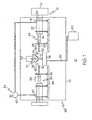
FIG. 1 is a schematical illustration of a reduced mist laser shock peening chamber. -
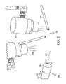
FIG. 2 is an enlarged view of a laser tube aperture and gas knives in the laser shock peening chamber illustrated inFIG. 1 . -
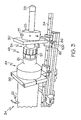
FIG. 3 is an enlarged view of a reducing and telescoping section of the laser tube illustrated inFIG. 1 . -
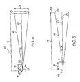
FIG. 4 is a diagrammatical illustration of a steep angle laser beam used in the reduced mist laser shock peening chamber illustrated inFIG. 1 . -
FIG. 5 is an enlarged view of the steep angle laser beam illustrated inFIG. 1 between a focal point of the laser beam and an aperture of the laser tube. - Illustrated in
FIG. 1 is an exemplary embodiment of ashock peening apparatus 10 for laser shock peening a lasershock peening surface 11 of an article or workpiece illustrated by a gas turbine engine blade 8 mounted in a multi-axis computer numerically controlled (CNC)manipulator 127. Theshock peening apparatus 10 is used in conjunction with a laser shock peening cell 68 having anenclosure 70 and a lasershock peening area 72 within the enclosure. The workpiece and multi-axis computer numerically controlled (CNC)manipulator 127 are located within theenclosure 70. - The laser
shock peening apparatus 10 includes alaser unit 12 having a laser beam source 14 for generating alaser beam 16 along alaser beam centerline 20. The exemplary embodiment of the cell 68 has the laser beam source 14 located outside of theenclosure 70 though it need not be. Abeam tube 22 surrounds at least aportion 24 of thebeam centerline 20 and is aimed to pass through abeam aperture 26 located at anexit 28 of thebeam tube 22. Theaperture 26 is illustrated in more detail inFIG. 2 . Afluid nozzle 74 is located proximate to and directed towards the lasershock peening area 72. Typically, the fluid used is water and thefluid nozzle 74 is used to flow a curtain of flowing water onto the lasershock peening surface 11 of the workpiece as illustrated in more detail inFIG. 2 . - Referring to
FiG. 1 , the exemplary embodiment of the apparatus includes a final beamoptical lens 30 mounted within thebeam tube 22 upstream of theaperture 26. A gas purging means 34flows purge gas 35 into thetube 22 between the final beamoptical lens 30 and theaperture 26. The gas purging means 34 illustrated herein includes apurge gas inlet 40 disposed though thetube 22 between the final beamoptical lens 30 and theaperture 26 and apurge gas supply 42 hooked up to the purge gas inlet. Two particularly useful types of thepurge gas 35 are air and Nitrogen. - A
converging section 48 of thetube 22 is located between the final beamoptical lens 30 and theaperture 26. The tube converges in adownstream direction 50 from the final beamoptical lens 30 towards theaperture 26. This forms anair nozzle 84 which tends to prevent blast debris and mist from the laser shock peening from entering thebeam tube 22. Further referring toFIG. 3 , thebeam tube 22 has at least onetelescoping section 54 between the final beamoptical lens 30 and theaperture 26 in order to adjust the distance from the aperture to the lasershock peening area 72. Thetelescoping section 54 is in the convergingsection 48 of thebeam tube 22. Atelescoping knob 57 is used to adjust the tension between first andsecond telescoping elements telescoping section 54. Thebeam tube 22 is supported within theenclosure 70 onframes 90 havingadjustable slides 92 riding onrails 94. Set screws 96 havinglarge knobs 100 for tightening are used to fix the extension of the first andsecond telescoping elements beam tube 22 in place. - Referring to
FIG. 4 , a focal length FL of thelaser beam 16 from the final beamoptical lens 30 to a focal point FP of thelaser beam 16. Typically, thelaser beam 16 defocused + or - a few mils, indicted by a defocus distance DD so that the focal point FP is + or - a few mils behind or in front of lasershock peening surface 11 with respect to the final beamoptical lens 30. In the exemplary embodiment of theapparatus 10, the final beamoptical lens 30 has a focal number FN less than 8. The focal number is defined as a ratio of a focal length FL of the final beamoptical lens 30 to a diameter D of the final beamoptical lens 30. The final beamoptical lens 30 has a focal point FP located past thebeam aperture 26 outside of thebeam tube 22. More particular embodiments of theapparatus 10 have a focal number FN less than 7 and in some embodiments about 5. - The smaller the focal number FN the larger or steeper the focal angle A of the
laser beam 16. The focal angle A is a half angle of the angle of a cone defined by the outer conical surface of the laser beam. Plumes emanate or erupt from the plasma and shock waves generated by the laser shock peening of the lasershock peening surface 11 of the article being laser shock peened. A low focal number FN and corresponding steep focal angle A results in a reduction in length of the plume that is created before the laser beam reaches its focal point or the lasershock peening surface 11. Plumes are very susceptible to mist ionization and, therefore, by reducing the focal number FN, the likelihood of ionization is also reduced. - In one example the
aperture 26 is about one eighth of an inch wide and thelens 30 is about four inches wide. A four inch wide lens having a focal number FN = 9.85 and a focal length FL = 1 meter, and a focal angle A = 2.9 degrees, produces a plume having a plume length = .748 inches. A four inch wide lens having a focal number FN = 7.4 and a focal length FL = .75 meter, and a focal angle A = 3.88 degrees, produces a plume having a plume length = .561 inches. Thus reducing the focal length by 25 percent also reduces the plume length by 25 percent. These numbers in this example are based on empirical data measured in tests. - The exemplary embodiment of the
apparatus 10 further includes agas knife 60 located between theaperture 26 and the focal point FP of thelens 30 as illustrated inFIGS. 1 and2 . Thegas knife 60 is used for flowing a large volume of clearinggas 64 across the laser beam between the aperture and the focal point. Thefluid nozzle 74 is located proximate to and directed towards the lasershock peening area 72. The water from thefluid nozzle 74 is caught in adrain catch 76 located within theenclosure 70 under the lasershock peening area 72. Afluid receptacle 80, such as a tank, is located outside theenclosure 70 and avacuum line 82 leads from thedrain catch 76 to thefluid receptacle 80 for draining liquid runoff from thefluid nozzle 74 in theopen drain catch 76 into thefluid receptacle 80. A source of vacuum is located between theopen drain catch 76 and thefluid receptacle 80. Thefluid receptacle 80 may be maintained at a lower pressure than ambient within theenclosure 70. This helps reduce moisture and mist in the cell andenclosure 70 which in turn reduces mist ionization and ionization of the laser beam before it reaches the work piece. This in turn prevents successive laser beam shots to bloom which interferes with the laser shock peening process and, thus, the reduction of mist and ionization reduces or eliminates loss of efficacy of each successive laser beam shot.
Claims (3)
- A laser shock peening cell (68) comprising:an enclosure and a laser shock peening area (72) within the enclosure (70),a laser unit (12) having a laser beam source (14) for generating a laser beam (16) along a beam centerline (20) across the laser shock peening area (72),a beam tube (22) surrounding at least a portion of the beam centerline (20) and extending at least partially into the enclosure (70),a beam aperture (26) located at an exit of the beam tube (22) proximate the laser shock peening area (72),a final beam optical lens (30) mounted within the tube upstream of the aperture (26),a fluid nozzle (74) directed towards the laser shock peening area (72),
characterized by further comprising :a drain catch (76) located within the enclosure (70) under the laser shock peening area (72),a fluid receptacle (80) located outside the enclosure (70), anda vacuum line (82) between the drain catch (76) and the fluid receptacle (80). - An apparatus as claimed in claim 1 further comprising a gas purging means (34) for flowing a purge gas (35) into the tube between the final beam optical lens (30) and the aperture (26).
- An apparatus as claimed in claim 2 wherein the gas purging means (34) includes a purge gas (35) inlet disposed though the tube between the final beam optical lens (30) and the aperture (26) and a purge gas supply (42) hooked up to the purge gas inlet (40).
Applications Claiming Priority (2)
| Application Number | Priority Date | Filing Date | Title |
|---|---|---|---|
| US448966 | 2003-05-30 | ||
| US10/448,966 US6713716B1 (en) | 2003-05-30 | 2003-05-30 | Reduced mist laser shock peening |
Publications (2)
| Publication Number | Publication Date |
|---|---|
| EP1481753A1 EP1481753A1 (en) | 2004-12-01 |
| EP1481753B1 true EP1481753B1 (en) | 2011-08-03 |
Family
ID=31994385
Family Applications (1)
| Application Number | Title | Priority Date | Filing Date |
|---|---|---|---|
| EP04253141A Expired - Lifetime EP1481753B1 (en) | 2003-05-30 | 2004-05-27 | Reduced mist laser shock peening |
Country Status (4)
| Country | Link |
|---|---|
| US (1) | US6713716B1 (en) |
| EP (1) | EP1481753B1 (en) |
| JP (1) | JP4656861B2 (en) |
| CN (1) | CN100406586C (en) |
Families Citing this family (13)
| Publication number | Priority date | Publication date | Assignee | Title |
|---|---|---|---|---|
| JP2006061966A (en) * | 2004-08-30 | 2006-03-09 | Japan Atom Energy Res Inst | Method of preventing stress corrosion cracking associated with cold working of steel and alloy steel including stainless steel using fs (femtosecond) ultrashort pulse kW class high average power laser |
| JP5552242B2 (en) * | 2008-02-25 | 2014-07-16 | 住友電気工業株式会社 | Surface modification method |
| CN102199769B (en) * | 2011-05-11 | 2013-06-19 | 江苏大学 | Method and apparatus for acquiring nano-coating by utilizing shock waves generated by laser-induced continuous detonation |
| CN102251241A (en) * | 2011-06-24 | 2011-11-23 | 江苏大学 | Method and apparatus for micro-nano particle implanting with laser shockwave induction |
| CN102409156B (en) * | 2011-11-17 | 2014-06-25 | 江苏大学 | Micro-porous member strengthening method for hollow laser-induced shock wave |
| CN103722291B (en) * | 2014-01-02 | 2015-09-02 | 江苏大学 | The continuously adjustable laser-impact welder of angle of attack under a kind of vacuum environment |
| JP6121924B2 (en) * | 2014-02-20 | 2017-04-26 | 株式会社東芝 | Laser processing apparatus and laser processing method |
| CN104357648B (en) * | 2014-10-13 | 2017-04-05 | 中国航空工业集团公司北京航空制造工程研究所 | A kind of laser shock peening method and device |
| DE102016103578B4 (en) * | 2016-02-29 | 2021-08-12 | Gehring Technologies Gmbh + Co. Kg | Device and method for roughening substrates |
| CN108546819A (en) * | 2018-07-19 | 2018-09-18 | 西安天瑞达光电技术股份有限公司 | Between a kind of laser impact intensified processing |
| CN110079659A (en) * | 2019-05-07 | 2019-08-02 | 中山市镭通激光科技有限公司 | A Laser Shock Hardening Method for Metals |
| US12258643B2 (en) * | 2020-03-30 | 2025-03-25 | Airbus Sas | Laser shock peening apparatus |
| CN116393829B (en) * | 2023-04-19 | 2026-03-03 | 江苏大学 | Double-sided laser shot blasting accumulation forming device and method |
Family Cites Families (14)
| Publication number | Priority date | Publication date | Assignee | Title |
|---|---|---|---|---|
| US3850698A (en) * | 1972-06-23 | 1974-11-26 | Ind Materials Ltd | Altering material properties |
| US4401477A (en) * | 1982-05-17 | 1983-08-30 | Battelle Development Corporation | Laser shock processing |
| US4937421A (en) * | 1989-07-03 | 1990-06-26 | General Electric Company | Laser peening system and method |
| DK0510124T3 (en) * | 1990-01-11 | 1995-09-18 | Battelle Memorial Institute | Improving material properties |
| US5932120A (en) * | 1997-12-18 | 1999-08-03 | General Electric Company | Laser shock peening using low energy laser |
| US6259055B1 (en) * | 1998-10-26 | 2001-07-10 | Lsp Technologies, Inc. | Apodizers for laser peening systems |
| US6373876B1 (en) * | 1998-10-26 | 2002-04-16 | Lsp Technologies, Inc. | Single mode oscillator for a laser peening laser |
| US6288358B1 (en) * | 1998-12-15 | 2001-09-11 | Lsp Technologies, Inc. | Mobile laser peening system |
| US6197133B1 (en) * | 1999-02-16 | 2001-03-06 | General Electric Company | Short-pulse high-peak laser shock peening |
| US6359257B1 (en) * | 1999-02-19 | 2002-03-19 | Lsp Technologies, Inc. | Beam path clearing for laser peening |
| US6333488B1 (en) * | 1999-08-30 | 2001-12-25 | General Electric Company | Method for setting up and controlling confinement media flow in laser shock peening |
| US6541733B1 (en) | 2001-01-29 | 2003-04-01 | General Electric Company | Laser shock peening integrally bladed rotor blade edges |
| JP4490608B2 (en) | 2001-08-09 | 2010-06-30 | 株式会社東芝 | Repair method of structure |
| US6818854B2 (en) * | 2001-09-14 | 2004-11-16 | The Regents Of The University Of California | Laser peening with fiber optic delivery |
-
2003
- 2003-05-30 US US10/448,966 patent/US6713716B1/en not_active Expired - Fee Related
-
2004
- 2004-05-27 EP EP04253141A patent/EP1481753B1/en not_active Expired - Lifetime
- 2004-05-28 JP JP2004158510A patent/JP4656861B2/en not_active Expired - Fee Related
- 2004-05-28 CN CNB2004100474964A patent/CN100406586C/en not_active Expired - Fee Related
Also Published As
| Publication number | Publication date |
|---|---|
| CN1572891A (en) | 2005-02-02 |
| US6713716B1 (en) | 2004-03-30 |
| CN100406586C (en) | 2008-07-30 |
| EP1481753A1 (en) | 2004-12-01 |
| JP2004360072A (en) | 2004-12-24 |
| JP4656861B2 (en) | 2011-03-23 |
Similar Documents
| Publication | Publication Date | Title |
|---|---|---|
| US6713716B1 (en) | Reduced mist laser shock peening | |
| US5744781A (en) | Method and apparatus for laser shock peening | |
| US6005219A (en) | Ripstop laser shock peening | |
| US5932120A (en) | Laser shock peening using low energy laser | |
| EP1905852B1 (en) | Varying fluence as a function of thickness during laser shock peening | |
| EP2986410B1 (en) | Process diagnostic system for and method of performing laser shock peening on a target with a fluid flow path sandwiched beteen a transparent to laser light solid medium and the target | |
| EP1852515B1 (en) | LSP on the fly energy change | |
| US6570125B2 (en) | Simultaneous offset dual sided laser shock peening with oblique angle laser beams | |
| JP5403929B2 (en) | Method for machining a feature in a laser shock peened region | |
| US6159619A (en) | Ripstop laser shock peening | |
| KR19990028392A (en) | Laser impact peening method for metal workpieces | |
| US6296448B1 (en) | Simultaneous offset dual sided laser shock peening | |
| EP1288318B1 (en) | Simultaneous offset dual sided laser shock peening using low energy laser beams | |
| US7304266B2 (en) | Laser shock peening coating with entrapped confinement medium | |
| US7097720B2 (en) | Lower fluence boundary laser shock peening | |
| US6559415B1 (en) | Single sided laser shock peening | |
| US6917012B2 (en) | Reducing electromagnetic feedback during laser shock peening | |
| EP1577403A1 (en) | Lower fluence boundary oblique laser shock peening |
Legal Events
| Date | Code | Title | Description |
|---|---|---|---|
| PUAI | Public reference made under article 153(3) epc to a published international application that has entered the european phase |
Free format text: ORIGINAL CODE: 0009012 |
|
| AK | Designated contracting states |
Kind code of ref document: A1 Designated state(s): AT BE BG CH CY CZ DE DK EE ES FI FR GB GR HU IE IT LI LU MC NL PL PT RO SE SI SK TR |
|
| AX | Request for extension of the european patent |
Extension state: AL HR LT LV MK |
|
| 17P | Request for examination filed |
Effective date: 20050601 |
|
| AKX | Designation fees paid |
Designated state(s): DE FR GB IT |
|
| GRAP | Despatch of communication of intention to grant a patent |
Free format text: ORIGINAL CODE: EPIDOSNIGR1 |
|
| GRAS | Grant fee paid |
Free format text: ORIGINAL CODE: EPIDOSNIGR3 |
|
| GRAA | (expected) grant |
Free format text: ORIGINAL CODE: 0009210 |
|
| AK | Designated contracting states |
Kind code of ref document: B1 Designated state(s): DE FR GB IT |
|
| REG | Reference to a national code |
Ref country code: GB Ref legal event code: FG4D |
|
| REG | Reference to a national code |
Ref country code: DE Ref legal event code: R096 Ref document number: 602004033745 Country of ref document: DE Effective date: 20110929 |
|
| PLBE | No opposition filed within time limit |
Free format text: ORIGINAL CODE: 0009261 |
|
| STAA | Information on the status of an ep patent application or granted ep patent |
Free format text: STATUS: NO OPPOSITION FILED WITHIN TIME LIMIT |
|
| 26N | No opposition filed |
Effective date: 20120504 |
|
| REG | Reference to a national code |
Ref country code: DE Ref legal event code: R097 Ref document number: 602004033745 Country of ref document: DE Effective date: 20120504 |
|
| REG | Reference to a national code |
Ref country code: FR Ref legal event code: PLFP Year of fee payment: 12 |
|
| PGFP | Annual fee paid to national office [announced via postgrant information from national office to epo] |
Ref country code: GB Payment date: 20150527 Year of fee payment: 12 Ref country code: DE Payment date: 20150528 Year of fee payment: 12 |
|
| PGFP | Annual fee paid to national office [announced via postgrant information from national office to epo] |
Ref country code: FR Payment date: 20150519 Year of fee payment: 12 Ref country code: IT Payment date: 20150527 Year of fee payment: 12 |
|
| REG | Reference to a national code |
Ref country code: DE Ref legal event code: R119 Ref document number: 602004033745 Country of ref document: DE |
|
| GBPC | Gb: european patent ceased through non-payment of renewal fee |
Effective date: 20160527 |
|
| PG25 | Lapsed in a contracting state [announced via postgrant information from national office to epo] |
Ref country code: IT Free format text: LAPSE BECAUSE OF NON-PAYMENT OF DUE FEES Effective date: 20160527 |
|
| REG | Reference to a national code |
Ref country code: FR Ref legal event code: ST Effective date: 20170131 |
|
| PG25 | Lapsed in a contracting state [announced via postgrant information from national office to epo] |
Ref country code: FR Free format text: LAPSE BECAUSE OF NON-PAYMENT OF DUE FEES Effective date: 20160531 Ref country code: DE Free format text: LAPSE BECAUSE OF NON-PAYMENT OF DUE FEES Effective date: 20161201 |
|
| PG25 | Lapsed in a contracting state [announced via postgrant information from national office to epo] |
Ref country code: GB Free format text: LAPSE BECAUSE OF NON-PAYMENT OF DUE FEES Effective date: 20160527 |