EP1480746B1 - A reactive distillation alkylation process including in situ catalyst regeneration - Google Patents
A reactive distillation alkylation process including in situ catalyst regeneration Download PDFInfo
- Publication number
- EP1480746B1 EP1480746B1 EP03703858A EP03703858A EP1480746B1 EP 1480746 B1 EP1480746 B1 EP 1480746B1 EP 03703858 A EP03703858 A EP 03703858A EP 03703858 A EP03703858 A EP 03703858A EP 1480746 B1 EP1480746 B1 EP 1480746B1
- Authority
- EP
- European Patent Office
- Prior art keywords
- catalyst
- zone
- paraffin
- column
- benzene
- Prior art date
- Legal status (The legal status is an assumption and is not a legal conclusion. Google has not performed a legal analysis and makes no representation as to the accuracy of the status listed.)
- Expired - Lifetime
Links
- 239000003054 catalyst Substances 0.000 title claims abstract description 110
- 238000011069 regeneration method Methods 0.000 title claims abstract description 63
- 230000008929 regeneration Effects 0.000 title claims abstract description 61
- 238000005804 alkylation reaction Methods 0.000 title claims abstract description 45
- 238000000066 reactive distillation Methods 0.000 title claims abstract description 26
- 238000011065 in-situ storage Methods 0.000 title abstract description 6
- 239000012188 paraffin wax Substances 0.000 claims abstract description 75
- 238000010992 reflux Methods 0.000 claims abstract description 58
- 150000001336 alkenes Chemical class 0.000 claims abstract description 54
- 150000004945 aromatic hydrocarbons Chemical class 0.000 claims abstract description 50
- 238000000034 method Methods 0.000 claims abstract description 34
- 230000008569 process Effects 0.000 claims abstract description 33
- 230000029936 alkylation Effects 0.000 claims abstract description 32
- 238000006243 chemical reaction Methods 0.000 claims abstract description 19
- 238000004821 distillation Methods 0.000 claims abstract description 19
- 239000006227 byproduct Substances 0.000 claims abstract description 11
- 239000011973 solid acid Substances 0.000 claims abstract description 11
- JRZJOMJEPLMPRA-UHFFFAOYSA-N olefin Natural products CCCCCCCC=C JRZJOMJEPLMPRA-UHFFFAOYSA-N 0.000 claims description 46
- UHOVQNZJYSORNB-UHFFFAOYSA-N Benzene Chemical compound C1=CC=CC=C1 UHOVQNZJYSORNB-UHFFFAOYSA-N 0.000 abstract description 274
- 238000002347 injection Methods 0.000 abstract description 38
- 239000007924 injection Substances 0.000 abstract description 38
- 150000001491 aromatic compounds Chemical class 0.000 abstract description 12
- 125000003118 aryl group Chemical group 0.000 abstract description 9
- 230000000737 periodic effect Effects 0.000 abstract description 3
- 239000000203 mixture Substances 0.000 description 18
- 238000004088 simulation Methods 0.000 description 17
- 239000007791 liquid phase Substances 0.000 description 15
- 239000000047 product Substances 0.000 description 14
- 239000007788 liquid Substances 0.000 description 12
- 239000002585 base Substances 0.000 description 10
- 239000010457 zeolite Substances 0.000 description 8
- WKBOTKDWSSQWDR-UHFFFAOYSA-N Bromine atom Chemical compound [Br] WKBOTKDWSSQWDR-UHFFFAOYSA-N 0.000 description 7
- GDTBXPJZTBHREO-UHFFFAOYSA-N bromine Substances BrBr GDTBXPJZTBHREO-UHFFFAOYSA-N 0.000 description 7
- 229910052794 bromium Inorganic materials 0.000 description 7
- 241000183024 Populus tremula Species 0.000 description 6
- 125000004432 carbon atom Chemical group C* 0.000 description 6
- RWGFKTVRMDUZSP-UHFFFAOYSA-N cumene Chemical compound CC(C)C1=CC=CC=C1 RWGFKTVRMDUZSP-UHFFFAOYSA-N 0.000 description 6
- 238000003860 storage Methods 0.000 description 6
- 230000008901 benefit Effects 0.000 description 5
- 229910052799 carbon Inorganic materials 0.000 description 5
- 230000009849 deactivation Effects 0.000 description 5
- 238000012856 packing Methods 0.000 description 5
- 230000032258 transport Effects 0.000 description 5
- VSCWAEJMTAWNJL-UHFFFAOYSA-K aluminium trichloride Chemical compound Cl[Al](Cl)Cl VSCWAEJMTAWNJL-UHFFFAOYSA-K 0.000 description 4
- 239000003599 detergent Substances 0.000 description 4
- OKTJSMMVPCPJKN-UHFFFAOYSA-N Carbon Chemical compound [C] OKTJSMMVPCPJKN-UHFFFAOYSA-N 0.000 description 3
- YXFVVABEGXRONW-UHFFFAOYSA-N Toluene Chemical compound CC1=CC=CC=C1 YXFVVABEGXRONW-UHFFFAOYSA-N 0.000 description 3
- 229910021536 Zeolite Inorganic materials 0.000 description 3
- 230000015556 catabolic process Effects 0.000 description 3
- 238000006731 degradation reaction Methods 0.000 description 3
- 230000000694 effects Effects 0.000 description 3
- 238000005516 engineering process Methods 0.000 description 3
- 239000002808 molecular sieve Substances 0.000 description 3
- 229910052680 mordenite Inorganic materials 0.000 description 3
- 230000009467 reduction Effects 0.000 description 3
- URGAHOPLAPQHLN-UHFFFAOYSA-N sodium aluminosilicate Chemical compound [Na+].[Al+3].[O-][Si]([O-])=O.[O-][Si]([O-])=O URGAHOPLAPQHLN-UHFFFAOYSA-N 0.000 description 3
- 239000011949 solid catalyst Substances 0.000 description 3
- IJGRMHOSHXDMSA-UHFFFAOYSA-N Atomic nitrogen Chemical compound N#N IJGRMHOSHXDMSA-UHFFFAOYSA-N 0.000 description 2
- KRHYYFGTRYWZRS-UHFFFAOYSA-N Fluorane Chemical compound F KRHYYFGTRYWZRS-UHFFFAOYSA-N 0.000 description 2
- ISWSIDIOOBJBQZ-UHFFFAOYSA-N Phenol Chemical compound OC1=CC=CC=C1 ISWSIDIOOBJBQZ-UHFFFAOYSA-N 0.000 description 2
- NBIIXXVUZAFLBC-UHFFFAOYSA-N Phosphoric acid Chemical compound OP(O)(O)=O NBIIXXVUZAFLBC-UHFFFAOYSA-N 0.000 description 2
- PPBRXRYQALVLMV-UHFFFAOYSA-N Styrene Chemical compound C=CC1=CC=CC=C1 PPBRXRYQALVLMV-UHFFFAOYSA-N 0.000 description 2
- 239000002253 acid Substances 0.000 description 2
- PNEYBMLMFCGWSK-UHFFFAOYSA-N aluminium oxide Inorganic materials [O-2].[O-2].[O-2].[Al+3].[Al+3] PNEYBMLMFCGWSK-UHFFFAOYSA-N 0.000 description 2
- 238000004458 analytical method Methods 0.000 description 2
- 230000003197 catalytic effect Effects 0.000 description 2
- 238000006356 dehydrogenation reaction Methods 0.000 description 2
- 238000010438 heat treatment Methods 0.000 description 2
- 229930195733 hydrocarbon Natural products 0.000 description 2
- 150000002430 hydrocarbons Chemical class 0.000 description 2
- 239000012263 liquid product Substances 0.000 description 2
- 239000000463 material Substances 0.000 description 2
- 238000002156 mixing Methods 0.000 description 2
- 239000002574 poison Substances 0.000 description 2
- 231100000614 poison Toxicity 0.000 description 2
- 238000011084 recovery Methods 0.000 description 2
- 239000007787 solid Substances 0.000 description 2
- 230000007704 transition Effects 0.000 description 2
- 238000005406 washing Methods 0.000 description 2
- 239000004215 Carbon black (E152) Substances 0.000 description 1
- CTQNGGLPUBDAKN-UHFFFAOYSA-N O-Xylene Chemical compound CC1=CC=CC=C1C CTQNGGLPUBDAKN-UHFFFAOYSA-N 0.000 description 1
- 230000002378 acidificating effect Effects 0.000 description 1
- 230000009471 action Effects 0.000 description 1
- 150000001335 aliphatic alkanes Chemical class 0.000 description 1
- 150000004996 alkyl benzenes Chemical class 0.000 description 1
- 229940100198 alkylating agent Drugs 0.000 description 1
- 239000002168 alkylating agent Substances 0.000 description 1
- 230000002152 alkylating effect Effects 0.000 description 1
- 229910000147 aluminium phosphate Inorganic materials 0.000 description 1
- XDLDASNSMGOEMX-UHFFFAOYSA-N benzene benzene Chemical compound C1=CC=CC=C1.C1=CC=CC=C1 XDLDASNSMGOEMX-UHFFFAOYSA-N 0.000 description 1
- 238000009835 boiling Methods 0.000 description 1
- 238000003965 capillary gas chromatography Methods 0.000 description 1
- 238000003442 catalytic alkylation reaction Methods 0.000 description 1
- 238000006555 catalytic reaction Methods 0.000 description 1
- 238000004891 communication Methods 0.000 description 1
- 238000009833 condensation Methods 0.000 description 1
- 230000005494 condensation Effects 0.000 description 1
- 238000010924 continuous production Methods 0.000 description 1
- 230000008878 coupling Effects 0.000 description 1
- 238000010168 coupling process Methods 0.000 description 1
- 238000005859 coupling reaction Methods 0.000 description 1
- 230000003247 decreasing effect Effects 0.000 description 1
- GUJOJGAPFQRJSV-UHFFFAOYSA-N dialuminum;dioxosilane;oxygen(2-);hydrate Chemical compound O.[O-2].[O-2].[O-2].[Al+3].[Al+3].O=[Si]=O.O=[Si]=O.O=[Si]=O.O=[Si]=O GUJOJGAPFQRJSV-UHFFFAOYSA-N 0.000 description 1
- HNPSIPDUKPIQMN-UHFFFAOYSA-N dioxosilane;oxo(oxoalumanyloxy)alumane Chemical compound O=[Si]=O.O=[Al]O[Al]=O HNPSIPDUKPIQMN-UHFFFAOYSA-N 0.000 description 1
- 238000009826 distribution Methods 0.000 description 1
- SNRUBQQJIBEYMU-UHFFFAOYSA-N dodecane Chemical compound CCCCCCCCCCCC SNRUBQQJIBEYMU-UHFFFAOYSA-N 0.000 description 1
- 239000003623 enhancer Substances 0.000 description 1
- 230000007613 environmental effect Effects 0.000 description 1
- 238000001704 evaporation Methods 0.000 description 1
- 230000008020 evaporation Effects 0.000 description 1
- 239000012467 final product Substances 0.000 description 1
- 239000013067 intermediate product Substances 0.000 description 1
- 238000004519 manufacturing process Methods 0.000 description 1
- 238000012544 monitoring process Methods 0.000 description 1
- 229910052901 montmorillonite Inorganic materials 0.000 description 1
- 229940094933 n-dodecane Drugs 0.000 description 1
- 229910052757 nitrogen Inorganic materials 0.000 description 1
- TVMXDCGIABBOFY-UHFFFAOYSA-N octane Chemical compound CCCCCCCC TVMXDCGIABBOFY-UHFFFAOYSA-N 0.000 description 1
- -1 olefin compound Chemical class 0.000 description 1
- 239000011148 porous material Substances 0.000 description 1
- 238000002360 preparation method Methods 0.000 description 1
- 230000002035 prolonged effect Effects 0.000 description 1
- QQONPFPTGQHPMA-UHFFFAOYSA-N propylene Natural products CC=C QQONPFPTGQHPMA-UHFFFAOYSA-N 0.000 description 1
- 125000004805 propylene group Chemical group [H]C([H])([H])C([H])([*:1])C([H])([H])[*:2] 0.000 description 1
- 229910052761 rare earth metal Inorganic materials 0.000 description 1
- 150000002910 rare earth metals Chemical group 0.000 description 1
- 230000007420 reactivation Effects 0.000 description 1
- 230000011514 reflex Effects 0.000 description 1
- 230000000630 rising effect Effects 0.000 description 1
- 238000000926 separation method Methods 0.000 description 1
- 239000004094 surface-active agent Substances 0.000 description 1
- 238000013022 venting Methods 0.000 description 1
- 239000008096 xylene Substances 0.000 description 1
Images




Classifications
-
- B—PERFORMING OPERATIONS; TRANSPORTING
- B01—PHYSICAL OR CHEMICAL PROCESSES OR APPARATUS IN GENERAL
- B01J—CHEMICAL OR PHYSICAL PROCESSES, e.g. CATALYSIS OR COLLOID CHEMISTRY; THEIR RELEVANT APPARATUS
- B01J29/00—Catalysts comprising molecular sieves
- B01J29/90—Regeneration or reactivation
-
- B—PERFORMING OPERATIONS; TRANSPORTING
- B01—PHYSICAL OR CHEMICAL PROCESSES OR APPARATUS IN GENERAL
- B01J—CHEMICAL OR PHYSICAL PROCESSES, e.g. CATALYSIS OR COLLOID CHEMISTRY; THEIR RELEVANT APPARATUS
- B01J38/00—Regeneration or reactivation of catalysts, in general
- B01J38/48—Liquid treating or treating in liquid phase, e.g. dissolved or suspended
- B01J38/50—Liquid treating or treating in liquid phase, e.g. dissolved or suspended using organic liquids
-
- B—PERFORMING OPERATIONS; TRANSPORTING
- B01—PHYSICAL OR CHEMICAL PROCESSES OR APPARATUS IN GENERAL
- B01D—SEPARATION
- B01D3/00—Distillation or related exchange processes in which liquids are contacted with gaseous media, e.g. stripping
- B01D3/009—Distillation or related exchange processes in which liquids are contacted with gaseous media, e.g. stripping in combination with chemical reactions
-
- B—PERFORMING OPERATIONS; TRANSPORTING
- B01—PHYSICAL OR CHEMICAL PROCESSES OR APPARATUS IN GENERAL
- B01J—CHEMICAL OR PHYSICAL PROCESSES, e.g. CATALYSIS OR COLLOID CHEMISTRY; THEIR RELEVANT APPARATUS
- B01J38/00—Regeneration or reactivation of catalysts, in general
- B01J38/04—Gas or vapour treating; Treating by using liquids vaporisable upon contacting spent catalyst
- B01J38/12—Treating with free oxygen-containing gas
- B01J38/38—Treating with free oxygen-containing gas and adding heat by solid heat carrier
-
- B—PERFORMING OPERATIONS; TRANSPORTING
- B01—PHYSICAL OR CHEMICAL PROCESSES OR APPARATUS IN GENERAL
- B01J—CHEMICAL OR PHYSICAL PROCESSES, e.g. CATALYSIS OR COLLOID CHEMISTRY; THEIR RELEVANT APPARATUS
- B01J38/00—Regeneration or reactivation of catalysts, in general
- B01J38/48—Liquid treating or treating in liquid phase, e.g. dissolved or suspended
- B01J38/50—Liquid treating or treating in liquid phase, e.g. dissolved or suspended using organic liquids
- B01J38/56—Hydrocarbons
-
- C—CHEMISTRY; METALLURGY
- C07—ORGANIC CHEMISTRY
- C07C—ACYCLIC OR CARBOCYCLIC COMPOUNDS
- C07C2/00—Preparation of hydrocarbons from hydrocarbons containing a smaller number of carbon atoms
- C07C2/54—Preparation of hydrocarbons from hydrocarbons containing a smaller number of carbon atoms by addition of unsaturated hydrocarbons to saturated hydrocarbons or to hydrocarbons containing a six-membered aromatic ring with no unsaturation outside the aromatic ring
- C07C2/64—Addition to a carbon atom of a six-membered aromatic ring
- C07C2/66—Catalytic processes
-
- C—CHEMISTRY; METALLURGY
- C07—ORGANIC CHEMISTRY
- C07C—ACYCLIC OR CARBOCYCLIC COMPOUNDS
- C07C5/00—Preparation of hydrocarbons from hydrocarbons containing the same number of carbon atoms
- C07C5/22—Preparation of hydrocarbons from hydrocarbons containing the same number of carbon atoms by isomerisation
-
- Y—GENERAL TAGGING OF NEW TECHNOLOGICAL DEVELOPMENTS; GENERAL TAGGING OF CROSS-SECTIONAL TECHNOLOGIES SPANNING OVER SEVERAL SECTIONS OF THE IPC; TECHNICAL SUBJECTS COVERED BY FORMER USPC CROSS-REFERENCE ART COLLECTIONS [XRACs] AND DIGESTS
- Y02—TECHNOLOGIES OR APPLICATIONS FOR MITIGATION OR ADAPTATION AGAINST CLIMATE CHANGE
- Y02P—CLIMATE CHANGE MITIGATION TECHNOLOGIES IN THE PRODUCTION OR PROCESSING OF GOODS
- Y02P20/00—Technologies relating to chemical industry
- Y02P20/10—Process efficiency
-
- Y—GENERAL TAGGING OF NEW TECHNOLOGICAL DEVELOPMENTS; GENERAL TAGGING OF CROSS-SECTIONAL TECHNOLOGIES SPANNING OVER SEVERAL SECTIONS OF THE IPC; TECHNICAL SUBJECTS COVERED BY FORMER USPC CROSS-REFERENCE ART COLLECTIONS [XRACs] AND DIGESTS
- Y02—TECHNOLOGIES OR APPLICATIONS FOR MITIGATION OR ADAPTATION AGAINST CLIMATE CHANGE
- Y02P—CLIMATE CHANGE MITIGATION TECHNOLOGIES IN THE PRODUCTION OR PROCESSING OF GOODS
- Y02P20/00—Technologies relating to chemical industry
- Y02P20/50—Improvements relating to the production of bulk chemicals
- Y02P20/584—Recycling of catalysts
Definitions
- This invention relates to catalyst regeneration. More particularly, this invention relates to the in situ regeneration of solid acid catalysts in a unified continuous, pressurized, reactive distillation process for the alkylation of light aromatic compounds, such as benzene and cumene.
- alkylation of aromatic compounds with olefins is an established commercial technology.
- benzene alkylated with short chain (typically 2 to about 6 carbons) hydrocarbons has value as gasoline octane enhancer.
- Light aromatic compounds alkylated with longer chain (that is, having greater than about 8-10 carbon atoms) linear olefins are commonly sulfonated to produce surfactants suitable for use in detergent manufacture.
- alkylation of benzene and other light aromatic compounds has typically been carried out using hydrofluoric acid or a solid acid catalyst in a fixed bed, plug flow process.
- hydrofluoric acid or a solid acid catalyst in a fixed bed, plug flow process.
- U.S. Patent No. 2,860,173 discloses the use of a solid phosphoric acid as a catalyst for the alkylation of benzene with propylene to produce cumene.
- Friedel Crafts catalysts especially aluminum chloride and certain natural zeolites and synthetic commercial sieves, as alkylation catalysts, has been taught.
- 5,770,782 used a 5/1 to 20/1 benzene/olefin mole ratio for the co-fed mixture and indicate a need for mechanical mixing of the aromatic and olefin before they enter the catalyst bed to assure adequate conversion and alkylated yield.
- WO 01/83408 A1 discloses a process for the alkylating an alkylatable aromatic compound by (a) contacting an alkylatable aromatic compound and an alkylating agent with an alkylation catalyst under alkylation conditions and (b) contacting said alkylation catalyst with a C1 - C8 hydrocarbon, preferably an alkane, under alkylation catalyst reactivation conditions, when said alkylation catalyst has become at least partially deactivated.
- EP 0353813 A1 discloses a continuous process for the catalytic alkylation of aromatic hydrocarbons with an olefin compound, which comprises the separation of the resulting alkylation product in an aromatic fraction, a mono alkyl aromatic fraction, a heavy alkyl aromatic fraction and a paraffin fraction, wherein the aromatic and paraffin fractions are recycled to the process.
- the catalyst is cyclically regenerated by alternating and successive washing the catalyst bed with paraffin and other products of different polarity. Said regeneration is carried out a temperature of 150 to 300°C and at a space velocity of 1 to 10 hr -1 .
- This invention provides a unified reactive distillation process and system useful in the preparation of mono-alkylated aromatic compounds by the solid acid-catalyzed reaction of light aromatic compounds with low molecular weight, straight chain olefins, which allows for the periodic in situ regeneration of the catalyst, i.e., in the distillation column.
- the aromatic alkylation process of the invention involves a reactive distillation process and comprises a continuous, pressurized process using a distillation column configuration and system including a reactive zone, a first rectification zone at the top of the distillation column for rectification and recovery of unreacted aromatic hydrocarbon feedstock, an intermediate reactive zone containing a solid acid alkylation catalyst, and a second rectification zone positioned below and in communication with the reactive zone, where unreacted aromatic hydrocarbon and olefin feedstock may be separated from the alkylation product and any by-products.
- a reboiler and means for withdrawing the alkylation product from the column.
- injectors allow for the controlled introduction of aromatic hydrocarbon compound and olefin feedstock.
- At least a portion of a suitable olefin feedstock is introduced at a point between the intermediate catalyst zone and the upper rectification zone, and at least a portion of a suitable aromatic hydrocarbon feedstock is introduced at a point between the catalyst zone and a second, lower, rectification zone, and the aromatic hydrocarbon is refluxed upwardly through the catalyst zone to contact and react with the descending olefin feedstock in a counter-current, liquid phase reaction.
- the conditions of the reaction require that the internal pressure in the reactive zone is maintained constant and above about 101 kPa (1 atmosphere), preferably between about 140 (20) and 1379 kPa (200 psig), and the combination of olefin and aromatic hydrocarbon in the reboiler maintained at or near reflux such that the temperature in the reboiler stays below the thermal degradation temperature for the alkylated product, which is about 265°C, and the molar ratio of the aromatic hydrocarbon to the olefin in the liquid phase can be maintained between about 30/1 to about 100/1, preferably between about 40/1 to about 80/1.
- periodic regeneration of the alkylation catalyst can be accomplished in the distillation column periodically by ceasing flow of the olefin feedstock and injecting an effective amount of a suitable paraffin into the column counter-current to the flow of the aromatic hydrocarbon feedstock and adjusting the internal column pressure and temperature in the catalyst zone to achieve the desired regeneration temperature which, as is well known in this art, is within the range of above about 175°C, generally from about 175°C. to about 250°C.
- the preferred regeneration method of the invention will be to periodically inject the paraffin into the distillation column at a point below the first rectification zone and above the catalyst, whereby the paraffin intermixes with the refluxing aromatic hydrocarbon feedstock in counter-currcnt flow through the catalyst zone and, in combination with the aromatic hydrocarbon, dilutes and dissolves the by-products and other material from the catalyst surface and transports it into the reboiler for recovery and disposal.
- the use of a counter-current flow of paraffin and aromatic hydrocarbon in the column provides an unexpected reduction in the required operating pressure to achieve the desired regeneration temperature in the catalyst zone.
- the process permits regeneration at milder conditions, e.g., 175-250°C, than typically environmental in a fixed bed process.
- the temperature may be adjusted using both the internal pressure of the column and the reflux rate of the aromatic hydrocarbon. For example, at a column pressure of 862 (125) to 2551 kPa (370 psig), a composition of 40-90 mote % aromatic hydrocarbon with paraffin can be employed.
- aromatics or aromatic we mean organic; aromatic compounds having one or more rings and from 6 to about 20 carbon atoms, that boil at or below about 250°C under pressure conditions typical in a commercial reactor-type distillation column.
- the preferred members of this group are benzene, toluene, xylene, styrene, phenol and cumene, with benzene being especially preferred.
- the preferred olefins include those straight chain mono-unsaturated olefins having from 2 to about 30 carbon atoms, preferably from about 8 to about 20 carbon atoms and, more preferably, from 10 to 14 carbon atoms.
- a particularly preferred olefin feedstock for detergent range alkylate comprises a mixture of C 6 -C 18 olefins with C 6 -C 18 paraffins derived from a conunercial paraffin dehydrogenation process.
- paraffins or paraffin feedstock suitable for use in the alkylation catalyst regeneration process of the present invention include paraffins having from C 4 to C 16 carbon atoms. In the case of gasoline range alkylation, paraffins of C 4 to C 16 carbon content, are preferred while in the case of detergent range alkylation, paraffins of C 8 to C 16 carbon content are preferred.
- the catalyst regeneration process of the present invention is conveniently carried out in a unified, continuous, reactive alkylation process such as that disclosed in U.S. Patent 66424425 , filed concurrently herewith and entitled "A Reactive Distillation Process for the Alkylation of Aromatic Hydrocarbons".
- a reactive distillation configuration such as that disclosed in accompanying Fig. 1
- an olefin/paraffin mixture is injected below the benzene rectification zone at the top of the distillation column, but above the catalyst zone.
- the aromatic hydrocarbon is continuously injected at a point below the solid catalyst reactive zone and above a rectification zone, in which it can be separated from the alkylated product, paraffin and unreacted olefin that descends from the reactive zone on its way to the reboiler.
- Catalysts that may be employed for this invention include such acid zeolitic materials as W-Zeolite, beta-zeolite, acidic mordenite, acid days, such as montmorillonite and medium pore zeolites such as ZSM-5, ZSM-12, ZSM-18, ZSM-20, MCM-22, and BETA, L, Y, mordenite, as well as rare earth exchanged forms or de-aluminated forms of the listed zeolites.
- catalysts that may be employed in the practice of this invention are the fluorided versions of the above-mentioned zeolites and aluminum chloride impregnated on alumina, clays and silica-alumina.
- the catalyst can be maintained in place by supporting it on structured packing, such as Koch-Glitch KATAMAX brand catalytic structured packing, or alternatively arranged in other ways familiar to those skilled in this art, for example, in a series of beds on perforated trays or in beds positioned in the liquid down corners of a trayed distillation column.
- structured can also be used in the rectification zones, without catalyst, to improve the evaporation and condensation efficiency in those zones.
- the molar ratio of the aromatic hydrocarbon to the liquid phase olefin in the reactive zone is maintained through adjustment of the column internal back pressure, the aromatic hydrocarbon reflux rate, the energy input into the reboiler, the amount of aromatic hydrocarbon removed while maintaining the column at or approaching total reflux, and the input flow of aromatic hydrocarbon. Coupling the reflux rate of the aromatic hydrocarbon with the relatively low introduction of additional aromatic hydrocarbon into the column will tend to increase the composition of aromatic hydrocarbon refluxing into the reactive zone and keep the molar ratio of the aromatic hydrocarbon to the olefin in the reactive catalyst zone at a higher level.
- Fig. 1 the regeneration process of this invention was carried out in a continuous reactive distillation column depicted in Fig. 1 .
- Fig. 1 for convenience, two separate columns were employed and designed to perform as a single reactive distillation column.
- Differential pressure control established vapor transport between the lower half (column 1) and the upper half (column 2).
- Liquid transport between upper segments (column 2) and lower segments (column 1) was handled by a pump and flow control from the base of column 2.
- the catalysts employed were solid acid mordenite and Y zeolites.
- the catalyst is granulated to a 16 x 40 U.S. mesh size, dried at an appropriate temperature to activate it, and loaded into 54 KATAMAX catalyst packing elements. Each element has a 5 cm (2 inch) outside diameter and is 14 cm (5.5 inches) long.
- the mass of catalyst loaded into the column will depend on its density. However, since each of the KATAMAX elements all had the same internal catalyst volume (50.8cc), the catalyst was equally distributed by using 9 KATAMAX elements in each of Sections B, C, D, E, F, and G as shown in Fig. 1 .
- Transition from detergent range alkylation tu catalyst regeneration is made by stopping the injection of the Q 10 - C 14 paraffin/olefin mixture and replacing it with a C 8 -C 16 paraffin, while maintaining the benzene flow rate and reflux rate at the base of the column.
- In situ counter-current regeneration is achieved by raising the column pressure to between about 862 (125) to 1724 kPa (250 psig) while maintaining the benzene flow at a relatively low rate with high reflux.
- the paraffin is injected from the storage tank 1.
- the paraffin feed is pumped from a storage tank 1 at a controlled, rate using pump 2, Control Valve 3 and mass flow sensor 4.
- the paraffin feed passes through a 4A molecular sieve bed 5 where it is dried, and then through preheater 6, where the temperature is adjusted to match the measured reflux temperature inside the column at the point of injection.
- the temperature is monitored and adjusted upward to match the reflux temperature as the paraffin composition in the column increases.
- the point of paraffin injection is conveniently the same point as the olefin feed, that is, just above the KATAMAX catalyst elements in Section B, which is just below Section A, the rectification zone that separates and refluxes the aromatic hydrocarbon (which, in each of the examples, is benzene).
- Benzene injection temperatures at the base of the column and at the benzene reflux injection point are adjusted upward to match the increase in the reflux temperature as the paraffin content increases.
- the regeneration in this counter-current manner is maintained for about 8 to about 36 hours, depending on such parameters as the type of catalyst being used and the degree to which it became deactivated.
- transition back to the alkylation mode is achieved by stopping the flow of paraffin while maintaining or adjusting the flow of the aromatic hydrocarbon at the base of the catalyst bed to maintain the aromatic hydrocarbon in reflux.
- the column temperature is allowed to cool back to alkylation reaction temperature, while in aromatic hydrocarbon reflux condition. This is accomplished generally by gradually decreasing the column pressure back to the pressure at which the alkylation reaction takes place.
- the refluxing of the aromatic hydrocarbon acts to cool the column relatively quickly.
- olefin feedstock can be re-introduced to once again begin the alkylation process.
- the preferred olefin feed set forth is a paraffin/olefin feedstock derived from a paraffin dehydrogenation process.
- the olcfin/paraffin mixture is pumped from Feed Storage Tank 1 at a controlled rate, is passed through a 4A molecular sieve bed 5 where it is dried, and then through preheater 6, where the temperature is adjusted to match the measured reflux temperature inside the column at the point of injection.
- the injection temperature is monitored and adjusted upward to match the measured reflux temperature inside the distillation column at the point of injection.
- the point of olefin feed injection is just above the KATAMAX catalyst elements in Section B, which is just below Section A, the rectification zone that separates and refluxes the aromatic hydrocarbon (which, in each of the examples, is benzene).
- the aromatic hydrocarbon is pumped from storage tank 11 using pump 12, with flow controlled by control valve 13 and monitored using mass flow meter 14. Prior to injection, the aromatic hydrocarbon is also passed through a molecular sieve dryer 15 and preheater 16 and is heated to about 5-10°C. below its boiling point at the experimental internal column pressure. Thus, it is injected as a liquid, but generally will quickly flash due to the heat from the liquid and vapor rising out of the reboiler. As depicted in Fig. 1 , the injection point 17 of the aromatic hydrocarbon is at the base of Section G, but above the rectification zone (Section H) which is immediately above the reboiler 40. This is the primary injection point and sets up the counter-current flow of aromatic hydrocarbon with the olefin descending as a liquid from its injection point 7 (above the catalyst in Section B).
- a molecular sieve dryer 15 and preheater 16 Prior to injection, the aromatic hydrocarbon is also passed through a molecular sieve dryer 15 and p
- the aromatic hydrocarbon employed in the example was benzene.
- Benzene vapor in the column is taken overhead and condensed in cooler 19 and accumulated in vessel 20.
- the accumulated benzene is reinjected as reflux at point 21 in rectification zone A.
- this can be through level control from the accumulator vessel 20 or on flow control to the column along with a stream that removes excess benzene storage to tank 25 using the appropriate monitoring and flow controlling apparatus.
- the desired operating pressure is adjusted and maintained using cascade control with appropriate nitrogen injection and venting into and out of the accumulator tank 20.
- the two column configuration depicted in the drawing was also used in the example. The two columns were operated as one by means of heaters and flow control valves.
- the benzene vapor, as it leaves Section E and flows between the columns, is maintained at the appropriate temperature and pressure by means of an electrically heated and controlled vapor transport line 26. Benzene vapor enters the base of Section D of the column at point 27 and continues through segments D, C and B.
- the flow between the columns is controlled at control valve 23 using a relatively low differential pressure, usually about 14 kPa (2 psig).
- Sample point A is the final product after passing through all catalyst sections.
- Sample point B is an intermediate product representing 50% of the catalyst residence time.
- a third sample point, not shown, can be at the base of the benzene overhead accumulator 20. This can be used to measure benzene purity.
- a unique feature of the reactive distillation unit of the present invention is the ability to regenerate the catalyst in situ at a set of regeneration conditions that are in general milder then those required to regenerate a plug flow fixed bed catalytic reactor.
- the fixed bed process calls for the use of pure benzene to be maintained in the liquid phase at 3447 kPa (500 psig) and 250°C regeneration temperature.
- Sample point A is cooled liquid product removed from the reboiler and represents the total conversion in the reactive distillation column.
- Sample point B is a cooled liquid sample removed from the intermediate accumulator at the base of column, section D. This sample point represents the conversion at 50% of the catalyst volume.
- the TOSOH 330 Y zeolite solid acid catalyst was operated per the condition shown in Table 2 for a total of 118.5 hours on stream. During this operating period the TOSOH 330 Y experienced significant deactivation.
- the conversion at point B was initially 99.96 % with a residual bromine index in the crude benzene, paraffin/olefin and alkylate product of 1.1 cg/g.
- the catalyst in sections B, C, and D experienced significant deactivation as the conversion dropped to 24.7% (Bromine Index 2185) at 118.5 hours on stream.
- Sections E, F, and G experienced deactivation from 100% conversion (Bromine index non detectable) to 88.8% conversion with a residual bromine index of 829 cg/g.
- the catalyst deactivates from top to bottom in the distillation column. After 118.5 hours on stream, the paraffin/olefin mixture was discontinued and the column refluxed benzene at 134°C for 2 hours as the crude alkylate is washed from the catalyst bed into the reboiler.
- paraffin/olefin feed in the storage tank was replaced with a paraffin feed of the same molecular weight and carbon number distribution as shown in Table 1.
- the column back pressure is increased to 862 kPa (125 psig) and the benzene reflux stabilizes at 862 kPa (125 psig).
- a uniform column temperature of only 172°-175°C is achieved with benzene reflux at 862 kPa (125 psig) back pressure.
- Paraffin injection is initiated at 50 g/min through H101 at a point just above the first section containing the catalyst structured packing.
- the counter-current paraffin injection alters the composition in the column which increases the reflux temperature.
- the counter-current paraffin flow establishes a regeneration temperature profile as shown in Fig.
- paraffin above the catalyst is one means of increasing the steady state regeneration temperature in the reactive distillation column.
- This paraffin injection provides a temperature increase as well as additional washing action to transport the by-products on the catalyst and transfers them to the reboiler.
- This effect of increased regeneration temperature with paraffin injection can be applied at higher pressure and will continue to achieve a stepwise advantage for reaching higher regeneration temperature at a given distillation column pressure.
- This effect can be modeled to determine the extent of the advantage beyond the pressure limit of the experimental reactive distillation column shown in Fig. 1 .
- Table 3 and Fig. 3 compare experimental data at 862 kPa (125 psig), 50 g/min of C 10 -C 13 paraffin injection above the catalyst bed, and 10 g/min.
- the simulation conditions arc identical to the experimental operating conditions with n-dodccane used to simulate the injected paraffin.
- the catalyst bed lies between Stage 6 and 18 for the simulation.
- the 862 kPa (125 psig) pressure range is within the mechanical limit of the reactive distillation column shown in Fig. 1 .
- Fig. 3 shows a good correlation between experimental data and the simulation.
- the advantage of counter-current paraffin injection and benzene at reflux can he shown by further simulations at higher column back pressures.
- Another mode of column operation can also be used to achieve high regeneration temperatures without significant increases in column pressure.
- This mode of operation also uses counter-current paraffin injection at the top of the catalyst bed and injection of benzene below the catalyst but maintained at reflux.
- a significant unexpected advantage from reducing the benzene reflux rate with paraffin injection was observed through ASPEN Simulation.
- Target regeneration temperatures in the range of 200° to 250°C could be achieved by reducing the benzene reflux from 150 g/min down to 18 g/min while maintaining liquid phase benzene molar compositions of 50% to 87% in the catalyst zone.
- ASPEN Plus 10.1 using a RAD FRAC Model was used to determine the composition in the distillation column and the temperature in the catalyst zone. Simulation data is summarized in Table 5 and plotted in Fig.
- the data shows that a steady state regeneration temperature of 200°C within the catalyst bed (Stage 6 to Stage 18) can be achieved while maintaining a benzene liquid phase mole fraction of 67 mole %.
- This column composition and temperature is achieved at a reflux rate of 54 g/min of benzene at the top of the column.
- a regeneration temperature of 223°C is achieved with a further reduction of benzene reflux to 18 g/min while still maintaining a liquid phase molar benzene composition of 49 mole % in the catalyst zone.
- the counter-current paraffin injection permits a selection and tailoring of the regeneration conditions to suit a given catalyst.
- Some catalysts may require higher benzene concentrations at a given regeneration temperature.
- Those conditions can be achieved with paraffin injection and by adjusting the benzene reflux rate.
- one can achieve regeneration temperature at lower pressure and still maintain proper benzene composition.
Landscapes
- Chemical & Material Sciences (AREA)
- Organic Chemistry (AREA)
- Chemical Kinetics & Catalysis (AREA)
- Engineering & Computer Science (AREA)
- Materials Engineering (AREA)
- Organic Low-Molecular-Weight Compounds And Preparation Thereof (AREA)
- Low-Molecular Organic Synthesis Reactions Using Catalysts (AREA)
- Catalysts (AREA)
- Production Of Liquid Hydrocarbon Mixture For Refining Petroleum (AREA)
Abstract
Description
- This invention relates to catalyst regeneration. More particularly, this invention relates to the in situ regeneration of solid acid catalysts in a unified continuous, pressurized, reactive distillation process for the alkylation of light aromatic compounds, such as benzene and cumene.
- The alkylation of aromatic compounds with olefins is an established commercial technology. For example, benzene alkylated with short chain (typically 2 to about 6 carbons) hydrocarbons has value as gasoline octane enhancer. Light aromatic compounds alkylated with longer chain (that is, having greater than about 8-10 carbon atoms) linear olefins are commonly sulfonated to produce surfactants suitable for use in detergent manufacture.
- The alkylation of benzene and other light aromatic compounds has typically been carried out using hydrofluoric acid or a solid acid catalyst in a fixed bed, plug flow process. For example,
U.S. Patent No. 2,860,173 discloses the use of a solid phosphoric acid as a catalyst for the alkylation of benzene with propylene to produce cumene. More recently, the use of Friedel Crafts catalysts, especially aluminum chloride and certain natural zeolites and synthetic commercial sieves, as alkylation catalysts, has been taught. - Still more recently, alkylation of benzene and light aromatics with C6-C30 olefin co-fed with the aromatic over a solid catalyst bed in a reactive distillation column has been proposed carried out in a reactive distillation column (
U.S. Patent No. 5,770,782 ). - However, there continue to be problems associated with commercial alkylation processes. For one thing, most of the above processes have practical limits on the amount of aromatic that can be economically co-fed with olefins, thus resulting in low yields of the desired alkylated products. The typical range for benzene to olefin mole ratio using HF alkylation technology is 4/1 to 8/1. The fixed bed, plug flow solid acid technology referred to above is practiced using a benzene/olefin molar ratio of 15/1 to 30/1. The examples proposed for reactive distillation in
U.S. Patent No. 5,770,782 used a 5/1 to 20/1 benzene/olefin mole ratio for the co-fed mixture and indicate a need for mechanical mixing of the aromatic and olefin before they enter the catalyst bed to assure adequate conversion and alkylated yield. - In addition, all these processes have a significant tendency to produce polysubstituted, in particular, dialkylated aromatics. Solid acid alkylation catalysts tend to deactivate more rapidly in the presence of dialkylated products. Carbonaceous deposits and heavy organics build up on the catalyst surface, with resultant decrease in catalyst effectiveness and a need to shut the process down to regenerate the catalyst. Most of these problems are directly related to the exothermic nature of the reaction, which has a tendency to be severe and difficult to control. Regeneration is typically provided using benzene maintained in the liquid phase at a pressure of 3447 plus kPa (500 plus psig) and temperatures in excess of 250°C.
- Further regeneration methods are known from
WO 01/83408 A1 EP 0 353 813 A1 .WO 01/83408 A1 -
EP 0353813 A1 discloses a continuous process for the catalytic alkylation of aromatic hydrocarbons with an olefin compound, which comprises the separation of the resulting alkylation product in an aromatic fraction, a mono alkyl aromatic fraction, a heavy alkyl aromatic fraction and a paraffin fraction, wherein the aromatic and paraffin fractions are recycled to the process. The catalyst is cyclically regenerated by alternating and successive washing the catalyst bed with paraffin and other products of different polarity. Said regeneration is carried out a temperature of 150 to 300°C and at a space velocity of 1 to 10 hr-1. - It is clear that a need exists for a method of alkylation of light aromatics with straight chain olefins that has high olefin conversion rates, a high selectivity for mono-substituted products, and prolonged catalyst effectiveness. Reducing the severity of operating conditions would improve the likelihood of achieving such results.
- This invention provides a unified reactive distillation process and system useful in the preparation of mono-alkylated aromatic compounds by the solid acid-catalyzed reaction of light aromatic compounds with low molecular weight, straight chain olefins, which allows for the periodic in situ regeneration of the catalyst, i.e., in the distillation column.
- The aromatic alkylation process of the invention involves a reactive distillation process and comprises a continuous, pressurized process using a distillation column configuration and system including a reactive zone, a first rectification zone at the top of the distillation column for rectification and recovery of unreacted aromatic hydrocarbon feedstock, an intermediate reactive zone containing a solid acid alkylation catalyst, and a second rectification zone positioned below and in communication with the reactive zone, where unreacted aromatic hydrocarbon and olefin feedstock may be separated from the alkylation product and any by-products. Below the second rectification zone is a reboiler and means for withdrawing the alkylation product from the column. Suitably positioned injectors allow for the controlled introduction of aromatic hydrocarbon compound and olefin feedstock.
- In the reactive distillation alkylation process at least a portion of a suitable olefin feedstock is introduced at a point between the intermediate catalyst zone and the upper rectification zone, and at least a portion of a suitable aromatic hydrocarbon feedstock is introduced at a point between the catalyst zone and a second, lower, rectification zone, and the aromatic hydrocarbon is refluxed upwardly through the catalyst zone to contact and react with the descending olefin feedstock in a counter-current, liquid phase reaction. In such preferred system, the conditions of the reaction require that the internal pressure in the reactive zone is maintained constant and above about 101 kPa (1 atmosphere), preferably between about 140 (20) and 1379 kPa (200 psig), and the combination of olefin and aromatic hydrocarbon in the reboiler maintained at or near reflux such that the temperature in the reboiler stays below the thermal degradation temperature for the alkylated product, which is about 265°C, and the molar ratio of the aromatic hydrocarbon to the olefin in the liquid phase can be maintained between about 30/1 to about 100/1, preferably between about 40/1 to about 80/1.
- Regeneration of the catalyst in reactive distillation alkylation process is required as a result of a build-up on the surface of the catalyst of reaction by-products that "poison" the catalyst, lessening its effectiveness and causing a loss of conversion. According to a preferred aspect of the present invention, periodic regeneration of the alkylation catalyst can be accomplished in the distillation column periodically by ceasing flow of the olefin feedstock and injecting an effective amount of a suitable paraffin into the column counter-current to the flow of the aromatic hydrocarbon feedstock and adjusting the internal column pressure and temperature in the catalyst zone to achieve the desired regeneration temperature which, as is well known in this art, is within the range of above about 175°C, generally from about 175°C. to about 250°C.
- Typically, the preferred regeneration method of the invention will be to periodically inject the paraffin into the distillation column at a point below the first rectification zone and above the catalyst, whereby the paraffin intermixes with the refluxing aromatic hydrocarbon feedstock in counter-currcnt flow through the catalyst zone and, in combination with the aromatic hydrocarbon, dilutes and dissolves the by-products and other material from the catalyst surface and transports it into the reboiler for recovery and disposal.
- The use of a counter-current flow of paraffin and aromatic hydrocarbon in the column provides an unexpected reduction in the required operating pressure to achieve the desired regeneration temperature in the catalyst zone. The process permits regeneration at milder conditions, e.g., 175-250°C, than typically environmental in a fixed bed process. The temperature may be adjusted using both the internal pressure of the column and the reflux rate of the aromatic hydrocarbon. For example, at a column pressure of 862 (125) to 2551 kPa (370 psig), a composition of 40-90 mote % aromatic hydrocarbon with paraffin can be employed.
-
-
Fig. 1 provides a schematic representation of a continuous reactive distillation alkylation system using the catalyst regeneration process of the present invention. The depiction shows two separate and connected columns performing as a single system. -
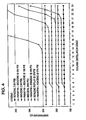
Fig. 2 is a graph showing the regeneration temperature profile throughout the column. -
Fig. 3 is a graph comparing experimental data on paraffin plus benzene regeneration with simulated paraffin plus benzene regeneration. -
Fig. 4 is a graph similar toFig. 3 showing simulated regenerations at higher pressures. -
Fig. 5 is a graph showing regeneration temperatures as a function of benzene reflux rates; and -
Fig. 6 is a graph showing the relationship between benzene reflux at various rates as a function of the mole % benzene. - By light aromatics or aromatic, we mean organic; aromatic compounds having one or more rings and from 6 to about 20 carbon atoms, that boil at or below about 250°C under pressure conditions typical in a commercial reactor-type distillation column. The preferred members of this group are benzene, toluene, xylene, styrene, phenol and cumene, with benzene being especially preferred.
- The preferred olefins include those straight chain mono-unsaturated olefins having from 2 to about 30 carbon atoms, preferably from about 8 to about 20 carbon atoms and, more preferably, from 10 to 14 carbon atoms. A particularly preferred olefin feedstock for detergent range alkylate comprises a mixture of C6-C18 olefins with C6-C18 paraffins derived from a conunercial paraffin dehydrogenation process.
- The preferred paraffins or paraffin feedstock suitable for use in the alkylation catalyst regeneration process of the present invention include paraffins having from C4 to C16 carbon atoms. In the case of gasoline range alkylation, paraffins of C4 to C16 carbon content, are preferred while in the case of detergent range alkylation, paraffins of C8 to C16 carbon content are preferred.
- The catalyst regeneration process of the present invention is conveniently carried out in a unified, continuous, reactive alkylation process such as that disclosed in
U.S. Patent 66424425 Fig. 1 , an olefin/paraffin mixture is injected below the benzene rectification zone at the top of the distillation column, but above the catalyst zone. The aromatic hydrocarbon is continuously injected at a point below the solid catalyst reactive zone and above a rectification zone, in which it can be separated from the alkylated product, paraffin and unreacted olefin that descends from the reactive zone on its way to the reboiler. - The alkylation reaction takes place primarily in the liquid phase on the solid catalyst in the reactive zone. Catalysts that may be employed for this invention include such acid zeolitic materials as W-Zeolite, beta-zeolite, acidic mordenite, acid days, such as montmorillonite and medium pore zeolites such as ZSM-5, ZSM-12, ZSM-18, ZSM-20, MCM-22, and BETA, L, Y, mordenite, as well as rare earth exchanged forms or de-aluminated forms of the listed zeolites. Other catalysts that may be employed in the practice of this invention are the fluorided versions of the above-mentioned zeolites and aluminum chloride impregnated on alumina, clays and silica-alumina. The catalyst can be maintained in place by supporting it on structured packing, such as Koch-Glitch KATAMAX brand catalytic structured packing, or alternatively arranged in other ways familiar to those skilled in this art, for example, in a series of beds on perforated trays or in beds positioned in the liquid down corners of a trayed distillation column. The structured can also be used in the rectification zones, without catalyst, to improve the evaporation and condensation efficiency in those zones.
- During the alkylation process, as disclosed in the referenced application, the molar ratio of the aromatic hydrocarbon to the liquid phase olefin in the reactive zone is maintained through adjustment of the column internal back pressure, the aromatic hydrocarbon reflux rate, the energy input into the reboiler, the amount of aromatic hydrocarbon removed while maintaining the column at or approaching total reflux, and the input flow of aromatic hydrocarbon. Coupling the reflux rate of the aromatic hydrocarbon with the relatively low introduction of additional aromatic hydrocarbon into the column will tend to increase the composition of aromatic hydrocarbon refluxing into the reactive zone and keep the molar ratio of the aromatic hydrocarbon to the olefin in the reactive catalyst zone at a higher level.
- The higher mole ratios of aromatic hydrocarbon to olefin that can be generated with counter-current flow of the liquid phase olefin and the higher reflux of aromatic compound into the reactive zone has been demonstrated to have several unexpected advantages:
- First, the higher aromatic compound to olefin mole ratios in the reactive zone enables a larger catalyst zone, tending to stabilize the reaction and make it very isothermal in the distillation column. Prior attempts to keep an isothermal process typically involved mixing the aromatic hydrocarbon with the feed of the olefin/paraffin mixture;
- Second, higher energy input to the reboiler to produce the higher reflux rates will be without the risk of exceeding the thermal degradation temperature that can occur in the reboiler at temperatures exceeding 265°C. High aromatic hydrocarbon reflex rates at constant energy input will tend to decrease the reboiler temperature as they force more aromatic hydrocarbon into the reboiler. Raising the internal pressure within the column can achieve higher catalyst reaction temperatures, thereby increasing yield, without the risk of exceeding a thermal degradation temperature in the reboiler.
- Third, the higher aromatic hydrocarbon to olefin molar ratios, as well as the isothermal nature of the reaction zone, can help increase the usable life of the catalyst. This is the result of the higher selectivity of the process of this invention for the mono-substituted alkylation, as opposed to poly-alkylation, which is known to poison most solid acid alkylation catalysts, requiring more frequent regeneration.
- In the example set forth below, the regeneration process of this invention was carried out in a continuous reactive distillation column depicted in
Fig. 1 . As shown inFig. 1 , for convenience, two separate columns were employed and designed to perform as a single reactive distillation column. Differential pressure control established vapor transport between the lower half (column 1) and the upper half (column 2). Liquid transport between upper segments (column 2) and lower segments (column 1) was handled by a pump and flow control from the base ofcolumn 2. - The catalysts employed were solid acid mordenite and Y zeolites. The catalyst is granulated to a 16 x 40 U.S. mesh size, dried at an appropriate temperature to activate it, and loaded into 54 KATAMAX catalyst packing elements. Each element has a 5 cm (2 inch) outside diameter and is 14 cm (5.5 inches) long. The mass of catalyst loaded into the column will depend on its density. However, since each of the KATAMAX elements all had the same internal catalyst volume (50.8cc), the catalyst was equally distributed by using 9 KATAMAX elements in each of Sections B, C, D, E, F, and G as shown in
Fig. 1 . Transition from detergent range alkylation tu catalyst regeneration is made by stopping the injection of the Q10 - C14 paraffin/olefin mixture and replacing it with a C8-C16 paraffin, while maintaining the benzene flow rate and reflux rate at the base of the column. In situ counter-current regeneration is achieved by raising the column pressure to between about 862 (125) to 1724 kPa (250 psig) while maintaining the benzene flow at a relatively low rate with high reflux. Once the column pressure and benzene reflux become stable again, the paraffin is injected from thestorage tank 1. The paraffin feed is pumped from astorage tank 1 at a controlled,rate using pump 2,Control Valve 3 andmass flow sensor 4. - The paraffin feed passes through a 4A
molecular sieve bed 5 where it is dried, and then throughpreheater 6, where the temperature is adjusted to match the measured reflux temperature inside the column at the point of injection. The temperature is monitored and adjusted upward to match the reflux temperature as the paraffin composition in the column increases. The point of paraffin injection is conveniently the same point as the olefin feed, that is, just above the KATAMAX catalyst elements in Section B, which is just below Section A, the rectification zone that separates and refluxes the aromatic hydrocarbon (which, in each of the examples, is benzene). Benzene injection temperatures at the base of the column and at the benzene reflux injection point are adjusted upward to match the increase in the reflux temperature as the paraffin content increases. The regeneration in this counter-current manner is maintained for about 8 to about 36 hours, depending on such parameters as the type of catalyst being used and the degree to which it became deactivated. - Following regeneration, transition back to the alkylation mode is achieved by stopping the flow of paraffin while maintaining or adjusting the flow of the aromatic hydrocarbon at the base of the catalyst bed to maintain the aromatic hydrocarbon in reflux. The column temperature is allowed to cool back to alkylation reaction temperature, while in aromatic hydrocarbon reflux condition. This is accomplished generally by gradually decreasing the column pressure back to the pressure at which the alkylation reaction takes place. The refluxing of the aromatic hydrocarbon acts to cool the column relatively quickly.
- At the appropriate temperature, olefin feedstock can be re-introduced to once again begin the alkylation process. In the example below, as in the referenced application, the preferred olefin feed set forth is a paraffin/olefin feedstock derived from a paraffin dehydrogenation process. The olcfin/paraffin mixture is pumped from
Feed Storage Tank 1 at a controlled rate, is passed through a 4Amolecular sieve bed 5 where it is dried, and then throughpreheater 6, where the temperature is adjusted to match the measured reflux temperature inside the column at the point of injection. The injection temperature is monitored and adjusted upward to match the measured reflux temperature inside the distillation column at the point of injection. The point of olefin feed injection is just above the KATAMAX catalyst elements in Section B, which is just below Section A, the rectification zone that separates and refluxes the aromatic hydrocarbon (which, in each of the examples, is benzene). - The aromatic hydrocarbon is pumped from
storage tank 11 usingpump 12, with flow controlled bycontrol valve 13 and monitored usingmass flow meter 14. Prior to injection, the aromatic hydrocarbon is also passed through amolecular sieve dryer 15 andpreheater 16 and is heated to about 5-10°C. below its boiling point at the experimental internal column pressure. Thus, it is injected as a liquid, but generally will quickly flash due to the heat from the liquid and vapor rising out of the reboiler. As depicted inFig. 1 , theinjection point 17 of the aromatic hydrocarbon is at the base of Section G, but above the rectification zone (Section H) which is immediately above thereboiler 40. This is the primary injection point and sets up the counter-current flow of aromatic hydrocarbon with the olefin descending as a liquid from its injection point 7 (above the catalyst in Section B). - The aromatic hydrocarbon employed in the example was benzene. Benzene vapor in the column is taken overhead and condensed in cooler 19 and accumulated in
vessel 20. The accumulated benzene is reinjected as reflux atpoint 21 in rectification zone A. As will be appreciated by those skilled in the art, this can be through level control from theaccumulator vessel 20 or on flow control to the column along with a stream that removes excess benzene storage totank 25 using the appropriate monitoring and flow controlling apparatus. - The desired operating pressure is adjusted and maintained using cascade control with appropriate nitrogen injection and venting into and out of the
accumulator tank 20. The two column configuration depicted in the drawing was also used in the example. The two columns were operated as one by means of heaters and flow control valves. The benzene vapor, as it leaves Section E and flows between the columns, is maintained at the appropriate temperature and pressure by means of an electrically heated and controlledvapor transport line 26. Benzene vapor enters the base of Section D of the column atpoint 27 and continues through segments D, C and B. The flow between the columns is controlled atcontrol valve 23 using a relatively low differential pressure, usually about 14 kPa (2 psig). - Unreacted olefin and paraffin, as well as crude alkylate product, any by-product and liquid phase benzene are accumulated in
vessel 30, below Section D, cooled at 35, and pumped to the top of Section E on level control. The liquid frompump 32 is reheated at 34 to precisely the reflux temperature of the column at theinjection point 35. The liquid then continues to descend through the catalyst zone (Sections E, F and G into rectification zone H andreboiler 40. Crude linear alkyl benzene product, paraffin, higher molecular weight bottoms product and trace levels of unreacted olefin, if present, removed throughreboiler 40 on level control and pumped to storage intank 45. - there are two liquid phase sample points at which the data on the crude alkylate product, as set forth in
tablets benzene overhead accumulator 20. This can be used to measure benzene purity. - A unique feature of the reactive distillation unit of the present invention is the ability to regenerate the catalyst in situ at a set of regeneration conditions that are in general milder then those required to regenerate a plug flow fixed bed catalytic reactor. Typically' the fixed bed process calls for the use of pure benzene to be maintained in the liquid phase at 3447 kPa (500 psig) and 250°C regeneration temperature.
- An example of catalyst deactivation and subsequent regeneration for the reactive distillation process was conducted as follows. A 1379.27 g of TOSOH 330Y was loaded into the 54 KATAMAX structured packing elements and placed in the reactive distillation column shown in
Fig. 1 . The reboiler was charged with benzene and the column was brought to reflux benzene at 345 (50) - 359 kPa (52 psig) column pressure. Paraffin/olefin feed shown inFig. 1 as feed to section B was initiated at 50 g/min. Benzene injection at the base of the column, section G, was maintained at 10 g/min. The reactive distillation column was operated at the conditions listed in Table 2. Samples of liquid product were removed from two sample points. Sample point A is cooled liquid product removed from the reboiler and represents the total conversion in the reactive distillation column. Sample point B is a cooled liquid sample removed from the intermediate accumulator at the base of column, section D. This sample point represents the conversion at 50% of the catalyst volume. The TOSOH 330 Y zeolite solid acid catalyst was operated per the condition shown in Table 2 for a total of 118.5 hours on stream. During this operating period the TOSOH 330 Y experienced significant deactivation. The conversion at point B was initially 99.96 % with a residual bromine index in the crude benzene, paraffin/olefin and alkylate product of 1.1 cg/g. The catalyst in sections B, C, and D experienced significant deactivation as the conversion dropped to 24.7% (Bromine Index 2185) at 118.5 hours on stream. Similarly Sections E, F, and G experienced deactivation from 100% conversion (Bromine index non detectable) to 88.8% conversion with a residual bromine index of 829 cg/g. The catalyst deactivates from top to bottom in the distillation column. After 118.5 hours on stream, the paraffin/olefin mixture was discontinued and the column refluxed benzene at 134°C for 2 hours as the crude alkylate is washed from the catalyst bed into the reboiler. During this period the paraffin/olefin feed in the storage tank was replaced with a paraffin feed of the same molecular weight and carbon number distribution as shown in Table 1. The column back pressure is increased to 862 kPa (125 psig) and the benzene reflux stabilizes at 862 kPa (125 psig). A uniform column temperature of only 172°-175°C is achieved with benzene reflux at 862 kPa (125 psig) back pressure. Paraffin injection is initiated at 50 g/min through H101 at a point just above the first section containing the catalyst structured packing. The counter-current paraffin injection alters the composition in the column which increases the reflux temperature. The counter-current paraffin flow establishes a regeneration temperature profile as shown inFig. 2 . This increases the column temperature profile from the uniform 172-175°C with benzene reflux to the range of 187° to 205°C. Additional heating was applied to the column through skin heaters in order to reach the 200°C regeneration temperature at 862 kPa (125 psig). The additional heating is required to achieve the regeneration temperature due to the mechanical upper pressure limit on the reactive distillation column. The regeneration conditions used in this example are paraffin rate: 50 g/min, benzene rate 10 g/min, column back pressure 862 kPa (125 psig), and benzene set on total reflux at the top of the column. This counter-current paraffin regeneration was maintained for 24 hours. The number of hours can vary from 8 to 36 hours depending on the degree of deactivation of the catalyst. Following regeneration, the paraffin flow is stopped, the column is cooled and pressure readjusted to 345 kPa (50 psig) reaction pressure in a benzene reflux. Once the column is stable at 345 kPa (50 psig) and under benzene reflux, the paraffin/olefin feed is re-established at the top of section G. The analysis of liquid samples from sample points A and B confirms that the catalyst has been completely regenerated.Table 1 Capillary GC Analysis of Paraffin/Olefin Feed Feed A B Weight % Weight % < C 100 0 C10 1.53 1.98 C11 3.85 3.71 C12 3.83 3.83 C13 2.45 2.44 C14 0.33 0.36 C 150 0 Total Olefin 11.99 12.32 Linear Paraffin < C10 0.18 0.07 C10 14.42 19.09 C11 31.84 29.72 C12 26.43 24.88 C13 14.42 13.25 C14 0.62 0.48 C15 0.19 0.2 Total Paraffin 88.1 87.69 Avg MW (g/mole) 163.6 162.9 Bromine No.(Cg/g)) 10.8 10.4 Table 2 Time on Stream (hrs.) Sample Point B Olefin % Com Sample Point B Bromine Index (cg/g) Sample Point A Olefin % Conv Sample Point A Bromine Index (cg/g) Paraffin * Olefin injection Rate (g/min) Benzene Feed Injection Rate (g/min) Column Pressure (psig) Average Catalyst Zone Temp. (°C) Reflux Benzene Injection Rate (g/min) Liquid Phase Benzene/Olefin Mole Ratio 5 100 0 99.96 1.1 50.5 10.1 52 144 194 57 7 99.94 4.2 85.3 375 49.9 9.8 52 144 192 54 25 99.9 5 83.6 410 49.9 10.1 52 140 127 91 28 100 3 83.6 426 49.9 10.0 52 144 211 73 31 100 1 83.9 450 48.7 9.8 52 144 176 54 52 100 1 28.9 2347 49.7 10.0 51 144 163 46 54 100 1 28.3 2151 49.5 10.0 51 141 146 53 84.5 95.6 309 18.9 2351 49.8 9.5 51 143 167 55 88.5 95.8 293 20.6 2222 49.5 9.8 51 144 172 59 89.5 96.5 216 12.0 2199 50.1 10.1 52 144 171 58 116.5 64.5 1058 20 2080 50.1 10 52 144 177 62 118.5 88.8 829 24.7 2185 60.1 9.8 52 144 177 65 Regeneration for 24 hours at 187-205°C using Counter current Paraffin and Benzene 6 100 1 100 1 49.7 10 50 141 85 30 8 100 1 100 1 49.7 9.9 50 141 68 27 10 100 1 98.3 27 49.6 9.8 50 141 61 25 - The injection of paraffin above the catalyst is one means of increasing the steady state regeneration temperature in the reactive distillation column. This paraffin injection provides a temperature increase as well as additional washing action to transport the by-products on the catalyst and transfers them to the reboiler. This effect of increased regeneration temperature with paraffin injection can be applied at higher pressure and will continue to achieve a stepwise advantage for reaching higher regeneration temperature at a given distillation column pressure. This effect can be modeled to determine the extent of the advantage beyond the pressure limit of the experimental reactive distillation column shown in
Fig. 1 . Table 3 andFig. 3 compare experimental data at 862 kPa (125 psig), 50 g/min of C10-C13 paraffin injection above the catalyst bed, and 10 g/min. benzene injected below the bed at the base of section G with distillation, simulation using ASPEN Plus 10.1. The simulation conditions arc identical to the experimental operating conditions with n-dodccane used to simulate the injected paraffin. The catalyst bed lies betweenStage Fig. 1 .Fig. 3 shows a good correlation between experimental data and the simulation. The advantage of counter-current paraffin injection and benzene at reflux can he shown by further simulations at higher column back pressures. These higher pressure simulations using ASPEN Plus 10.1, were all conducted at 50 g/min n-dodccane injection, 10 g/min benzene injection into Section G and at total benzene reflux. The data for the higher pressure simulations are shown in Table 4 and graphed inFig. 4 . The simulation at 1241 kPa (180 psig) shows that a regeneration temperature of 200°C will be achieved. Increasing the pressure to 1793 kPa (260 psig) can achieve a regeneration temperature of 224°C. Increasing the column back pressure to 370°C will achieve a regeneration temperature of 250°C. The simulations indicate that the combination of a counter-current paraffin injection with total benzene reflux will achieve increases in regeneration temperature of 8 to 12 degrees Centigrade while - maintaining a uniform temperature in the catalyst zone placed between
stages Table 3 Reactive Distillation Column Temperature Points Simulation Stage Number Benzene Simulation Paraffin + Benzene Regeneration Simulation Experimental Benzene Reflux Profile Exp Paraffin + Benzene Regeneration Profile Overhead Vapor Temp 1 170.379 170.379 171.379 167.8276 2 170.379 170.379 3 170.379 170.380 4 170.379 170.387 DA-220-1 5 170.380 170.634 173.439 173.3027 6 170.388 178.316 DA-220-2 7 170.388 178.317 173.355 179.8502 8 170.388 178.317 DA-220-3 9 170.388 178.317 173.138 180.136 10 170.388 178.317 DA-220-4 11 170.388 178.317 170.337 178.9793 12 170.388 178.317 TI-215 13 170.388 178.317 174.791 181.7515 14 170.388 178.317 DA-210-1 15 170.388 178.317 174.700 187.0356 16 170.388 178.318 DA-210-2 17 170.388 178.318 174.719 191.2626 18 170.388 178.318 DA-210-3 19 170.388 178.320 176.403 195.5427 20 170.388 178.382 21 170.388 179.122 22 170.388 187.080 DA-210-4 23 170.393 230.409 176.306 224.8719 Reboiler Temp 24 170.561 291.900 175.140 265.1487 Table 4 ASPEN Plus 10.1 Simulation of Effect of Paraffin Injection at the Top of the Catalyst Bed (above Stage 6) as a function of Column Back Pressure Column Distillation Stage Benzene Reflux @ 125 psi Paraffin + Benzene @ 125 psi Temperature Increase in Catalyst (C) Benzene Reflux @ 180 psi Paraffin + Benzene @ 180 psi Temperature Increase in Catalyst (C) Benzene Reflux @ 280 psi Paraffin + Benzene @ 280 psi Temperature Increase In Catalyst (C) Benzene Reflux @ 370 psi Paraffin + Benzene @ 370 psi Temperature Increase in Catalyst (C) Top 1 170.38 170.38 0.00 191.01 191.1y9 0.18 214.27 211.28 0.00 238.57 238.57 0.00 2 170.38 170.38 0.00 191.01 191.19 0.18 214.27 214.28 0.00 238.51 276.57 0.00 3 170.38 170.38 0.00 191.01 191.19 0.18 214.27 214.28 0.00 236.51 239.57 0.00 4 170.38 170.39 0.01 191.01 191.20 0.19 214.27 214.30 0.02 238.57 238.61 0.04 5 170.38 170.63 0.25 191.01 191.54 0.52 214.27 214.79 0.51 238.57 239.34 0.77 6 170.38 178.32 7.93 191.01 199.90 8.89 214.27 224.34 10.07 238.57 250.32 11.76 7 170.38 179.32 7.93 101.01 199.90 8.80 214.28 224.34 10.07 238.51 250.32 11.76 8 170.36 178.32 7.93 191.01 198.90 8.89 214.28 224.34 10.07 238.57 250.32 11.78 9 170.38 178.32 7.93 191.01 199.90 8.89 214.28 224.34 10.07 238.57 250.32 11.78 10 170.36 178.32 7.93 191.01 199.90 8.89 214.28 224.34 10.07 238.57 250.33 11.78 11 170.38 178.32 7.93 191.01 199.90 8.89 214.28 224.34 10.07 236.57 250.34 11.77 12 170.38 170.32 7.93 191.01 199.90 8.69 214.28 224.34 10.07 238.57 250.42 11.65 13 170.38 178.32 7.93 101.01 199.90 8.89 214.28 224.34 10.07 236.57 250.85 12.28 14 170.38 178.32 7.93 101.01 199.00 8.69 214.28 224.34 10.07 238.57 253.09 14.52 15 170.38 178.32 7.93 101.01 199.90 8.89 214.28 224.34 10.07 238.57 263.78 25.21 16 170.36 178.32 7.93 19.01 180.90 8.89 214.28 224.35 10.07 238.57 30.99 66.42 17 170.38 178.32 7.93 191.01 199.90 8.89 214.28 224.39 10.12 238.57 364.42 125.66 18 170.38 178.32 7.93 191.01 199.91 8.89 214.28 224.70 10.43 236.57 410.14 171.57 19 170.38 176.92 7.94 191.01 199.92 8.91 214.28 226.83 12.56 238.57 446.67 208.11 20 170.38 170.38 8.00 191.01 200.05 9.04 214.28 239.46 25.19 238.57 466.16 227.59 21 170.38 179.12 6.74 191.01 204.99 13.97 214.28 288.01 73.73 238.58 417.54 238.97 22 170.38 187.06 16.70 191.01 235.15 44.14 214.28 350.28 136.01 238.56 482.38 243.82 23 170.38 23.41 60.03 191.01 299.93 108.91 214.28 373.54 159.26 238.56 484.47 245.91 Reboiler 24 110.38 291.90 121.52 191.01 335.39 144.37 214.28 383.44 169.17 238.58 485.40 216.82 - The data in Table 4 show that at high benzene reflux rates which achieve greater than 80 mole % benzene composition in the column, the paraffin injection provides an unexpected 7 to 15°C temperature increase at all pressures from 861 kPa (125 psig) to 2551 kPa (370 psig). This confirms the experimental results of Example 2 as seen in Table 3.
- Another mode of column operation can also be used to achieve high regeneration temperatures without significant increases in column pressure. This mode of operation also uses counter-current paraffin injection at the top of the catalyst bed and injection of benzene below the catalyst but maintained at reflux. A significant unexpected advantage from reducing the benzene reflux rate with paraffin injection was observed through ASPEN Simulation. Target regeneration temperatures in the range of 200° to 250°C could be achieved by reducing the benzene reflux from 150 g/min down to 18 g/min while maintaining liquid phase benzene molar compositions of 50% to 87% in the catalyst zone. ASPEN Plus 10.1 using a RAD FRAC Model was used to determine the composition in the distillation column and the temperature in the catalyst zone. Simulation data is summarized in Table 5 and plotted in
Fig. 5 andFig. 6 . The data shows that a steady state regeneration temperature of 200°C within the catalyst bed (Stage 6 to Stage 18) can be achieved while maintaining a benzene liquid phase mole fraction of 67 mole %. This column composition and temperature is achieved at a reflux rate of 54 g/min of benzene at the top of the column. Similarly, a regeneration temperature of 223°C is achieved with a further reduction of benzene reflux to 18 g/min while still maintaining a liquid phase molar benzene composition of 49 mole % in the catalyst zone. These compositions can be maintained for the 8 to 36 hours required to regenerate the catalyst.Table 5 ASPEN Plus 10.1 RAD FRAC Simulation of Counter Current n-dodecane and Benzene Reflux at 125 psig, 50 g/min C12,10 g/min Benzene Benzene Reflux Rate 150 g/min Benzene Reflux Rate 54 g/min Benzene Reflux Rate 18 g/min Simulation Stage Number Internal Temperature (C) Benzene Liquid Mole Fraction Internal Temperature (C) Benzene Liquid Mole Fraction Internal Temperature (C) Benzene Liquid Mole Fraction 1 176.51 1.00000 176.04 0.99998 176.04 0.99994 2 176.51 1.00000 176.05 0.99974 176.08 0.99932 3 176.52 1.00000 176.23 0.99686 176.54 0.99193 4 176.53 0.99985 178.38 0.96204 182.08 0.90344 5 176.87 0.99461 200.69 0.61613 223.78 0.49139 6 186.55 0.87617 200.69 0.61613 223.78 0.49139 7 186.55 0.87618 200.69 0.67613 223.78 0.49139 8 186.55 0.87618 200.69 0.61613 223.78 0.49140 9 186.55 0.87617 200.69 0.67613 223.78 0.49141 10 186.55 0.87617 200.69 0.67615 223.77 0.49147 11 186.55 0.87617 200.68 0.67623 223.74 0.49164 12 186.55 0.87618 200.65 0.67657 223.66 0.49220 13 186.55 0.87618 200.62 0.67685 223.59 0.49264 14 186.55 0.87618 200.62 0.67686 223.58 0.49269 15 186.55 0.87618 200.62 0.61687 223.56 0.49286 16 186.55 0.87618 200.61 0.67694 223.48 0.49338 17 186.55 0.87618 200.58 0.61124 223.22 0.49510 18 186.55 0.87617 200.43 0.67865 222.36 0.50088 19 186.55 0.87616 199.78 0.68514 219.41 0.52122 20 186.72 0.87450 199.87 0.68420 219.46 0.52084 21 188.28 0.85885 200.40 0.67896 219.76 0.51876 22 201.14 0.75098 203.30 0.65123 221.34 0.50780 23 250.36 0.49332 217.20 0.53703 229.26 0.45651 24 306.20 0.30367 258.66 0.30356 258.66 0.30356 - As seen in Table 5, at operating pressures as low as 862 kPa (125 psig) and with sufficient paraffin injection, one can achieve a significant increase in column regeneration temperature by reducing the benzene reflux rate but still maintain significant and needed benzene concentration in the column. Thus, as seen from the data in Table 5, a reduction of the benzene concentration from 87 mole % to 50 mole % will shift the column regeneration temperature from about 186°C to about 250°C.
- As noted above, the counter-current paraffin injection permits a selection and tailoring of the regeneration conditions to suit a given catalyst. Some catalysts may require higher benzene concentrations at a given regeneration temperature. Those conditions can be achieved with paraffin injection and by adjusting the benzene reflux rate. Thus, one can achieve regeneration temperature at lower pressure and still maintain proper benzene composition.
Claims (6)
- A process for the regeneration of a solid acid alkylation catalyst in a reactive distillation alkylation process taking place in a pressurized distillation column including an intermediate reactive catalyst zone having supported therein a solid acid alkylation catalyst, a first rectification zone at the top of the distillation column and a second rectification zone including a reboiler below said reactive catalyst zone, wherein at least a portion of an olefin-containing feedstock, introduced between the intermediate catalyst zone and the upper rectification zone, is brought into contact with at least a portion of an aromatic hydrocarbon feedstock, introduced between the catalyst zone and the second, lower rectification zone in countercurrent flow within the reactive catalyst zone, wherein the internal pressure in the reactive catalyst zone is maintained above 101 kPa (1 atmosphere) and the temperature maintained at reflux of said aromatic hydrocarbon feedstock comprising:A. periodically ceasing the introduction into the distillation column of the olefin-containing feedstock while continuing the flow of aromatic hydrocarbon feedstock and introducing into the column an effective amount of a paraffin feedstock at a point such that the paraffin feedstock intermixes in counter-current flow with the refluxing unreacted aromatic hydrocarbon feedstock as it flows through the catalyst to remove by-products from the catalyst;B. adjusting the reflux rate of said aromatic hydrocarbon to achieve a desired temperature in the catalyst reaction zone above about 175°C at a column operating pressure within the range of from 862 (125 psig) to 2551 kPa (370 psig);C. separating said by-products from said paraffin and aromatic hydrocarbon in said second rectification zone; andD. removing said by-products from said rectification zone.
- The process of Claim 1 where said second rectification zone includes a reboiler and said by-products are removed from said reboiler.
- The process of Claim 1 wherein the paraffin feedstock is such that the mole percent of aromatic hydrocarbon in the catalyst zone is maintained at between about 40% to about 90%.
- The process of Claim 1 wherein the regeneration is carried out for a period of from about 8 to about 36 hours.
- The process of Claim 1 wherein said paraffin feedstock comprises C4 to C16 paraffins.
- The process of Claim 5 wherein said paraffin feedstock comprises C8 to C16 paraffins.
Applications Claiming Priority (3)
| Application Number | Priority Date | Filing Date | Title |
|---|---|---|---|
| US10/090,859 US7199068B2 (en) | 2002-03-05 | 2002-03-05 | Reactive distillation alkylation process including in situ catalyst regeneration |
| US90859 | 2002-03-05 | ||
| PCT/US2003/001432 WO2003076074A1 (en) | 2002-03-05 | 2003-01-16 | A reactive distillation alkylation process including in situ catalyst regeneration |
Publications (3)
| Publication Number | Publication Date |
|---|---|
| EP1480746A1 EP1480746A1 (en) | 2004-12-01 |
| EP1480746A4 EP1480746A4 (en) | 2005-07-27 |
| EP1480746B1 true EP1480746B1 (en) | 2010-10-20 |
Family
ID=27804071
Family Applications (1)
| Application Number | Title | Priority Date | Filing Date |
|---|---|---|---|
| EP03703858A Expired - Lifetime EP1480746B1 (en) | 2002-03-05 | 2003-01-16 | A reactive distillation alkylation process including in situ catalyst regeneration |
Country Status (20)
| Country | Link |
|---|---|
| US (1) | US7199068B2 (en) |
| EP (1) | EP1480746B1 (en) |
| JP (1) | JP4526267B2 (en) |
| KR (1) | KR100944565B1 (en) |
| CN (1) | CN100418631C (en) |
| AT (1) | ATE485253T1 (en) |
| AU (1) | AU2003205189B2 (en) |
| BR (1) | BR0308241A (en) |
| CA (1) | CA2477127A1 (en) |
| CO (1) | CO5631414A2 (en) |
| DE (1) | DE60334606D1 (en) |
| EA (1) | EA006786B1 (en) |
| EC (1) | ECSP045272A (en) |
| EG (1) | EG23500A (en) |
| HN (1) | HN2004000357A (en) |
| IL (2) | IL163618A0 (en) |
| MX (1) | MXPA04008562A (en) |
| NO (1) | NO327663B1 (en) |
| WO (1) | WO2003076074A1 (en) |
| ZA (1) | ZA200406622B (en) |
Families Citing this family (25)
| Publication number | Priority date | Publication date | Assignee | Title |
|---|---|---|---|---|
| US7449420B2 (en) * | 2003-03-21 | 2008-11-11 | Stone & Webster Inc. | Production of alkyl aromatic compounds with catalyst reactivation |
| US7498474B2 (en) | 2005-02-28 | 2009-03-03 | Exxonmobil Research And Engineering Company | Vapor phase aromatics alkylation process |
| US7476774B2 (en) | 2005-02-28 | 2009-01-13 | Exxonmobil Research And Engineering Company | Liquid phase aromatics alkylation process |
| US7525002B2 (en) | 2005-02-28 | 2009-04-28 | Exxonmobil Research And Engineering Company | Gasoline production by olefin polymerization with aromatics alkylation |
| US20080029435A1 (en) * | 2006-08-02 | 2008-02-07 | Exxonmobil Research And Engineering Company | Rejuvenation process for olefin polymerization and alkylation catalyst |
| US7981256B2 (en) * | 2007-11-09 | 2011-07-19 | Uop Llc | Splitter with multi-stage heat pump compressor and inter-reboiler |
| US8586496B2 (en) * | 2008-07-22 | 2013-11-19 | Exxonmobil Chemical Patents Inc. | Preparation of molecular sieve catalysts and their use in the production of alkylaromatic hydrocarbons |
| US8395006B2 (en) | 2009-03-13 | 2013-03-12 | Exxonmobil Research And Engineering Company | Process for making high octane gasoline with reduced benzene content by benzene alkylation at high benzene conversion |
| JP5551234B2 (en) | 2009-03-16 | 2014-07-16 | サウディ ベーシック インダストリーズ コーポレイション | Nickel / lanthanum oxide catalyst for producing synthesis gas |
| US8935847B2 (en) * | 2009-09-17 | 2015-01-20 | Lester F. Ludwig | Modular reactive distillation emulation elements integrated with instrumentation, control, and simulation algorithms |
| EA024093B1 (en) | 2010-12-22 | 2016-08-31 | Сауди Бейсик Индастриз Корпорейшн | Catalyst useful in fisher-tropsch synthesis |
| CN103648639B (en) | 2011-04-19 | 2016-10-12 | 沙特基础工业公司 | Carbon-Supported Cobalt and Molybdenum Catalysts |
| WO2013007345A1 (en) | 2011-07-08 | 2013-01-17 | Saudi Basic Industries Corporation | Improved carbon supported cobalt and molybdenum catalyst and use thereof for producing lower alcohols |
| EP2679568A1 (en) | 2012-06-25 | 2014-01-01 | Saudi Basic Industries Corporation | Process for production ethylene and propylene from syngas |
| EA029026B1 (en) | 2012-06-27 | 2018-01-31 | Сауди Бейсик Индастриз Корпорейшн | Catalyst and process for the selective production of lower hydrocarbons c1-c5 from syngass with low methane and coproduction |
| US9827555B2 (en) | 2013-07-31 | 2017-11-28 | Saudi Basic Industries Corporation | Catalyst for conversion of synthesis gas |
| BR102014002154A2 (en) * | 2014-01-28 | 2015-10-27 | Whirlpool Sa | alkylaryl compound production process, polyalkyl aromatic transalkylation process for selective production of monoalkyl aromatic compound, and alkylation and transalkylation process of aromatic and / or polyaromatic compounds |
| US9732014B2 (en) | 2014-03-07 | 2017-08-15 | Uop Llc | Method of producing alkylaromatic compounds using aromatic compound from catalyst regeneration |
| US9751817B2 (en) | 2014-03-07 | 2017-09-05 | Uop Llc | Combined reactor effluent and regenerant recirculation for detergent alkylation process |
| JP6228246B2 (en) | 2015-03-03 | 2017-11-08 | エボニック デグサ ゲーエムベーハーEvonik Degussa GmbH | Regeneration of heterogeneous catalysts used for ethene oligomerization |
| CN111203287A (en) * | 2018-11-21 | 2020-05-29 | 内蒙古伊泰煤基新材料研究院有限公司 | Regeneration method of benzene alkylation solid acid catalyst |
| CN112642476B (en) * | 2019-10-09 | 2023-04-07 | 中国石油化工股份有限公司 | Activity control method for in-situ coke removal of aromatic hydrocarbon olefin removal catalyst and application thereof |
| CN111763130B (en) | 2020-06-22 | 2023-01-03 | 南京克米斯璀新能源科技有限公司 | Method for producing long-chain alkylbenzene |
| CN116262881B (en) * | 2021-12-14 | 2025-12-30 | 中国石油化工股份有限公司 | A method for selectively removing olefin impurities from reforming oil |
| CN120132389B (en) * | 2025-04-03 | 2025-12-23 | 广东百宏裕能新材料科技有限公司 | Rectification purification method for recovering NMP from NMP regenerated liquid |
Family Cites Families (13)
| Publication number | Priority date | Publication date | Assignee | Title |
|---|---|---|---|---|
| ES2007545A6 (en) * | 1988-08-03 | 1989-06-16 | Petroquimica Espanola S A Petr | Alkylation of aromatic hydrocarbons in a fixed bed catalytic process. |
| US5082990A (en) | 1988-10-28 | 1992-01-21 | Chevron Research And Technology Company | Alkylation of aromatics-containing refinery streams |
| US5019669A (en) | 1989-03-10 | 1991-05-28 | Chemical Research & Licensing Company | Alkylation of organic aromatic compounds |
| US5326923A (en) * | 1990-09-26 | 1994-07-05 | Catalytica, Inc. | Method for regenerating certain acidic hydrocarbon conversion catalysts by solvent extraction |
| US5258560A (en) | 1992-06-22 | 1993-11-02 | Uop | Etherification of C5 -plus olefins by catalytic distillation |
| US5648579A (en) * | 1993-09-27 | 1997-07-15 | Uop | Continuous alkylation of aromatics using solid catalysts; prevention of catalyst deactivation using a pulsed feed reactor |
| FR2721603B1 (en) * | 1994-06-22 | 1996-09-20 | Inst Francais Du Petrole | Rejuvenation process for a solid alkylation catalyst. |
| US5672798A (en) * | 1994-10-14 | 1997-09-30 | Uop | Fluidized bed solid catalyst motor fuel alkylation process |
| FR2732012B1 (en) * | 1995-03-24 | 1997-05-23 | Inst Francais Du Petrole | PROCESS FOR THE ALKYLATION OF PARAFFINS |
| US5770782A (en) | 1996-02-08 | 1998-06-23 | Huntsman Petrochemical Corporation | Process and system for alkylation of aromatic compounds |
| IT1313009B1 (en) * | 1999-07-13 | 2002-05-29 | Enichem Spa | PROCESS FOR THE REGENERATION OF ZEOLITHIC CATALYSTS. |
| AU2000244974A1 (en) | 2000-04-28 | 2001-11-12 | Mobil Oil Corporation | Regeneration of aromatic alkylation catalysts using hydrocarbon stripping |
| US6642425B2 (en) | 2002-03-05 | 2003-11-04 | Sasol North America Inc. | Reactive distillation process for the alkylation of aromatic hydrocarbons |
-
2002
- 2002-03-05 US US10/090,859 patent/US7199068B2/en not_active Expired - Fee Related
-
2003
- 2003-01-16 EA EA200401155A patent/EA006786B1/en not_active IP Right Cessation
- 2003-01-16 AU AU2003205189A patent/AU2003205189B2/en not_active Ceased
- 2003-01-16 WO PCT/US2003/001432 patent/WO2003076074A1/en not_active Ceased
- 2003-01-16 MX MXPA04008562A patent/MXPA04008562A/en active IP Right Grant
- 2003-01-16 CN CNB038052563A patent/CN100418631C/en not_active Expired - Fee Related
- 2003-01-16 BR BR0308241-5A patent/BR0308241A/en not_active IP Right Cessation
- 2003-01-16 DE DE60334606T patent/DE60334606D1/en not_active Expired - Lifetime
- 2003-01-16 EP EP03703858A patent/EP1480746B1/en not_active Expired - Lifetime
- 2003-01-16 CA CA002477127A patent/CA2477127A1/en not_active Abandoned
- 2003-01-16 JP JP2003574333A patent/JP4526267B2/en not_active Expired - Fee Related
- 2003-01-16 AT AT03703858T patent/ATE485253T1/en not_active IP Right Cessation
- 2003-01-16 KR KR1020047013811A patent/KR100944565B1/en not_active Expired - Fee Related
- 2003-01-16 IL IL16361803A patent/IL163618A0/en active IP Right Grant
-
2004
- 2004-08-19 IL IL163618A patent/IL163618A/en not_active IP Right Cessation
- 2004-08-19 ZA ZA200406622A patent/ZA200406622B/en unknown
- 2004-09-02 EC EC2004005272A patent/ECSP045272A/en unknown
- 2004-09-03 CO CO04086986A patent/CO5631414A2/en not_active Application Discontinuation
- 2004-09-04 EG EGNA2004000085 patent/EG23500A/en active
- 2004-09-10 HN HN2004000357A patent/HN2004000357A/en unknown
- 2004-09-27 NO NO20044083A patent/NO327663B1/en not_active IP Right Cessation
Also Published As
| Publication number | Publication date |
|---|---|
| IL163618A0 (en) | 2005-12-18 |
| WO2003076074A1 (en) | 2003-09-18 |
| DE60334606D1 (en) | 2010-12-02 |
| KR100944565B1 (en) | 2010-02-25 |
| EP1480746A4 (en) | 2005-07-27 |
| MXPA04008562A (en) | 2005-05-05 |
| CN1638870A (en) | 2005-07-13 |
| JP4526267B2 (en) | 2010-08-18 |
| NO20044083L (en) | 2004-10-01 |
| CO5631414A2 (en) | 2006-04-28 |
| US7199068B2 (en) | 2007-04-03 |
| EA006786B1 (en) | 2006-04-28 |
| NO327663B1 (en) | 2009-09-07 |
| AU2003205189B2 (en) | 2008-04-10 |
| AU2003205189A1 (en) | 2003-09-22 |
| CA2477127A1 (en) | 2003-09-18 |
| EA200401155A1 (en) | 2005-02-24 |
| IL163618A (en) | 2008-04-13 |
| JP2005518939A (en) | 2005-06-30 |
| CN100418631C (en) | 2008-09-17 |
| ZA200406622B (en) | 2006-06-28 |
| BR0308241A (en) | 2005-05-24 |
| HN2004000357A (en) | 2008-10-07 |
| KR20040095261A (en) | 2004-11-12 |
| ECSP045272A (en) | 2005-01-28 |
| EG23500A (en) | 2006-01-17 |
| US20030171204A1 (en) | 2003-09-11 |
| EP1480746A1 (en) | 2004-12-01 |
| ATE485253T1 (en) | 2010-11-15 |
Similar Documents
| Publication | Publication Date | Title |
|---|---|---|
| US7199068B2 (en) | Reactive distillation alkylation process including in situ catalyst regeneration | |
| US6642425B2 (en) | Reactive distillation process for the alkylation of aromatic hydrocarbons | |
| AU609516B2 (en) | Alkylation/transalkylation process for selective production of monoalkylated aromatics | |
| US4857666A (en) | Alkylation/transalkylation process | |
| EP1140739B1 (en) | Improved aromatic alkylation process | |
| TWI335239B (en) | Production of alkyl aromatic compounds with catalyst reactivation | |
| KR101837521B1 (en) | Process for producing cumene | |
| JPH10511942A (en) | Continuous method for producing ethylbenzene using liquid-phase alkylation and gas-phase transalkylation reactions | |
| KR20000016605A (en) | Two-step process for alkylation of benzene to form linear alkylbenzenes | |
| CA2309440A1 (en) | Alkylaromatics production | |
| EP2109595B1 (en) | Energy integrated processes for making detergent range alkylbenzenes | |
| US20080194893A1 (en) | Energy Integrated Processes including alkylation and transalkylation For Making Detergent Range Alkylbenzenes | |
| US20080194898A1 (en) | Transalkytion of dialkylbenzene | |
| JPH08501082A (en) | A new method for aromatic alkylation. |
Legal Events
| Date | Code | Title | Description |
|---|---|---|---|
| PUAI | Public reference made under article 153(3) epc to a published international application that has entered the european phase |
Free format text: ORIGINAL CODE: 0009012 |
|
| 17P | Request for examination filed |
Effective date: 20040902 |
|
| AK | Designated contracting states |
Kind code of ref document: A1 Designated state(s): AT BE BG CH CY CZ DE DK EE ES FI FR GB GR HU IE IT LI LU MC NL PT SE SI SK TR |
|
| AX | Request for extension of the european patent |
Extension state: AL LT LV MK RO |
|
| A4 | Supplementary search report drawn up and despatched |
Effective date: 20050609 |
|
| RIC1 | Information provided on ipc code assigned before grant |
Ipc: 7B 01D 3/00 B Ipc: 7B 01J 29/90 B Ipc: 7B 01J 38/56 B Ipc: 7C 07C 2/66 A |
|
| 17Q | First examination report despatched |
Effective date: 20081110 |
|
| GRAP | Despatch of communication of intention to grant a patent |
Free format text: ORIGINAL CODE: EPIDOSNIGR1 |
|
| GRAS | Grant fee paid |
Free format text: ORIGINAL CODE: EPIDOSNIGR3 |
|
| GRAA | (expected) grant |
Free format text: ORIGINAL CODE: 0009210 |
|
| AK | Designated contracting states |
Kind code of ref document: B1 Designated state(s): AT BE BG CH CY CZ DE DK EE ES FI FR GB GR HU IE IT LI LU MC NL PT SE SI SK TR |
|
| REG | Reference to a national code |
Ref country code: GB Ref legal event code: FG4D |
|
| REG | Reference to a national code |
Ref country code: CH Ref legal event code: EP |
|
| REG | Reference to a national code |
Ref country code: IE Ref legal event code: FG4D |
|
| REF | Corresponds to: |
Ref document number: 60334606 Country of ref document: DE Date of ref document: 20101202 Kind code of ref document: P |
|
| REG | Reference to a national code |
Ref country code: NL Ref legal event code: VDEP Effective date: 20101020 |
|
| PG25 | Lapsed in a contracting state [announced via postgrant information from national office to epo] |
Ref country code: AT Free format text: LAPSE BECAUSE OF FAILURE TO SUBMIT A TRANSLATION OF THE DESCRIPTION OR TO PAY THE FEE WITHIN THE PRESCRIBED TIME-LIMIT Effective date: 20101020 Ref country code: PT Free format text: LAPSE BECAUSE OF FAILURE TO SUBMIT A TRANSLATION OF THE DESCRIPTION OR TO PAY THE FEE WITHIN THE PRESCRIBED TIME-LIMIT Effective date: 20110221 Ref country code: BG Free format text: LAPSE BECAUSE OF FAILURE TO SUBMIT A TRANSLATION OF THE DESCRIPTION OR TO PAY THE FEE WITHIN THE PRESCRIBED TIME-LIMIT Effective date: 20110120 Ref country code: SI Free format text: LAPSE BECAUSE OF FAILURE TO SUBMIT A TRANSLATION OF THE DESCRIPTION OR TO PAY THE FEE WITHIN THE PRESCRIBED TIME-LIMIT Effective date: 20101020 Ref country code: FI Free format text: LAPSE BECAUSE OF FAILURE TO SUBMIT A TRANSLATION OF THE DESCRIPTION OR TO PAY THE FEE WITHIN THE PRESCRIBED TIME-LIMIT Effective date: 20101020 Ref country code: SE Free format text: LAPSE BECAUSE OF FAILURE TO SUBMIT A TRANSLATION OF THE DESCRIPTION OR TO PAY THE FEE WITHIN THE PRESCRIBED TIME-LIMIT Effective date: 20101020 Ref country code: NL Free format text: LAPSE BECAUSE OF FAILURE TO SUBMIT A TRANSLATION OF THE DESCRIPTION OR TO PAY THE FEE WITHIN THE PRESCRIBED TIME-LIMIT Effective date: 20101020 |
|
| PG25 | Lapsed in a contracting state [announced via postgrant information from national office to epo] |
Ref country code: GR Free format text: LAPSE BECAUSE OF FAILURE TO SUBMIT A TRANSLATION OF THE DESCRIPTION OR TO PAY THE FEE WITHIN THE PRESCRIBED TIME-LIMIT Effective date: 20110121 Ref country code: BE Free format text: LAPSE BECAUSE OF FAILURE TO SUBMIT A TRANSLATION OF THE DESCRIPTION OR TO PAY THE FEE WITHIN THE PRESCRIBED TIME-LIMIT Effective date: 20101020 |
|
| PG25 | Lapsed in a contracting state [announced via postgrant information from national office to epo] |
Ref country code: EE Free format text: LAPSE BECAUSE OF FAILURE TO SUBMIT A TRANSLATION OF THE DESCRIPTION OR TO PAY THE FEE WITHIN THE PRESCRIBED TIME-LIMIT Effective date: 20101020 Ref country code: CZ Free format text: LAPSE BECAUSE OF FAILURE TO SUBMIT A TRANSLATION OF THE DESCRIPTION OR TO PAY THE FEE WITHIN THE PRESCRIBED TIME-LIMIT Effective date: 20101020 Ref country code: ES Free format text: LAPSE BECAUSE OF FAILURE TO SUBMIT A TRANSLATION OF THE DESCRIPTION OR TO PAY THE FEE WITHIN THE PRESCRIBED TIME-LIMIT Effective date: 20110131 |
|
| PLBE | No opposition filed within time limit |
Free format text: ORIGINAL CODE: 0009261 |
|
| STAA | Information on the status of an ep patent application or granted ep patent |
Free format text: STATUS: NO OPPOSITION FILED WITHIN TIME LIMIT |
|
| PG25 | Lapsed in a contracting state [announced via postgrant information from national office to epo] |
Ref country code: SK Free format text: LAPSE BECAUSE OF FAILURE TO SUBMIT A TRANSLATION OF THE DESCRIPTION OR TO PAY THE FEE WITHIN THE PRESCRIBED TIME-LIMIT Effective date: 20101020 Ref country code: DK Free format text: LAPSE BECAUSE OF FAILURE TO SUBMIT A TRANSLATION OF THE DESCRIPTION OR TO PAY THE FEE WITHIN THE PRESCRIBED TIME-LIMIT Effective date: 20101020 Ref country code: MC Free format text: LAPSE BECAUSE OF NON-PAYMENT OF DUE FEES Effective date: 20110131 |
|
| REG | Reference to a national code |
Ref country code: CH Ref legal event code: PL |
|
| 26N | No opposition filed |
Effective date: 20110721 |
|
| GBPC | Gb: european patent ceased through non-payment of renewal fee |
Effective date: 20110120 |
|
| REG | Reference to a national code |
Ref country code: FR Ref legal event code: ST Effective date: 20110930 |
|
| REG | Reference to a national code |
Ref country code: IE Ref legal event code: MM4A |
|
| PG25 | Lapsed in a contracting state [announced via postgrant information from national office to epo] |
Ref country code: LI Free format text: LAPSE BECAUSE OF NON-PAYMENT OF DUE FEES Effective date: 20110131 Ref country code: CH Free format text: LAPSE BECAUSE OF NON-PAYMENT OF DUE FEES Effective date: 20110131 Ref country code: FR Free format text: LAPSE BECAUSE OF NON-PAYMENT OF DUE FEES Effective date: 20110131 |
|
| REG | Reference to a national code |
Ref country code: DE Ref legal event code: R097 Ref document number: 60334606 Country of ref document: DE Effective date: 20110721 |
|
| PG25 | Lapsed in a contracting state [announced via postgrant information from national office to epo] |
Ref country code: GB Free format text: LAPSE BECAUSE OF NON-PAYMENT OF DUE FEES Effective date: 20110120 |
|
| REG | Reference to a national code |
Ref country code: DE Ref legal event code: R119 Ref document number: 60334606 Country of ref document: DE Effective date: 20110802 |
|
| PG25 | Lapsed in a contracting state [announced via postgrant information from national office to epo] |
Ref country code: IT Free format text: LAPSE BECAUSE OF FAILURE TO SUBMIT A TRANSLATION OF THE DESCRIPTION OR TO PAY THE FEE WITHIN THE PRESCRIBED TIME-LIMIT Effective date: 20101020 |
|
| PG25 | Lapsed in a contracting state [announced via postgrant information from national office to epo] |
Ref country code: IE Free format text: LAPSE BECAUSE OF NON-PAYMENT OF DUE FEES Effective date: 20110116 |
|
| PG25 | Lapsed in a contracting state [announced via postgrant information from national office to epo] |
Ref country code: CY Free format text: LAPSE BECAUSE OF FAILURE TO SUBMIT A TRANSLATION OF THE DESCRIPTION OR TO PAY THE FEE WITHIN THE PRESCRIBED TIME-LIMIT Effective date: 20101020 Ref country code: LU Free format text: LAPSE BECAUSE OF NON-PAYMENT OF DUE FEES Effective date: 20110116 |
|
| PG25 | Lapsed in a contracting state [announced via postgrant information from national office to epo] |
Ref country code: DE Free format text: LAPSE BECAUSE OF NON-PAYMENT OF DUE FEES Effective date: 20110802 |
|
| PG25 | Lapsed in a contracting state [announced via postgrant information from national office to epo] |
Ref country code: TR Free format text: LAPSE BECAUSE OF FAILURE TO SUBMIT A TRANSLATION OF THE DESCRIPTION OR TO PAY THE FEE WITHIN THE PRESCRIBED TIME-LIMIT Effective date: 20101020 |
|
| PG25 | Lapsed in a contracting state [announced via postgrant information from national office to epo] |
Ref country code: HU Free format text: LAPSE BECAUSE OF FAILURE TO SUBMIT A TRANSLATION OF THE DESCRIPTION OR TO PAY THE FEE WITHIN THE PRESCRIBED TIME-LIMIT Effective date: 20101020 |