EP1480465A2 - Display device and projector - Google Patents
Display device and projector Download PDFInfo
- Publication number
- EP1480465A2 EP1480465A2 EP04250812A EP04250812A EP1480465A2 EP 1480465 A2 EP1480465 A2 EP 1480465A2 EP 04250812 A EP04250812 A EP 04250812A EP 04250812 A EP04250812 A EP 04250812A EP 1480465 A2 EP1480465 A2 EP 1480465A2
- Authority
- EP
- European Patent Office
- Prior art keywords
- image
- light
- illumination light
- colored light
- illumination
- Prior art date
- Legal status (The legal status is an assumption and is not a legal conclusion. Google has not performed a legal analysis and makes no representation as to the accuracy of the status listed.)
- Withdrawn
Links
Images


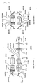


Classifications
-
- H—ELECTRICITY
- H04—ELECTRIC COMMUNICATION TECHNIQUE
- H04N—PICTORIAL COMMUNICATION, e.g. TELEVISION
- H04N9/00—Details of colour television systems
- H04N9/12—Picture reproducers
- H04N9/31—Projection devices for colour picture display, e.g. using electronic spatial light modulators [ESLM]
- H04N9/3102—Projection devices for colour picture display, e.g. using electronic spatial light modulators [ESLM] using two-dimensional electronic spatial light modulators
- H04N9/3111—Projection devices for colour picture display, e.g. using electronic spatial light modulators [ESLM] using two-dimensional electronic spatial light modulators for displaying the colours sequentially, e.g. by using sequentially activated light sources
- H04N9/3117—Projection devices for colour picture display, e.g. using electronic spatial light modulators [ESLM] using two-dimensional electronic spatial light modulators for displaying the colours sequentially, e.g. by using sequentially activated light sources by using a sequential colour filter producing two or more colours simultaneously, e.g. by creating scrolling colour bands
-
- G—PHYSICS
- G03—PHOTOGRAPHY; CINEMATOGRAPHY; ANALOGOUS TECHNIQUES USING WAVES OTHER THAN OPTICAL WAVES; ELECTROGRAPHY; HOLOGRAPHY
- G03B—APPARATUS OR ARRANGEMENTS FOR TAKING PHOTOGRAPHS OR FOR PROJECTING OR VIEWING THEM; APPARATUS OR ARRANGEMENTS EMPLOYING ANALOGOUS TECHNIQUES USING WAVES OTHER THAN OPTICAL WAVES; ACCESSORIES THEREFOR
- G03B21/00—Projectors or projection-type viewers; Accessories therefor
- G03B21/14—Details
- G03B21/20—Lamp housings
- G03B21/208—Homogenising, shaping of the illumination light
-
- G—PHYSICS
- G02—OPTICS
- G02B—OPTICAL ELEMENTS, SYSTEMS OR APPARATUS
- G02B27/00—Optical systems or apparatus not provided for by any of the groups G02B1/00 - G02B26/00, G02B30/00
- G02B27/28—Optical systems or apparatus not provided for by any of the groups G02B1/00 - G02B26/00, G02B30/00 for polarising
- G02B27/283—Optical systems or apparatus not provided for by any of the groups G02B1/00 - G02B26/00, G02B30/00 for polarising used for beam splitting or combining
-
- H—ELECTRICITY
- H04—ELECTRIC COMMUNICATION TECHNIQUE
- H04N—PICTORIAL COMMUNICATION, e.g. TELEVISION
- H04N9/00—Details of colour television systems
- H04N9/12—Picture reproducers
- H04N9/31—Projection devices for colour picture display, e.g. using electronic spatial light modulators [ESLM]
- H04N9/3197—Projection devices for colour picture display, e.g. using electronic spatial light modulators [ESLM] using light modulating optical valves
Definitions
- the present invention relates to a display device for irradiating illumination light emitted from a light source onto display elements, thereby displaying images, and more specifically, to a projector for making illumination light that is modulated by a plurality of pixels incident on a projection lens of the display element and projecting images from the projection lens to a screen, thereby displaying the images.
- a structure wherein a region onto which illumination light is irradiated to a display element is scanned by intermittently turning on and off a plurality of light sources arranged on the rear face of the display element (For example, refer to Patent Document 1.).
- a structure is also known wherein an illuminated region is scanned to a display element by rotating a condensing barrel that has a slit for determining the direction in which light sources emit light (For example, refer to Patent Document 2.).
- the angle of illumination light incident on the display element varies according to the illuminated position in the display element. Therefore, it is not possible to scan the illumination light to the display element while maintaining a uniform incidence angle of illumination light. Since it is not possible to illuminate the entire region to be illuminated in the same state, it is difficult to display images with uniform image quality.
- an object of the present invention is to provide a display device and a projector capable of improving the image quality of dynamic images, reducing limitations on light sources, improving the utilization efficiency of light, and displaying images in full color.
- a display device comprises: a light source for emitting illumination light; a display element having a plurality of pixels for modulating the illumination light; an irradiation optical system for irradiating illumination light emitted from the light source onto some of the pixels; and illumination light scanning means for scanning the illumination light irradiated by the irradiation optical system.
- the irradiation optical system comprises image forming means for condensing the illumination light emitted by the light source to form an image and image re-forming means for forming the image formed by the image forming means on the display element.
- Illumination light irradiated onto the display element is irradiated onto the display element by at least the image forming means and the image re-forming means.
- the display device comprises an irradiation optical system for irradiating illumination light onto some pixels of the display element and the illumination light scanning means for scanning the illumination light irradiated by the irradiation optical system
- illumination light is not instantaneously irradiated onto only some pixels of the display element by the irradiation optical system.
- the illumination light scanning means scans illumination light in a certain range of time. Therefore, it is possible to irradiate illumination light having a uniform illumination distribution onto all of the pixels of the display element. As a result, human eyes can sense the images displayed on the entire display element. At this time, when attention is paid to some pixels, illumination light sometimes reaches the pixels and sometimes does not reach the pixels.
- intermittent image display occurs.
- a hold type display element for displaying light having the brightness required for displaying an image on every pixel for predetermined time or a time integration type display element for modulating illumination light irradiated for predetermined time every time and displaying the illumination light on every pixel is used, it is possible to intermittently display images according to the structure of the present invention. Therefore, it is possible to reduce the blurriness of dynamic images caused by the display element by simply displaying continuous images, and to improve the quality of dynamic images.
- the present invention is useful in cases where dynamic images are to be displayed using as a display element a spatial light modulation element such as a liquid crystal panel for modulating illumination light and thereby displaying images onto a display element.
- the irradiation optical system includes image forming means for condensing illumination light emitted from the light sources, thereby forming an image, and image re-forming means for forming the image formed by the image forming means on the display element. Illumination light irradiated onto the display element is irradiated by at least the image forming means and the image re-forming means.
- a surface on which the image formed by the image forming means is formed is a shared surface that forms an image formation region (a region in which a plurality of pixels capable of modulating illumination light are formed) of the display element. Therefore, it is also possible to form an image in a specific pixel by changing the shape or the magnitude of beams of illumination light emitted from the light sources, thereby forming an image by the image forming means, and by re-forming the image on the display element by the image re-forming means. In particular, since it is possible to effectively irradiate illumination light to a specific pixel without limiting the illumination light by the light-shielding member, etc., it is possible to use almost partial light from the light sources, with small loss of light.
- the illumination light is irradiated onto some pixels of the display element means that an illuminated region and a non-illuminated region capable of improving the image quality of dynamic images by intermittent turning-on exists in the image formation region of the display element in a certain ratio.
- the shape of the image formation region illuminated by illumination light, or the distribution of the brightness of illumination light is not limited.
- the illumination light scanning means comprises a rotating prism for changing the refracting angle of the illumination light by the rotation thereof, thereby scanning the illumination light, and the position of an image formed by the image forming means is positioned inside or around the rotating prism.
- the diameter of beams of illumination light is very small in the image forming position in order to condense illumination light emitted from the light sources and to form an image. Therefore, when an image formed by the image forming means exists inside or around a rotating prism, the rotating prism can effectively transmit light, although the rotating prism is unnecessarily large. Therefore, it is possible to design the rotating prism to be small by controlling the refractive index of the rotating prism and thereby to miniaturize and lighten the display device. Also, since the rotating prism changes the refracting angle of the illumination light, thereby scanning the illumination light while rotating, it is possible to scan the illumination light while shifting the optical axis thereof in parallel.
- a projector according to the present invention comprises projecting means for projecting images of the display element in the above-mentioned display device.
- illumination light is divided into two or more colored light components after passing through the illumination light scanning means, and the image re-forming means is arranged in each colored light component and forms the image formed by the image forming means on the display element corresponding to each colored light component.
- illumination light is divided into a plurality of colored light components, it is possible to display images in full color, without color filters when the respective colored light components are modulated, thereby forming image light by the display elements corresponding to the respective light components.
- the image re-forming means are arranged to correspond to the respective colored light components, it is possible to correctly irradiate illumination light onto some pixels of the respective display elements when the image forming position is controlled by the image re-forming means even though the distances from the light sources to the display elements corresponding to the respective colored light components are different from each other, thereby easily reducing the slowness of dynamic images.
- the illumination light is divided into two or more colored light components after passing through the illumination light scanning means, it is possible to improve the quality of dynamic images while displaying images in full color even if there is one illumination light scanning means.
- illumination light emitted from the light source is divided into two or more colored light components
- the image re-forming means and the illumination light scanning means are arranged in each colored light component
- the image re-forming means forms the image formed by the image forming means on the display element corresponding to each colored light component
- the illumination light scanning means scans the illumination light divided into respective colored light components so that the projected positions of the images formed by the image re-forming means are almost the same when the images of the display elements corresponding to the respective colored light components are projected so as to be overlapped.
- illumination light can be divided into a plurality of colored light components, it is possible to display images in full color without color filters when the respective colored light components are modulated, thereby forming image light by the display elements corresponding to the respective colored light components.
- image re-forming means corresponding to the respective colored light components are arranged, it is possible to correctly irradiate illumination light onto some pixels of the respective display elements when the image forming position is controlled by the image re-forming means, even though the distances from the light sources to the display elements corresponding to the respective colored light components are different from each other, and thereby easily reduce the slowness of dynamic images.
- the illumination light scanning means can intermittently display images in the respective colors to which the images of the display elements are repeatedly projected in order to scan the illumination light divided into respective colored light components so that the projected positions of the images formed by the image re-forming means are uniform when the images of the display elements corresponding to the respective colored light components are repeatedly projected. Therefore, it is possible to reduce the slowness of dynamic images caused by the display element by simply displaying continuous images, and to obtain optimal images, without the flickering of colors in which colors are divided.
- the illumination light scanning means are arranged in each colored light component, it is possible to optimize the position and the material of the illumination light scanning means and the coating of the surface of the illumination light scanning means in each colored light component, with consideration to the deviation in image forming states dependent on the wavelengths of the respective colored light components. Therefore, it is possible to more correctly irradiate illumination light onto some pixels of the respective display elements and thereby easily reduce the slowness of dynamic images.
- illumination light emitted from the light source is divided into two or more colored light components
- the image re-forming means and the illumination light scanning means are arranged in each colored light component, at least one component of the colored light is divided into two or more colored light components after passing through the illumination light scanning means
- the image re-forming means forms the image formed by the image forming means on the display element corresponding to each colored light component
- the illumination light scanning means scans the illumination light divided into respective colored light components so that the projected positions of the images formed by the image re-forming means are almost the same when the images of the display elements corresponding to the respective colored light components are projected so as to be overlapped.
- the illumination light scanning means are arranged in each colored light component, it is possible to optimize the position and the material of the illumination light scanning means and the coating of the surface of the illumination light scanning means in each colored light component, with consideration to the deviation in image forming states dependent on the wavelengths of the respective colored light components. Furthermore, since at least one colored light component of the illumination light divided into respective colored light components is divided into two or more colored light components after passing through the illumination light scanning means, only one illumination light scanning means is provided in the colored light component divided after passing through the illumination light scanning means. Therefore, it is possible to design an optical system in which the number of illumination light scanning means is as small as possible, with consideration to the deviation in image forming states, dependent on the wavelengths of the respective colored light components by arranging the illumination light scanning means in each colored light component.
- the distances from the light source to the display elements corresponding to the respective colored light components are almost the same for each colored light component.
- the distances from the light source to the positions of the images of the respective colored light components formed by the image forming means are almost the same for each colored light component.
- the distances from the positions of the images of the respective colored light components, which are formed by the image forming means, to the display elements corresponding to the respective colored light components are almost the same for each colored light component.
- the distances from the positions of the images of the respective colored light components formed by the image forming means, to the display elements corresponding to the respective colored light component are almost the same for each colored light component, it is possible to correctly irradiate illumination light onto some pixels of the respective display elements in a structure where the illumination light is divided into a plurality of colored light components between the light sources and the illumination light scanning means and thereby easily improve the utilization efficiency of light and reduce the slowness of dynamic images.
- some parts of the image re-forming means may be shared. As a result, it is possible to reduce the number of parts by sharing some parts of the image re-forming means. It is possible to correct the deviation in image forming states dependent on the wavelengths of the respective colored light components in each colored light component by using the parts of the image re-forming means of the respective colored light components that are not shared.
- the display device and the projector according to the present invention comprise an irradiation optical system for irradiating the illumination light onto some pixels of the display element, and illumination light scanning means for scanning the illumination light irradiated by the irradiation optical system, illumination light is not instantaneously irradiated onto only some pixels of the display element by the irradiation optical system.
- the illumination light scanning means irradiates the illumination light in a certain range of time. Therefore, it is possible to irradiate illumination light having a uniform illumination distribution onto all of the pixels of the display element.
- human eyes can sense the images displayed on the entire display element. At this time, when attention is paid to some pixels, illumination light sometimes reaches the pixels and sometimes does not reach the pixels.
- the phenomenon known as intermittent display occurs.
- the hold type display element for displaying light having brightness required for displaying an image on every pixel for predetermined time or a time integration type display element for modulating illumination light irradiated for predetermined time every time and displaying the illumination light on every pixel is used, it is possible to intermittently display images according to the structure of the present invention. Therefore, it is possible to reduce the slowness of dynamic images caused by the display element by simply displaying continuous images, and to improve the quality of dynamic images. Also, since it is not necessary to intermittently turn light sources on and off, and to arrange a plurality of light sources in a plane for uniform illumination, limitations on the light sources are small.
- the irradiation optical system comprises image forming means for condensing illumination light emitted from the light sources, thereby forming an image, and image re-forming means for forming the image formed by the image forming means on the display element.
- Illumination light irradiated onto the display element is irradiated onto the display element by at least the image forming means and the image re-forming means. Therefore, if only an image in which the illumination light can be irradiated onto specific pixels by such an illumination optical system is formed, it is possible to effectively irradiate illumination light onto specific pixels without limiting the illumination light by the light-shielding member and thereby to reduce the loss of light and to use partial light components from the light sources. Therefore, it is possible to realize a display device and a projector capable of improving the utilization efficiency of light.
- the distances from the light sources to the optical parts are almost the same for each colored light component in the projector where illumination light is divided into two or more colored light components. Therefore, it is possible to realize a structure in which the respective colored light components are correctly irradiated onto the display elements when the illumination region are the same size and the scanning directions of the respective colored light components are the same. As a result, it is possible to improve the quality of dynamic images and the utilization efficiency of light and to display images in full color. Also, it is possible to share optical parts, and thereby reduce the number of parts by making the distances from the light sources to the optical parts almost the same for each colored light component in the projector where illumination light is divided into two or more colored light components.
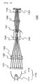
- FIG. 1 illustrates a display device according to embodiment 1 of the present invention.
- a display device 100 comprises a light source lamp 110 (a light source), fly eye lenses 121 and 122, a superposing lens 123, a collimating lens 124 (image forming means), a rotating prism 130 (illumination light scanning means), image re-forming lenses 141, 142, and 143 (image re-forming means), and a liquid crystal light valve 150 (a display element).
- the light source lamp 110 includes a lamp 111 that serves as a light source and a concave mirror 112.
- the lamp 111 comprises, for example, a discharge lamp such as a high-pressure mercury lamp.
- the concave mirror 112 comprises a parabolic mirror.
- the structures of the lamp 111 and the concave mirror 112 are not limited thereto and can be appropriately modified. Furthermore, it is not necessary to intermittently turn on and off the lamps that serve as light sources and to arrange a plurality of lamps in a plane for uniform illumination.
- the lamp 111 emits illumination light and the concave mirror 112 reflects the illumination light to the fly eye lenses 121 and 122.
- a condensing lens is used instead of a concave mirror 112 to emit the illumination light to the fly eye lenses 121 and 122, or structures for emitting illumination light or a plurality of light sources are arranged in an array.
- the kinds, the number, and the structures of light sources may be appropriately modified.
- the fly eye lenses 121 and 122 are a lens array in which micro-lenses having rectangular outlines are arranged in a matrix.
- the appearance of each micro-lens is formed such that the ratio thereof is exchanged with the ratio of the appearance of the image formation region (the region comprising a plurality of pixels capable of modulating illumination light) of the liquid crystal light valve 150 that is the display element seen from the main optical axis of the optical system.
- the appearance of the image formation region of the liquid crystal light valve 150 is a rectangle in which the aspect ratio is 4:3.
- each micro-lens is a rectangle in which the aspect ratio is 4:1.
- the fly eye lens 121 divides illumination light emitted from the light sources into a plurality of partial light components that are condensed by the respective micro-lenses of the fly eye lens 122.
- the fly eye lens 122 makes the plurality of divided partial light components incident on the superposing lens 123.
- the superposing lens 123 condenses the plurality of divided partial light components through the collimating lens 124 and forms an image defined by the appearances of the micro-lenses of the fly eye lens 121 inside the rotating prism 130.
- the image is formed on a plane including the rotation axis of the rotating prism 130. Therefore, the diameter of beams of illumination light that has past through the rotating prism 130 becomes very small. As a result, illumination light effectively passes through the rotating prism 130.
- the image formed by the fly eye lenses 121 and 122, the superposing lens 123, and the collimating lens 124 that are the image forming means may be around the rotating prism 130 instead of inside the rotating prism 130. The position of the image is not limited thereto as long as the rotating prism 130 effectively transmits light.
- the rotating prism 130 When the rotating prism 130 rotates, the optical distances of the respective rays that constitute illumination light change depending to the rotation states of the rotating prism 130. Therefore, the image forming position partially is displaced back and forth. As a result, when the whole optical system is designed, it is preferable to set the position of the image formed inside or around the rotating prism 130, with consideration to the rotating state so that the image formed on the display element 150 is optimal. That is, it is possible to appropriately set the relationship between the rotation state of the rotating prism 130 and the image forming position by designing the optical system based on the position of the image formed in a state of being rotated by 45° other than on the rotating position of the rotating prism 130 as illustrated in Fig. 1.
- the image re-forming lenses 141, 142, and 143 are the image re-forming means for forming the image formed by the fly eye lenses 121 and 122, the superposing lens 123, and the collimating lens 124 that are the image forming means on the liquid crystal light valve 150 that is an display element. Since the image re-forming means are for forming the image formed by the image forming means on the display element, the image re-forming means may be combinations of curved mirrors instead of lenses. Furthermore, the number of lenses or curved mirrors, the magnification and the reduction ratio of an image, and the aspect ratios can be appropriately modified.
- the image re-forming means relays the image by forming the image several times. That is, the number of times by which an image is formed by the image re-forming means is not limited to one time.
- the fly eye lenses 121 and 122, the superposing lens 123, and the collimating lens 124 forms an image inside the rotating prism 130 by changing the shape or the size of beams of illumination light emitted from the light source 110.
- the image re-forming lenses 141, 142, and 143 re-form the image formed by the fly eye lenses 121 and 122, the superposing lens 123, and the collimating lens 124 on the display element.
- the irradiation optical system including the fly eye lenses 121 and 122, the superposing lens 123, and the collimating lens 124 that are the image forming means and the image re-forming lenses 141, 142, and 143 that are the image re-forming means. That is, the aspect ratio of the image formation region of the liquid crystal light valve 150 is 4:3, whereas the aspect ratio of the appearance of the fly eye lens 121 is 4:1. Therefore, it is possible to irradiate illumination light having a uniform illumination distribution onto the portion corresponding to 1/3 of the image formation region.
- the region (the image formed by the image re-forming means) illuminated by the irradiation optical system is designed to be larger than the size of the image formation region in its horizontal direction (the direction perpendicular to the scanning direction) at any moment, it does not depart from the scope of the present invention as long as the region illuminated by the irradiation optical system is narrower region than the size of the image formation region in its vertical direction (the direction parallel to the scanning direction).
- the rotating prism 130 is arranged as illumination light scanning means for scanning the illumination light, illumination light passes through the rotating prism 130 while the optical axis thereof is shifted. Therefore, the illumination position of the image formation region of the liquid crystal light valve 150 changes. Also, the rotating prism 130 comprising a quadratic pillar prism made of a glass material changes the refracting angle of the illumination light by the rotation thereof, thereby serving to scan the illumination light.
- the rotating prism 130 connected to an electronic motor (not shown) rotates while the rotation speed thereof is controlled.
- Fig. 2 illustrates the operation of the rotating prism 130 in detail.
- Fig. 2 a case in which the rotating prism 130 rotates counter-clockwise about the axis thereof perpendicular to the sheet will be described.
- the rotation position of the rotating prism 130 illustrated in Fig. 2(a) is the position in which the illumination light incident from the left of the drawing on the rotating prism 130 goes straight without being refracted and is emitted.
- the illumination light is described to be light rays parallel to the main optical axis of the optical system for the simplicity of description. Hereinafter, illumination light is described as rays.
- the rotation position of the rotating prism 130 illustrated in Fig. 2(b) is between 0° and 45° from the rotation position illustrated in Fig. 2(a) counter-clockwise.
- the illumination light incident from the left side of the drawing on the rotating prism 130 is refracted upward in the drawing and is emitted from the right side of the drawing.
- the rotation position of the rotating prism 130 illustrated in Fig. 2(c) is between 45° and 90° from the rotation position illustrated in Fig. 2(a) in the counter-clockwise direction.
- the illumination light incident from the left side of the drawing on the rotating prism 130 is refracted downward in the drawing and is emitted from the right side of the drawing.
- the rotation position of the rotating prism 130 illustrated in Fig. 2(d) is 90° from the rotation position illustrated in Fig. 2(a) in the counter-clockwise direction.
- the illumination light incident from the left side of the drawing on the rotating prism 130 is straightened, without being refracted, and is emitted as illustrated in Fig. 2(a).
- illumination light passes through the rotating prism 130, while the optical axis thereof is shifted in parallel in accordance with the relationship between the rotation of the rotating prism 130 and the refractive index.
- illumination light that has past through the rotating prism 130 is incident on the liquid crystal light valve 150 that is the display element through the image re-forming lenses 141, 142, and 143.
- the illumination light is irradiated while being scanned inside the image formation region of the liquid crystal light valve 150.
- Fig. 3 illustrates the scanning of the illumination light inside the image formation region of the liquid crystal light valve 150 by the rotation of the rotating prism 130.
- the illumination light irradiation regions illustrated in Figs. 3(a) to 3(d) correspond to the rotation positions of the rotating prism 130, which are illustrated in Figs. 2(a) to 2(d). Since the image re-forming lenses 141, 142, and 143 are arranged between the rotating prism 130 and the liquid crystal light valve 150, the scanning direction of Fig. 3 is inverse to the scanning direction of Fig. 2.
- Fig. 3(e) illustrates the illumination state integrated for a certain time period when illumination light is continuously and repeatedly irradiated onto the inside of the image formation region of the liquid crystal light valve 150 illustrated in Figs. 3(a) to 3(d).
- illumination light that has past through the rotating prism 130 in the rotation position of Fig. 2(a) is irradiated onto some pixels of the liquid crystal light valve 150, that is, the portion corresponding to 1/3 of the image formation region in the center of the image formation region.
- the rotating prism 130 rotates as illustrated in Figs. 2(a) and 2(b)
- the irradiation region is transited so that the illumination light starts to be irradiated from the center of the image formation region of the liquid crystal light valve 150, as illustrated in Figs. 3(a) to 3(b).
- the rotating prism 130 rotates as illustrated in Figs.
- irradiation region is transited so that the illumination light starts to be irradiated from the upper end of the image formation region of the liquid crystal light valve 150, as illustrated in Figs. 3(b) to 3(c).
- the rotating prism 130 rotates as illustrated in Figs. 2(c) to 2(d), as illustrated in Figs. 3(c) to 3(d)
- the irradiation region is transited from the upper end to the center of the image formation region of the liquid crystal light valve 150.
- the direction in which electric signals that are the image data of the liquid crystal light valve 150 are written preferably corresponds to the direction to which illumination light is scanned.
- the period in which the electric signals that are the image data is written down is preferably almost the same as the scanning period of scanning.
- the illumination light is preferably irradiated after enough image data are written in the respective pixels.
- the illumination region is integrated for a certain period of time as illumination light is repeatedly scanned to the inside of the image formation region of the liquid crystal light valve 150 at high speed, as illustrated in Fig. 3(e), it is possible to irradiate illumination light having a uniform illumination distribution onto the inside of the image formation region.
- the illumination light sometimes reaches the pixels and sometimes does not reach the pixels. Therefore, the phenomenon known as the intermittent display occurs.
- the intermittent display occurs.
- the size of the illumination region in the image formation region (the size of the image formed by the image re-forming means) is not limited to the above and can be appropriately modified; however, it is preferably as narrow as possible in a range where the entire image formation region is illuminated by scanning. This is because it is possible to further reduce the slowness of dynamic images since it is possible to more intermittently display the images.
- the area of the illumination region is preferably no more than 1/2 of the area of the image formation region.
- the liquid crystal light valve 150 has a structure in which polarizers are included in front of and behind the liquid crystal light valve 150 and red, green, and blue color filters are regularly arranged in each of a plurality of pixels that form the image formation region of the liquid crystal light valve 150. Therefore, when illumination light incident on the image formation region of the liquid crystal light valve 150 is modulated in each pixel based on electric signals that become the image data, an image is finally displayed on the liquid crystal light valve 150 in full color.
- the image displayed on the liquid crystal light valve 150 may be projected to a screen (not shown) by arranging a projection lens 160 (projection means) having almost the same structure as that of the display device 100 of the projector 101 illustrated in Fig. 4.
- the image may be projected from the front or rear surface of the screen. Curved mirrors rather than the projection lenses 150 may be used as the projection means.
- the display device 100 or the projector 101 comprises the light source for emitting illumination light, a liquid crystal light valve 150 having the plurality of pixels capable of modulating the illumination light, a irradiation optical system for irradiating illumination light emitted from the light source onto some pixels of the liquid crystal light valve 150, and a rotating prism 130 for scanning the illumination light irradiated by the irradiation optical system.
- the irradiation optical system includes fly eye lenses 121 and 122, a superposing lens 123 and a collimating lens 124 as the image forming means for condensing illumination light emitted from the light source, thereby forming an image, and image re-forming lenses 141, 142, and 143 as the image re-forming means for forming the image formed by the image forming means on the liquid crystal light valve. Only a part of the image formation region of the liquid crystal light valve is instantaneously illuminated by the irradiation optical system with a uniform illumination distribution.
- the illumination light irradiation means scans the illumination light inside the image formation region for a certain range of time, the illumination light having a uniform illumination distribution is irradiated onto the entire image formation region. Therefore, human eyes can sense the image. When attention is paid to some pixels of the image formation region, illumination light sometimes reaches the pixels and sometimes does not reach the pixels. Therefore, the phenomenon known as the intermittent display may occur. As a result, even when a hold type display element using liquid crystal is used, it is possible to intermittently display images. Therefore, it is possible to reduce the slowness of dynamic images caused by the hold type display element by simply displaying continuous images, and thereby to improve the quality of dynamic images.
- the image formed by condensing illumination light emitted from the light sources is formed on the display element by the image re-forming means in the irradiation optical system, it is possible to effectively irradiate illumination light emitted from the light sources onto specific pixels and thereby to reduce the loss of light. As a result, it is possible to use almost all of the light components emitted from the light sources.
- fly eye lenses 121 and 122, a superposing lens 123, and a collimating lens 124 are used as the image forming means.
- a image forming lens that forms the image formed by the fly eye lenses 121 and 122, the superposing lens 123, and the collimating lens 124 may be used as the image forming means.
- the image re-forming means for forming the image formed by the fly eye lenses 121 and 122, the superposing lens 123, the collimating lens 124, and the image forming lens on the display element. That is, the number of times by which the image is formed by the image forming means is not limited to one time.
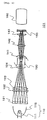
- FIG. 5 illustrates a projector according to embodiment 2 of the present invention.
- a projector 200 comprises a light source lamp 110, fly eye lenses 121 and 122, a superposing lens 123, a collimating lens 124, a rotating prism 130, a color dividing dichroic prism 271, reflecting mirrors 281R, 282R, 281B, and 282B, image re-forming lenses 241R, 242R, 243R, 241G, 242G, 243G, 241B, 242B, and 243B, liquid crystal light valves 250R, 250G, and 250B, a color synthesizing dichroic prism 272, and a projection lens 260.
- the components of illumination light emitted from the light sources are displayed by respective divided colored light components.
- the respective colored light components are illustrated in Fig. 5 as rays parallel to the main optical axis of the optical system.
- the distance from the light source 110 to the rotating prism 130 in Fig. 5 is the same as that in Fig. 1.
- Fig. 5 is obtained by rotating Fig. 1 by 90° using the main optical axis of the optical system as a rotation axis.
- illumination light emitted from the light source lamp 110 passes through the fly eye lenses 121 and 122 and the superposing lens 123.
- the superposing lens 123 condenses a plurality of divided partial light components and forms the image defined by the appearance of the micro-lens of the fly eye lens 121 through the collimating lens 124 inside the rotating prism 130. Meanwhile the aspect ratio of the image formation regions of the liquid crystal light valves 250R, 250G, and 250B is 4:3, the aspect ratio of the appearance of each micro-lens is 4:1.
- Illumination light that has past through the rotating prism 130 is incident on the color dividing dichroic prism 271.
- the color dividing dichroic prim 271 consisted of four triangular prisms bonded to each other forms an optical multi-layered film for reflecting red colored light to the surface to which the triangular prisms are bonded, thereby transmitting green colored light, and an optical multi-layered film for reflecting blue colored light, thereby transmitting green colored light, divides incident illumination light into red colored light, green colored light, and blue colored light, and separately emits respective colored light components in three directions. Therefore, illumination light incident on the color dividing dichroic prism 271 is divided into red colored light 290R, green colored light 290G, and blue colored light 290B. Therefore, illumination light emitted from the light source 110 is divided into two or more colored light components after passing through the rotating prism that is the illumination scanning means.
- optical parts with the same color dividing function may be used as the color dividing dichroic prism in which two glass plates having the same optical multi-layered films cross each other.
- red colored light 290R is guided to the liquid crystal light valve 250R by reflecting mirrors 281R, and 282R and image re-forming lenses 241R, 242R, and 243R.
- the image re-forming lenses 241R, 242R, and 243R form the image formed by the fly eye lenses 12-1 and 122, the superposing lens 123, and the collimating lens 124 that are the image forming means on the liquid crystal light valve 250R that is the display element.
- Green colored light 290G is guided to the liquid crystal light valve 250G by the image re-forming lenses 241G, 242G, and 243G.
- the image re-forming lenses 241G, 242G, and 243G form the image formed by the fly eye lenses 121 and 122, the superposing lens 123, and the collimating lens 124 that are the image forming means on the liquid crystal light valve 250G that is the display element.
- Blue colored light 290B is guided to the liquid crystal light valve 250B by the reflecting mirrors 281B and 282B and the image re-forming lenses 241B, 242B, and 243B.
- the image re-forming lenses 241B, 242B, and 243B form the image formed by the fly eye lenses 121 and 122, the superposing lens 123, and the collimating lens 124 that are the image forming means on the liquid crystal light valve 250B that is the display element.
- illumination light having a uniform illumination distribution onto the portion corresponding to 1/3 of the image formation region of each of the liquid crystal light valves 250R, 250G, and 250B. Since the rotating prism 130 as illumination light scanning means is arranged, illumination light passes through the rotating prism while the optical axis thereof is shifted in accordance with the relationship between the rotation of the rotating prism and the refractive index. Therefore, the respective divided colored light components are uniformly irradiated onto all of the image formation regions while scanning all of the image formation regions of the respective liquid crystal light valves 250R, 250G, and 250B.
- the respective colored illumination light components incident on the image formation regions of the liquid crystal light valves 250R, 250G, and 250B are modulated based on electric signals in the image formation regions of the liquid crystal light valves 250R, 250G, and 250B and are guided to the projection lens by the color synthesizing dichroic prism 272.
- the dichroic prism 272 consisted of four triangular prisms bonded to each other, forms an optical multi-layered film for reflecting red colored light to the surface to which the four triangular prisms are bonded, thereby transmitting the green colored light and an optical multi-layered film for reflecting the blue colored light, thereby transmitting green colored light, synthesizes the red colored light, the green colored light, and the blue colored light separately incident from three directions, and emits the synthesized light to the projection lens 260.
- Each of the liquid crystal light valves 250R, 250G, and 250B has a structure in which two polarizers are arranged in front of and behind the liquid crystal light valve. However, the red, green, and blue color filters are not arranged in each pixel as in embodiment 1.
- Illumination light incident on the projection lens is projected to a screen (not shown), thereby displaying an image to the screen.
- a screen not shown
- the images of the liquid crystal light valves 250R, 250G, and 250B for modulating red colored light, green colored light, and blue colored light overlap on the screen, it is possible to display the images in full color.
- the positions of the images corresponding to the respective colored light components, which are formed by a group of image re-forming lenses, are the same.
- an image formed by the image re-forming lens is formed in the center of the image formation region of the liquid crystal light valve 250R at any moment, an image formed by the image re-forming lenses is also formed in the center of the image formation region of the liquid crystal light valve 250G or the liquid crystal light valve 250B.
- the scanning directions or speed of the images corresponding to the respective colored light components are the same.
- the projector 200 comprises the light source for emitting illumination light, the liquid crystal light valves 250R, 250G, and 250B having a plurality of pixels for modulating the illumination light, an irradiation optical system for irradiating illumination light emitted from the light source onto some pixels of the liquid crystal light valves 250R, 250G, and 250B, and the rotating prism 130 for scanning the illumination light irradiated by the irradiation optical system.
- the irradiation optical system includes fly eye lenses 121 and 122, a superposing lens 123, and a collimating lens 124 as the image forming means for condensing illumination light emitted from the light source, thereby forming an image, and image re-forming lenses 241R, 242R, 243R, 241G, 242G, 243G, 241B, 242B, and 243B as the image re-forming means for forming the image formed by the image forming means on the liquid crystal light valves.
- a projector capable of improving the quality of dynamic images, of reducing limitations on the light sources, of improving the utilization efficiency of light, and of displaying images in full color without using color filters.
- the illumination light is divided into two or more colored light components after passing through the rotating prism 130 that is the illumination light scanning means.
- the image re-forming lens arranged in each colored light component forms the image formed by the fly eye lenses 121 and 122, the superposing lens 123, and the collimating lens 124 that are the image forming means on the liquid crystal light valves 250R, 250G, and 250B corresponding to the respective colored light components. Therefore, it is possible to surely irradiate illumination light onto some pixels of each liquid crystal light valve by the image re-forming lens arranged in each colored light component although the distances from the light sources to the liquid crystal light valves corresponding to the respective colored light components are different from each other. As a result, it is possible to reduce the slowness of dynamic images and to improve the utilization efficiency of light.
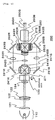
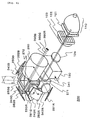
- Fig. 6 is a perspective view of a projector according to embodiment 3 of the present invention.
- the projector 300 comprises a light source lamp 110, fly eye lenses 121 and 122, a superposing lens 123, a collimating lens 124, a rotating prism 130, a color dividing dichroic prism 271, reflecting mirrors 381R, 382R, 381G, 382G, 381B, and 382B, image re-forming lenses 341, 342R, 343R, 342G, 343G, 342B, and 343B, liquid crystal light valves 250R, 250G, and 250B, a color synthesizing dichroic prism 272, and a projection lens 260.
- Embodiment 3 is different from embodiment 2 in that the axis on which the color dividing surfaces of the color dividing dichroic prism 271 cross each other overlaps the axis on which the color synthesizing surfaces of the color synthesizing dichroic prism 272 cross each other, so that the two axes are arranged on the same axis and that some parts of the image re-forming lenses arranged in the respective colored light components are shared.
- Fig. 7(a) is a sectional view of the projector 300, which is taken along the plane including the plane A in Fig. 6.
- Fig. 7(b) is a sectional view of the projector 300, which is taken along the plane including the plane B in Fig. 6.
- the components of illumination light emitted from the light sources are displayed by respective divided colored light components.
- the respective colored light components are described in Fig. 7 as rays parallel to the main optical axis of the optical system.
- illumination light emitted from the light source lamp 110 passes through the fly eye lenses 121 and 122 and the superposing lens 123.
- the superposing lens 123 condenses a plurality of divided partial light components and forms the image defined by the appearance of the micro-lens of the fly eye lens 121 through the collimating lens 124 inside the rotating prism 130. Meanwhile the aspect ratio of the image formation regions of the liquid crystal light valves 250R, 250G, and 250B is 4:3, the aspect ratio of the appearance of each micro-lens is 4:1.
- Illumination light that has past through the rotating prism 130 is incident on the color dividing dichroic prism 271 via the image re-forming lens 341.
- Illumination light incident on the color dividing dichroic prism 271 is divided into red colored light 390R, green colored light 390G, and blue colored light 390B.
- Red colored light 390R is guided to the liquid crystal light valve 250R by the reflecting mirrors 381R and 382R and the image re-forming lenses 342R and 343R on a roughly U-shaped optical path.
- the image re-forming lenses 341, 342R, and 343R form the image formed by the fly eye lenses 121 and 122, the superposing lens 123, and the collimating lens 124 that are the image forming means on the liquid crystal light valve 250R that is the display element.
- Green colored light 390G is guided to the liquid crystal light valve 250G by the reflecting mirrors 381G and 382G and the image re-forming lenses 342G and 343G on the roughly U-shaped optical path.
- the image re-forming lenses 341, 342G, and 343G form the image formed by the fly eye lenses 121 and 122, the superposing lens 123, and the collimating lens 124 that are the image forming means on the liquid crystal light valve 250G that is the display element.
- Blue colored light 390B is guided to the liquid crystal light valve 250B by the reflecting mirrors 381B and 382B and the image re-forming lenses 342B and 343B on the roughly U-shaped optical path.
- the image re-forming lenses 341, 342B, and 343B form the image formed by the fly eye lenses 121 and 122, the superposing lens 123, and the collimating lens 124 that are the image forming means on the liquid crystal light valve 250B that is the display element.
- illumination light having a uniform illumination distribution onto the portion corresponding to 1/3 of the image formation region of each of the liquid crystal light valves 250R, 250G, and 250B. Since a rotating prism 130 is arranged as illumination light irradiating means, illumination light passes through the rotating prism while the optical axis thereof is shifted in accordance with the relationship between the rotation of the rotating prism and the refractive index. Therefore, the respective divided colored light components are uniformly irradiated onto all of the image formation regions while scanning all of the image formation regions of the liquid crystal light valves 250R, 250G, and 250B.
- the respective colored illumination light components incident on the image formation regions of the liquid crystal light valves 250R, 250G, and 250B are modulated in the image formation regions of the liquid crystal light valves 250R, 250G, and 250B based on electric signals and are guided to the projection lens by the color synthesizing dichroic prism 272.
- Illumination light incident on the projection lens 260 is projected to a screen (not shown) thereby to display an image on the screen.
- a screen not shown
- the images of the liquid crystal light valves 250R, 250G, and 250B for modulating red colored light, green colored light, and blue colored light overlap on the screen, it is possible to display the images in full color.
- the positions of the images corresponding to the respective colored light components, which are formed by a group of image re-forming lenses, are the same.
- an image formed by the image re-forming lens is formed in the center of the image formation region of the liquid crystal light valve 250R at any moment, an image formed by the image re-forming lenses is also formed in the center of the image formation region of the liquid crystal light valve 250G or the liquid crystal light valve 250B.
- the scanning directions or speed of the images corresponding to the respective colored light components are the same.
- the projector 300 comprises a light source for emitting illumination light, liquid crystal light valves 250R, 250G, and 250B having a plurality of pixels for modulating the illumination light, an irradiation optical system for irradiating illumination light emitted from the light source onto some pixels of the liquid crystal light valves 250R, 250G, and 250B, and the rotating prism 130 for scanning the illumination light irradiated by the irradiation optical system.
- the irradiation optical system includes fly eye lenses 121 and 122, a superposing lens 123, and a collimating lens 124 as the image forming means for condensing illumination light emitted from the light source, thereby forming an image, and image re-forming lenses 341, 342R, 343R, 342G, 343G, 342B, and 343B as the image re-forming means for forming the image formed by the image forming means on the liquid crystal light valves.
- a projector capable of improving the quality of dynamic images, of reducing limitations on the light sources, of improving the utilization efficiency of light, and of displaying images in full color as in embodiment 2.
- the distances from the light sources to the liquid crystal light valves 250R, 250G, and 250B corresponding to the respective colored light components or the distances from the positions of the images of the respective colored light components, which are formed by the image forming means, to the liquid crystal light valves 250R, 250G, and 250B are almost the same in the respective colored light components, it is possible to irradiate illumination light divided into respective colored light components onto some pixels of the respective liquid crystal light valves with illumination regions of the same size. Therefore, even when the image re-forming lens 341 that is a part of the image re-forming means is shared, it matters little because the characteristics of the image re-forming lenses of the respective colored light components are similar to each other.
- the axis on which the color dividing surfaces of the color dividing dichroic prism 271 cross each other and the axis on which the color synthesizing surfaces of the color synthesizing dichroic prism 272 cross each other are arranged on the same axis, when almost the same optical parts are arranged in each colored light component, it is possible to make the shapes of the illumination regions of the respective colored light components almost the same and to make the scanning directions of the illumination light the same. Therefore, since optical parts for making the scanning directions the same are not necessary, it is possible to simply and compactly form the optical system.
- the image re-forming lens 341 is shared by the respective colored light components; however, it may not be shared as described in embodiment 2.
- the reflecting mirror whose optical path is bent may be appropriately arranged between the light source lamp 110 and the color dividing dichroic prism 271 so that the light source lamp 110 does not intercept the light projected from the projection lens 260.
- reflection type liquid crystal panels 351R, 351G, and 351B and polarization dividing prisms 383R, 383G, and 383B having polarization dividing surfaces for selectively transmitting or reflecting specific polarization light are arranged instead of liquid crystal light valves 250R, 250G, and 250B and reflecting mirrors 382R, 382G, and 382B. It is necessary to change the magnifications and the arrangement of the image re-forming lenses in accordance with such a structure.
- FIG. 9 illustrates a projector according to embodiment 4 of the present invention.
- a projector 400 comprises a light source lamp 110, fly eye lenses 421 and 422, a superposing lens 423, collimating lenses 424R, 424G, and 424B, rotating prisms 430R, 430G, and 430B, color dividing dichroic mirrors 471 and 472, reflecting mirrors 481, 482, 483, 484, and 485, image re-forming lenses 441R, 442R, 443R, 441G, 442G, 443G, 441B, 442B, and 443B, liquid crystal light valves 250R, 250G, and 250B, color synthesizing dichroic prism 272, and a projection lens 260.
- the components of illumination light emitted from the light sources are displayed by respective divided colored light components.
- the respective colored light components are described as rays parallel to the main optical axis of the optical system.
- illumination light emitted from the light source lamp 110 passes through the fly eye lenses 421 and 422 and the superposing lens 423.
- the aspect ratio of the image formation region of each of the liquid crystal light valves 250R, 250G, and 250B is 4:3, whereas the aspect ratio of the appearance of each micro-lens in the fly eye lenses is 4:1.
- Illumination light that has past through the superposing lens 423 is incident on the color dividing dichroic mirror 471 and is divided into red colored light 490R, green colored light 490G, and blue colored light 490B.
- the color dividing dichroic mirror 471 forms an optical multi-layered film for reflecting red colored light and transmitting green colored light and blue colored light, and divides incident illumination light into red colored light and green colored light, and blue colored light.
- Red colored light is reflected by the reflecting mirrors 481 and 482 and is incident on the rotating prism 430R through the collimating lens 424R.
- Green colored light and blue colored light are reflected by the reflecting mirror 483, are incident on the color dividing dichroic mirror 472, and are divided into green colored light and blue colored light.
- the color dividing dichroic mirror 472 forms an optical multi-layered film for reflecting the green colored light and transmitting the blue colored light and divides incident illumination light into green colored light and blue colored light.
- Green colored light is incident on the rotating prism 430G through the collimating lens 424G.
- Blue colored light is incident on the rotating prism 430B through the collimating lens 424B.
- the superposing lens 423 forms the image defined by the appearance of the micro-lens of the fly eye lens 421 on the inside of each of the rotating prisms 430R, 430G, and 430B.
- Red colored light 490R that has past through the rotating prism 430R is guided to the liquid crystal light valve 250R by the image re-forming lenses 441R, 442R, and 443R and the reflecting mirror 484.
- the image re-forming lenses 441R, 442R, and 443R form the image formed by the fly eye lenses 421 and 422, the superposing lens 423, and the collimating lens 424R that are the image forming means on the liquid crystal light valve 250R that is the display element.
- Green colored light 490G that has past through the rotating prism 430G is guided to the liquid crystal light valve 250G by the image re-forming lenses 441G, 442G, and 443G and the reflecting mirror 481.
- the image re-forming lenses 441G, 442G, and 443G form the image formed by the fly eye lenses 421 and 422, the superposing lens 423, and the collimating lens 424G that are the image forming means on the liquid crystal light valve 250G that is the display element.
- Blue colored light 490B that has past through the rotating prism 430B is guided to the liquid crystal light valve 250B by the image re-forming lenses 441B, 442B, and 443B and the reflecting mirror 485.
- the image re-forming lenses 441B, 442B, and 443B form the image formed by the fly eye lenses 421 and 422, the superposing lens 423, and the collimating lens 424B that are the image forming means on the liquid crystal light valve 250B that is the display element.
- the rotating prisms 430R, 430G, and 430B are arranged as illumination light scanning means, the illumination light divided into respective colored light components passes through the rotating prism while the optical axis thereof is shifted in accordance with the relationship between the rotation of the rotating prism and the refractive index. Therefore, the respective divided colored light components are uniformly irradiated onto all of the image formation regions while scanning all of the image formation regions of the corresponding liquid crystal light valves 250R, 250G, and 250B.
- the distances from the light sources to the rotating prisms 430R, 430G, and 430B corresponding to the respective colored light components are almost the same for each colored light component.
- the optical distances from the light sources to the image formed by the fly eye lenses 421 and 422 and the superposing lens 423 are almost the same for each colored light component. As a result, it is possible to simplify the optical system and thereby to correctly focus light.
- the respective colored illumination light components incident on the image formation regions of the liquid crystal light valves 250R, 250G, and 250B are modulated in the image formation regions of the liquid crystal light valves 250R, 250G, and 250B based on electric signals and are guided to the projection lens by the color synthesizing dichroic prism 272.
- Illumination light incident on the projection lens 260 is projected to a screen (not shown) and displays an image on the screen.
- a screen not shown
- the images of the liquid crystal light valves 250R, 250G, and 250B for modulating red colored light, green colored light, and blue colored light overlap on the screen, it is possible to display images in full color.
- the rotation positions, the rotation speed, and the rotation directions of the rotating prisms 430R, 430G, and 430B are controlled so that the projected positions of the images corresponding to the respective colored light components, which are formed by a group of image re-forming lenses, are the same.
- an image formed by the image re-forming lens is formed in the center of the image formation region of the liquid crystal light valve 250R at any moment, an image formed by the image re-forming lenses is also formed in the center of the image formation region of the liquid crystal light valve 250G or the liquid crystal light valve 250B.
- the scanning directions or speed of the images corresponding to the respective colored light components are the same.
- the projector 400 comprises a light source for emitting illumination light, liquid crystal light valves 250R, 250G, and 250B having a plurality of pixels for modulating the illumination light, an irradiation optical system for irradiating illumination light emitted from the light source onto some pixels of the liquid crystal light valves 250R, 250G, and 250B, and rotating prisms 430R, 430G, and 430B for scanning the illumination light irradiated by the irradiation optical system.
- the irradiation optical system includes fly eye lenses 421 and 422, a superposing lens 423, and collimating lenses 424R, 424G, and 424B as the image forming means for condensing illumination light emitted from the light source, thereby forming an image, and image re-forming lenses 441R, 442R, 443R, 441G, 442G, 443G, 441B, 442B, and 443B as the image re-forming means for forming the image formed by the image forming means on the display elements.
- a projector capable of improving the quality of dynamic images, reducing limitations on the light sources, improving the utilization efficiency of light, and displaying images in full color similarly to embodiment 2.
- the rotating prisms 430R, 430G, and 430B are arranged in the respective colored light components, it is possible to optimize the position and the material of the illumination light scanning means and the coating of the surface in each colored light component with consideration to the deviation of the image forming states dependent on the difference in the wavelengths of the respective colored light components. Therefore, it is possible to correctly irradiate illumination light onto some pixels of the respective liquid crystal light valves and thereby reduce the slowness of dynamic images.
- the distances from the light sources to the liquid crystal light valves 250R, 250G, and 250b corresponding to the respective colored light components the distances from the light sources to the positions of the images of the respective colored light components, which are formed by the image forming means, and the distances from the positions of the images of the respective colored light components, which are formed by the image forming means, to the liquid crystal light valve 250R, 250G, and 250B are almost the same for each colored light component, it is possible to irradiate illumination light divided into respective colored light components onto some pixels of the respective liquid crystal light valves with illumination regions of the same size and to easily design the image re-forming means.
- FIG. 10 illustrates a projector according to embodiment 5 of the present invention.
- a projector 500 comprises a light source lamp 110, fly eye lenses 521 and 522, superposing lens 523, collimating lenses 524R and 524, rotating prisms 530R and 530, color dividing dichroic-mirrors 471 and 472, reflecting mirrors 481, 482, 483, 484, and 485, image re-forming lenses 541R, 542R, 543R, 541, 542G, 543G, 542B, and 543B, liquid crystal light valves 250R, 250G, and 250B, a color synthesizing dichroic prism 272, and a projection lens 260.
- the components of illumination light emitted from the light sources are displayed by respective divided colored light components.
- the respective colored light components are described as rays parallel to the main optical axis of the optical system.
- illumination light emitted from the light source lamp 110 passes through the fly eye lenses 521 and 522 and the superposing lens 523.
- the aspect ratio of the image formation region of each of the liquid crystal light valves 250R, 250G, and 250B is 4:3, whereas the aspect ratio of the appearance of each micro-lens in the fly eye lenses is 4:1.
- Illumination light that has past through the superposing lens 523 is incident on the color dividing dichroic mirror 471 and is divided into red colored light 590R, green colored light 590G, and blue colored light 590B.
- the color dividing dichroic mirror 471 forms an optical multi-layered film for reflecting red colored light and transmitting green colored light and blue colored light and divides incident illumination light into red colored light and green colored light, and blue colored light.
- Red colored light is reflected by the reflecting mirror 481 and is incident on the rotating prism 530 through the collimating lens 524R.
- Green colored light and blue colored light are reflected by the reflecting mirror 483 and are incident on the rotating prism 530 through the collimating lens 524.
- the superposing lens 523 forms the image defined by the appearance of the micro-lens of the fly eye lens 521 on the inside of each of the rotating prisms 530R and 530.
- Red colored light 590R that has past through the rotating prism 530R is guided to the liquid crystal light valve 250R by the image re-forming lenses 541R, 542R, and 543R and the reflecting mirrors 482 and 484.
- the image re-forming lenses 541R, 542R, and 543R form the image formed by the fly eye lenses 521 and 522, the superposing lens 523, and the collimating lens 524R that are the image forming means on the liquid crystal light valve 250R that is the display element.
- green colored light and blue colored light that have past through the rotating prism 530 are incident on the color dividing dichroic mirror 472 after passing through the image re-forming lens 541 and are divided into green colored light 590G and blue colored light 590B.
- Green colored light 590G is guided to the liquid crystal light valve 250G by the reflecting mirror 481 and the image re-forming lenses 542G and 543G.
- the image re-forming lenses 541, 542G, and 543G form the image formed by the fly eye lenses 521 and 522, the superposing lens 523, and the collimating lens 524 that are the image forming means on the liquid crystal light valve 250G that is the display element.
- Blue colored light 590B is guided to the liquid crystal light valve 250B by the reflecting mirror 485 and the image re-forming lenses 542B and 543B.
- the image re-forming lenses 541, 542B, and 543B form the image formed by the fly eye lenses 521 and 522, the superposing lens 523, and the collimating lens 524 that are the image forming means on the liquid crystal light valve 250B that is the display element.
- illumination light having a uniform illumination distribution onto the portion corresponding to 1/3 of the image formation region of each of the liquid crystal light valves 250R, 250G, and 250B. Since the rotating prisms 530R and 530 are arranged as illumination light scanning means, illumination light passes through the rotating prism while the optical axis thereof is shifted in accordance with the relationship between the rotation of the rotating prisms and the refractive index. Therefore, the respective divided colored light components are uniformly irradiated onto all of the image formation regions while scanning all of the image formation regions of the corresponding liquid crystal light valves 250R, 250G, and 250B.
- the distances from the light sources to the rotating prisms 530R and 530 corresponding to the respective colored light components are almost the same for each colored light component.
- the optical distances from the light sources to the image formed by the fly eye lenses 521 and 522 and the superposing lens 523 are almost the same for each colored light component. As a result, it is possible to simplify the optical system and thereby to correctly focus light.
- the respective colored illumination light components incident on the image formation regions of the liquid crystal light valves 250R, 250G, and 250B are modulated in the image formation regions of the liquid crystal light valves 250R, 250G, and 250B based on electric signals and are guided to the projection lens by the color synthesizing dichroic prism 272.
- Illumination light incident on the projection lens 260 is projected to a screen (not shown) and displays an image on the screen.
- a screen not shown
- the images of the liquid crystal light valves 250R, 250G, and 250B for modulating red colored light, green colored light, and blue colored light overlap on the screen, it is possible to display images in full color.
- the rotation positions, the rotation speed, and the rotation directions of the rotating prisms 530R and 530 are controlled so that the projected positions of the images corresponding to the respective colored light components, which are formed by a group of image re-forming lenses are the same.
- an image formed by the image re-forming lens is formed in the center of the image formation region of the liquid crystal light valve 250R at any moment, an image formed by the image re-forming lenses is also formed in the center of the image formation region of the liquid crystal light valve 250G or the liquid crystal light valve 250B.
- the scanning directions or speed of the images corresponding to the respective colored light components are the same.
- the projector 500 comprises a light source for emitting illumination light, liquid crystal light valves 250R, 250G, and 250B having a plurality of pixels for modulating the illumination light, an irradiation optical system for irradiating illumination light emitted from the light source onto some pixels of the liquid crystal light valves 250R, 250G, and 250B, and rotating prisms 530R and 530 for scanning the illumination light irradiated by the irradiation optical system.
- the irradiation optical system includes fly eye lenses 521 and 522, a superposing lens 523, and collimating lenses 524R and 524 as the image forming means for condensing illumination light emitted from the light source, thereby forming an image, and image re-forming lenses 541R, 542R, 543R, 541, 542G, 543G, 542B, and 543B as the image re-forming means for forming the image formed by the image forming means on the liquid crystal light valves.
- a projector capable of improving the quality of dynamic images, of reducing limitations on the light sources, of improving the utilization efficiency of light, and of displaying images in full color as described in embodiment 2.
- the rotating prisms 530R and 530 are arranged in the respective colored light components divided by the color dividing dichroic mirror 471, it is possible to optimize the position and the material of the illumination light scanning means and the coating of the surface in each colored light component with consideration to the deviation of the image forming states dependent on the difference in the wavelengths of the respective colored light components. Furthermore, since one or more illumination light components divided into respective colored light components are divided into two or more colored light components after passing through the rotating prism 530, only one prism is necessary for the green colored light and the blue colored light that are divided after passing through the rotating prim 530.
- the optical system such that the number of rotating prisms is as small as possible with consideration to the deviation of the image forming state dependent on the difference in the wavelengths of the respective colored light components by arranging the rotating prisms 530R and 530 in each colored light component. That is, since it is possible to separately provide the rotating prism 530R or the image re-forming lenses 541R, 542R, and 543R to the red colored light component from other colored light components in this case, it is possible to firstly optimize the red colored light. It is possible to make the number of parts of the rotating prisms or the image re-forming means as small as possible by sharing some parts of the optical paths of the green colored light and the blue colored light.
- the distances from the light sources to the liquid crystal light valves 250R, 250G, and 250B corresponding to the respective colored light components the distances from the light sources to the positions of the images of the respective colored light components, which are formed by the image forming means, and the distances from the positions of the images of the respective colored light components, which are formed by the image forming means, to the liquid crystal light valve 250R, 250G, and 250B are almost the same for each colored light component, it is possible to irradiate illumination light divided into respective colored light components onto some pixels of the respective liquid crystal light valves with illumination regions of the same size and to easily design the image re-forming means.
- FIG. 11 schematically illustrates a projector according to embodiment 6 of the present invention.
- a projector 601 comprises a light source lamp 110, fly eye lenses 621 and 622, an superposing lens 623, a collimating lens 624, a rotating prism 630, color dividing dichroic mirrors 671 and 672, reflecting mirrors 681, 682, 683, and 684, image re-forming lenses 641, 642, 642R, 643R, 643G, 643B, 644B, 645B, 646B, and 647B, liquid crystal light valves 250R, 250G, and 250B, a color synthesizing dichroic prism 272, and a projection lens 260.
- the components of illumination light emitted from the light sources are displayed by respective divided colored light components.
- the respective colored light components are described as rays parallel to the main optical axis of the optical system.
- illumination light emitted from the light source lamp 110 passes through the fly eye lenses 621 and 622 and the superposing lens 623.
- the superposing lens 623 condenses the plurality of divided partial light components and forms the image defined by the appearance of the micro-lens of the fly eye lens 621 on the inside of the rotating prism 630 through the reflecting mirror 681 and the collimating lens 624.
- the aspect ratio of the image formation region of each of the liquid crystal light valves 250R, 250G, and 250B is 4:3, whereas the aspect ratio of the appearance of each micro-lens in the fly eye lenses is 4:1.
- Illumination light incident on the rotating prism 630 passes through the rotating prism 630 while the optical axis thereof is shifted in accordance with the relationship between the rotation of the rotating prism 630 and the refractive index.
- illumination light that has past through the rotating prism 630 is irradiated onto the color dividing dichroic mirror 671 that is a color dividing optical system after passing through the image re-forming lens 641.
- the red colored light 690R is reflected by the color dividing dichroic mirror 671 and is irradiated onto the portion corresponding to 1/3 of the image formation region of the liquid crystal light valve 250R through the reflecting mirror 682 and the image re-forming lenses 642R and 643R as illumination light having a uniform illumination distribution.
- the image re-forming lenses 641, 642R, and 643R form the image formed by the fly eye lenses 621 and 622, the superposing lens 623, and the collimating lens 624 that are the image forming means on the liquid crystal light valve 250R that is the display element.
- green colored light 690G, and blue colored light 690B pass through the color dividing dichroic mirror 671 and are irradiated onto the color dividing dichroic mirror 672 that is the color dividing optical system.
- the green colored light 690G is reflected by the color dividing dichroic mirror 672, passes through the image re-forming lenses 642 and 643G, and is irradiated onto the portion corresponding to 1/3 of the image formation region of the liquid crystal light valve 250G as illumination light having a uniform illumination distribution.
- the image re-forming lenses 641, 642, 643G form the image formed by the fly eye lenses 621 and 622, the superposing lens 623, and the collimating lens 624 that are the image forming means on the liquid crystal light valve 250G that is the display element.
- the blue colored light 690B passes through the color dividing dichroic mirror 672 and is irradiated onto the portion corresponding to 1/3 of the image formation region of the liquid crystal light valve 250Bthrough the reflecting mirrors 683 and 684 and the image re-forming lenses 642, 643B, 644B, 645B, 646B, and 647B as illumination light having a uniform illumination distribution.
- the image re-forming means 641, 642, and 643B form the image formed by the fly eye lenses 621 and 622, the superposing lens 623, and the collimating lens 624 that are the image forming means around the image re-forming lens 643B.
- the image re-forming lenses 643B, 644B, and 645B form the image formed by the image re-forming lenses 641, 642, and 643B around the image re-forming lens 645B. Furthermore, the image re-forming lenses 645B, 646B, and 647B form the image formed by the image re-forming lenses 643B, 644B, and 645B on the liquid crystal light valve 250B.
- the image re-forming lenses 641, 642, 643B, 644B, 645B, 646B, and 647B that are the image re-forming means form the image formed by the fly eye lenses 621 and 622, the superposing lens 623, and the collimating lens 624 that are the image forming means on the liquid crystal light valve 250B that is the display element.
- the respective colored illumination light components incident on the image formation regions of the liquid crystal light valves 250R, 250G, and 250B are modulated in the image formation regions of the liquid crystal light valves 250R, 250G, and 250B based on electric signals and are guided to the projection lens 260 by the color synthesizing dichroic prism 272 that is the color synthesizing optical system.
- Illumination light incident on the projection lens 260 that is the projecting means is projected to a screen (not shown) and displays an image on the screen as image light.
- the image re-forming lenses 643B, 644B, 645B, 646B, and 647B are not arranged on the optical paths of the red colored light 690R and the green colored light 690G but on the optical path of the blue colored light 690B in order to correct the deviation in overlaps in each color, which is caused by the difference in the lengths of the optical paths.
- the image re-forming lenses 643B, 644B, 645B, 646B, and 647B as a relay lens optical system by making an image have the same size before being incident and after being emitted, thereby transmitting the image on the light path of the blue colored light, and overlapping the respective colored illumination light components of the same state in the image formation regions of the corresponding liquid crystal light valves 250R, 250G, and 250B.
- the image re-forming lenses 643B, 644B, 645B, 646B, and 647B are the relay lens optical system for making the directions of an image the same before being incident and after being emitted, thereby transmitting the image.
- the relay lens optical system includes two sets of systems, that is, a system consisting of the image re-forming lenses 643B, 644B, and 645B and a system consisting of the image re-forming lenses 645B, 646B, and 647B, it is possible to project illumination light so that the scanning directions of the image light irradiated onto a screen are the same in each color.
- the direction of an image before being incident is inversed to the direction of an imaged after being emitted.
- two sets of relay lens optical systems it is possible to make the directions of an image the same before being incident and after being emitted. Therefore, since the scanning directions of an image are the same before being incident and after being emitted, it is possible to avoid a phenomenon in which only the blue colored light is scanned in the direction reverse to the directions of the red colored light and the green colored light in the image light irradiated onto the screen. As a result, it is possible to obtain an-optimal image without the flickering of colors in which colors are divided.
- the relay lens optical system consists of only lenses, however, may consist of an optical system obtained by combining the curved mirrors or an optical system obtained by combining a plurality of groups of relay lens optical systems without departing from the scope of the present invention.
- the projector 601 comprises a light source for emitting illumination light, liquid crystal light valves 250R, 250G, and 250B having the plurality of pixels for modulating the illumination light, an irradiation optical system for irradiating illumination light emitted from the light source onto some pixels of the liquid crystal light valves 250R, 250G, and 250B, and a rotating prism 630 for scanning the illumination light irradiated by the irradiation optical system.
- the irradiation optical system includes fly eye lenses 621 and 622, a superposing lens 623, a collimating lens 624 as the image forming means for condensing illumination light emitted from the light source, thereby forming an image, and image re-forming lenses 641, 642, 642R, 643R, 643G, 643B, 644B, 645B, 646B, and 647B as the image re-forming means for forming the image formed by the image forming means on the liquid crystal light valve.
- a projector capable of improving the quality of dynamic images, of reducing limitations on the light sources, of improving the utilization efficiency of light, and of displaying an image in full color as in the embodiment 2.
- Fig. 12 schematically illustrates a display device according to embodiment 7 of the present invention.
- the display device 700 comprises a light source lamp 110 (the light source), a condensing lens 791, a rod 792, image forming lenses 725, 726, and 727 (image forming means), a rotating prism 730 (illumination light scanning means), image re-forming lenses 741, 742, and 743 (the image re-forming means), and a liquid crystal light valve 150 (the display element).
- the condensing lens 791 condenses illumination light emitted from the light source 110, and is incident from the incidence end of the quadratic pillar shaped rod 792 made of glass.
- the rod 792 emits illumination light from an emission end while reflecting the incident illumination light from an external wall using the full reflection of an interface in the external wall.
- the shape of the rod 792 is not limited to the quadratic pillar shape as long as the rod 792 has the same function.
- a hollow rod whose internal surface is made of a reflecting film may be used as the rod 792.
- the appearance of the emission end of the rod 792 is formed so that the ratio thereof is exchanged with the ratio of the appearance of the image formation region of the liquid crystal light valve 150 that is the display element seen from the main optical axis of the optical system.
- the appearance of the image formation region of the liquid crystal light valve 150 is a rectangle having an aspect ratio of 4:3.
- the appearance of the emission end of the rod 792 is a rectangle having an aspect ratio of 4:1. Since the aspect ratios can be freely modified by the optical system and the same effect can be obtained even when the aspect ratios are different from those of the present embodiments, the relationship among the aspect ratios is not limited thereto.
- Illumination light emitted from the rod 792 passes through the image forming lenses 725, 726, and 727 and is irradiated onto the rotating prism 730. At this time, the image forming lenses 725, 726, and 727 form the image on the emission end of the rod 792 on the inside of the rotating prism 730.
- Illumination light incident on the rotating prism 730 passes through the rotating prism 730 while the optical axis thereof is shifted in accordance with the relation of the rotation of the rotating prism 730 and the refractive index.
- Illumination light that has past through the rotating prism 730 passes through the image re-forming lenses 741, 742, and 743 and is irradiated onto the liquid crystal light valve 150.
- the image re-forming lenses 741, 742, and 743 that are the image re-forming means form the image formed by the condensing lens 791, the rod 792, and the image forming lenses 725, 726, and 727 that are the image forming means on the liquid crystal light valve 150 that is the display device.
- illumination light having a uniform illumination distribution onto the portion corresponding to 1/3 of the image formation region of the liquid crystal light valve 150. Since the rotating prism 730 is arranged as illumination light scanning means for scanning the illumination light to the image formation region, illumination light passes through the rotating prism 730 while the optical axis thereof is shifted in accordance with the relationship between the rotation of the rotating prism 730 and the refractive index. As a result, illumination light is irradiated while being scanned to the image formation region of the liquid crystal light valve 150, as illustrated in embodiment 1.
- the structure of the image forming lens or the image re-forming lens is not limited to a structure in which an image is formed in the ratio of 1:1.
- the aspect ratio of the image may be changed.
- the shape of the emission end of the rod is not limited to the aspect ratio, the shape, and the size according to the present embodiment.
- present embodiment may be appropriately modified within the scope of the present invention to have structures in which the projecting means are combined with each other and the illumination light is divided into two or more colored light components.
- the rod 792 as a supplement of the present embodiment does not condense light, thereby forming an image, but only guides light. Therefore, the rod 792 has the function of the image forming means of the present invention by combining the optical systems such as the image forming lenses 725, 726, and 727.
- FIG. 13 illustrates a display device according to embodiment 8 of the present invention.
- a display device 800 comprises a light source lamp 110 (the light source), fly eye lenses 121 and 122, superposing lens 123, a collimating lens 124 (the image forming means), a rotating prism 130 (the illumination light scanning means), an image re-forming enlargement lens 848, a Frenel's lens 849 (the image re-forming means), a reflecting mirror 885, and a liquid crystal light valve 850 (the display element).
- illumination light emitted from the light source lamp 110 passes through the fly eye lenses 121 and 122 and the superposing lens 123.
- the superposing lens 123 condenses the plurality of divided partial light components and forms the image defined by the appearance of the micro-lens of the fly eye lens 121 through the collimating lens 124 on the inside of the rotating prism 130.
- the aspect ratio of the image formation region of the liquid crystal light valve 850 is 4:3, whereas the aspect ratio of the appearance of each micro-lens is 4:1.
- Illumination light incident on the rotating prism 130 passes through the rotating prism 130 while the optical axis thereof is shifted in accordance with the relationship between the rotation of the rotating prism 130 and the refractive index.
- Illumination light that has past through the rotating prism 130 is irradiated onto the liquid crystal light valve 850 through the image re-forming enlargement lens 848, the reflecting mirror 885, and the Frenel's lens 849.
- the image re-forming enlargement lens 848 and the Frenel's lens 849 that are the image re-forming means enlarge the image formed by the fly eye lenses 121 and 122, the superposing lens 123, and the collimating lens 124 that are the image forming means and form the enlarged image on the liquid crystal light valve 850 that is the display element with the image.
- the Frenel's lens 849 converts the light emitted from the image re-forming enlargement lens 848 into parallel light and makes the light incident on the liquid crystal light valve 850.
- illumination light having a uniform illumination distribution onto the portion corresponding to 1/3 of the image formation region of the liquid crystal light valve 850. Since the rotating prism 830 is arranged as illumination light scanning means capable of scanning illumination light to the image formation region, illumination light passes through the rotating prism 830 while the optical axis thereof is shifted in accordance with the rotation of the rotating prism 830 and the refractive index. As a result, illumination light is irradiated while being scanned to the image formation region of the liquid crystal light valve 850 similarly to the operation shown in embodiment 1.
- the liquid crystal light valve 850 has a structure in which polarizers are included in front of and behind the liquid crystal light valve 850 and red, green, and blue color filters are regularly arranged in each of a plurality of pixels that form the image formation region of the liquid crystal light valve 850. Therefore, when illumination light incident on the image formation region of the liquid crystal light valve 850 is modulated in each pixel based on electric signals that become the image data, an image is finally displayed on the liquid crystal light valve 850 in full color.
- a large-scaled liquid crystal panel rather than the liquid crystal light valve according to the previously described embodiment is used as the liquid crystal light valve 850. However, the size of the liquid crystal light valve can be appropriately modified within the scope of the present invention.
- the liquid crystal is used as the display element in the present invention, it is possible to improve the utilization efficiency of light by combining the optical elements, which is disclosed in the Japanese Unexamined Patent Application Publication No. 8-304739, for making the polarization of light uniform.
- a rear surface projection type display device for making the image light incident from the rear surface of a screen, thereby displaying an image may be used as the projector according to the present invention.
- the display element is not limited to a liquid crystal panel but may be, for example, a tilted mirror device such as a DMD (manufactured by the Texas Instrument Incorporated).
- the present invention is not limited to the display device and the optical system of the projector, which are used in the respective embodiments, but may be applied to other display devices and other optical systems of the projector within the scope of the present invention. That is, the arrangement of the color divided optical elements and the arrangement of the lenses may be appropriately modified within the scope of the present invention.
- the rotating prism may be a regular polygonal pillar rather than a quadratic pillar.
- a structure in which the illumination light is color-divided is used.
- the display device according to the present invention is useful in providing an image display device for displaying dynamic images, in particular, in providing a projector for projecting the display image of the display device.
Landscapes
- Engineering & Computer Science (AREA)
- Multimedia (AREA)
- Signal Processing (AREA)
- Physics & Mathematics (AREA)
- General Physics & Mathematics (AREA)
- Optics & Photonics (AREA)
- Projection Apparatus (AREA)
- Liquid Crystal (AREA)
Abstract
Description
Japanese Unexamined Patent Application Publication No. 2000-275604
Japanese Unexamined Patent Application Publication No. 2002-6766
Claims (9)
- A display device, comprising:wherein the irradiation optical system comprises image forming means for condensing the illumination light emitted by the light source to form an image and image re-forming means for forming the image formed by the image forming means on the display element, anda light source for emitting illumination light;a display element having a plurality of pixels for modulating the illumination light;an irradiation optical system for irradiating the illumination light emitted from the light source onto some of the pixels; andan illumination light scanning means for scanning the illumination light irradiated by the irradiation optical system,
wherein the illumination light irradiated onto the display element is irradiated onto the display element by at least the image forming means and the image re-forming means. - The display device according to Claim 1,
wherein the illumination light scanning means comprises a rotating prism for changing the refracting angle of the illumination light by the rotation thereof, thereby scanning the illumination light, and
wherein the position of an image formed by the image forming means is positioned inside or around the rotating prism. - A projector, comprising:the display device according to Claim 1 or 2;a projecting means for projecting an image of the display element.
- The projector according to Claim 3,
wherein the illumination light is divided into two or more colored light components after passing through the illumination light scanning means, and
wherein the image re-forming means is arranged in each colored light component and forms the image formed by the image forming means on the display element corresponding to each colored light component. - The projector according to Claim 3,
wherein the illumination light emitted from the light source is divided into two or more colored light components,
wherein the image re-forming means and the illumination light scanning means are arranged in each colored light component,
wherein the image re-forming means forms the image formed by the image forming means on the display element corresponding to each colored light component, and
wherein the illumination light scanning means scans the illumination light divided into respective colored light components so that the projected positions of the images formed by the image re-forming means are almost the same when the images of the display elements corresponding to the respective colored light components are projected so as to be overlapped. - The projector according to Claim 3,
wherein the illumination light emitted from the light source is divided into two or more colored light components,
wherein the image re-forming means and the illumination light scanning means are arranged in each colored light component,
wherein at least one component of the colored light is divided into two or more colored light components after passing through the illumination light scanning means,
wherein the image re-forming means forms the image formed by the image forming means on the display element corresponding to each colored light component, and
wherein the illumination light scanning means scans the illumination light divided into respective colored light components so that the projected positions of the images formed by the image re-forming means are almost the same when the images of the display elements corresponding to the respective colored light components are projected so as to be overlapped. - The projector according to any one of Claims 4 to 6,
wherein the distances from the light source to the display elements corresponding to the respective colored light components are almost the same for each colored light component. - The projector according to Claim 5 or 6,
wherein the distances from the light source to the positions of the images of the respective colored light components formed by the image forming means are almost the same for each colored light component. - The projector according to Claim 5 or 6,
wherein the distances from the positions of the images of the respective colored light components, which are formed by the image forming means, to the display elements corresponding to the respective colored light components are almost the same for each colored light component.
Applications Claiming Priority (4)
| Application Number | Priority Date | Filing Date | Title |
|---|---|---|---|
| JP2003107289 | 2003-04-11 | ||
| JP2003107289 | 2003-04-11 | ||
| JP2003375706A JP4082332B2 (en) | 2003-04-11 | 2003-11-05 | Display device and projector |
| JP2003375706 | 2003-11-05 |
Publications (2)
| Publication Number | Publication Date |
|---|---|
| EP1480465A2 true EP1480465A2 (en) | 2004-11-24 |
| EP1480465A3 EP1480465A3 (en) | 2006-03-22 |
Family
ID=33100423
Family Applications (1)
| Application Number | Title | Priority Date | Filing Date |
|---|---|---|---|
| EP04250812A Withdrawn EP1480465A3 (en) | 2003-04-11 | 2004-02-16 | Display device and projector |
Country Status (6)
| Country | Link |
|---|---|
| US (2) | US7168811B2 (en) |
| EP (1) | EP1480465A3 (en) |
| JP (1) | JP4082332B2 (en) |
| KR (2) | KR100597828B1 (en) |
| CN (1) | CN100397146C (en) |
| TW (1) | TWI235851B (en) |
Cited By (1)
| Publication number | Priority date | Publication date | Assignee | Title |
|---|---|---|---|---|
| EP2233972A4 (en) * | 2007-12-20 | 2015-09-23 | Seiko Epson Corp | PROJECTOR |
Families Citing this family (20)
| Publication number | Priority date | Publication date | Assignee | Title |
|---|---|---|---|---|
| WO2003083573A1 (en) * | 2002-03-28 | 2003-10-09 | Sanyo Electric Co., Ltd. | Projection type image display unit and lighting device |
| DE20306542U1 (en) * | 2003-04-25 | 2003-08-28 | Oculus Optikgeräte GmbH, 35582 Wetzlar | Device for projecting a light beam |
| CN100412619C (en) * | 2004-04-30 | 2008-08-20 | 旭硝子株式会社 | Liquid crystal lens element and laser head device |
| JP2006154025A (en) | 2004-11-26 | 2006-06-15 | Seiko Epson Corp | Image display device |
| JP4232742B2 (en) * | 2005-01-27 | 2009-03-04 | セイコーエプソン株式会社 | projector |
| JP4102807B2 (en) * | 2005-01-31 | 2008-06-18 | Necディスプレイソリューションズ株式会社 | Display panel illumination optical system, and projector having the illumination optical system |
| US20070047059A1 (en) * | 2005-08-31 | 2007-03-01 | Howard P G | Illumination path shifting |
| TW200819899A (en) * | 2006-07-31 | 2008-05-01 | 3M Innovative Properties Co | Combination camera/projector system |
| US8075140B2 (en) * | 2006-07-31 | 2011-12-13 | 3M Innovative Properties Company | LED illumination system with polarization recycling |
| JP5330993B2 (en) * | 2006-07-31 | 2013-10-30 | スリーエム イノベイティブ プロパティズ カンパニー | Optical projection subsystem |
| WO2008016908A2 (en) * | 2006-07-31 | 2008-02-07 | 3M Innovative Properties Company | Led source with hollow collection lens |
| KR20080021426A (en) * | 2006-09-04 | 2008-03-07 | 삼성테크윈 주식회사 | Micro projector |
| JP4980178B2 (en) * | 2006-09-12 | 2012-07-18 | パナソニック株式会社 | Image forming apparatus |
| JP5175504B2 (en) * | 2006-10-10 | 2013-04-03 | 三洋電機株式会社 | Projection display device |
| US7835054B2 (en) * | 2007-07-02 | 2010-11-16 | Texas Instruments Incorporated | Optical architecture having a rotating polygon for use in imaging systems |
| US8684532B2 (en) * | 2007-09-19 | 2014-04-01 | Texas Instruments Incorporated | System and method for generating multicolor scan lines and multicolor projection video display incorporating the same |
| CN107577108B (en) * | 2016-07-04 | 2019-09-20 | 深圳光峰科技股份有限公司 | A kind of display system and method |
| JP2019028362A (en) * | 2017-08-02 | 2019-02-21 | セイコーエプソン株式会社 | projector |
| CN112230500B (en) * | 2019-07-15 | 2021-10-08 | 青岛海信激光显示股份有限公司 | A laser projection system and light source device |
| JP7258115B1 (en) | 2021-12-24 | 2023-04-14 | 株式会社ライトショー・テクノロジー | projection display |
Family Cites Families (43)
| Publication number | Priority date | Publication date | Assignee | Title |
|---|---|---|---|---|
| JP3075381B2 (en) * | 1992-02-17 | 2000-08-14 | 株式会社ニコン | Projection exposure apparatus and transfer method |
| US5428467A (en) | 1993-05-20 | 1995-06-27 | Hughes Jvc Tech Corp | Transmissive polygonal optical scanning of illumination for light valve video projector |
| JP3332130B2 (en) * | 1994-05-16 | 2002-10-07 | シャープ株式会社 | Image display device |
| JPH0822006A (en) | 1994-07-08 | 1996-01-23 | Pioneer Electron Corp | Liquid crystal projector |
| JPH08190076A (en) * | 1995-01-11 | 1996-07-23 | Canon Inc | Image forming device |
| US5517340A (en) * | 1995-01-30 | 1996-05-14 | International Business Machines Corporation | High performance projection display with two light valves |
| JP3976812B2 (en) | 1995-03-09 | 2007-09-19 | セイコーエプソン株式会社 | Polarized illumination device and projection display device |
| US5622417A (en) * | 1995-11-01 | 1997-04-22 | Lightware, Inc. | Invertible and orthoscopic liquid crystal display projector |
| IL124906A (en) * | 1996-11-07 | 2000-12-06 | Ldt Gmbh & Co | Device with a laser for image presentation |
| JPH10260359A (en) * | 1997-03-19 | 1998-09-29 | Olympus Optical Co Ltd | Image rotating device |
| US5863125A (en) * | 1998-01-30 | 1999-01-26 | International Business Machines Corporation | High efficiency two-SLM projector employing total-internal-reflection prism |
| JP2000275604A (en) | 1999-03-23 | 2000-10-06 | Hitachi Ltd | Liquid crystal display |
| US6288815B1 (en) * | 1999-03-31 | 2001-09-11 | Philips Electronics North America Corporation | Light scanner with cylindrical lenses |
| JP2001296841A (en) | 1999-04-28 | 2001-10-26 | Matsushita Electric Ind Co Ltd | Display device |
| US6771325B1 (en) * | 1999-11-05 | 2004-08-03 | Texas Instruments Incorporated | Color recapture for display systems |
| JP2001174917A (en) * | 1999-12-14 | 2001-06-29 | Canon Inc | Image forming device |
| JP2001228455A (en) * | 2000-02-18 | 2001-08-24 | Sony Corp | Video projection device |
| JP2002006766A (en) | 2000-06-23 | 2002-01-11 | Sharp Corp | Display device |
| KR100727905B1 (en) * | 2000-06-26 | 2007-06-14 | 삼성전자주식회사 | Image Projection Device |
| US6540362B1 (en) * | 2000-08-09 | 2003-04-01 | Koninklijke Philips Electronics N.V. | Scrolling multi-stripe color illumination system |
| JP2002069766A (en) | 2000-08-29 | 2002-03-08 | Toray Ind Inc | Crimped yarn and carpet for carpet |
| US6669343B2 (en) * | 2001-05-31 | 2003-12-30 | Koninklijke Philips Electronics N.V. | Image display system |
| US6511183B2 (en) * | 2001-06-02 | 2003-01-28 | Koninklijke Philips Electronics N.V. | Digital image projector with oriented fixed-polarization-axis polarizing beamsplitter |
| US20030020839A1 (en) * | 2001-06-30 | 2003-01-30 | Dewald D. Scott | Integrating filter |
| KR100433210B1 (en) | 2001-08-10 | 2004-05-28 | 엘지전자 주식회사 | Optical illumination system for projector using optical device with function of homogenizing and color separation |
| US6827450B1 (en) * | 2001-10-05 | 2004-12-07 | Jds Uniphase Corporation | Scrolling color projection system |
| US6739723B1 (en) * | 2001-12-07 | 2004-05-25 | Delta Electronics, Inc. | Polarization recapture system for liquid crystal-based data projectors |
| US6802612B2 (en) * | 2002-03-15 | 2004-10-12 | Hewlett-Packard Development Company, L.P. | Configurations for color displays by the use of lenticular optics |
| JP3802502B2 (en) | 2002-03-28 | 2006-07-26 | 三洋電機株式会社 | Projection display device |
| JP3802473B2 (en) | 2002-03-28 | 2006-07-26 | 三洋電機株式会社 | Projection-type image display device and illumination device |
| WO2003083573A1 (en) | 2002-03-28 | 2003-10-09 | Sanyo Electric Co., Ltd. | Projection type image display unit and lighting device |
| JP4111074B2 (en) | 2002-08-20 | 2008-07-02 | セイコーエプソン株式会社 | projector |
| KR100878533B1 (en) * | 2002-08-31 | 2009-01-13 | 삼성전자주식회사 | Single Plate Color Image Display |
| JP3774715B2 (en) * | 2002-10-21 | 2006-05-17 | キヤノン株式会社 | Projection display |
| US7008064B2 (en) * | 2002-11-05 | 2006-03-07 | Elcos Microdisplay Technology, Inc. | Two panel optical engine for projection applications |
| KR20040086055A (en) * | 2003-03-28 | 2004-10-08 | 삼성전자주식회사 | Projection system capable of color scrolling |
| JP2004354763A (en) * | 2003-05-29 | 2004-12-16 | Seiko Epson Corp | Screen, image display device and rear projector |
| JP4013907B2 (en) * | 2004-03-08 | 2007-11-28 | セイコーエプソン株式会社 | projector |
| EP1581010A1 (en) | 2004-03-26 | 2005-09-28 | Sony Deutschland GmbH | Image generation unit |
| US7161740B2 (en) * | 2004-07-08 | 2007-01-09 | Seiko Epson Corporation | Projector |
| JP4232742B2 (en) * | 2005-01-27 | 2009-03-04 | セイコーエプソン株式会社 | projector |
| JP2006235161A (en) * | 2005-02-24 | 2006-09-07 | Seiko Epson Corp | projector |
| JP4281729B2 (en) * | 2005-02-28 | 2009-06-17 | セイコーエプソン株式会社 | projector |
-
2003
- 2003-11-05 JP JP2003375706A patent/JP4082332B2/en not_active Expired - Fee Related
-
2004
- 2004-01-23 US US10/762,352 patent/US7168811B2/en not_active Expired - Fee Related
- 2004-02-16 EP EP04250812A patent/EP1480465A3/en not_active Withdrawn
- 2004-02-18 CN CNB2004100042871A patent/CN100397146C/en not_active Expired - Fee Related
- 2004-02-19 KR KR1020040010917A patent/KR100597828B1/en not_active Expired - Fee Related
- 2004-02-19 TW TW093104108A patent/TWI235851B/en not_active IP Right Cessation
- 2004-02-20 KR KR20-2004-0004460U patent/KR200350857Y1/en not_active Ceased
-
2006
- 2006-12-21 US US11/642,644 patent/US7419269B2/en not_active Expired - Fee Related
Cited By (1)
| Publication number | Priority date | Publication date | Assignee | Title |
|---|---|---|---|---|
| EP2233972A4 (en) * | 2007-12-20 | 2015-09-23 | Seiko Epson Corp | PROJECTOR |
Also Published As
| Publication number | Publication date |
|---|---|
| CN1536392A (en) | 2004-10-13 |
| CN100397146C (en) | 2008-06-25 |
| JP4082332B2 (en) | 2008-04-30 |
| KR20040089466A (en) | 2004-10-21 |
| TW200424559A (en) | 2004-11-16 |
| KR200350857Y1 (en) | 2004-05-17 |
| US20040201827A1 (en) | 2004-10-14 |
| EP1480465A3 (en) | 2006-03-22 |
| TWI235851B (en) | 2005-07-11 |
| US20070103648A1 (en) | 2007-05-10 |
| US7168811B2 (en) | 2007-01-30 |
| JP2004326071A (en) | 2004-11-18 |
| US7419269B2 (en) | 2008-09-02 |
| KR100597828B1 (en) | 2006-07-11 |
Similar Documents
| Publication | Publication Date | Title |
|---|---|---|
| EP1480465A2 (en) | Display device and projector | |
| US7104652B2 (en) | Image display device and projector | |
| US20070109502A1 (en) | Pixel shifting color projection system | |
| KR20050057767A (en) | Method and apparatus for inproving resolution and display apparatus thereof | |
| JP2008209811A (en) | Display device and projection illumination device | |
| US20030142277A1 (en) | Projection image display | |
| JP4790228B2 (en) | Illumination method and display device | |
| JP4736350B2 (en) | Projector and display device | |
| EP0841821A2 (en) | Projection apparatus | |
| JP3967944B2 (en) | Light bulb projector | |
| JP4736341B2 (en) | Projector and display device | |
| US7503660B2 (en) | Light mixing member, multiple-lamp lighting equipment and projection video display | |
| JP4655514B2 (en) | projector | |
| JPH06317800A (en) | Display device and projecting device using the same | |
| JP2879554B2 (en) | Projection display device | |
| JP2004170549A (en) | Single-panel image display device and single-panel projection image display device | |
| JP3610804B2 (en) | Illumination device and projection display device | |
| JP4574132B2 (en) | Illumination device and color image display device using the same | |
| JP2003057592A (en) | Image display device | |
| JP2009192669A (en) | projector | |
| JP2005301139A (en) | Video magnifier | |
| JPH10206757A (en) | Projection type video display device |
Legal Events
| Date | Code | Title | Description |
|---|---|---|---|
| PUAI | Public reference made under article 153(3) epc to a published international application that has entered the european phase |
Free format text: ORIGINAL CODE: 0009012 |
|
| AK | Designated contracting states |
Kind code of ref document: A2 Designated state(s): AT BE BG CH CY CZ DE DK EE ES FI FR GB GR HU IE IT LI LU MC NL PT RO SE SI SK TR |
|
| AX | Request for extension of the european patent |
Extension state: AL LT LV MK |
|
| PUAL | Search report despatched |
Free format text: ORIGINAL CODE: 0009013 |
|
| AK | Designated contracting states |
Kind code of ref document: A3 Designated state(s): AT BE BG CH CY CZ DE DK EE ES FI FR GB GR HU IE IT LI LU MC NL PT RO SE SI SK TR |
|
| AX | Request for extension of the european patent |
Extension state: AL LT LV MK |
|
| 17P | Request for examination filed |
Effective date: 20060905 |
|
| AKX | Designation fees paid |
Designated state(s): DE FR GB |
|
| 17Q | First examination report despatched |
Effective date: 20070424 |
|
| STAA | Information on the status of an ep patent application or granted ep patent |
Free format text: STATUS: THE APPLICATION IS DEEMED TO BE WITHDRAWN |
|
| 18D | Application deemed to be withdrawn |
Effective date: 20090616 |