EP1480244A2 - A device for containing current-sensor means - Google Patents
A device for containing current-sensor means Download PDFInfo
- Publication number
- EP1480244A2 EP1480244A2 EP04076452A EP04076452A EP1480244A2 EP 1480244 A2 EP1480244 A2 EP 1480244A2 EP 04076452 A EP04076452 A EP 04076452A EP 04076452 A EP04076452 A EP 04076452A EP 1480244 A2 EP1480244 A2 EP 1480244A2
- Authority
- EP
- European Patent Office
- Prior art keywords
- containment
- containment structure
- front surface
- containment element
- toroidal core
- Prior art date
- Legal status (The legal status is an assumption and is not a legal conclusion. Google has not performed a legal analysis and makes no representation as to the accuracy of the status listed.)
- Granted
Links
- 238000004804 winding Methods 0.000 claims abstract description 38
- 239000004020 conductor Substances 0.000 claims description 26
- 238000009413 insulation Methods 0.000 claims description 11
- 238000003780 insertion Methods 0.000 claims description 10
- 230000037431 insertion Effects 0.000 claims description 10
- 238000004873 anchoring Methods 0.000 claims description 8
- 230000000284 resting effect Effects 0.000 claims description 6
- 230000008878 coupling Effects 0.000 claims description 5
- 238000010168 coupling process Methods 0.000 claims description 5
- 238000005859 coupling reaction Methods 0.000 claims description 5
- 125000006850 spacer group Chemical group 0.000 claims description 3
- 238000007493 shaping process Methods 0.000 claims description 2
- 238000003466 welding Methods 0.000 claims description 2
- 238000004519 manufacturing process Methods 0.000 abstract description 6
- 230000008901 benefit Effects 0.000 description 5
- 238000005452 bending Methods 0.000 description 3
- RYGMFSIKBFXOCR-UHFFFAOYSA-N Copper Chemical compound [Cu] RYGMFSIKBFXOCR-UHFFFAOYSA-N 0.000 description 2
- 230000009471 action Effects 0.000 description 2
- 238000010276 construction Methods 0.000 description 2
- 229910052802 copper Inorganic materials 0.000 description 2
- 239000010949 copper Substances 0.000 description 2
- 238000006073 displacement reaction Methods 0.000 description 2
- 239000003302 ferromagnetic material Substances 0.000 description 2
- 230000002265 prevention Effects 0.000 description 2
- 239000007795 chemical reaction product Substances 0.000 description 1
- 230000002860 competitive effect Effects 0.000 description 1
- 239000006185 dispersion Substances 0.000 description 1
- 238000009434 installation Methods 0.000 description 1
- 230000003993 interaction Effects 0.000 description 1
- 239000000463 material Substances 0.000 description 1
- 238000012986 modification Methods 0.000 description 1
- 230000004048 modification Effects 0.000 description 1
- 238000005457 optimization Methods 0.000 description 1
- 238000009877 rendering Methods 0.000 description 1
- 238000012795 verification Methods 0.000 description 1
Images



Classifications
-
- H—ELECTRICITY
- H01—ELECTRIC ELEMENTS
- H01F—MAGNETS; INDUCTANCES; TRANSFORMERS; SELECTION OF MATERIALS FOR THEIR MAGNETIC PROPERTIES
- H01F38/00—Adaptations of transformers or inductances for specific applications or functions
- H01F38/20—Instruments transformers
- H01F38/22—Instruments transformers for single phase AC
- H01F38/28—Current transformers
- H01F38/30—Constructions
-
- H—ELECTRICITY
- H01—ELECTRIC ELEMENTS
- H01F—MAGNETS; INDUCTANCES; TRANSFORMERS; SELECTION OF MATERIALS FOR THEIR MAGNETIC PROPERTIES
- H01F27/00—Details of transformers or inductances, in general
- H01F27/28—Coils; Windings; Conductive connections
- H01F27/30—Fastening or clamping coils, windings, or parts thereof together; Fastening or mounting coils or windings on core, casing, or other support
- H01F27/306—Fastening or mounting coils or windings on core, casing or other support
-
- H—ELECTRICITY
- H01—ELECTRIC ELEMENTS
- H01H—ELECTRIC SWITCHES; RELAYS; SELECTORS; EMERGENCY PROTECTIVE DEVICES
- H01H83/00—Protective switches, e.g. circuit-breaking switches, or protective relays operated by abnormal electrical conditions otherwise than solely by excess current
- H01H83/14—Protective switches, e.g. circuit-breaking switches, or protective relays operated by abnormal electrical conditions otherwise than solely by excess current operated by imbalance of two or more currents or voltages, e.g. for differential protection
- H01H83/144—Protective switches, e.g. circuit-breaking switches, or protective relays operated by abnormal electrical conditions otherwise than solely by excess current operated by imbalance of two or more currents or voltages, e.g. for differential protection with differential transformer
-
- H—ELECTRICITY
- H01—ELECTRIC ELEMENTS
- H01H—ELECTRIC SWITCHES; RELAYS; SELECTORS; EMERGENCY PROTECTIVE DEVICES
- H01H83/00—Protective switches, e.g. circuit-breaking switches, or protective relays operated by abnormal electrical conditions otherwise than solely by excess current
- H01H83/14—Protective switches, e.g. circuit-breaking switches, or protective relays operated by abnormal electrical conditions otherwise than solely by excess current operated by imbalance of two or more currents or voltages, e.g. for differential protection
- H01H83/144—Protective switches, e.g. circuit-breaking switches, or protective relays operated by abnormal electrical conditions otherwise than solely by excess current operated by imbalance of two or more currents or voltages, e.g. for differential protection with differential transformer
- H01H2083/148—Protective switches, e.g. circuit-breaking switches, or protective relays operated by abnormal electrical conditions otherwise than solely by excess current operated by imbalance of two or more currents or voltages, e.g. for differential protection with differential transformer with primary windings formed of rigid copper conductors
-
- H—ELECTRICITY
- H01—ELECTRIC ELEMENTS
- H01H—ELECTRIC SWITCHES; RELAYS; SELECTORS; EMERGENCY PROTECTIVE DEVICES
- H01H83/00—Protective switches, e.g. circuit-breaking switches, or protective relays operated by abnormal electrical conditions otherwise than solely by excess current
- H01H83/02—Protective switches, e.g. circuit-breaking switches, or protective relays operated by abnormal electrical conditions otherwise than solely by excess current operated by earth fault currents
- H01H83/04—Protective switches, e.g. circuit-breaking switches, or protective relays operated by abnormal electrical conditions otherwise than solely by excess current operated by earth fault currents with testing means for indicating the ability of the switch or relay to function properly
Definitions
- the present invention relates to a structure for containing current-sensor means to be used in protection apparatuses for electrical networks, which may be, for example, bipolar or quadripolar circuit breakers or residual-current units appropriately coupled to a circuit-breaking unit.
- a further, and even more important, purpose is to protect persons from the so-called direct contacts, i.e., accidental contacts with a conductor carrying electric current, specifically with a phase of the circuit, which may be a stripped wire, a broken socket, etc., but also from indirect contacts, i.e., contacts with a conductive body that is normally insulated, such as the casing of an electrical household appliance, which, on account of a fault or failure or a random event, happens to come into contact with a phase of the circuit and is hence at a dangerous voltage.
- direct contacts i.e., accidental contacts with a conductor carrying electric current, specifically with a phase of the circuit, which may be a stripped wire, a broken socket, etc.
- indirect contacts i.e., contacts with a conductive body that is normally insulated, such as the casing of an electrical household appliance, which, on account of a fault or failure or a random event, happens to come into contact with a phase of the circuit and is hence at a dangerous voltage.
- a residual-current sensor which is constituted in its essential parts, illustrated in Figure 1, by a residual-current transformer having a toroidal core 10, a primary winding, and a secondary winding 15.
- the toroidal core is generally made of mild ferromagnetic material and is usually inserted inside appropriate protection and insulation covers 11.
- the primary winding is usually formed by conductors 12, referred to as primary conductors, which are typically made of copper and are equal in number to the conductors of the circuit that carries the current to the various loads and appliances.
- the primary conductors are usually arranged so as to pass within the toroidal core and are electrically connected to the conductors of the electrical circuit.
- the secondary winding is, instead, usually made of a conductor wound around the toroidal core, having its terminals operatively connected to the actuation means of the protection device, which are represented, for example, by a relay designed to actuate a kinematic chain which brings about opening of the electrical circuit and hence interruption of the current flow.
- These sensor means often comprise also a third winding 70 wound around the toroidal core and used for obtaining an electrical circuit designed to enable the testing of the device.
- the toroidal cores and the corresponding windings are simply positioned inside the apparatus, usually on the bottom of the containment box thereof, without there being defined, in this way, precise and constant references, for example, on the position of the terminals of the primary winding or of the terminals of the primary conductors. In such conditions, the use of an automatic machine becomes somewhat difficult if not, indeed, even useless.
- the main task of the present invention is to provide a containment structure for current-sensor means to be used in the production of protection apparatuses for electrical networks which will enable to overcome the drawbacks mentioned above linked to the automation of the operations of assembly of said sensor means with the other components of the apparatus.
- the main purpose of the present invention is to provide a containment structure for current-sensor means which will provide precise references for execution of the connections of the terminals of the various windings used to the parts constituting the protection apparatus.
- a further purpose of the present invention is to provide a containment structure for current-sensor means formed by a small number of components that can be easily assembled together.
- Another purpose of the present invention is to provide a containment structure for current-sensor means which will enable a secure positioning of the sensor means within the apparatus in such a way as to prevent any relative movement between the parts.
- the aforesaid tasks, as well as the above and other related purposes that will appear more clearly from what follows, are achieved by a containment structure for current-sensor means to be used for protection apparatuses for electrical networks.
- the sensor means comprise at least:
- the containment structure according to the invention is characterized in that it comprises at least a first containment element, coupled to a second containment element via corresponding coupling means.
- Said containment elements comprise inside them said sensor means and also comprise first openings and second openings for enabling terminals of said primary conductors and terminals of said secondary conductors, respectively, to come out.
- the containment structure 1 comprises, within it, current-sensor means 3 formed by a toroidal core 10, a primary winding, and a secondary winding 15.
- the toroidal core 10 is generally made of mild ferromagnetic material and is usually enveloped in appropriate protection covers 11, which ensure a perfect insulation thereof.
- the primary winding is formed by two primary conductors 12, which are preferably made of copper and are arranged so as to pass within the toroidal core 10, as illustrated in Figure 1.
- the secondary winding 15 is wound, instead, on the outside of the protection covers 11 of the toroidal core 10.
- the containment structure 1 is obtained with a first containment element 40, which is coupled, via appropriate coupling means, to a second containment element 50 in order to contain the aforesaid current-sensor means 3. Also provided in the two containment elements 40 and 50 are first openings 41 and second openings 42, which enable terminals of the primary conductors 12 and terminals of the secondary winding 15, respectively, to come out.
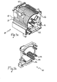
- Figures 2a, 2b, 3a, and 3b are perspective views of an embodiment of the two containment elements 40 and 50 provided by the invention.
- the first containment element 40 has a substantially prismatic shape, defined externally by a bottom resting surface 43 (not visible in the figures), a front surface 45, a first side wall 47 and a second side wall 48, a top surface 44 substantially opposite to the bottom surface 43, and, finally, a rear surface 49 substantially opposite to the front surface 45.
- the side surfaces as appears evident from Figures 2a and 3a, can be advantageously radiused in order to limit any sharp edges of the structure 1 and in order to meet the possible requirements linked to the operations of construction of the first containment component 40.
- the bottom surface 43 has an enlarged and reinforced surface so as to enable ease of resting and at the same time guarantee a greater solidity for the structure 1.
- the top surface 49 comprises a third opening, which enables insertion of the current-sensor means 3 in an internal cavity 38 made in the first element 40.
- the internal cavity 38 develops in a direction substantially orthogonal to the front surface 45 and has a configuration such as to enable containment of the toroidal core 10 in such a way that its axis will be substantially orthogonal to the front surface 45.
- the second containment element 50 has, instead, a prevalently flat configuration, basically comprising a front surface 51 and a rear surface 52 substantially opposed to the former.
- Figures 4a and 4b show the union of the two containment elements 40 and 50, according to a preferred embodiment of the invention.
- the rear surface 49 of the first containment element 40 is fitted to the front surface 51 of the second containment element 50.
- the second containment element 50 acts, in practice, as lid, enabling the toroidal core to be completely contained within the internal cavity 38 of the first containment element 40.
- the coupling means which enable union of the two containment elements 40 and 50 can be represented, for example by pins 61 and by geometrically conjugated seats 62 made, respectively, on the rear surface 49 of the first containment element 40 and/or on the front surface 51 of the second containment element 50.
- first and second openings 41 and 42 are made on the front surface 45 of the first element 40 and on the front surface 51 of the second containment element 50, whilst the second openings 42 are made on at least one of the side surfaces 47 and 48.
- the arrangement of the first openings 41 referred to above is such as to enable the primary conductors 12 of the primary winding to maintain a position substantially concentric to the toroidal core 10 so as to guarantee correct operation of the sensor means 3.
- the second openings 42 provide a useful and constant reference on the position of the terminals 17 of the secondary winding 15 on the outside of said containment elements 40 and 50 for the automatic machines used for assembly.
- the two containment elements 40 and 50 advantageously comprise also fourth openings that can be used to enable the terminals of a possible third winding 70 to come out, said third winding being used, for example, for providing a testing circuit dedicated to verification of operation of the electrical-protection apparatuses for which there is envisaged the use of sensor means 3.
- these fourth openings are preferably made through recesses 105 provided on the rear surface 49 of the first containment element 40.
- the containment structure 1 conveniently comprises also first means for housing these components, which may be obtained through shaped seats 77 made on the first element 40 and/or on the parts referred to above that jut out therefrom.
- the containment structure 1 advantageously comprises first means for guiding and mutual insulation of the primary conductors 12, which constitute the winding, within the containment elements 40 and 50.
- These first guide means have, in fact, the purpose of guaranteeing correct operation of the current-sensor means 3, for which the primary conductors 12 are required to be mutually insulated from one another in order to prevent any undesired interaction, as well as being appropriately guided and supported in the stretch of their length that traverses the toroidal core 10 on the inside.
- the above first guiding and mutual-insulation means comprise first internal ends 81, which project from the front surface 45 of the first containment element 40 and from the front surface 51 of the second containment element 50.
- the containment structure 1 comprises also second guiding and insulation means for the primary conductors 12, on the outside of the two containment elements 40 and 50.
- These second means can be made, for example, via shapings 82 projecting outwards from the front surface of the first containment element 40 and/or from the rear surface of the second containment element 50.
- This solution is particularly effective in so far as it enables prevention of any contact between the primary conductors 12 and enables the terminals 13 thereof to reach a well-defined and constant position by means of a simple operation of bending. In this way, said terminals 13 of the primary conductors 12 can be easily connected to the other parts of the protection apparatus in which the structure 1 is inserted.
- the containment structure 1 comprises supporting means and/or spacers designed to maintain the toroidal core 10 in the position assumed in the step of its insertion within the containment elements 40 and 50.
- Said latter supporting means enable prevention of any relative displacement of the toroidal core 10 with respect to the cavity 38 in which it is inserted, in the case where said core 10 has an axial thickness of dimensions considerably smaller than the depth of said cavity 38.
- the supporting means comprise second internal ends projecting from the front surface 51 of the second containment element 50. Said second ends (not visible in the figures) develop in a direction substantially orthogonal to said front surface 51 and rest their free ends on the toroidal core, thus preventing axial displacement thereof.
- the containment structure 1 comprises means for anchoring said structure, as well as further positioning means designed to simplify and optimize automatic conveyance.
- the anchoring means can be used, for example, in the assembly step, which envisages the bending of the primary conductors 12 that was referred to previously and will be described in greater detail hereinafter.
- said anchoring means comprise anchoring seats 90 made on the front surface 45 of the first containment element 40 and on the rear surface 52 of the second containment element 50.
- the positioning means referred to above again according to a preferred embodiment of the invention, comprise, instead, centring holes 96 made on the bottom resting surface 43 of the first containment element 40.
- FIG. 5 shows a containment structure 1, according to the invention, particularly suited for the construction of bipolar protection apparatuses
- Figure 6 regards, instead, a containment structure to be used in quadripolar protection apparatuses.
- both of the embodiments of the structure 1 comprise second means for housing interface elements 110, which can be advantageously used to provide a rigid outlet in a fixed position for the terminals 17 of the secondary winding 15, in order to enable ease of connection of said terminals 17 to the elements for actuation of the protection apparatus, such as, for example, a relay.
- These second housing means may preferably be made via a housing pocket 115, positioned outside the first containment element 40 and having a first part 116 projecting from the first containment element 40.
- Said housing pocket as may be noted also from Figure 4a, comprises first grooves 120 for insertion of the aforementioned interface elements 110 according to a direction substantially parallel to the one in which the first containment element 40 develops.
- Figure 6 indicates also the presence of a service pocket 130 designed, according to the invention, for housing said interface elements 110 during the step of assembly in which the terminals 17 of the secondary winding 15 are welded to said interface elements 110 and, at the same time, during which the terminals of the third winding 70 are welded to the testing circuit.
- said service pocket is made through a second part projecting from the first containment element 40 and has second grooves 140 for insertion of the interface elements 110 in a direction that enables the aforesaid welds to be made on substantially the same plane.
- a solution of this type leads to considerable advantages in so far as it enables all the connections to be made with just a single operation.
- both containment elements 40 and 50 may comprise also cantilever parts 99, which, as has already been mentioned above, may be used, for example, for housing the components forming the testing circuit. It should be emphasized how said cantilever parts 99 provide a further advantage in so far as they enable positioning of the containment structure 1 inside protection apparatuses of various sizes, in such a way that the interface elements can in any case maintain the same position with respect to the other parts of the apparatus, with evident advantages for the automation of the assembly line.
- the operations of assembly of the containment structure 1 according to the invention may be completely automated.
- the first operation in particular, consists in positioning the toroidal core 10 inside the cavity 38 present in the first containment element 40.
- the interface elements 110 and the components 81 of the circuit are positioned in the corresponding first and second housing means.
- the terminals 17 of the secondary winding 15 and the terminals 74 of the third winding, through the second openings 42 and the fourth openings 72, are welded, respectively, to the interface elements 110 and to the testing circuit, possibly using the service pocket 130 referred to above.
- the subsequent operations consist in fitting together the two containment elements 40 and 50 and in the subsequent insertion of the primary conductors 12 inside the elements themselves, by using the first guiding and mutual-insulation means.
- the containment structure 1 After anchoring the containment structure 1 using the corresponding anchoring means, there follows the operation of bending of said primary conductors 12, exploiting the action of the second guiding and mutual-insulation means. Finally, the containment structure is then inserted inside the box for containing electrical-protection apparatuses, possibly through the action of the centring holes used for automated conveyance to enable a more stable positioning.
- the containment structure is extremely simple and compact and is made up of a reduced number of components.
- the sensor means are stably contained inside the corresponding containment elements, and the structure itself can be stably inserted inside the electrical-protection device in which it is to be used.
Landscapes
- Engineering & Computer Science (AREA)
- Power Engineering (AREA)
- Transformers For Measuring Instruments (AREA)
- Measuring Instrument Details And Bridges, And Automatic Balancing Devices (AREA)
Abstract
Description
- The present invention relates to a structure for containing current-sensor means to be used in protection apparatuses for electrical networks, which may be, for example, bipolar or quadripolar circuit breakers or residual-current units appropriately coupled to a circuit-breaking unit.
- It is known that, in low-voltage electrical systems, apparatuses such as the ones mentioned above are widely used to interrupt the current flow in the electrical circuit in which they are employed when a residual current higher than a pre-set threshold value occurs. The purpose of such apparatuses is principally that of guaranteeing an adequate protection of the electrical system and of the loads applied thereto against the small dispersions that usually precede short-circuits. A further, and even more important, purpose is to protect persons from the so-called direct contacts, i.e., accidental contacts with a conductor carrying electric current, specifically with a phase of the circuit, which may be a stripped wire, a broken socket, etc., but also from indirect contacts, i.e., contacts with a conductive body that is normally insulated, such as the casing of an electrical household appliance, which, on account of a fault or failure or a random event, happens to come into contact with a phase of the circuit and is hence at a dangerous voltage.
- Almost all the devices currently employed for said purpose envisage the use of a residual-current sensor, which is constituted in its essential parts, illustrated in Figure 1, by a residual-current transformer having a
toroidal core 10, a primary winding, and asecondary winding 15. - The toroidal core is generally made of mild ferromagnetic material and is usually inserted inside appropriate protection and insulation covers 11. The primary winding is usually formed by
conductors 12, referred to as primary conductors, which are typically made of copper and are equal in number to the conductors of the circuit that carries the current to the various loads and appliances. The primary conductors are usually arranged so as to pass within the toroidal core and are electrically connected to the conductors of the electrical circuit. - The secondary winding is, instead, usually made of a conductor wound around the toroidal core, having its terminals operatively connected to the actuation means of the protection device, which are represented, for example, by a relay designed to actuate a kinematic chain which brings about opening of the electrical circuit and hence interruption of the current flow. These sensor means often comprise also a third winding 70 wound around the toroidal core and used for obtaining an electrical circuit designed to enable the testing of the device.
- At present, residual-current sensors of the above sort, albeit quite satisfactory from the standpoint of operation, present a number of drawbacks linked to industrialization and, in particular, to assembly of the sensors themselves with the other parts constituting the protection apparatus. Optimization of the assembly operations, as is known, represents a particularly important aspect of production since it has a considerable inpact on the final production costs. For this reason, the obvious tendency, also in this sector, is to mechanize and robotize the production lines to the maximum, reducing as much as possible the costs linked to human intervention.
- It is known that the use of automatic machines, such as robots, requires precise and fixed references to enable the correct and reliable repeatability of the operations and hence guarantee proper operation of the end product as well as a high standard of quality thereof.
- However, currently, during insertion of the sensor means in said protection apparatuses, said references become almost completely absent, frequently rendering manual intervention by operators still necessary to ensure proper execution of important operations, such as the welds necessary for connection of the terminals of the secondary winding to the terminals of the relay.
- Usually, in fact, the toroidal cores and the corresponding windings are simply positioned inside the apparatus, usually on the bottom of the containment box thereof, without there being defined, in this way, precise and constant references, for example, on the position of the terminals of the primary winding or of the terminals of the primary conductors. In such conditions, the use of an automatic machine becomes somewhat difficult if not, indeed, even useless.
- The situation is then further complicated in the presence of the aforesaid third winding, which also requires welds that guarantee its connection to the testing circuit. In particular, it should be emphasized how, at present, also positioning of other components of the testing circuit, for example, electrical resistors, frequently proves rather complicated, thus limiting possible automation of the assembly line.
- Another disadvantage of the current system for positioning the sensor means inside the protection apparatuses is linked to the possible movement of the toroidal core with respect to the rest of the apparatus, as a result of the absence of appropriate arrest means which prevent motion thereof. This situation can arise above all in the event of the apparatus itself being turned upside down once the assembly operation is concluded, or else during installation thereof on a vertical wall. Movements of this type are in any case to be avoided in so far as they can lead, for example, to damage of the connections referred to above made on the terminals of the windings.
- On the basis of the above considerations, the main task of the present invention is to provide a containment structure for current-sensor means to be used in the production of protection apparatuses for electrical networks which will enable to overcome the drawbacks mentioned above linked to the automation of the operations of assembly of said sensor means with the other components of the apparatus.
- In the context of the above task, the main purpose of the present invention is to provide a containment structure for current-sensor means which will provide precise references for execution of the connections of the terminals of the various windings used to the parts constituting the protection apparatus.
- A further purpose of the present invention is to provide a containment structure for current-sensor means formed by a small number of components that can be easily assembled together.
- Another purpose of the present invention is to provide a containment structure for current-sensor means which will enable a secure positioning of the sensor means within the apparatus in such a way as to prevent any relative movement between the parts.
- Not the least important purpose of the present invention is to provide a containment structure for current-sensor means that will present high reliability, relative ease of manufacture and competitive costs.
- The aforesaid tasks, as well as the above and other related purposes that will appear more clearly from what follows, are achieved by a containment structure for current-sensor means to be used for protection apparatuses for electrical networks. The sensor means comprise at least:
- a substantially toroidal core, enveloped by corresponding protection covers;
- a primary winding, comprising two or more primary conductors passing inside the toroidal core; and
- a secondary winding, wound on the outside of said protection covers of said toroidal core.
- The containment structure according to the invention is characterized in that it comprises at least a first containment element, coupled to a second containment element via corresponding coupling means. Said containment elements comprise inside them said sensor means and also comprise first openings and second openings for enabling terminals of said primary conductors and terminals of said secondary conductors, respectively, to come out.
- The possibility of stably containing the sensor means in a closed containment structure represents the main advantage of the invention so far as it enables precise and constant references to be obtained for positioning the structure itself inside the apparatus and for execution of the operations of welding of the terminals of the windings with the other parts forming the apparatus.
- Further characteristics and advantages of the invention will emerge more clearly from the description of preferred but non-exclusive embodiments of the containment structure according to the invention, illustrated by way of indicative and non-limiting example in the attached drawings, in which:
- Figure 1 is a perspective view representing current-sensor means according to an embodiment of a traditional type;
- Figures 2a and 2b provide a first perspective view of the two elements constituting a containment structure according to the invention prior to its assembly;
- Figures 3a and 3b provide a second perspective view of the two elements constituting a containment structure according to the invention prior to its assembly;
- Figures 4a and 4b provide perspective views of the union of the two elements constituting a containment structure according to the invention;
- Figure 5 is a perspective view of a containment structure according to the invention to be used for making a bipolar protection apparatus; and
- Figure 6 is a perspective view of a containment structure according to the invention to be used for making a quadripolar protection apparatus.
- With reference to the aforesaid figures, the
containment structure 1 according to the invention comprises, within it, current-sensor means 3 formed by atoroidal core 10, a primary winding, and asecondary winding 15. - The
toroidal core 10 is generally made of mild ferromagnetic material and is usually enveloped in appropriate protection covers 11, which ensure a perfect insulation thereof. The primary winding is formed by twoprimary conductors 12, which are preferably made of copper and are arranged so as to pass within thetoroidal core 10, as illustrated in Figure 1. Thesecondary winding 15 is wound, instead, on the outside of the protection covers 11 of thetoroidal core 10. - The
containment structure 1 is obtained with afirst containment element 40, which is coupled, via appropriate coupling means, to asecond containment element 50 in order to contain the aforesaid current-sensor means 3. Also provided in the twocontainment elements first openings 41 andsecond openings 42, which enable terminals of theprimary conductors 12 and terminals of thesecondary winding 15, respectively, to come out. - Figures 2a, 2b, 3a, and 3b are perspective views of an embodiment of the two
containment elements first containment element 40 has a substantially prismatic shape, defined externally by a bottom resting surface 43 (not visible in the figures), afront surface 45, afirst side wall 47 and asecond side wall 48, atop surface 44 substantially opposite to the bottom surface 43, and, finally, arear surface 49 substantially opposite to thefront surface 45. The side surfaces, as appears evident from Figures 2a and 3a, can be advantageously radiused in order to limit any sharp edges of thestructure 1 and in order to meet the possible requirements linked to the operations of construction of thefirst containment component 40. For constructional reasons similar to the ones just mentioned also the bottom surface 43 has an enlarged and reinforced surface so as to enable ease of resting and at the same time guarantee a greater solidity for thestructure 1. - With reference in particular to Figure 2a, the
top surface 49 comprises a third opening, which enables insertion of the current-sensor means 3 in aninternal cavity 38 made in thefirst element 40. Advantageously, theinternal cavity 38 develops in a direction substantially orthogonal to thefront surface 45 and has a configuration such as to enable containment of thetoroidal core 10 in such a way that its axis will be substantially orthogonal to thefront surface 45. - With reference to Figures 2b and 3b, the
second containment element 50 has, instead, a prevalently flat configuration, basically comprising afront surface 51 and arear surface 52 substantially opposed to the former. - Figures 4a and 4b show the union of the two
containment elements rear surface 49 of thefirst containment element 40 is fitted to thefront surface 51 of thesecond containment element 50. In this way, thesecond containment element 50 acts, in practice, as lid, enabling the toroidal core to be completely contained within theinternal cavity 38 of thefirst containment element 40. - With reference, instead, to Figures 2a and 3b, the coupling means which enable union of the two
containment elements pins 61 and by geometrically conjugatedseats 62 made, respectively, on therear surface 49 of thefirst containment element 40 and/or on thefront surface 51 of thesecond containment element 50. - From Figures 3a and 3b, it is also possible to note the arrangement of the first and
second openings first openings 41 are made on thefront surface 45 of thefirst element 40 and on thefront surface 51 of thesecond containment element 50, whilst thesecond openings 42 are made on at least one of theside surfaces - The arrangement of the
first openings 41 referred to above is such as to enable theprimary conductors 12 of the primary winding to maintain a position substantially concentric to thetoroidal core 10 so as to guarantee correct operation of the sensor means 3. In the same way, also thesecond openings 42 provide a useful and constant reference on the position of the terminals 17 of thesecondary winding 15 on the outside of saidcontainment elements - According to the invention, the two
containment elements recesses 105 provided on therear surface 49 of thefirst containment element 40. - In order to provide the aforementioned testing circuit, also other components are normally used, such as electrical resistors designed to simulate a voltage drop, which, in the case of correct operation of the protection circuit, is immediately detected by the sensor means 3. According to the invention, the
containment structure 1 conveniently comprises also first means for housing these components, which may be obtained through shapedseats 77 made on thefirst element 40 and/or on the parts referred to above that jut out therefrom. - With reference to Figures 3a and 3b, the
containment structure 1 advantageously comprises first means for guiding and mutual insulation of theprimary conductors 12, which constitute the winding, within thecontainment elements primary conductors 12 are required to be mutually insulated from one another in order to prevent any undesired interaction, as well as being appropriately guided and supported in the stretch of their length that traverses thetoroidal core 10 on the inside. - According to a preferred embodiment of the invention, the above first guiding and mutual-insulation means comprise first internal ends 81, which project from the
front surface 45 of thefirst containment element 40 and from thefront surface 51 of thesecond containment element 50. - With reference to Figure 3a, the
containment structure 1 according to the invention comprises also second guiding and insulation means for theprimary conductors 12, on the outside of the twocontainment elements shapings 82 projecting outwards from the front surface of thefirst containment element 40 and/or from the rear surface of thesecond containment element 50. This solution is particularly effective in so far as it enables prevention of any contact between theprimary conductors 12 and enables theterminals 13 thereof to reach a well-defined and constant position by means of a simple operation of bending. In this way, saidterminals 13 of theprimary conductors 12 can be easily connected to the other parts of the protection apparatus in which thestructure 1 is inserted. - Again with the purpose of ensuring correct operation of the current-sensor means 3, the
containment structure 1 according to the invention comprises supporting means and/or spacers designed to maintain thetoroidal core 10 in the position assumed in the step of its insertion within thecontainment elements toroidal core 10 with respect to thecavity 38 in which it is inserted, in the case where saidcore 10 has an axial thickness of dimensions considerably smaller than the depth of saidcavity 38. According to a preferred embodiment, the supporting means comprise second internal ends projecting from thefront surface 51 of thesecond containment element 50. Said second ends (not visible in the figures) develop in a direction substantially orthogonal to saidfront surface 51 and rest their free ends on the toroidal core, thus preventing axial displacement thereof. - In order to favour the assembly operations, the
containment structure 1 according to the invention comprises means for anchoring said structure, as well as further positioning means designed to simplify and optimize automatic conveyance. The anchoring means can be used, for example, in the assembly step, which envisages the bending of theprimary conductors 12 that was referred to previously and will be described in greater detail hereinafter. With reference to Figures 4a and 4b, according to a preferred embodiment of the invention, said anchoring means comprise anchoring seats 90 made on thefront surface 45 of thefirst containment element 40 and on therear surface 52 of thesecond containment element 50. - The positioning means referred to above, again according to a preferred embodiment of the invention, comprise, instead, centring
holes 96 made on the bottom resting surface 43 of thefirst containment element 40. - Figure 5 shows a
containment structure 1, according to the invention, particularly suited for the construction of bipolar protection apparatuses, whilst Figure 6 regards, instead, a containment structure to be used in quadripolar protection apparatuses. As may be noted, both of the embodiments of thestructure 1 comprise second means forhousing interface elements 110, which can be advantageously used to provide a rigid outlet in a fixed position for the terminals 17 of the secondary winding 15, in order to enable ease of connection of said terminals 17 to the elements for actuation of the protection apparatus, such as, for example, a relay. These second housing means may preferably be made via ahousing pocket 115, positioned outside thefirst containment element 40 and having afirst part 116 projecting from thefirst containment element 40. Said housing pocket, as may be noted also from Figure 4a, comprisesfirst grooves 120 for insertion of theaforementioned interface elements 110 according to a direction substantially parallel to the one in which thefirst containment element 40 develops. - Figure 6 indicates also the presence of a
service pocket 130 designed, according to the invention, for housing saidinterface elements 110 during the step of assembly in which the terminals 17 of the secondary winding 15 are welded to saidinterface elements 110 and, at the same time, during which the terminals of the third winding 70 are welded to the testing circuit. In particular, said service pocket is made through a second part projecting from thefirst containment element 40 and has second grooves 140 for insertion of theinterface elements 110 in a direction that enables the aforesaid welds to be made on substantially the same plane. A solution of this type leads to considerable advantages in so far as it enables all the connections to be made with just a single operation. - Again with reference to Figure 6, both
containment elements parts 99, which, as has already been mentioned above, may be used, for example, for housing the components forming the testing circuit. It should be emphasized how saidcantilever parts 99 provide a further advantage in so far as they enable positioning of thecontainment structure 1 inside protection apparatuses of various sizes, in such a way that the interface elements can in any case maintain the same position with respect to the other parts of the apparatus, with evident advantages for the automation of the assembly line. - The operations of assembly of the
containment structure 1 according to the invention may be completely automated. The first operation, in particular, consists in positioning thetoroidal core 10 inside thecavity 38 present in thefirst containment element 40. Subsequently, theinterface elements 110 and the components 81 of the circuit are positioned in the corresponding first and second housing means. The terminals 17 of the secondary winding 15 and the terminals 74 of the third winding, through thesecond openings 42 and the fourth openings 72, are welded, respectively, to theinterface elements 110 and to the testing circuit, possibly using theservice pocket 130 referred to above. The subsequent operations consist in fitting together the twocontainment elements primary conductors 12 inside the elements themselves, by using the first guiding and mutual-insulation means. After anchoring thecontainment structure 1 using the corresponding anchoring means, there follows the operation of bending of saidprimary conductors 12, exploiting the action of the second guiding and mutual-insulation means. Finally, the containment structure is then inserted inside the box for containing electrical-protection apparatuses, possibly through the action of the centring holes used for automated conveyance to enable a more stable positioning. - The technical solutions adopted for the containment structure enable the pre-set tasks and purposes to be fully achieved. In particular, the containment structure is extremely simple and compact and is made up of a reduced number of components. The sensor means are stably contained inside the corresponding containment elements, and the structure itself can be stably inserted inside the electrical-protection device in which it is to be used.
- Assembly of the containment structure is completely automated, as likewise are the operations of conveyance, of insertion of said structure in the protection apparatus, and of connection thereto, owing to the precise and constant references offered by the technical solutions adopted.
- The containment structure for current-sensor means thus conceived may undergo numerous modifications and variations, all falling within the scope of the inventive idea; in addition, all the details may be replaced by other technically equivalent elements. In practice, the materials used, as well as the dimensions and shapes, may be any whatsoever according to the requirements and the state of the art.
Claims (26)
- A containment structure (1) for containing current-sensor means to be used in protection apparatuses for electrical networks, said sensor means comprising at least:said containment structure being characterized in that it comprises at least a first containment element (40), coupled to a second containment element (50) via corresponding coupling means (60); said containment elements (40, 50) comprising inside them said sensor means and comprising first openings (41) and second openings (42) for enabling terminals (12) of said primary conductors (12) and terminals (17) of said secondary winding (15), respectively, to come out.a substantially toroidal core (10), enveloped by corresponding protection covers (11);a primary winding, comprising two or more primary conductors (12) passing inside the toroidal core (10); anda secondary winding (15), wound on the outside of said protection covers (11) of said toroidal core (10);
- The containment structure (1) according to Claim 1, characterized in that said toroidal core (10) is completely contained inside said first element (40).
- The containment structure (1) according to Claim 1 or Claim 2, characterized in that said first containment element (40) has a substantially prismatic shape with an internal cavity (38) designed to contain said sensor means, said first element (40) comprising externally a bottom resting surface (43), a front surface (45), a first side wall (47) and a second side wall (48), a top surface (44) opposite to said bottom surface (43), and a rear surface (49) opposite to said front surface (45), said rear surface (49) comprising a third opening for insertion of said sensor means within said internal cavity (38).
- The containment structure (1) according to Claim 3, characterized in that said internal cavity (38) develops in a direction substantially orthogonal to said front surface (45), said internal cavity (38) containing said toroidal core (10) in such a way that its axis will be substantially orthogonal to said front surface (45).
- The containment structure (1) according to one or more of the preceding claims, characterized in that said second containment element (50) has a prevalently flat configuration, comprising a front surface (51) and a rear surface (52) opposed to the former.
- The containment structure (1) according to one or more of the preceding claims, characterized in that said rear surface (49) of said first containment element (40) is coupled to said front surface (51) of said second containment element (50).
- The containment structure (1) according to Claim 6, characterized in that said coupling means (60) comprise pins (61) and geometrically conjugated seats (62) made, respectively, on said rear surface (46) of said first containment element (40) and/or on said front surface (51) of said second containment element (50).
- The containment structure (1) according to one or more of the preceding claims, characterized in that it comprises cantilever parts (99) projecting from said first containment element (40) and/or from said second containment element (50).
- The containment structure (1) according to Claim 1, characterized in that said first openings (41) are made on the front surface (45) of said first element (40) and on the front surface (51) of said second containment element (50), said second openings (42) being made on at least one of said side surfaces (47, 48) belonging to said first containment element (40).
- The containment structure (1) according to one or more of the preceding claims, characterized in that said containment elements (40, 50) comprise fourth openings for enabling the terminals (74) of a third winding (70) of said toroidal core (10) to come out, said third winding (70) being used for providing a testing circuit (71) for verifying correct operation of said protection apparatus.
- The containment structure (1) according to Claim 10, characterized in that said fourth openings are preferably made through recesses (105) made on said rear surface (46) of said first containment element (40).
- The containment structure (1) according to Claim 10 or Claim 11, characterized in that it comprises first means for housing the components used for providing said testing circuit (71).
- The containment structure (1) according to Claim 12, characterized in that said first housing means comprise said shaped seats (77) made on said first containment element (40) and/or on said cantilever parts (99) projecting from said first containment element (40).
- The containment structure (1) according to one or more of the preceding claims, characterized in that it comprises first means for guiding and mutual insulation of said primary conductors (12) within said containment elements (40, 50).
- The containment structure (1) according Claim to 14, characterized in that said first guiding and mutual-insulation means comprise first internal ends (81), which project from said front surface (45) of said first containment element (40) and from said front surface (51) of said second containment element (50), said first internal ends (81) developing in a direction substantially orthogonal to said front surface (45) and to said front surface (51).
- The containment structure (1) according to one or more of the preceding claims, characterized in that it comprises second guiding and mutual-insulation means for said conductors on the outside of said containment elements (40, 50).
- The containment structure (1) according to Claim 16, characterized in that said second guiding and mutual-insulation means are made via shapings (82) projecting outwards from the front surface (45) of said first containment element (40) and/or from said rear surface (52) of said second containment element (50).
- The containment structure (1) according to one or more of the preceding claims, characterized in that it comprises means for anchorage of said structure (1).
- The containment structure (1) according to Claim 18, characterized in that said anchoring means comprise anchoring seats (90) made on said front surface (45) of said first containment element (40) and on said rear surface (52) of said second containment element (50).
- The containment structure (1) according to one or more of the preceding claims, characterized in that it comprises supporting means and/or spacers for said toroidal core (10).
- The containment structure (1) according to Claim 20, characterized in that said supporting means and/or spacers comprise second internal ends projecting from said front surface (51) of said second element (50), said second internal ends developing in a direction substantially orthogonal to said front surface (51) and resting their free ends on said toroidal core (10).
- The containment structure (1) according to one or more of the preceding claims, characterized in that it comprises positioning means designed to simplify and optimize automated conveyance during the step of assembly of said protection apparatuses.
- The containment structure (1) according to Claim 22, characterized in that said positioning means comprise centring holes (96) made on said bottom resting surface (43) of said first containment element (40).
- The containment structure (1) according to Claim 1, characterized in that it comprises second means for housing interface elements (110) designed to provide a rigid outlet in a fixed position for said terminals (17) of said secondary winding (15).
- The containment structure (1) according to Claim 24, characterized in that said second housing means comprise at least one housing pocket (115), made on the outside of the first containment element (40), said housing pocket (115) being made through a first part (116) projecting from said first containment element (40) and having first grooves (120) for insertion of said interface elements (110) in a direction substantially parallel to that in which said first containment element (40) develops.
- The containment structure (1) according to one or more of the preceding claims, characterized in that it comprises a service pocket (130) designed for housing said interface elements (110) during the step of welding of said terminals (17) of said second winding (15) to said interface elements (110) and of said terminals of said third winding (74) to said testing circuit, said service pocket (130) being made through a second part projecting from said first containment element (40) and having second grooves (140) for insertion of said interface elements (110) in a direction that enables the aforesaid welds to be made on substantially the same plane.
Applications Claiming Priority (2)
| Application Number | Priority Date | Filing Date | Title |
|---|---|---|---|
| ITBG20030034 ITBG20030034A1 (en) | 2003-05-20 | 2003-05-20 | DEVICE FOR CONTAINING HALF CURRENT SENSORS. |
| ITBG20030034 | 2003-05-20 |
Publications (3)
| Publication Number | Publication Date |
|---|---|
| EP1480244A2 true EP1480244A2 (en) | 2004-11-24 |
| EP1480244A3 EP1480244A3 (en) | 2006-10-25 |
| EP1480244B1 EP1480244B1 (en) | 2015-04-22 |
Family
ID=33042671
Family Applications (1)
| Application Number | Title | Priority Date | Filing Date |
|---|---|---|---|
| EP20040076452 Expired - Lifetime EP1480244B1 (en) | 2003-05-20 | 2004-05-18 | A device for containing current-sensor means |
Country Status (2)
| Country | Link |
|---|---|
| EP (1) | EP1480244B1 (en) |
| IT (1) | ITBG20030034A1 (en) |
Cited By (3)
| Publication number | Priority date | Publication date | Assignee | Title |
|---|---|---|---|---|
| CN101707128B (en) * | 2009-11-08 | 2011-07-20 | 江阴市星火电子科技有限公司 | Magnetic circuit open-close type current transformer |
| CN112951573A (en) * | 2021-01-29 | 2021-06-11 | 杭州萧山玉峰电力科技有限公司 | Zero sequence mutual inductor |
| EP4718081A1 (en) * | 2024-09-30 | 2026-04-01 | Schneider Electric USA, Inc. | Enhanced differential sensor winding pattern |
Family Cites Families (6)
| Publication number | Priority date | Publication date | Assignee | Title |
|---|---|---|---|---|
| FR2532793A1 (en) * | 1982-09-08 | 1984-03-09 | Merlin Gerin | Short-circuit and differential hybrid trip unit equipped with a current transformer with common homopolar torus. |
| US4702002A (en) * | 1985-04-22 | 1987-10-27 | General Electric Company | Method of forming signal processor module for ground fault circuit breaker |
| FR2662014B1 (en) * | 1990-05-10 | 1992-07-24 | Merlin Gerin | HOMOPOLAR TRANSFORMER FOR DIFFERENTIAL SWITCHES OR CIRCUIT BREAKERS AND MOUNTING METHOD. |
| DE4111236C2 (en) * | 1991-04-08 | 1999-04-08 | Abb Patent Gmbh | Total current transformer for a residual current circuit breaker |
| FR2701335B1 (en) * | 1993-02-09 | 1995-04-14 | Merlin Gerin | Differential protection block with testable functional sub-assembly. |
| GB9414873D0 (en) * | 1994-07-23 | 1994-09-14 | Delta Circuits Protection | Current imbalance sensor |
-
2003
- 2003-05-20 IT ITBG20030034 patent/ITBG20030034A1/en unknown
-
2004
- 2004-05-18 EP EP20040076452 patent/EP1480244B1/en not_active Expired - Lifetime
Non-Patent Citations (1)
| Title |
|---|
| None |
Cited By (4)
| Publication number | Priority date | Publication date | Assignee | Title |
|---|---|---|---|---|
| CN101707128B (en) * | 2009-11-08 | 2011-07-20 | 江阴市星火电子科技有限公司 | Magnetic circuit open-close type current transformer |
| CN112951573A (en) * | 2021-01-29 | 2021-06-11 | 杭州萧山玉峰电力科技有限公司 | Zero sequence mutual inductor |
| CN112951573B (en) * | 2021-01-29 | 2022-08-19 | 杭州萧山玉峰电力科技有限公司 | Zero sequence mutual inductor |
| EP4718081A1 (en) * | 2024-09-30 | 2026-04-01 | Schneider Electric USA, Inc. | Enhanced differential sensor winding pattern |
Also Published As
| Publication number | Publication date |
|---|---|
| ITBG20030034A1 (en) | 2004-11-21 |
| EP1480244A3 (en) | 2006-10-25 |
| EP1480244B1 (en) | 2015-04-22 |
Similar Documents
| Publication | Publication Date | Title |
|---|---|---|
| KR100237808B1 (en) | Circuit breakers and manufacturing method thereof | |
| KR101015333B1 (en) | Circuit breaker | |
| US4702002A (en) | Method of forming signal processor module for ground fault circuit breaker | |
| JPH08512427A (en) | Ground fault module conductor and base therefor | |
| US20050275981A1 (en) | GFCI wiring device with integral relay module | |
| WO2005094499A2 (en) | Heat sensing electrical receptacle | |
| JPH09270225A5 (en) | ||
| WO2007044189A2 (en) | One-shot heat sensing electrical receptacle | |
| US20150068881A1 (en) | Two-pole circuit breaker with trip bar apparatus and methods | |
| EP1480244B1 (en) | A device for containing current-sensor means | |
| CN110022036B (en) | Thermal limiter fuse system for motor protection | |
| US7190246B2 (en) | Ground fault circuit interrupter | |
| KR102428329B1 (en) | Thermal protector | |
| JP2011100606A (en) | Earth leakage breaker | |
| EP1050059A1 (en) | Instantaneous trip power transformer | |
| USRE31017E (en) | Method for fusing male plug at end of power line cord | |
| EP1480243B1 (en) | An electrical device for protection against residual currents | |
| KR101252409B1 (en) | Base assembly having a heater combination portion and circuit breaker for electric wiring having the same | |
| JP6770759B1 (en) | Wire connection equipment | |
| JP5250789B2 (en) | 2-pole circuit breaker | |
| JP4967453B2 (en) | Earth leakage breaker | |
| JP4994820B2 (en) | Circuit breaker | |
| KR100527032B1 (en) | Receptacle | |
| JP4885596B2 (en) | 2-pole circuit breaker | |
| JP2024061946A (en) | Earth leakage breaker |
Legal Events
| Date | Code | Title | Description |
|---|---|---|---|
| PUAI | Public reference made under article 153(3) epc to a published international application that has entered the european phase |
Free format text: ORIGINAL CODE: 0009012 |
|
| AK | Designated contracting states |
Kind code of ref document: A2 Designated state(s): AT BE BG CH CY CZ DE DK EE ES FI FR GB GR HU IE IT LI LU MC NL PL PT RO SE SI SK TR |
|
| AX | Request for extension of the european patent |
Extension state: AL HR LT LV MK |
|
| PUAL | Search report despatched |
Free format text: ORIGINAL CODE: 0009013 |
|
| AK | Designated contracting states |
Kind code of ref document: A3 Designated state(s): AT BE BG CH CY CZ DE DK EE ES FI FR GB GR HU IE IT LI LU MC NL PL PT RO SE SI SK TR |
|
| AX | Request for extension of the european patent |
Extension state: AL HR LT LV MK |
|
| 17P | Request for examination filed |
Effective date: 20070116 |
|
| AKX | Designation fees paid |
Designated state(s): AT BE BG CH CY CZ DE DK EE ES FI FR GB GR HU IE IT LI LU MC NL PL PT RO SE SI SK TR |
|
| RAP1 | Party data changed (applicant data changed or rights of an application transferred) |
Owner name: ABB S.P.A. |
|
| 17Q | First examination report despatched |
Effective date: 20110222 |
|
| REG | Reference to a national code |
Ref country code: DE Ref legal event code: R079 Ref document number: 602004047041 Country of ref document: DE Free format text: PREVIOUS MAIN CLASS: H01H0083140000 Ipc: H01F0027300000 |
|
| GRAP | Despatch of communication of intention to grant a patent |
Free format text: ORIGINAL CODE: EPIDOSNIGR1 |
|
| RIC1 | Information provided on ipc code assigned before grant |
Ipc: H01F 38/30 20060101ALI20141030BHEP Ipc: H01H 83/04 20060101ALN20141030BHEP Ipc: H01F 27/30 20060101AFI20141030BHEP Ipc: H01H 83/14 20060101ALI20141030BHEP |
|
| RIC1 | Information provided on ipc code assigned before grant |
Ipc: H01F 27/30 20060101AFI20141106BHEP Ipc: H01H 83/04 20060101ALN20141106BHEP Ipc: H01F 38/30 20060101ALI20141106BHEP Ipc: H01H 83/14 20060101ALI20141106BHEP |
|
| INTG | Intention to grant announced |
Effective date: 20141120 |
|
| GRAS | Grant fee paid |
Free format text: ORIGINAL CODE: EPIDOSNIGR3 |
|
| GRAA | (expected) grant |
Free format text: ORIGINAL CODE: 0009210 |
|
| AK | Designated contracting states |
Kind code of ref document: B1 Designated state(s): AT BE BG CH CY CZ DE DK EE ES FI FR GB GR HU IE IT LI LU MC NL PL PT RO SE SI SK TR |
|
| REG | Reference to a national code |
Ref country code: GB Ref legal event code: FG4D |
|
| REG | Reference to a national code |
Ref country code: CH Ref legal event code: EP |
|
| REG | Reference to a national code |
Ref country code: AT Ref legal event code: REF Ref document number: 723669 Country of ref document: AT Kind code of ref document: T Effective date: 20150515 |
|
| REG | Reference to a national code |
Ref country code: IE Ref legal event code: FG4D |
|
| REG | Reference to a national code |
Ref country code: DE Ref legal event code: R096 Ref document number: 602004047041 Country of ref document: DE Effective date: 20150603 |
|
| REG | Reference to a national code |
Ref country code: NL Ref legal event code: VDEP Effective date: 20150422 |
|
| REG | Reference to a national code |
Ref country code: AT Ref legal event code: MK05 Ref document number: 723669 Country of ref document: AT Kind code of ref document: T Effective date: 20150422 |
|
| PG25 | Lapsed in a contracting state [announced via postgrant information from national office to epo] |
Ref country code: NL Free format text: LAPSE BECAUSE OF FAILURE TO SUBMIT A TRANSLATION OF THE DESCRIPTION OR TO PAY THE FEE WITHIN THE PRESCRIBED TIME-LIMIT Effective date: 20150422 |
|
| PG25 | Lapsed in a contracting state [announced via postgrant information from national office to epo] |
Ref country code: FI Free format text: LAPSE BECAUSE OF FAILURE TO SUBMIT A TRANSLATION OF THE DESCRIPTION OR TO PAY THE FEE WITHIN THE PRESCRIBED TIME-LIMIT Effective date: 20150422 Ref country code: PT Free format text: LAPSE BECAUSE OF FAILURE TO SUBMIT A TRANSLATION OF THE DESCRIPTION OR TO PAY THE FEE WITHIN THE PRESCRIBED TIME-LIMIT Effective date: 20150824 Ref country code: ES Free format text: LAPSE BECAUSE OF FAILURE TO SUBMIT A TRANSLATION OF THE DESCRIPTION OR TO PAY THE FEE WITHIN THE PRESCRIBED TIME-LIMIT Effective date: 20150422 |
|
| PG25 | Lapsed in a contracting state [announced via postgrant information from national office to epo] |
Ref country code: AT Free format text: LAPSE BECAUSE OF FAILURE TO SUBMIT A TRANSLATION OF THE DESCRIPTION OR TO PAY THE FEE WITHIN THE PRESCRIBED TIME-LIMIT Effective date: 20150422 Ref country code: GR Free format text: LAPSE BECAUSE OF FAILURE TO SUBMIT A TRANSLATION OF THE DESCRIPTION OR TO PAY THE FEE WITHIN THE PRESCRIBED TIME-LIMIT Effective date: 20150723 |
|
| REG | Reference to a national code |
Ref country code: CH Ref legal event code: PL |
|
| REG | Reference to a national code |
Ref country code: DE Ref legal event code: R097 Ref document number: 602004047041 Country of ref document: DE |
|
| PG25 | Lapsed in a contracting state [announced via postgrant information from national office to epo] |
Ref country code: CH Free format text: LAPSE BECAUSE OF NON-PAYMENT OF DUE FEES Effective date: 20150531 Ref country code: EE Free format text: LAPSE BECAUSE OF FAILURE TO SUBMIT A TRANSLATION OF THE DESCRIPTION OR TO PAY THE FEE WITHIN THE PRESCRIBED TIME-LIMIT Effective date: 20150422 Ref country code: LI Free format text: LAPSE BECAUSE OF NON-PAYMENT OF DUE FEES Effective date: 20150531 Ref country code: MC Free format text: LAPSE BECAUSE OF FAILURE TO SUBMIT A TRANSLATION OF THE DESCRIPTION OR TO PAY THE FEE WITHIN THE PRESCRIBED TIME-LIMIT Effective date: 20150422 Ref country code: DK Free format text: LAPSE BECAUSE OF FAILURE TO SUBMIT A TRANSLATION OF THE DESCRIPTION OR TO PAY THE FEE WITHIN THE PRESCRIBED TIME-LIMIT Effective date: 20150422 Ref country code: IT Free format text: LAPSE BECAUSE OF FAILURE TO SUBMIT A TRANSLATION OF THE DESCRIPTION OR TO PAY THE FEE WITHIN THE PRESCRIBED TIME-LIMIT Effective date: 20150422 |
|
| REG | Reference to a national code |
Ref country code: IE Ref legal event code: MM4A |
|
| PLBE | No opposition filed within time limit |
Free format text: ORIGINAL CODE: 0009261 |
|
| STAA | Information on the status of an ep patent application or granted ep patent |
Free format text: STATUS: NO OPPOSITION FILED WITHIN TIME LIMIT |
|
| PG25 | Lapsed in a contracting state [announced via postgrant information from national office to epo] |
Ref country code: CZ Free format text: LAPSE BECAUSE OF FAILURE TO SUBMIT A TRANSLATION OF THE DESCRIPTION OR TO PAY THE FEE WITHIN THE PRESCRIBED TIME-LIMIT Effective date: 20150422 Ref country code: PL Free format text: LAPSE BECAUSE OF FAILURE TO SUBMIT A TRANSLATION OF THE DESCRIPTION OR TO PAY THE FEE WITHIN THE PRESCRIBED TIME-LIMIT Effective date: 20150422 Ref country code: SK Free format text: LAPSE BECAUSE OF FAILURE TO SUBMIT A TRANSLATION OF THE DESCRIPTION OR TO PAY THE FEE WITHIN THE PRESCRIBED TIME-LIMIT Effective date: 20150422 Ref country code: RO Free format text: LAPSE BECAUSE OF NON-PAYMENT OF DUE FEES Effective date: 20150422 |
|
| GBPC | Gb: european patent ceased through non-payment of renewal fee |
Effective date: 20150722 |
|
| 26N | No opposition filed |
Effective date: 20160125 |
|
| PG25 | Lapsed in a contracting state [announced via postgrant information from national office to epo] |
Ref country code: IE Free format text: LAPSE BECAUSE OF NON-PAYMENT OF DUE FEES Effective date: 20150518 Ref country code: GB Free format text: LAPSE BECAUSE OF NON-PAYMENT OF DUE FEES Effective date: 20150722 |
|
| REG | Reference to a national code |
Ref country code: FR Ref legal event code: PLFP Year of fee payment: 13 |
|
| PG25 | Lapsed in a contracting state [announced via postgrant information from national office to epo] |
Ref country code: SI Free format text: LAPSE BECAUSE OF FAILURE TO SUBMIT A TRANSLATION OF THE DESCRIPTION OR TO PAY THE FEE WITHIN THE PRESCRIBED TIME-LIMIT Effective date: 20150422 |
|
| PG25 | Lapsed in a contracting state [announced via postgrant information from national office to epo] |
Ref country code: BE Free format text: LAPSE BECAUSE OF FAILURE TO SUBMIT A TRANSLATION OF THE DESCRIPTION OR TO PAY THE FEE WITHIN THE PRESCRIBED TIME-LIMIT Effective date: 20150422 |
|
| REG | Reference to a national code |
Ref country code: FR Ref legal event code: PLFP Year of fee payment: 14 |
|
| PG25 | Lapsed in a contracting state [announced via postgrant information from national office to epo] |
Ref country code: BG Free format text: LAPSE BECAUSE OF FAILURE TO SUBMIT A TRANSLATION OF THE DESCRIPTION OR TO PAY THE FEE WITHIN THE PRESCRIBED TIME-LIMIT Effective date: 20150422 Ref country code: HU Free format text: LAPSE BECAUSE OF FAILURE TO SUBMIT A TRANSLATION OF THE DESCRIPTION OR TO PAY THE FEE WITHIN THE PRESCRIBED TIME-LIMIT; INVALID AB INITIO Effective date: 20040518 |
|
| PG25 | Lapsed in a contracting state [announced via postgrant information from national office to epo] |
Ref country code: SE Free format text: LAPSE BECAUSE OF FAILURE TO SUBMIT A TRANSLATION OF THE DESCRIPTION OR TO PAY THE FEE WITHIN THE PRESCRIBED TIME-LIMIT Effective date: 20150422 Ref country code: CY Free format text: LAPSE BECAUSE OF FAILURE TO SUBMIT A TRANSLATION OF THE DESCRIPTION OR TO PAY THE FEE WITHIN THE PRESCRIBED TIME-LIMIT Effective date: 20150422 |
|
| PG25 | Lapsed in a contracting state [announced via postgrant information from national office to epo] |
Ref country code: TR Free format text: LAPSE BECAUSE OF FAILURE TO SUBMIT A TRANSLATION OF THE DESCRIPTION OR TO PAY THE FEE WITHIN THE PRESCRIBED TIME-LIMIT Effective date: 20150422 |
|
| PG25 | Lapsed in a contracting state [announced via postgrant information from national office to epo] |
Ref country code: LU Free format text: LAPSE BECAUSE OF NON-PAYMENT OF DUE FEES Effective date: 20150518 |
|
| REG | Reference to a national code |
Ref country code: FR Ref legal event code: PLFP Year of fee payment: 15 |
|
| REG | Reference to a national code |
Ref country code: DE Ref legal event code: R082 Ref document number: 602004047041 Country of ref document: DE Representative=s name: WUESTHOFF & WUESTHOFF, PATENTANWAELTE PARTG MB, DE Ref country code: DE Ref legal event code: R081 Ref document number: 602004047041 Country of ref document: DE Owner name: ABB SCHWEIZ AG, CH Free format text: FORMER OWNER: ABB S.P.A., MILANO, IT |
|
| PGFP | Annual fee paid to national office [announced via postgrant information from national office to epo] |
Ref country code: FR Payment date: 20230525 Year of fee payment: 20 Ref country code: DE Payment date: 20230519 Year of fee payment: 20 |
|
| REG | Reference to a national code |
Ref country code: DE Ref legal event code: R071 Ref document number: 602004047041 Country of ref document: DE |