EP1480237A2 - Separator for electric double-layer capacitor, electric double-layer capacitor, and manufacturing method of separator for electric double-layer capacitor - Google Patents
Separator for electric double-layer capacitor, electric double-layer capacitor, and manufacturing method of separator for electric double-layer capacitor Download PDFInfo
- Publication number
- EP1480237A2 EP1480237A2 EP04012094A EP04012094A EP1480237A2 EP 1480237 A2 EP1480237 A2 EP 1480237A2 EP 04012094 A EP04012094 A EP 04012094A EP 04012094 A EP04012094 A EP 04012094A EP 1480237 A2 EP1480237 A2 EP 1480237A2
- Authority
- EP
- European Patent Office
- Prior art keywords
- separator
- electric double
- layer capacitor
- fiber
- less
- Prior art date
- Legal status (The legal status is an assumption and is not a legal conclusion. Google has not performed a legal analysis and makes no representation as to the accuracy of the status listed.)
- Withdrawn
Links
Images




Classifications
-
- H—ELECTRICITY
- H01—ELECTRIC ELEMENTS
- H01G—CAPACITORS; CAPACITORS, RECTIFIERS, DETECTORS, SWITCHING DEVICES, LIGHT-SENSITIVE OR TEMPERATURE-SENSITIVE DEVICES OF THE ELECTROLYTIC TYPE
- H01G9/00—Electrolytic capacitors, rectifiers, detectors, switching devices, light-sensitive or temperature-sensitive devices; Processes of their manufacture
- H01G9/004—Details
- H01G9/02—Diaphragms; Separators
-
- Y—GENERAL TAGGING OF NEW TECHNOLOGICAL DEVELOPMENTS; GENERAL TAGGING OF CROSS-SECTIONAL TECHNOLOGIES SPANNING OVER SEVERAL SECTIONS OF THE IPC; TECHNICAL SUBJECTS COVERED BY FORMER USPC CROSS-REFERENCE ART COLLECTIONS [XRACs] AND DIGESTS
- Y02—TECHNOLOGIES OR APPLICATIONS FOR MITIGATION OR ADAPTATION AGAINST CLIMATE CHANGE
- Y02E—REDUCTION OF GREENHOUSE GAS [GHG] EMISSIONS, RELATED TO ENERGY GENERATION, TRANSMISSION OR DISTRIBUTION
- Y02E60/00—Enabling technologies; Technologies with a potential or indirect contribution to GHG emissions mitigation
- Y02E60/13—Energy storage using capacitors
Definitions
- the present invention relates to a separator for an electric double-layer capacitor, the electric double-layer capacitor, and a manufacturing method of the separator for the electric double-layer capacitor.
- An electric double-layer capacitor is also called an electric double-layer condenser, has a large capacity of a farad level, is superior in a cyclic property of a charging/discharging, and can be rapidly charged, so it is used for usages such as a backup power source of electronic appliances and a vehicle mount battery (energy buffer).
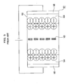
- FIG. 5 is a section view showing a basic configuration of the electric double-layer capacitor.
- An electric double-layer capacitor 101 has, as shown in FIG. 5, a configuration where a container 102, a pair of polarizable electrodes 104 disposed with opposing separators 103 for the electric double-layer capacitor within the container 102 (hereinafter abbreviated to the 'separator' as needed), and a pair of current collectors 105 are housed. And within the container 102 an ion conductive electrolytic solution is injected.
- the electric double-layer capacitor 101 is a so-called secondary battery that repeats the charging/discharging with making charges (shown in symbols of + and - in FIG. 5), which are generated at an interface between the polarizable electrodes 104 and the electrolytic solution, a dielectric by an absorption/desorption of electrolytic solution ions to the polarizable electrodes 104 that are solid.
- separators 103 are necessary such an insulation property so as not to generate an electric leak between the polarizable electrodes 104 disposed at both sides of the separators 103, a high wetability for the electrolytic solution so that ions injected in the electrolytic solution can freely move, and thinness so as to be able to be housed more, for example, in a winding electric double-layer capacitor and the like.
- the separator for the electric double-layer capacitor are used mixed paper obtained by mixing the fibers such as olefin resins (for example, polyethylene, polypropylene, and the like), a cellulose, a polyester, and an aramid, and making paper from them (for example, see pages 3 to 5 in Japanese Patent Laid-Open Publication Hei 9-31883, pages 4 and 5 in Japanese Patent Laid-Open Publication 2001-244150, and pages 3 to 5 in Japanese Patent Laid-Open Publication 2001-185455).
- the fibers such as olefin resins (for example, polyethylene, polypropylene, and the like), a cellulose, a polyester, and an aramid, and making paper from them (for example, see pages 3 to 5 in Japanese Patent Laid-Open Publication Hei 9-31883, pages 4 and 5 in Japanese Patent Laid-Open Publication 2001-244150, and pages 3 to 5 in Japanese Patent Laid-Open Publication 2001-185455).
- an organic solvent such as propylene carbonate which is high in withstand voltage, is used as a solvent of an electrolyte in order to make the electric double-layer capacitor a large capacity.
- the electrolytic solution is injected after moisture, which is low in withstand voltage and easy to be electrolyzed, is completely removed, and electrodes, separators, and the like are sufficiently dried.
- the separator used for the electric double-layer capacitor is desirable to have a sufficient heat resistance for enduring a drying process, and generally, the separator formed of an aramid fiber and polyester fiber having the heat resistance is widely produced and used.
- the aramid fiber, the polyester fiber (for example, polyethylene terephthalate), and the like is an aromatic synthetic fiber containing a benzene ring. Accordingly, there is a problem that due to an influence of hydrophoby which the aromatic synthetic fiber has, the separator becomes low in wetability for the electrolytic solution where such the propylene carbonate, which is strong in hydrophily, is made a solvent.
- a separator for an electric double-layer capacitor that is high in wetability for the electrolytic solution and has the heat resistance and flexibility, the electric double-layer capacitor comprising the separator, and furthermore, a manufacturing method of the separator for the electric double-layer capacitor that is good in workability and excellent in productivity.
- a first aspect of the present invention is a separator for an electric double-layer capacitor that comprises a glass fiber, a polyester fiber, and an aramid fiber.
- the separator for the electric double-layer capacitor it comprises the glass fiber and thereby has a hydrophilic group (for example, a siranol (Si-OH)) such as a hydroxyl group (-OH) in the separator, a preferable wetability for an electrolyte solvent such as propylene carbonate, which is strong in hydrophily, can be realized.
- a hydrophilic group for example, a siranol (Si-OH)
- a hydroxyl group (-OH) in the separator a preferable wetability for an electrolyte solvent such as propylene carbonate, which is strong in hydrophily, can be realized.
- a second aspect of the present invention is, in the separator for the electric double-layer capacitor described in the first aspect of the invention, a separator for the electric double-layer capacitor that contains the glass fiber of not less than 10 mass percent and not more than 40 mass percent.
- the separator for the electric double-layer capacitor contains the grass fiber of not less than 10 mass percent and not more than 40 mass percent, a preferable wetability for the electrolyte solvent such as the propylene carbonate, which is strong in hydrophily, can be realized.
- a third aspect of the present invention is, in the separator for the electric double-layer capacitor described in any of the first and second aspects of the invention, a separator for the electric double-layer capacitor that contains the aramid fiber of not less than 40 mass percent and not more than 60 mass percent.
- the separator for the electric double-layer capacitor contains the aramid fiber of not less than 40 mass percent and not more than 60 mass percent and thereby has a preferable insulation property, an electric leak between electrodes disposed at both sides of separators can be prevented.
- a fourth aspect of the present invention is, in the separator for the electric double-layer capacitor described in any of the first to third aspects of the invention, a separator for the electric double-layer capacitor that contains the polyester fiber of not less than 10 mass percent and not more than 30 mass percent.
- the separator for the electric double-layer capacitor it contains the polyester fiber of not less than 10 mass percent and not more than 30 mass percent, a preferable retractility can be kept and a good workability can be realized.
- a fifth aspect of the present invention is, in the separator for the electric double-layer capacitor described in any of the first to fourth aspects of the invention, a separator for the electric double-layer capacitor that comprises an acryl resin and a cation fixing reinforcement agent as binders for binding the glass fiber, the aramid fiber, and the polyester fiber, and is made into paper.
- the separator for the electric double-layer capacitor it has the binders for binding and bonding the glass fiber, the aramid fiber, and the polyester fiber, they can be preferably bonded each other.
- a sixth aspect of the present invention is, in the separator for the electric double-layer capacitor described in any of the first to fifth aspects of the invention, a separator for the electric double-layer capacitor whose "tsubo ryou" is not less than 10 g/m 2 and not more than 30 g/m 2 , and thickness is not less than 20 ⁇ m and not more than 60 ⁇ m.
- the "tsubo ryou” is also called a coating amount or a surface density, and means mass per area of the separator.
- the “tsubo ryou” is referred to as the surface density.
- the separator for the electric double-layer capacitor the surface density is not less than 10 g/m 2 and not more than 30 g/m 2 , the separator can be made a preferable thickness of not less than 20 ⁇ m and not more than 60 ⁇ m.
- a seventh aspect of the present invention is a separator for the electric double-layer capacitor that comprises a fiber and an inorganic compound for forming hydrosol that adheres to a surface of the fiber.
- the inorganic compound for forming the hydrosol means that the inorganic compound can form sol with making water a dispersant. And the inorganic compound contributes to improve flexibility and retractility of the separator, thereby improving a workability and productivity thereof.
- the inorganic compound for forming the hydrosol is not limited to whether or not having formed the hydrosol in a state that the inorganic compound is contained in the separator.
- the "hydrosol” makes a solid (inorganic compound) dispersion particles with making water the dispersant, that is, the "hydrosol” is a colloid (also called a colloid solution).
- inorganic compounds for forming such the hydrosol are cited a silica (SiO 2 ), an alumina (Al 2 O 3 ), and the like.
- the separator for the electric double-layer capacitor is preferable to comprise at least one kind out of the silica and the alumina.
- the "fiber” is not specifically limited to its kind if applicable to the separator for the electric double-layer capacitor.
- the aramid fiber, and the polyester fiber as other fibers are cited, for example, a cellulose, a fluorine fiber, a PPS (PolyPhenylene Sulfide) fiber, and the like.
- the separator for the electric double-layer capacitor it comprises the inorganic compound for forming the hydrosol, a preferable wetability for the electrolyte solvent such as propylene carbonate, which is strong in hydrophily, can be realized.
- the inorganic compound is preferable to adhere to surfaces of the fibers, and furthermore, adhere thereto at an appropriate distance.
- the flexibility and the retractility as the separator for the electric double-layer capacitor do not be lost, thereby the separator being able to be easily wound.
- the wetability for an electrolytic solution can be more heightened and a performance such as a liquid hold ratio can be improved.
- An eighth aspect of the present invention is the separator for the electric double-layer capacitor described in the seventh aspect of the invention which separator contains the inorganic compound of not less than 1 mass percent and not more than 20 mass percent.
- the separator for the electric double-layer capacitor Because in accordance with such the separator for the electric double-layer capacitor the inorganic compound adheres to almost all areas of fiber surfaces of the separator at the appropriate distance, a surface area of the inorganic compound becomes large. Accordingly, the electrolyte solvent such as the propylene carbonate, which is strong in hydrophily, is held by the inorganic compound whose surface area and hydrophily are large and excellent, respectively. Thus the separator for the electric double-layer capacitor can bring out a preferable wetability.
- a ninth aspect of the present invention is a separator for the electric double-layer capacitor described in any of the seventh and eighth aspects of the invention, wherein the inorganic compound comprises a particulate inorganic compound and a particle diameter thereof is not less than 1 nm and not more than 500 nm.
- the separator for the electric double-layer capacitor Because in accordance with such the separator for the electric double-layer capacitor the particulate inorganic compound, whose particle diameter is not less than 1 nm and not more than 500 nm, adheres to fiber surfaces, total surface area of the inorganic compound and the fiber surfaces is remarkably increased. Accordingly, the separator for the electric double layer capacitor can be made a preferable wetability for the electrolyte solvent such as the propylene carbonate that is strong in hydrophily.
- a tenth aspect of the present invention is a separator for the electric double-layer capacitor described in any of the seventh and ninth aspects of the invention, wherein the fiber comprises at least the glass fiber, and total of the inorganic compound and the glass fiber is not less than 10 mass percent and not more than 50 mass percent.
- An eleventh aspect of the present invention is an electric double-layer capacitor that comprises any of the separators for the electric double-layer capacitor described in any of the first and tenth aspects of the invention,
- the electric double-layer capacitor it comprises the separator that has a preferable wetability for the electrolyte solvent, ion movements between polarizable electrodes become to be actively and minutely performed, thereby a charging/discharging can be preferably repeated.
- a twelfth aspect of the present invention is a manufacturing method of a separator for the electric double-layer capacitor which method comprises a mixing process for mixing a fiber and an inorganic compound that is dispersed with forming hydrosol; and a paper making process for making paper from the mixed fiber and inorganic compound.
- the fiber and the inorganic compound are uniformly mixed by mixing them by an appropriate means. Then by making paper from the fiber and the inorganic compound, the separator for the electric double-layer capacitor, where the inorganic compound is uniformly dispersed in the fiber and adheres thereto, can be made.
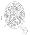
- FIGS. 1 to 3 As needed.
- the present invention is not limited to the embodiments below.
- a separator 1 for an electric double-layer capacitor (hereinafter abbreviated to the "separator") is configured of aramid fibers 2, polyester fibers 3, and glass fibers 4 are bonded each other by binders (not shown); and furthermore, silicas 5 (an inorganic compound for forming hydrosol) adhere to a surface of each fiber in a dispersion state by the binders. Then the silicas 5 are formed with comprising minute particles of particulate silicas 6 (inorganic compound) and are a generic name of a silica that consists of single particulate silica 6 and adheres to the surface of each fiber; and another silica where the particulate silicas 6 are congregated and adhere to each fiber. Meanwhile, the silicas 5 may not be comprised in some case.
- the aramid fibers 2 are also called an aromatic polyamide, are a polymer where aromatic groups bond in an amide bond, and are a material having a water repellency and an insulation property.
- the insulation property is preferably improved by the aramid fibers 2 being comprised in the separator 1, and an. electric leak between electrodes disposed with opposing to the separator 1 is difficult to occur.
- the aramid fibers 2 are preferably a fiber that is fibrillated.
- the aramid fibers 2 is preferably contained in the separator 1 by not less than 40 mass percent and not more than 60 mass percent. If a containment amount of the aramid fibers 2 is less than 40 mass percent, a maximum pore size formed in the separator 1 tends to become larger, thereby the insulation property resulting in lowering. On the other hand, if the containment amount of the aramid fibers 2 is more than 60 mass percent, a void content of the separator 1 decreases, thereby an ion permeation amount in an electrolytic solution also decreasing and an internal resistance of the separator 1 becoming high.
- the internal resistance is a resistance which ions in the electrolytic solution receive when moving within the separator 1.
- the void content is something for showing a porosity of a fiber occupying an apparent volume of the separator 1, and is calculated from a specific gravity of the fibers configuring the separator 1 and a density of the separator 1.
- the aramid fibers 2 can be selected/used from conventionally known ones as needed, taking the conditions described above into consideration: for example, are cited Cornex (R) of a meta-aramid fiber (manufactured by Teijin Ltd.), Kevlar (R) of a para-aramid fiber (manufactured by DuPont), Towaron (R) (manufactured by Teijin Towaron B.V.), and the like.
- the polyester fibers 3 are a synthetic fiber represented by a polyethylene terephthalate (PET fiber) that is synthesized from a terephthalic acid and an ethylene glycol, and are a material having the retractility and the insulation property.
- PET fiber polyethylene terephthalate
- the polyester fibers 3 are preferably ones containing aromatic rings because they are excellent in heat resistance.
- the retractility of the separator 1 can be preferably improved. For example, because in manufacturing a winding capacitor the capacitor can be wound with giving more loads, the separator 1 results in being able to be easily deformed, depending on a shape of a container and a swelling of a polarizable electrode in containing the electrolytic solution.
- polyester fibers 3 are preferably not more than 0.33 dtex in denier. If the denier becomes more than 0.33 dtex, a pore diameter formed in the separator 1 becomes large, thereby the insulation property tending to deteriorate.
- the polyester fibers 3 is preferable to be contained in the separator 1 by not less than 10 mass percent and not more than 30 mass percent. If a containment amount of the polyester fibers 3 is less than 10 mass percent, even the glass fibers 4 contained in the separator 1 together with the polyester fibers 3 are decreased, the separator 1 tends to become difficult to elongate. On the other hand, if the containment amount of the polyester fibers 3 is more than 30 mass percent, the pore diameter formed in the separator 1 becomes large, thereby the insulation property tending to deteriorate.
- the polyester fibers 3 can be selected/used from conventionally known ones as needed, taking the conditions described above into consideration: for example, are cited Vectran (R) (manufactured by Kuraray Co., Ltd), Tepyrus (R) (manufactured by Teijin Ltd.), Unitika Ester (manufactured by Unitika Fiber Ltd.), Kuraray Polyester (manufactured by Kuraray Co., Ltd), and the like.
- Vectran (R) manufactured by Kuraray Co., Ltd
- Tepyrus (R) manufactured by Teijin Ltd.
- Unitika Ester manufactured by Unitika Fiber Ltd.
- Kuraray Polyester manufactured by Kuraray Co., Ltd
- the glass fibers 4 has the hydrophilic group containing such the siranol (Si-OH) that contains the hydroxyl group (-OH) and the like, they have a preferable wetability for the electrolytic solution and are a material having the insulation property and the heat resistance. Accordingly, by the glass fibers 4 being contained in the separator 1, the wetability thereof is heightened.
- the glass fibers 4 are a hard material, a size stability of the separator 1 is heightened by the glass fibers 4 being contained therein.
- the glass fibers 4 are preferably not more than 2 ⁇ m in fiber diameter, and because if so, a surface area thereof increases, the wetability is improved and a pore size can be made small, thereby the electric leak becoming difficult to occur.
- the glass fibers 4 is preferable to be contained in the separator 1 by not more than 40 mass percent, and more preferable if contained in a range of not less than 20 mass percent and not more than 30 mass percent. If contained more than 40 mass percent, the flexibility and retractility of the separator 1 lower. Accordingly, the workability tends to deteriorate.
- the glass fibers 4 can be selected/used from conventionally known ones as needed, taking the conditions described above into consideration: for example, are cited EVANITE (manufactured by EVANITE GLASS FIBER CORP.), MANVILLE (manufactured by JOHNS MANVILLE CORP.), ECS (manufactured by Nippon Electric Glass Co., Ltd.), and the like.
- the silicas 5 (inorganic compound for forming the hydrosol) have the syranol group same as the glass fibers 4, they are a material whose wetability for the electrolyte solvent such as the propylene carbonate, which is high in hydrophily, is high. Accordingly, by the silicas 5 being contained in the separator 1 in a state where the silicas 5 have adhered to surfaces of the aramid fibers 2, the polyester fibers 3, and the glass fibers 4, the wetability of the separator 1 is heightened.
- the silicas 5 are formed with containing the minute particulate silicas 6 (particulate inorganic compound). That is, as shown in FIG. 1, the silicas 5 have a silica that consists of single particulate silica 6 and adheres to a surface of each fiber; and another silica where a plurality of the particulate silicas 6 congregate, become like chains and films, and adhere to the surface of each fiber.
- the silicas 5 adhere to the surfaces of the aramid fibers 2, the polyester fibers 3, and the glass fibers 4 with dispersing at an appropriate distance. Accordingly, total surface area of the silicas 5 becomes large compared to a surface area of each fiber. Furthermore, because the silicas 5 have high hydrophily as described above, it preferably improves the wetability of the separator 1.
- an amount of the glass fibers 4 can be reduced. That is, a compounding amount of the glass fibers 4 contained in the separator 1 can be reduced by preferably adjusting an amount of the silicas 5 and the glass fibers 4, with keeping the wetability for the electrolytic solution as it is.
- the silicas 5 are preferable to be contained in the separator 1 by not less than 1 mass percent and not more than 20 mass percent. If a mass of the silicas 5 is less than 1 mass percent for that of the separator 1, the wetability of the separator 1 for the electrolytic solution tends not to be improved; on the other hand, if the mass of the silicas 5 is more than 20 mass percent for that of the separator 1, there is a possibility that adjacent silicas 5 contact each other and become clusters.
- a particle diameter of the particulate silicas 6 is sufficiently small for other fibers, the aramid fibers 2, the polyester fibers 3, and the glass fibers 4, for forming the separator 1 and is preferably in a range of not less than 1 nm and not more than 500 nm. If a diameter of the particulate silicas 6 is less than 1 nm, a surface area thereof becomes extremely small, thereby the wetability of the separator 1 being not able to tend to be heightened; on the other hand, if the diameter of the particulate silicas 6 is more than 500 nm, they cannot be preferably dispersed in a water solution, thereby an uneven adherence to a fiber surface occurring.
- the particle diameter of the particulate silicas 6 is preferably in a range of not less than 5 nm and not more than 30 nm that is approximately one tenth of the fiber diameter of the aramid fibers 2.
- the particle diameter of the particulate silicas 6 is sufficiently small, even when they adhere to the surface of each fiber, the wetability for the electrolytic solution can be improved without losing a function such as the retractility of each fiber itself; and furthermore, even when the particulate silicas 6 congregate and the silicas 5 like chains and like films covering the surface of each fiber are formed, the silicas 5 formed by being congregated are sufficiently small, compared to each fiber diameter, and therefore, a function of each fiber becomes difficult to be lost. Therefore, the particle diameter of the particulate silicas 6 is preferable to be small.
- the wetability of the separator 1 can be further improved, compared to a case where the glass fibers 4 are independently contained.
- total mass of the silicas 5 and the glass fibers 4 is preferably not less than 10 mass percent and not more than 50 mass percent for the mass of the separator 1.
- the wetability of the separator 1 for the electrolytic solution can tend to be difficult in improvement; on the other hand, if the total mass is more than 50 mass percent, the flexibility and retractility of the separator 1 tend to become lower.
- a binder (not shown) is something for binding and bonding the aramid fibers 2, the polyester fibers 3, and the glass fibers 4 in a state where they are intertwined each other, and making the silicas 5 adhere to the surface of each fiber.
- a known acryl resin and a cation fixing reinforcement agent are used.
- acryl resins are cited, for example, a styrene acrylic acid ester copolymer resin, a styrene acrylic acid alkyl copolymer resin, and the like; and as cation fixing reinforcement agents, can be selected a polyamide epichlorine resin, a polyamide epoxy resin, and the like.
- a surface density of the separator 1 is preferably not less than 10 g/m 2 and not more than 50 g/m 2 . If the surface density is less than 10 g/m 2 , the productivity in making the separator 1 and the workability in making the electric double-layer capacitor tend to deteriorate; on the other hand, if the surface density is more than 50 g/m 2 , a thickness of the separator 1 tends to become too thick, the workability in making the electric double-layer capacitor also tends to deteriorate, a housing efficiency into a capacitor container also deteriorates, and an internal resistance value becomes high.
- the thickness of the separator 1 is preferably not less than 15 ⁇ m and not more than 60 ⁇ m.
- silica sol 22 hydrosol
- silicas 5 inorganic compound
- an addition order of each fiber and the silica sol 22 is not limited thereto and may be changed as needed.
- the silica sol 22 may not be added in some case.
- the particulate silicas 6, which form the silicas 5 and disperse in the silica sol 22, are preferable to be 1 nm to 500 nm in diameter and to be uniformly dispersed in water.
- the silicas 5 disperse in a form of the single particulate silica 6 or with the particulate silicas 6 congregating and becoming like chains, depending on a concentration of the silicas 5 in the silica sol 22.
- Such the silica sol 22 can be selected as needed and used from conventional known ones, and for example, are cited SNOWTEX (R) (manufactured by Nissan Chemical Industries Ltd.), SILICADOL (R) (manufactured by Nippon Chemical Industries Ltd.), and Quatron (R) (Fuso Chemical Co., Ltd.), and the like.
- the defoaming agent can be selected as needed and used from known ones, and for example, are cited Pronal (R) (manufactured by TOHO Chemical Industry Co., Ltd.), KM (Shin-Etsu Chemical Co., Ltd.), Foamless (R) (Meisei Chemical Works, Ltd.), and the like.
- the separator 1 for the electric double-layer capacitor can be made.
- the silicas 5 can be well mixed with the aramid fibers 2 and the like. Accordingly, the separator 1, where the silicas 5 uniformly disperse and adhere at a preferable distance to the surfaces of the aramid fibers 2, the polyester fibers 3, and the glass fibers 4, can be made.
- the separator 1 thus made can be suitably used for the electric double-layer capacitor.
- an electric double-layer capacitor comprising a separator related to the present invention
- the electric double-layer capacitor shown in FIG. 3 is a winding electric double-layer capacitor where the separator, electrodes, and the like are wound
- the electric double-layer capacitor, where the separator related to the present invention is applicable is not limited to the above, and other than this, for example, the separator is applicable to a stack electric double-layer capacitor, a button electric double-layer capacitor, and the like, selecting the capacitor therefrom as needed depending on a purpose/usage of the separator.
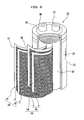
- FIG. 3 shows an example of an electric double-layer capacitor.
- an electric double-layer capacitor 31 is configured of, as main parts, a cylindrical container 32, an electrode winding body 33 that is housed in the container 32 and separated by band separators 47 and 48, and an electrolytic solution injected in the container 32.
- the container 32 is preferably formed of, for example, aluminum (alloy) from reasons of an easy workability, lightness in weight, and the like.
- the container 32 is configured of a cylindrical main body 34 with a bottom and a terminal plate 35 for closing one end opening of the cylindrical main body 34, and on the terminal plate 35 are provided a positive terminal 36 and a negative terminal 37.
- the electrode winding body 33 has a first band electrode 39 at a positive pole side and a second band electrode 40 at a negative pole side.
- the first band electrode 39 is an electrode where each of band polarizable electrodes e is pasted with a conductive adhesive on both sides of a band current collector 41 consisting of an aluminum foil, and a band positive pole 42 is configured of the polarizable electrodes e at both sides.
- the polarizable electrodes e are also called an active charcoal electrode and molded into a sheet from an active charcoal powder, a carbon black, a tetrafluoroethylene powder, and the like.
- the second band electrode 40 next described is same.
- the second band electrode 40 is an electrode where each of band polarizable electrodes e is pasted with a conductive adhesive on both sides of a band current collector 44 consisting of an aluminum foil, and a band negative pole 45 is configured of the polarizable electrodes e at both sides.
- the first band electrode body 39 at the positive pole side and the second band electrode body 40 at the negative pole side are separated by the separators 47 and 48 of the present invention. Because the separators 47 and 48 of the present invention are preferable in wetability for the electrolyte solvent such as the polypropylene carbonate that is strong in hydrophily, the electric double-layer capacitor 31 can preferably repeat a charging/discharging.
- the separators 47 and 48 of the present invention have a heat resistance endurable under a high temperature, they can be sufficiently dried before injecting the electrolytic solution. And because remaining moisture within the electric double-layer capacitor 31 can be made extremely little, the capacitor 31 becomes high in withstand voltage and energy density, and excellent in durability.
- the separators 47 and 48 of the present invention are light in surface density and thin in thickness, they can house the electrode winding body 33 more for a same volume and be made a large capacity.
- the separators 47 and 48 of the present invention have flexibility, they can be easily wound along a shape of the container 32.
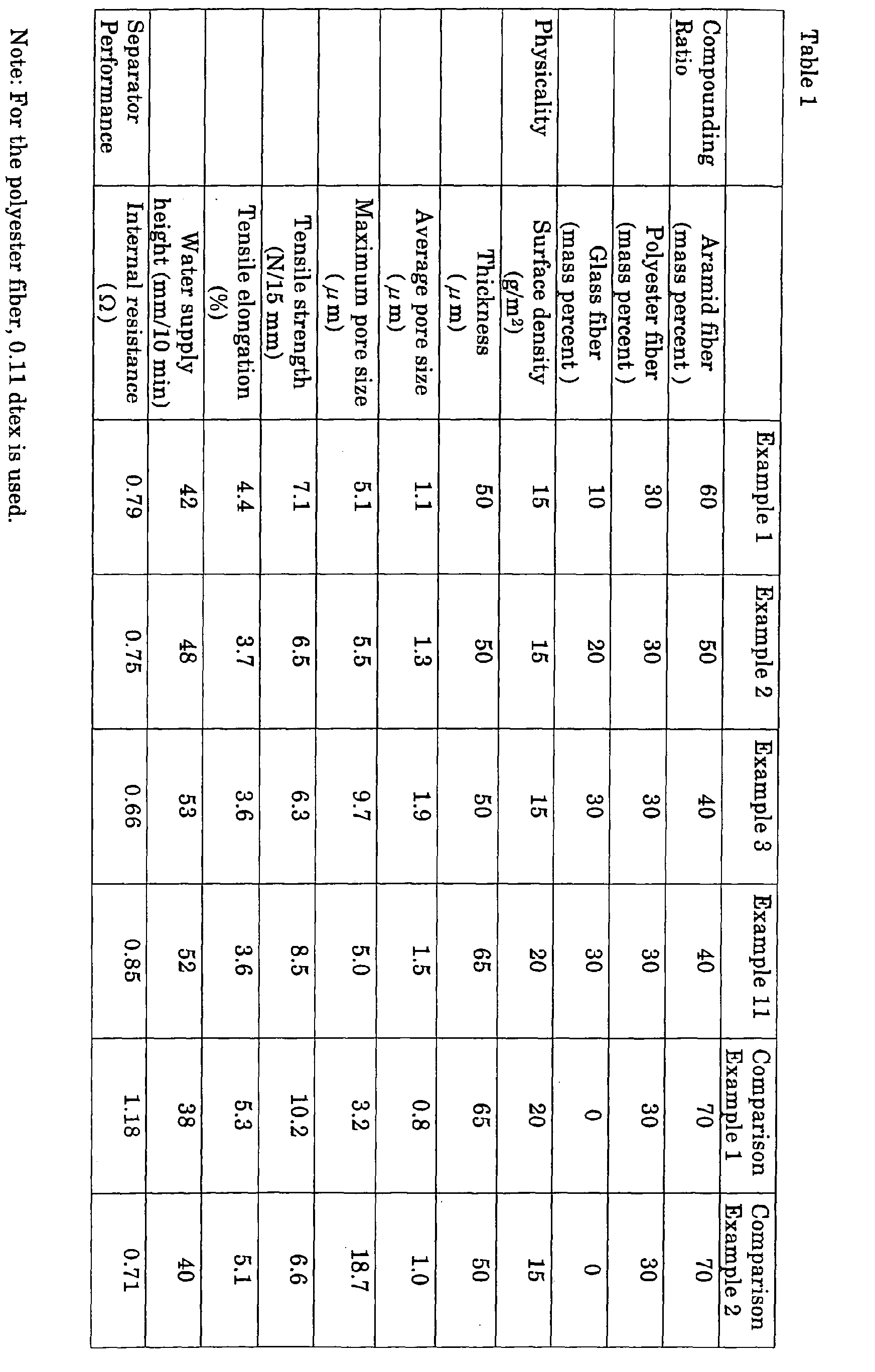
- each physicality of separators (examples 1 to 3: surface density, 15 g/m 2 ; thickness, 50 ⁇ m) made so as to make total mass of aramid fibers, polyester fibers, and glass fibers 100 'mass percent by making a polyester fiber compounding ratio constant, 30 mass percent, and changing a aramid fiber compounding ratio 60, 50, and 40 mass percent, and a glass fiber compounding ratio 10, 20, and 30 mass percent; a separator (example 11) whose surface density and thickness are made 20 g/m 2 ; thickness, 65 ⁇ m in the compounding ratio of the example 3; and conventional separators where the glass fibers are not contained (comparison example 1: aramid fibers, 70 mass percent; polyester fibers, 30 mass percent; surface density, 20 g/m 2 ; thickness, 65 ⁇ m; comparison example 2: aramid fibers, 70 mass percent; polyester fibers, 30 mass percent; surface density, 15 g/m 2 ; thickness, 50 ⁇ m).
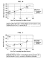
- FIGS. 6, 7, and 17 are shown relationships between the glass fiber compounding ratio and a water supply height; the glass fiber compounding ratio and a maximum pore size; and the glass fiber compounding ratio and an internal resistance, respectively.
- a girth of the glass fibers used for the examples 1 to 3 is 0.8 ⁇ m.
- the polyester fibers used for the examples 1 to 3 and the comparison example 1 are 0.11 dtex in denier and 3mm in fiber length.
- the aramid fibers are 0.2 ⁇ m to 0.3 ⁇ m in typical fiber diameter and 0.50 mm to 0.60 mm in typical fiber length.
- a measurement of the thickness is performed according to "JIS P 8118." The thinner the thickness is the more preferable the separators are because they can be housed in a container and the like in a larger amount.
- Measurements of the tensile strength and the tensile elongation are performed according to "JIS P 8113." The higher each of the tensile strength and the tensile elongation is the more preferable the separators are because the workability thereof is better.
- a measurement of the water supply height is performed according to "JIS P 8141.”
- polypropylene carbonate is used as a solvent.
- the internal resistance For a measurement of the internal resistance are prepared electrodes, where particle active charcoal, carbon black, and polytetrafluoroethylene are mixed and thoroughly kneaded; an aluminum foil as current collector electrodes; examples of the present invention and conventional comparison examples as separators; and an electrolytic solution where tetrafluoride boric acid tetraethyl ammonium is dissolved into propylene carbonate.
- the internal resistance is measured.
- the internal resistance is preferable to be lower because the lower the internal resistance is the smaller an energy loss of the electric double layer capacitor becomes.
- a pore size is measured by a bubble point method.
- the bubble point method is, as shown in FIG. 4, a method where a separator 53 of a test specimen is pinched with jigs 51 and 52 of a known porometer 50 through a packing 54 such as an O-ring; a gas is injected in a lower cavity 56 in a state where liquid such as water is filled in an upper cavity 55; bubbles, which occur by the gas passing through the separator 53, are checked with the porometer 50 (Automated Perm Porometer: manufactured by Porous Materials in the U.S.); and the pore size of the separator 53 is calculated according to a gas pressure and a surface tension of a liquid surface when the gas reaches a liquid surface as bubbles.
- the maximum pore size is preferable to be smaller.
- the examples 1 to 3 contain the glass fibers whose fiber diameter is smaller than that of the polyester fibers and larger than that of the aramid fibers, all of the separators of the examples 1 to 3 are easily made more uniform than the comparison example 2 consisting of the aramid fibers and the polyester fibers when the separators of the examples 1 to 3 are formed; and as a result, even in a separator of a low surface density the maximum pore size can be made a small value.
- the example 2 is larger in an average pore size and far smaller in the maximum pore size, compared to the comparison example 2. That is, that the average pore size is large and the maximum pore size becomes small shows that the aramid fibers, the polyester fibers, and the glass fibers are more uniformly dispersed and the separator is uniformly formed.
- separators whose maximum pore size is small and insulation property is excellent, can be obtained even in a same surface density, particularly in a region where the surface density is small.
- the maximum pore size tends to become larger.
- the maximum pore size can be made small by compounding the glass fibers, in the separators where the glass fibers are compounded the maximum pore size becomes large as the glass fiber compounding ratio is increased.
- the wetability and the pore sizes change in accordance with the glass fiber compounding ratio and the aramid fiber compounding ratio, it is requested to select the compounding ratios whose balance is good.
- it is desirable that the fiber diameters of the aramid fibers and the glass fibers are as small as possible.
- the maximum pore size becomes small, the wetability for the electrolytic solution can be heightened, and the maximum pore size can also be made significantly small in the region of the low surface density; however, as the glass fiber compounding ratio becomes high, the maximum pore size tends to become larger, and strength and elongation also tend to become lower.
- the aramid fibers can make the maximum pore size of the separators small as the compounding ratio thereof is heightened, on the other hand, the wetability for the electrolytic solution lowers. Furthermore, if the polyester fiber compounding ratio is less, the strength and elongation of the separators tend to become lower, so the polyester fibers are requested to keep the strength and elongation of the separators.
- the separators of the examples can be said to be optimum separators where the compounding ratio of each fiber is well balanced in the results previously described, that is, in wetability, maximum pore size, strength, and elongation.
- each physicality of separators (examples 3 to 5: surface density, 15 g/m 2 ; and thickness, 50 ⁇ m) made so as to make total mass of the aramid fibers, the polyester fibers, and the glass fibers 100 mass percent by making the glass fiber compounding ratio constant, 30 mass percent, and changing the aramid fiber compounding ratio 40, 50, and 55 mass percent, and the polyester fiber compounding ratio 30, 20, and 15 mass percent; the separators of the comparison example 2 described above and a comparison example 3 (aramid fibers, 60 mass percent; polyester fibers, 40 mass percent; surface density, 15 g/m 2 ; thickness, 50 ⁇ m).
- FIGS. 8 and 9 are shown relationships between the aramid fiber compounding ratio and the water supply height, and the aramid fiber compounding ratio and the maximum pore size, respectively.
- the glass fibers used for the examples 3 to 5 is 0.8 ⁇ m in girth and the polyester fibers is 0.11 dtex in denier and is 3 mm in fiber length.
- the aramid fibers are 0.2 ⁇ m to 0.3 ⁇ m in typical fiber diameter and 0.50 mm to 0.60 mm in typical fiber length.
- defoaming agents such as Pronal (manufactured by TOHO Chemical Industry Co., Ltd.), KM (Shin-Etsu Chemical Co., Ltd.), Foamless (R) (Meisei Chemical Works, Ltd.), and the like, and stir them.
- a styrene acryl acid polyester copolymer resin (hereinafter abbreviated to the "resin") of 0.34 g and stirring it, as a cation fixing reinforcement agent (binder) add a polyamide epichlorohydrin of 2.0 g and stir it.
- slurry where the aramid fibers, the glass fibers, the polyester fibers, and the like are mixed, is made into paper by the hand paper making machine (square hand paper standard machine manufactured by Kumagai Riki Ltd.), and a separator, whose surface density is 15 g/m 2 and thickness is 50 ⁇ m, is obtained.
- the mixed fibers can be more uniformly dispersed, a separator, where all fibers are uniformly intertwined, can be formed, and the strength and elongation of the separator can be improved because the resin can be fixed in a state, where it is uniformly intertwined with all fibers thanks to a use of the resin and the cation fixing reinforcement agent as the binders, when the fibers are dispersed in the water.
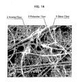
- FIG. 14 a photo of the separator by a scanning electronic microscope (SEM) related to the example 4 is shown in FIG. 14.
- the separator is configured, with the aramid fibers 2, the polyester fibers (PET fibers) 3 whose fiber diameter is comparatively large, and the glass fibers 4 whose fiber diameter is smaller than that of the polyester fibers 3 and larger than that of the aramid fibers 2 being intertwined and bonded each other.
- the maximum pore size is large as it is in the surface density of 15 g/m 2 without depending on the aramid fiber compounding ratio.
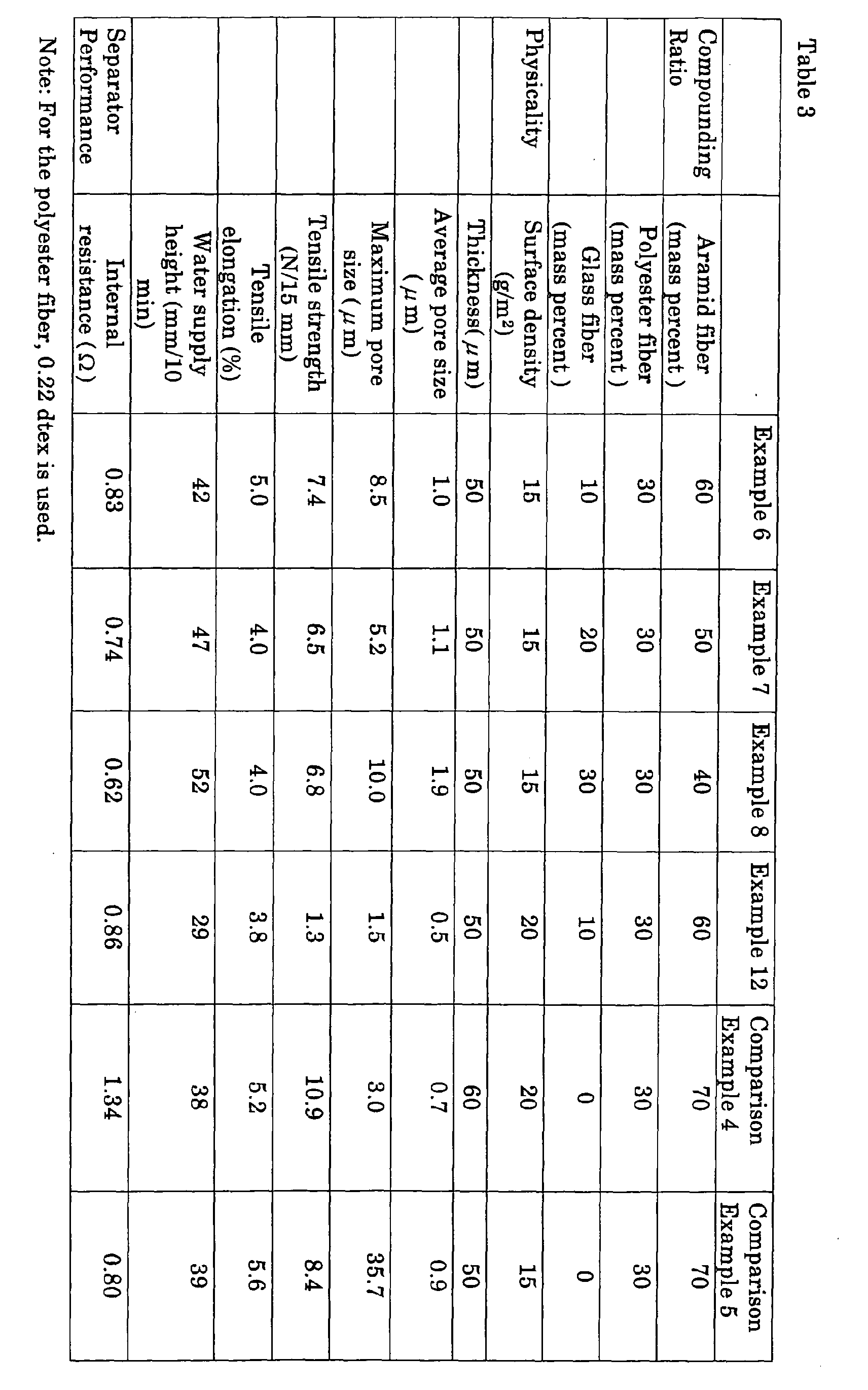
- each physicality of separators (examples 6 to 8: surface density, 15 g/m 2 ; thickness, 50 ⁇ m) made so as to make total mass of the aramid fibers, the polyester fibers, and the glass fibers 100 mass percent by making the polyester fiber compounding ratio of a different kind of polyester fibers (denier, 0.22 dtex; and fiber length, 3 mm) from the polyester fibers used for the examples 1 to 3 (denier, 0.11 dtex; and fiber length, 3 mm) constant, 30 mass percent, and changing the aramid fiber compounding ratio 60, 50, and 40 mass percent, and the glass fiber compounding ratio 10, 20, and 30 mass percent, same as in the examples 1 to 3; a separator of an example 12 described later; and conventional separators where no glass fibers are contained (comparison example 4: aramid fibers, 70 mass percent; polyester fibers, 30 mass percent; surface density, 20 g/m 2 ; and thickness, 60 ⁇ m; comparison example 5: aramid fiber
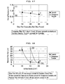
- FIGS. 10, 11, 12, and 13 are shown relationships between the glass fiber compounding ratio and the water supply height; the glass fiber compounding ratio and the maximum pore size; the glass fiber compounding ratio and the tensile elongation; and the glass fiber compounding ratio and the internal resistance, respectively.
- the glass fibers used for the examples 6 to 8 is 0.8 ⁇ m in girth.
- the aramid fibers are 0.2 ⁇ m to 0.3 ⁇ m in the typical fiber diameter and 0.50 mm to 0.60 mm in the typical fiber length.
- the surface density is made constant, 15 g/m 2 , and the thickness is designed to be 50 ⁇ m.
- the example 12 is made same in a compounding ratio of each fiber as in the example 6 and is made so that the surface density becomes 20 g/m 2 and the thickness becomes 50 ⁇ m.
- the example 12 is made as follows:
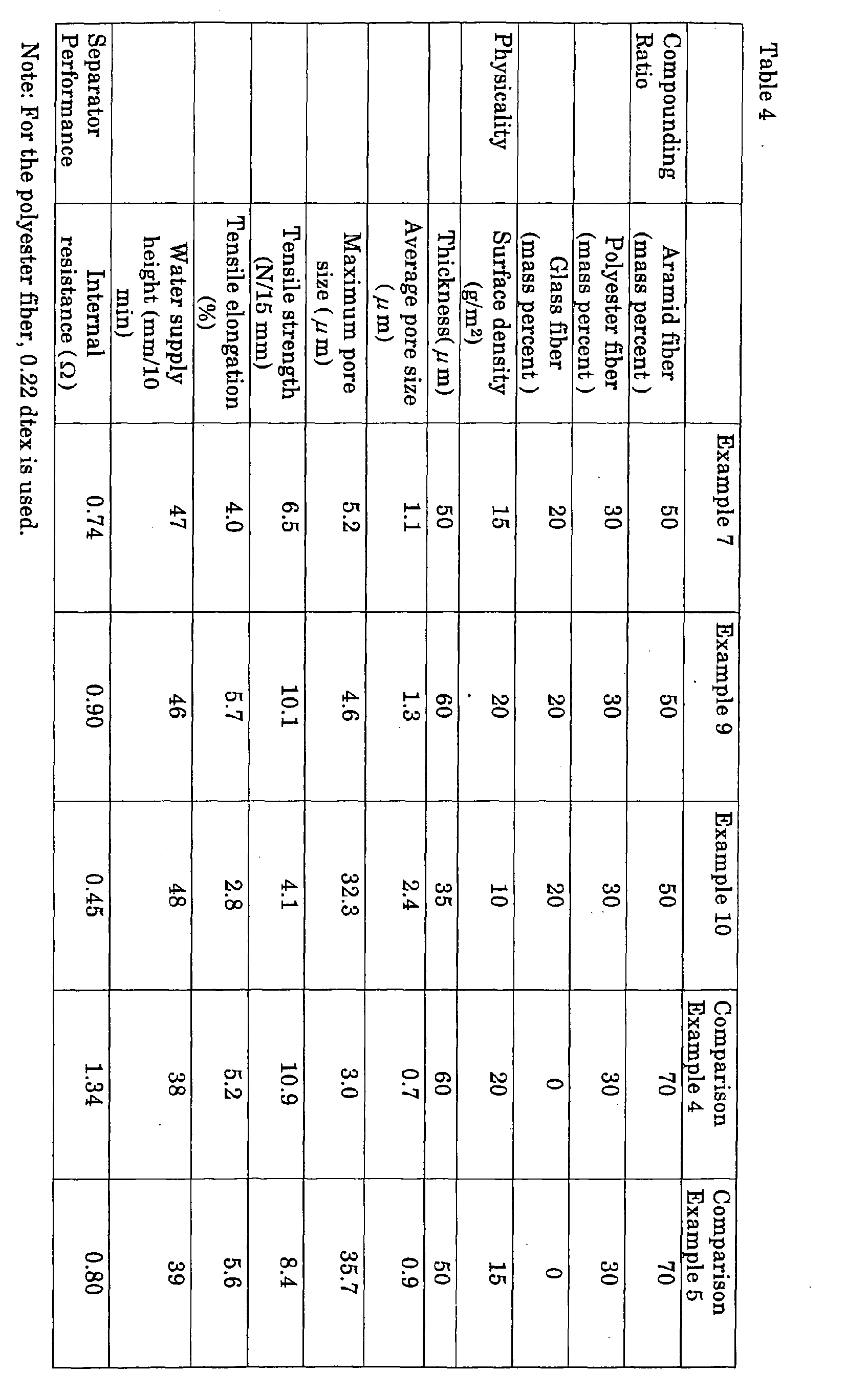
- each physicality of separators (examples 7, 9, and 10) made by changing the surface density 15, 20, and 10 g/m 2 of separators whose aramid fibers composition ratio, polyester fiber compounding ratio and glass fiber compounding ratio, are 50, 30, and 20 mass percent, respectively.
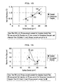
- FIG. 15 a relationship between the surface density and internal resistance of the examples 7, 9, and 10 is shown in conjunction with the comparison examples 4 and 5.
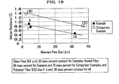
- FIGS. 18 and 19 are shown relationships between the surface density and the maximum pore size, and the maximum pore size and the internal resistance, respectively.
- the glass fibers used for the examples 7, 9, and 10 is 0.8 ⁇ m in girth
- the polyester fibers are 0.22 dtex in denier and 3 mm in fiber length.
- the aramid fibers are 0.2 ⁇ m to 0.3 ⁇ m in the typical fiber diameter and 0.50 mm to 0.60 mm in the typical fiber length.
- the thickness of the separators can be made thinner by making the surface density thereof smaller.
- the separators whose internal resistances are lower can be formed while making the maximum pore size smaller.
- each physicality of a separator that contains an aramid fiber, polyester fiber, glass fiber, and silica of 50, 20, 20, and 10 mass percent in their compounding ratios, respectively, and total thereof is designed to be 100 mass percent
- another separator that contains an aramid fiber, polyester fiber, and silica of 64, 27, and 9 mass percent in their compounding ratios, respectively, and total thereof is designed to be 100 mass percent
- still another separator that contains an aramid fiber, polyester fiber, glass fiber of 50, 20, and 30 mass percent in their compounding ratios, respectively, without containing the silica
- a conventional separator not containing the silica (comparison example 6: the aramid fiber compounding ratio, and 70 mass percent; the polyester fiber compounding ratio, 30 mass percent).
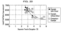
- FIG. 20 shows a relationship between a liquid hold ratio and a tensile elongation.
- the aramid fibers used for the examples 13 to 15 and the comparison example 6 are 0.2 ⁇ m to 0.3 ⁇ m in the typical fiber diameter and 0.50 mm to 0.60 mm in the typical fiber length.
- the polyester fibers used for the examples 13 to 15 and the comparison example 6 are 0.11 dtex and 3 mm in fiber diameter and fiber length, respectively.
- the glass fibers used for the examples 13 and 15 are 0.8 ⁇ m in fiber diameter.
- the surface density of the separators is made constant, 20 g/m 2 and the thickness thereof is designed to be about 60 ⁇ m.
- a particle diameter of particulate silicas in the silica sol is 10 nm to 20 nm by the BET (Brunauer, Emmett, and Teller) method.
- Example 13 Example 14
- Example 15 Comparison Example 6 Compounding Ratio Aramid fiber (mass percent) 50 64 50 70 Polyester fiber (mass percent ) 20 27 20 30 Glass fiber (mass percent ) 20 0 30 0 Silica (mass percent ) 10 9 0 0 Physicality Surface density (g/m 2 ) 20 20 20 20 20 Thickness( ⁇ m) 60 55 60 60 60 Maximum pore size ( ⁇ m) 3.2 3.3 4.1 3.2 Tensile strength (N/15 mm) 7.6 6.9 8.4 10.2 Tensile elongation (%) 2.9 3.8 3.1 5.3 Ash (%) 26.9 - 27.9 0.448 Liquid hold ratio (%) 650 590 640 560 Internal resistance ( ⁇ ) 0.82 - 0.93 1.18 Voltage keep ratio ( ⁇ ) 650 590 640 560
- Table 5 a measurement of the ash is performed according to "JIS P 8128.”
- the measured value corresponds to total amount of the glass fibers and the silcas in the silica sol contained in the separators.
- the liquid hold ratio is preferable to be higher.
- V1 a potential difference between positive and negative electrodes becomes constant
- V2 a potential difference between the positive and negative electrodes after being left in an insulation state for a constant time
- V2/V1 a ratio of the potential differences in percent direct after the charge
- the voltage keep ratio is preferable to be higher.
- the liquid hold ratio thereof can be improved while suppressing the lowering of the tensile elongation and the tensile strength by further compounding the silicas and replacing the glass fibers and the like with the silicas.
- the fibers configuring the separator 1 are assumed to be the aramid fibers 2, the polyester fibers 3, and the glass fibers 4, combinations and kinds of the fibers are not limited thereto: for example, as another combination, selecting the aramid fibers 2 and the polyester fibers 3, is available a separator 1 where the silicas 5 adhere to surfaces thereof,; and for example, as another kind is also available another separator 1 where the silicas 5 adhere to celluloses.
- the silicas 5 are independently used as an inorganic compound for forming hydrosol, other than this, for example, alumina (Al 2 O 3 ) may be used, and the silicas 5 and the alumina may be used in combination.
- alumina Al 2 O 3
- alumina sol usage In use of the alumina an alumina sol usage is available, and is cited alumina sol (manufactured by Nissan Chemical Industries Ltd.) and the like.
- the making method of the separator 1 for the electric double-layer capacitor is according to making the silicas 5 adhere to the surface of the separator 1 by adding the silica sol 22 to the aramid fibers 2, the polyester fibers 3, and the glass fibers 4 while mixing; then mixing them; and making paper: however, for example, other than this, making another separator 1 formed with containing the aramid fibers 2, the polyester fibers 3, and the glass fibers 4, and then coating the silica sol 22 on the surface of the separator 1 by using, for example, a brush, thereby making the silicas 5 adhere to the separator 1, and the separator 1 may be made; and still another separator 1 may also be made according to an impregnation adherence method for making the silicas 5 adhere to the separator 1 by impregnating it in the silica sol 22.
- the separator (hereinafter referred to as the "raw paper separator"), which becomes raw paper by a paper making machine, in an impregnation tank where silica sol of 1 mass percent to 40 mass percent is filled, pass the separator between two rolls that rotate in pressure-contact with each other, wring extra silica sol, adjust an adherence amount of the silicas to the separator from 1 mass percent to 20 mass percent in a solid content, and then dry the separator at 100 to 150 degrees Celsius. Because the separator thus obtained can use the raw paper separator manufactured by a usual paper manufacturing method as it is, a manufacturing efficiency thereof is excellent.
- This separator is made an example 16 and physicality thereof is shown in Table 6 in conjunction with the raw paper separator.
- Raw Paper Separator Example 16 Compounding Ratio Aramid fiber (mass percent) 50 45 Polyester fiber (mass percent) 20 18 Glass fiber (mass percent) 30 27 Silica (mass percent ) 0 10 Physicality Surface density (g/m 2 ) 15 17 Thickness( ⁇ m) 35 36 Maximum pore size ( ⁇ m) 2.3 2.5 Tensile strength (N/15 mm) 10.8 14.7 Tensile elongation (%) 3.2 2.0
- the present invention is mainly configured of a separator for an electric double-layer capacitor that comprises an aramid fiber, a polyester fiber, a glass fiber, and a silica (inorganic compound for forming hydrosol) containing a particulate silica (particulate inorganic compound) of not less than 1 nm and not more than 500 nm, wherein total of the silica and the glass fiber is not less than 10 mass percent and not more than 50 mass percent; the electric double-layer capacitor comprising the separator; and a manufacturing method of the separator for the electric double-layer capacitor which method comprises a mixing process for mixing the aramid fiber, the polyester fiber, the glass fiber, and the silica sol and a paper making process for making paper from the mixture.
Landscapes
- Engineering & Computer Science (AREA)
- Power Engineering (AREA)
- Microelectronics & Electronic Packaging (AREA)
- Electric Double-Layer Capacitors Or The Like (AREA)
Abstract
Description

In addition, from Table 2 and FIG. 9, it turns out that in the separators of the examples 3 to 5 the maximum pore size tends to become smaller as the aramid fiber compounding ratio increases.
| Example 13 | Example 14 | Example 15 | Comparison Example 6 | ||
| Compounding Ratio | Aramid fiber (mass percent) | 50 | 64 | 50 | 70 |
| Polyester fiber (mass percent ) | 20 | 27 | 20 | 30 | |
| Glass fiber (mass percent ) | 20 | 0 | 30 | 0 | |
| Silica (mass percent ) | 10 | 9 | 0 | 0 | |
| Physicality | Surface density (g/m2) | 20 | 20 | 20 | 20 |
| Thickness(µm) | 60 | 55 | 60 | 60 | |
| Maximum pore size (µm) | 3.2 | 3.3 | 4.1 | 3.2 | |
| Tensile strength (N/15 mm) | 7.6 | 6.9 | 8.4 | 10.2 | |
| Tensile elongation (%) | 2.9 | 3.8 | 3.1 | 5.3 | |
| Ash (%) | 26.9 | - | 27.9 | 0.448 | |
| Liquid hold ratio (%) | 650 | 590 | 640 | 560 | |
| Internal resistance (Ω) | 0.82 | - | 0.93 | 1.18 | |
| Voltage keep ratio (%) | 91 | - | 90 | - |
| Raw Paper Separator | Example 16 | ||
| Compounding Ratio | Aramid fiber (mass percent) | 50 | 45 |
| Polyester fiber (mass percent) | 20 | 18 | |
| Glass fiber (mass percent) | 30 | 27 | |
| Silica (mass percent ) | 0 | 10 | |
| Physicality | Surface density (g/m2) | 15 | 17 |
| Thickness(µm) | 35 | 36 | |
| Maximum pore size (µm) | 2.3 | 2.5 | |
| Tensile strength (N/15 mm) | 10.8 | 14.7 | |
| Tensile elongation (%) | 3.2 | 2.0 |
Claims (81)
- A separator for an electric double-layer capacitor comprising:a glass fiber;a polyester fiber; andan aramid fiber.
- A separator for an electric double-layer capacitor according to claim 1 which separator contains said glass fiber of not less than 10 mass percent and not more than 40 mass percent.
- A separator for an electric double-layer capacitor according to claim 1 which separator contains said aramid fiber of not less than 40 mass percent and not more than 60 mass percent.
- A separator for an electric double-layer capacitor according to claim 2 which separator contains said aramid fiber of not less than 40 mass percent and not more than 60 mass percent.
- A separator for an electric double-layer capacitor according to claim 1 which separator contains said polyester fiber of not less than 10 mass percent and not more than 30 mass percent.
- A separator for an electric double-layer capacitor according to claim 2 which separator contains said polyester fiber of not less than 10 mass percent and not more than 30 mass percent.
- A separator for an electric double-layer capacitor according to claim 3 which separator contains said polyester fiber of not less than 10 mass percent and not more than 30 mass percent.
- A separator for an electric double-layer capacitor according to claim 4 which separator contains said polyester fiber of not less than 10 mass percent and not more than 30 mass percent.
- A separator for an electric double-layer capacitor according to claim 1 which separator comprises an acryl resin and a cation fixing reinforcement agent as a binder for binding said glass fiber, said polyester fiber, and said aramid fiber, wherein paper making is performed.
- A separator for an electric double-layer capacitor according to claim 2 which separator comprises an acryl resin and a cation fixing reinforcement agent as a binder for binding said glass fiber, said polyester fiber, and said aramid fiber, wherein paper making is performed.
- A separator for an electric double-layer capacitor according to claim 3 which separator comprises an acryl resin and a cation fixing reinforcement agent as a binder for binding said glass fiber, said polyester fiber, and said aramid fiber, wherein paper making is performed.
- A separator for an electric double-layer capacitor according to claim 4 which separator comprises an acryl resin and a cation fixing reinforcement agent as a binder for binding said glass fiber, said polyester fiber, and said aramid fiber, wherein paper making is performed.
- A separator for an electric double-layer capacitor according to claim 5 which separator comprises an acryl resin and a cation fixing reinforcement agent as a binder for binding said glass fiber, said polyester fiber, and said aramid fiber, wherein paper making is performed.
- A separator for an electric double-layer capacitor according to claim 6 which separator comprises an acryl resin and a cation fixing reinforcement agent as a binder for binding said glass fiber, said polyester fiber, and said aramid fiber, wherein paper making is performed.
- A separator for an electric double-layer capacitor according to claim 7 which separator comprises an acryl resin and a cation fixing reinforcement agent as a binder for binding said glass fiber, said polyester fiber, and said aramid fiber, wherein paper making is performed.
- A separator for an electric double-layer capacitor according to claim 8 which separator comprises an acryl resin and a cation fixing reinforcement agent as a binder for binding said glass fiber, said polyester fiber, and said aramid fiber, wherein paper making is performed.
- A separator for an electric double-layer capacitor according to claim 1, wherein a surface density is not less than 10 g/m2 and not more than 30 g/m2 and a thickness is not less than 20 µm and not more than 60 µm.
- A separator for an electric double-layer capacitor according to claim 2, wherein a surface density is not less than 10 g/m2 and not more than 30 g/m2 and a thickness is not less than 20 µm and not more than 60 µm.
- A separator for an electric double-layer capacitor according to claim 3, wherein a surface density is not less than 10 g/m2 and not more than 30 g/m2 and a thickness is not less than 20 µm and not more than 60 µm.
- A separator for an electric double-layer capacitor according to claim 4, wherein a surface density is not less than 10 g/m2 and not more than 30 g/m2 and a thickness is not less than 20 µm and not more than 60 µm.
- A separator for an electric double-layer capacitor according to claim 5, wherein a surface density is not less than 10 g/m2 and not more than 30 g/m2 and a thickness is not less than 20 µm and not more than 60 µm.
- A separator for an electric double-layer capacitor according to claim 6, wherein a surface density is not less than 10 g/m2 and not more than 30 g/m2 and a thickness is not less than 20 µm and not more than 60 µm.
- A separator for an electric double-layer capacitor according to claim 7, wherein a surface density is not less than 10 g/m2 and not more than 30 g/m2 and a thickness is not less than 20 µm and not more than 60 µm.
- A separator for an electric double-layer capacitor according to claim 8, wherein a surface density is not less than 10 g/m2 and not more than 30 g/m2 and a thickness is not less than 20 µm and not more than 60 µm.
- A separator for an electric double-layer capacitor according to claim 9, wherein a surface density is not less than 10 g/m2 and not more than 30 g/m2 and a thickness is not less than 20 µm and not more than 60 µm.
- A separator for an electric double-layer capacitor according to claim 10, wherein a surface density is not less than 10 g/m2 and not more than 30 g/m2 and a thickness is not less than 20 µm and not more than 60 µm.
- A separator for an electric double-layer capacitor according to claim 11, wherein a surface density is not less than 10 g/m2 and not more than 30 g/m2 and a thickness is not less than 20 µm and not more than 60 µm.
- A separator for an electric double-layer capacitor according to claim 12, wherein a surface density is not less than 10 g/m2 and not more than 30 g/m2 and a thickness is not less than 20 µm and not more than 60 µm.
- A separator for an electric double-layer capacitor according to claim 13, wherein a surface density is not less than 10 g/m2 and not more than 30 g/m2 and a thickness is not less than 20 µm and not more than 60 µm.
- A separator for an electric double-layer capacitor according to claim 14, wherein a surface density is not less than 10 g/m2 and not more than 30 g/m2 and a thickness is not less than 20 µm and not more than 60 µm.
- A separator for an electric double-layer capacitor according to claim 15, wherein a surface density is not less than 10 g/m2 and not more than 30 g/m2 and a thickness is not less than 20 µm and not more than 60 µm.
- A separator for an electric double-layer capacitor according to claim 16, wherein a surface density is not less than 10 g/m2 and not more than 30 g/m2 and a thickness is not less than 20 µm and not more than 60 µm.
- A separator for an electric double-layer capacitor comprising:a fiber; andan inorganic compound for forming hydrosol that is made to adhere to a surface of said fiber.
- A separator for an electric double-layer capacitor according to claim 33 which separator contains said inorganic compound of not less than 1 mass percent and not more than 20 mass percent.
- A separator for an electric double-layer capacitor according to claim 33, wherein said inorganic compound comprises a particulate inorganic compound and a particle diameter of said particulate inorganic compound is not less than 1 nm and not more than 500 nm.
- A separator for an electric double-layer capacitor according to claim 34, wherein said inorganic compound comprises a particulate inorganic compound and a particle diameter of said particulate inorganic compound is not less than 1 nm and not more than 500 nm.
- A separator for an electric double-layer capacitor according to claim 33, wherein said fiber comprises at least a glass fiber, and wherein total of said inorganic compound and said glass fiber is not less than 10 mass percent and not more than 50 mass percent.
- A separator for an electric double-layer capacitor according to claim 34, wherein said fiber comprises at least a glass fiber, and wherein total of said inorganic compound and said glass fiber is not less than 10 mass percent and not more than 50 mass percent.
- A separator for an electric double-layer capacitor according to claim 35, wherein said fiber comprises at least a glass fiber, and wherein total of said inorganic compound and said glass fiber is not less than 10 mass percent and not more than 50 mass percent.
- A separator for an electric double-layer capacitor according to claim 36, wherein said fiber comprises at least a glass fiber, and wherein total of said inorganic compound and said glass fiber is not less than 10 mass percent and not more than 50 mass percent.
- An electric double-layer capacitor comprising a separator therefor according to claim 1.
- An electric double-layer capacitor comprising a separator therefor according to claim 2.
- An electric double-layer capacitor comprising a separator therefor according to claim 3.
- An electric double-layer capacitor comprising a separator therefor according to claim 4.
- An electric double-layer capacitor comprising a separator therefor according to claim 5.
- An electric double-layer capacitor comprising a separator therefor according to claim 6.
- An electric double-layer capacitor comprising a separator therefor according to claim 7.
- An electric double-layer capacitor comprising a separator therefor according to claim 8.
- An electric double-layer capacitor comprising a separator therefor according to claim 9.
- An electric double-layer capacitor comprising a separator therefor according to claim 10.
- An electric double-layer capacitor comprising a separator therefor according to claim 11.
- An electric double-layer capacitor comprising a separator therefor according to claim 12.
- An electric double-layer capacitor comprising a separator therefor according to claim 13.
- An electric double-layer capacitor comprising a separator therefor according to claim 14.
- An electric double-layer capacitor comprising a separator therefor according to claim 15.
- An electric double-layer capacitor comprising a separator therefor according to claim 16.
- An electric double-layer capacitor comprising a separator therefor according to claim 17.
- An electric double-layer capacitor comprising a separator therefor according to claim 18.
- An electric double-layer capacitor comprising a separator therefor according to claim 19.
- An electric double-layer capacitor comprising a separator therefor according to claim 20.
- An electric double-layer capacitor comprising a separator therefor according to claim 21.
- An electric double-layer capacitor comprising a separator therefor according to claim 22.
- An electric double-layer capacitor comprising a separator therefor according to claim 23.
- An electric double-layer capacitor comprising a separator therefor according to claim 24.
- An electric double-layer capacitor comprising a separator therefor according to claim 25.
- An electric double-layer capacitor comprising a separator therefor according to claim 26.
- An electric double-layer capacitor comprising a separator therefor according to claim 27.
- An electric double-layer capacitor comprising a separator therefor according to claim 28.
- An electric double-layer capacitor comprising a separator therefor according to claim 29.
- An electric double-layer capacitor comprising a separator therefor according to claim 30.
- An electric double-layer capacitor comprising a separator therefor according to claim 31.
- An electric double-layer capacitor comprising a separator therefor according to claim 32.
- An electric double-layer capacitor comprising a separator therefor according to claim 33.
- An electric double-layer capacitor comprising a separator therefor according to claim 34.
- An electric double-layer capacitor comprising a separator therefor according to claim 35.
- An electric double-layer capacitor comprising a separator therefor according to claim 36.
- An electric double-layer capacitor comprising a separator therefor according to claim 37.
- An electric double-layer capacitor comprising a separator therefor according to claim 38.
- An electric double-layer capacitor comprising a separator therefor according to claim.
- An electric double-layer capacitor comprising a separator therefor according to claim 40.
- A manufacturing method of a separator for an electric double-layer capacitor, the method comprising;
a mixing process for mixing a fiber and an inorganic compound that forms hydrosol and is dispersed; and
a paper making process for making paper from said mixed fiber and inorganic compound.
Applications Claiming Priority (2)
| Application Number | Priority Date | Filing Date | Title |
|---|---|---|---|
| JP2003146935A JP2004349586A (en) | 2003-05-23 | 2003-05-23 | Separator for electric double layer capacitor, electric double layer capacitor, and method for producing separator for electric double layer capacitor |
| JP2003146935 | 2003-05-23 |
Publications (2)
| Publication Number | Publication Date |
|---|---|
| EP1480237A2 true EP1480237A2 (en) | 2004-11-24 |
| EP1480237A3 EP1480237A3 (en) | 2006-06-07 |
Family
ID=33095503
Family Applications (1)
| Application Number | Title | Priority Date | Filing Date |
|---|---|---|---|
| EP04012094A Withdrawn EP1480237A3 (en) | 2003-05-23 | 2004-05-21 | Separator for electric double-layer capacitor, electric double-layer capacitor, and manufacturing method of separator for electric double-layer capacitor |
Country Status (3)
| Country | Link |
|---|---|
| US (1) | US6937459B2 (en) |
| EP (1) | EP1480237A3 (en) |
| JP (1) | JP2004349586A (en) |
Cited By (2)
| Publication number | Priority date | Publication date | Assignee | Title |
|---|---|---|---|---|
| EP2849258A4 (en) * | 2012-05-09 | 2015-12-30 | Hitachi Chemical Co Ltd | SEPARATOR FOR ELECTROCHEMICAL ELEMENT AND METHOD OF MANUFACTURING THE SAME |
| CN109750552A (en) * | 2018-12-04 | 2019-05-14 | 株洲时代新材料科技股份有限公司 | A kind of aluminium electrolutic capacitor paper |
Families Citing this family (9)
| Publication number | Priority date | Publication date | Assignee | Title |
|---|---|---|---|---|
| JP4864427B2 (en) * | 2005-11-16 | 2012-02-01 | ローム株式会社 | Manufacturing method of electric double layer capacitor |
| CN1983676A (en) * | 2006-01-27 | 2007-06-20 | 松下电器产业株式会社 | Lithium ion secondary battery and charge system therefor |
| US7990679B2 (en) * | 2006-07-14 | 2011-08-02 | Dais Analytic Corporation | Nanoparticle ultracapacitor |
| WO2010028162A2 (en) * | 2008-09-04 | 2010-03-11 | The Regents Of The University Of California | Charge storage device architecture for increasing energy and power density |
| JP5113685B2 (en) * | 2008-09-09 | 2013-01-09 | 三菱製紙株式会社 | Electrochemical element separator |
| DE102009028145A1 (en) | 2009-07-31 | 2011-02-03 | Evonik Degussa Gmbh | Ceramic membranes with polyaramid fiber-containing support materials and process for making these membranes |
| US9412986B2 (en) * | 2013-07-31 | 2016-08-09 | GM Global Technology Operations LLC | Porous composite structures for lithium-ion battery separators |
| EP4293693A4 (en) * | 2021-02-09 | 2025-06-11 | Nippon Chemi-Con Corporation | CAPACITOR |
| CN113131097A (en) * | 2021-03-24 | 2021-07-16 | 宁德新能源科技有限公司 | Battery cell and power utilization device |
Family Cites Families (7)
| Publication number | Priority date | Publication date | Assignee | Title |
|---|---|---|---|---|
| JP3416992B2 (en) * | 1993-07-12 | 2003-06-16 | 日本板硝子株式会社 | Sealed lead-acid battery separator |
| CN1148815C (en) * | 1995-03-31 | 2004-05-05 | 三菱制纸株式会社 | Nonwoven fabric for nonaqueous electrolyte battery and nonaqueous electrolyte battery using the same |
| US5709798A (en) * | 1995-06-19 | 1998-01-20 | Pall Corporation | Fibrous nonwoven web |
| JPH0931883A (en) | 1995-07-24 | 1997-02-04 | Daifuku Seishi Kk | Paper containing heat-resistant fiber blended therein |
| JP3845536B2 (en) | 1999-12-24 | 2006-11-15 | 日本バイリーン株式会社 | Manufacturing method of electric double layer capacitor |
| JP3717782B2 (en) | 1999-12-24 | 2005-11-16 | 日本バイリーン株式会社 | Electric double layer capacitor separator |
| WO2001093350A1 (en) * | 2000-05-29 | 2001-12-06 | Mitsubishi Paper Mills Limited | Separator for electrochemical device and method for producing the same, and electrochemical device |
-
2003
- 2003-05-23 JP JP2003146935A patent/JP2004349586A/en active Pending
-
2004
- 2004-05-20 US US10/849,505 patent/US6937459B2/en not_active Expired - Fee Related
- 2004-05-21 EP EP04012094A patent/EP1480237A3/en not_active Withdrawn
Cited By (2)
| Publication number | Priority date | Publication date | Assignee | Title |
|---|---|---|---|---|
| EP2849258A4 (en) * | 2012-05-09 | 2015-12-30 | Hitachi Chemical Co Ltd | SEPARATOR FOR ELECTROCHEMICAL ELEMENT AND METHOD OF MANUFACTURING THE SAME |
| CN109750552A (en) * | 2018-12-04 | 2019-05-14 | 株洲时代新材料科技股份有限公司 | A kind of aluminium electrolutic capacitor paper |
Also Published As
| Publication number | Publication date |
|---|---|
| EP1480237A3 (en) | 2006-06-07 |
| US20040264108A1 (en) | 2004-12-30 |
| US6937459B2 (en) | 2005-08-30 |
| JP2004349586A (en) | 2004-12-09 |
Similar Documents
| Publication | Publication Date | Title |
|---|---|---|
| US11804634B2 (en) | Battery components comprising fibers | |
| EP3281241B1 (en) | Battery separators comprising inorganic particles | |
| US9614249B2 (en) | Separator for non-aqueous electrolyte secondary battery and non-aqueous electrolyte secondary battery | |
| CN102884654B (en) | Hermetic type lead accumulator dividing plate and hermetic type lead accumulator | |
| US6937459B2 (en) | Separator for electric double-layer capacitor, electric double-layer capacitor, and manufacturing method of separator for electric double-layer capacitor | |
| US20190393464A1 (en) | Pasting papers and capacitance layers for batteries comprising multiple fiber types and/or particles | |
| EP3425698B1 (en) | Alkaline battery separator and alkaline battery | |
| US10283746B2 (en) | Small pore size nonwoven mat with hydrophilic/acid resistant filler used in lead acid batteries and applications therefor | |
| EP2619365A2 (en) | Compositions and delivery systems with leachable metal ions | |
| US20190181410A1 (en) | Pasting papers and capacitance layers for batteries comprising multiple fiber types and/or particles | |
| WO2011146271A1 (en) | Surface modified glass fibers | |
| EP4721184A2 (en) | Fine glass fibers and fiber webs, separators, and pasting papers comprising them | |
| JP6739946B2 (en) | Alkaline battery separator and alkaline battery | |
| WO2019188659A1 (en) | Separator for aluminum electrolytic capacitors, and aluminum electrolytic capacitor | |
| JP6739947B2 (en) | Alkaline battery separator and alkaline battery | |
| JP7846550B2 (en) | Support for secondary batteries, and secondary batteries | |
| JP2004207261A (en) | Electric double layer capacitor separator and electric double layer capacitor | |
| JPWO2016121511A1 (en) | Lead-acid battery separator and lead-acid battery | |
| JP4490732B2 (en) | Electric double layer capacitor separator and electric double layer capacitor | |
| CN113711417A (en) | Use of lignosulfonates and high surface area carbon in enhanced flooded and VRLA AGM batteries for battery separator members with high charge acceptance | |
| JPS6180750A (en) | Separator for sealed type lead storage battery | |
| Ihmels et al. | LEAD-ACID BATTERIES |
Legal Events
| Date | Code | Title | Description |
|---|---|---|---|
| PUAI | Public reference made under article 153(3) epc to a published international application that has entered the european phase |
Free format text: ORIGINAL CODE: 0009012 |
|
| AK | Designated contracting states |
Kind code of ref document: A2 Designated state(s): AT BE BG CH CY CZ DE DK EE ES FI FR GB GR HU IE IT LI LU MC NL PL PT RO SE SI SK TR |
|
| AX | Request for extension of the european patent |
Extension state: AL HR LT LV MK |
|
| RIN1 | Information on inventor provided before grant (corrected) |
Inventor name: NAGAO, HIROSHI Inventor name: KOMAZAWA, EISUKE Inventor name: NOGUCHI, MINORU Inventor name: YANAGI, KAZUHIKO Inventor name: SUZUKI, MITSUTOSHI Inventor name: YAMAZAKI, KOUJI |
|
| RIN1 | Information on inventor provided before grant (corrected) |
Inventor name: MATSUDA, MICHIO Inventor name: NAGAO, HIROSHI Inventor name: KOMAZAWA, EISUKE Inventor name: NOGUCHI, MINORU Inventor name: YANAGI, KAZUHIKO Inventor name: SUZUKI, MITSUTOSHI Inventor name: YAMAZAKI, KOUJI |
|
| PUAL | Search report despatched |
Free format text: ORIGINAL CODE: 0009013 |
|
| AK | Designated contracting states |
Kind code of ref document: A3 Designated state(s): AT BE BG CH CY CZ DE DK EE ES FI FR GB GR HU IE IT LI LU MC NL PL PT RO SE SI SK TR |
|
| AX | Request for extension of the european patent |
Extension state: AL HR LT LV MK |
|
| RAP1 | Party data changed (applicant data changed or rights of an application transferred) |
Owner name: AWA PAPER MFG. CO., LTD. Owner name: HONDA MOTOR CO., LTD. Owner name: MAHLE FILTER SYSTEMS JAPAN CORPORATION |
|
| 17P | Request for examination filed |
Effective date: 20060908 |
|
| AKX | Designation fees paid |
Designated state(s): DE FR GB |
|
| STAA | Information on the status of an ep patent application or granted ep patent |
Free format text: STATUS: THE APPLICATION IS DEEMED TO BE WITHDRAWN |
|
| 18D | Application deemed to be withdrawn |
Effective date: 20091201 |