EP1480029A2 - Pressure-sensitive sensor - Google Patents
Pressure-sensitive sensor Download PDFInfo
- Publication number
- EP1480029A2 EP1480029A2 EP04253029A EP04253029A EP1480029A2 EP 1480029 A2 EP1480029 A2 EP 1480029A2 EP 04253029 A EP04253029 A EP 04253029A EP 04253029 A EP04253029 A EP 04253029A EP 1480029 A2 EP1480029 A2 EP 1480029A2
- Authority
- EP
- European Patent Office
- Prior art keywords
- pressure
- conductive
- sensitive
- sheet base
- weight
- Prior art date
- Legal status (The legal status is an assumption and is not a legal conclusion. Google has not performed a legal analysis and makes no representation as to the accuracy of the status listed.)
- Granted
Links
Images






Classifications
-
- G—PHYSICS
- G01—MEASURING; TESTING
- G01L—MEASURING FORCE, STRESS, TORQUE, WORK, MECHANICAL POWER, MECHANICAL EFFICIENCY, OR FLUID PRESSURE
- G01L1/00—Measuring force or stress, in general
- G01L1/20—Measuring force or stress, in general by measuring variations in ohmic resistance of solid materials or of electrically-conductive fluids; by making use of electrokinetic cells, i.e. liquid-containing cells wherein an electrical potential is produced or varied upon the application of stress
-
- H—ELECTRICITY
- H01—ELECTRIC ELEMENTS
- H01H—ELECTRIC SWITCHES; RELAYS; SELECTORS; EMERGENCY PROTECTIVE DEVICES
- H01H2201/00—Contacts
- H01H2201/022—Material
- H01H2201/032—Conductive polymer; Rubber
- H01H2201/036—Variable resistance
Definitions
- This invention relates to a pressure-sensitive sensor using pressure-sensitive conductive ink.
- pressure-sensitive sensors have been expected to be applied, for example, to the field of automobiles.
- an output stability is required in an environment, where sensors are used, of temperatures with a wide range of -20°C to 85°C, and further with a wider range of -40°C to 85°C.
- a binder for pressure-sensitive conductive ink is a conventional binder using thermoplastic resin having a high hardness (polyester resin, phenoxy resin and the like) (e.g. Japanese Patent Application, Publication No.2001-184944).
- thermoplastic resin having a high hardness polyethylene resin, phenoxy resin and the like
- an output stability at a high temperature (85°C) is low.
- the pressure-sensitive sensor of the present invention includes a sheet base, an application-side and a receiving-side electrode provided on the sheet base, and conductive coatings provided on the electrodes.
- the conductive coatings have pressure-sensitive conductive ink containing conductive carbon black.
- resistance between the application-side and the receiving-side electrode changes by a contact area between the conductive coatings with the pressure-sensitive conductive ink having conductive carbon black.
- the pressure-sensitive conductive ink has an enhanced strength as a resin and an enhanced effect of dispersion of conductive carbon black by adding 30 to 70 parts by weight of silicon dioxide to 100 parts by weight of silicone elastomer component as a binder.
- the pressure-sensitive sensor according to the present invention functions as follows.
- a silicone elastomer component which has a glass transition temperature of around -40°C is thermally stable at temperatures in a range from - 20°C to 85°C, and has a high output stability in temperature.
- addition of 30 to 70 parts by weight of silicon dioxide to 100 parts by weight of the silicone elastomer component increases strength of the elastomer, and the silicone elastomer component is compressed gradually by force and shows enhanced linearity of pressure sensitiveness of output.
- the addition of 30 to 70 parts by weight of silicon dioxide to 100 parts by weight of the silicone elastomer component enhances effect of dispersion of conductive carbon black, and thereby reduces irregularity of output.
- the pressure-sensitive sensor of the present invention has improved output stability and reduced output irregularity in a wide range from a low temperature (-20°C) to a high temperature (85°C), and further favorable linearity of pressure sensitiveness of output.
- the silicon dioxide has a primary particle size of about 7 to about 40 nm
- the conductive carbon black has a primary particle size of about 20 to about 40 nm and is contained at 3 to 50 parts by weight with respect to 100 parts by weight of the silicone elastomer component
- the pressure-sensitive sensor of the present invention may further have a multi-point pressure-sensitive part with less than 0.3 of variation coefficient.
- the sheet base of the pressure-sensitive sensor of the present invention may be a pair of sheet base members of polyethylene naphthalate, one of the members has conductive coating that covers the application-side electrodes, while the other of members has conductive coating that covers the receiving-side electrodes.
- the conductive coatings are surrounded by a spacer so that a space may be obtained between the conductive coatings opposing each other at a no-load state.
- the spacer can be formed either with a UV coating agent layer and an adhesive agent layer or with a polyethylene naphthalate film and an adhesive agent layer.
- a pair of sheet base members of polyethylene naphthalate a pair of sheet base members of polyimide can be used,
- the spacer can be formed with a polyimide film and an adhesive agent layer.
- the pressure-sensitive sensor according to the present invention has an improved output stability and a reduced output irregularity at temperatures in a wide range from low (-20°C) to high (85°C), or in a wider range from lower (-40°C) to high (85°C), and further favorable linearity of pressure sensitiveness of output.
- the basic construction of the pressure-sensitive sensor S used in Examples 1 to 3 is as follows.
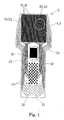
- the pressure-sensitive sensor S shown in Figs. 1 to 3 is one example of a multi-point sensor (a multi-point cell pattern). As shown in Figs. 1 and 2, the sensor S is formed in a manner that a constituent element S1 and a constituent element S2 are bonded together. As clearly shown in Fig. 2, the constituent element S1 is formed, by printing with silver, application-side electrodes 10, application-side terminals 11, and connecting wires 12 on a sheet base member 1, and further adding pressure-sensitive conductive ink 13 on each of the application-side electrodes 10 by printing.
- the constituent element S2 is formed, by printing with silver, receiving-side electrodes 20, receiving-side terminals 21, and connecting wires 22 on a sheet base member 2, and further adding pressure-sensitive conductive ink 23 on each of the receiving-side electrodes 20 by printing. Then, as shown in Fig. 3, the sheet base members 1 and 2 are integrated with each other with an adhesive agent or the like in a manner such that the application-side electrodes 10 and the receiving-side electrodes 20 perpendicularly cross each other and the pressure-sensitive conductive inks 13 and 23 oppose each other.
- the pressure-sensitive sensor has a thickness of about 0.1 mm and flexibility as a whole. Also, in this sensor, the application-side electrodes 10 are constituted in row electrodes, and the receiving-side electrodes 20 are constituted in column electrodes.
- a varnish A solution and a varnish B solution were prepared from two-liquid curing type silicone elastomer base solutions.
- the varnish A solution was prepared by dissolving 100 parts by weight of a base solution A (manufactured by Jujo Chemical Co., Ltd., trade name: JELCON-SRV-BR(A)) into 67 parts by weight of a solvent (manufactured by Kyowa Hakko Kogyo Co., Ltd., trade name: Butycell Acetate) by heating at 90°C.
- the varnish B solution was prepared by dissolving 100 parts by weight of a base solution B (manufactured by Jujo Chemical Co., Ltd., trade name: JELCON-SRV-TC(B)) into 67 parts by weight of a similar solvent (manufactured by Kyowa Hakko Kogyo Co., Ltd., trade name: Butycell Acetate) by heating at 90°C.
- a base solution B manufactured by Jujo Chemical Co., Ltd., trade name: JELCON-SRV-TC(B)
- a similar solvent manufactured by Kyowa Hakko Kogyo Co., Ltd., trade name: Butycell Acetate
- Equal parts by weight of the conductive ink A solution and the conductive ink B solution were mixed together to prepare an conductive ink mixture solution, and equal parts by weight of the insulating ink A solution and the Insulating ink B solution were mixed together to prepare an insulating ink mixture solution.
- the conductive ink mixture solution and the insulating ink mixture solution were blended together at a required ratio and stirred to prepare a pressure-sensitive conductive ink, and the resultant ink was applied onto the electrode pattern on the sheet base of a polyethylene naphthalate film.
- the screen-printed pressure-sensitive conductive ink was pre-cured for 4 minutes by a combination of hot air of 170°C and a far infrared furnace having a surface temperature of 220°C, and two or three more ink layers were added by printing. Subsequently, the ink was further cured for 8 minutes by a combination of hot air of 170°C and a far infrared furnace having a surface temperature of 220°C in the same manner as described above to obtain a pressure-sensitive sensor sample.
- the silicone elastomer obtained by mixing and thermally curing the conductive ink mixture solution and the insulating ink mixture solution has a glass transition temperature around -40°C. This applies also to the following Examples 2 and 3.
- the content of conductive carbon black differs depending on the resistance value of pressure-sensitive conductive ink.
- a range of 3 to 20 parts by weight of conductive carbon black is favorable, and further a range of 3 to 10 parts by weight is more favorable, Conductive carbon black having a primary particle size of 30 nm was used, but those having a primary particle size of about 20 to about 40 nm can be used similarly.
- silicone elastomer component With respect to 100 parts by weight of the silicone elastomer component, a range of 30 to 70 parts by weight of silicon dioxide is favorable, and a range of 40 to 60 parts by weight is more favorable. Silicon dioxide having a primary particle size of about 7 nm was used, but those having a primary particle size of about 7 to about 40 nm can be also used.
- a varnish A solution and a varnish B solution which made from two-liquid curing type silicone elastomer base solutions, were prepared in the same manner as in Example 1.
- Equal parts by weight of the conductive ink A solution and the conductive ink B solution were mixed together to prepare an conductive ink mixture solution, and equal parts by weight of the insulating ink A solution and the insulating ink B solution were mixed to prepare an insulating ink mixture solution.
- the conductive and the insulating ink mixture solutions were blended together at a required ratio and stirred to prepare a pressure-sensitive conductive ink, and the resultant ink was applied onto the electrode pattern on the sheet base of a polyethylene naphthalate film.
- the screen-printed pressure-sensitive conductive ink was cured in the same manner as in Example 1 to obtain a pressure-sensitive sensor sample.
- the content of conductive carbon black differs depending on the resistance value of pressure-sensitive conductive ink. With respect to 100 parts by weight of the silicone elastomer component, a range of 5 to 50 parts by weight of conductive carbon black is favorable, and further a range of 5 to 20 parts by weight is more favorable. Conductive carbon black having a primary particle size of 30 nm was used, but those having a primary particle size of about 20 to 40 nm can be also used.
- silicone elastomer component With respect to 100 parts by weight of the silicone elastomer component, a range of 30 to 70 parts by weight of silicon dioxide is favorable, and further a range of 40 to 60 parts by weight is more favorable. Silicon dioxide having a primary particle size of 7 nm was used, but those having a primary particle size of about 7 to about 40 nm can be also used.
- a varnish A solution and a varnish B solution which are made from two-liquid curing type silicone elastomer base solutions, were prepared in the same manner as in Example 1.
- Equal parts by weight of the conductive ink A solution and the conductive ink B solution were mixed together to prepare an conductive ink mixture solution, and equal parts by weight of the insulating ink A solution and the insulating ink B solution were mixed together to prepare an insulating ink mixture solution.
- the conductive and the insulating ink mixture solutions were blended together at a required ratio and stirred to prepare a pressure-sensitive conductive ink, and the resultant ink was applied onto the electrode pattern on the sheet base of a polyethylene naphthalate film.
- the screen-printed pressure-sensitive conductive ink was cured in the same manner as In Example 1 to obtain a pressure-sensitive sensor sample.
- the content of conductive carbon black differs depending on the resistance value of pressure-sensitive conductive ink and, with respect to 100 parts by weight of the silicone elastomer component, a range of 3 to 10 parts by weight of conductive carbon black is favorable.
- Conductive carbon black having a primary particle size of 30 nm was used, but those having a primary particle size of about 20 to about 40 nm can be also used.
- silicone elastomer component With respect to 100 parts by weight of the silicone elastomer component, a range of 30 to 70 parts by weight of silicon dioxide is favorable, and more favorably a range of 40 to 60 parts by weight. Silicon dioxide having a primary particle size of about 7 nm was used, but those having a primary particle size of about 7 to about 40 nm can be also used.
- pellet-shaped phenoxy resin manufactured by Toto Kasei Co., Ltd., trade name: Phenototo YP-50S
- conductive carbon black manufactured by Lion Corp., trade name: Ketjen Black EC600JD
- silicon dioxide manufactured by Japan Aerosyl Co., Ltd., trade name: Aerosyl R812
- a solvent manufactured by Kyowa Hakko Kogyo Co., Ltd., trade name: Butycell Acetate
- TDI adduct type polyisocyanate manufactured by Nippon Polyurethane Co., Ltd., trade name: Coronate L-70B
- Coronate L-70B Coronate L-70B
- a varnish A solution and a varnish B solution which are made from two-liquid curing type silicone elastomer base solutions, were prepared in the same manner as in Example 1, Using these varnish A and B solutions, an conductive ink A solution and an conductive ink B solution were prepared in the same manner as in Example 1.
- the varnish A solution and the varnish B solution were used as the insulating ink A solution and the insulating ink B solution, respectively.
- Equal parts by weight of the conductive ink A solution and the conductive ink B solution were mixed together to prepare an conductive ink mixture solution, and equal parts by weight of the insulating ink A solution and the insulating ink B solution were mixed together to prepare an insulating ink mixture solution.
- a pressure-sensitive conductive ink was prepared by stirring 40 parts by weight of the conductive ink mixture solution and 60 parts by weight of the insulating ink mixture solution, and applied onto an electrode pattern on a sheet base of a polyethylene naphthalate film.
- the screen-printed pressure-sensitive conductive ink was cured in the same manner as in Example 1 to obtain a pressure-sensitive sensor sample.
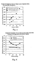
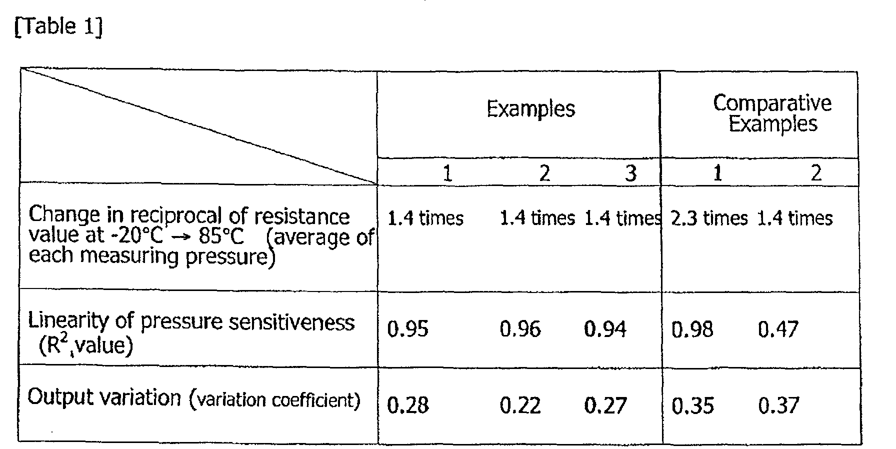
- the pressure-sensitive resistance value of a pressure-sensitive sensor having a single cell pattern (having a single pressure-sensitive element) was measured at temperatures of -20°C and 85°C under pressures of 10, 14, 16, 20, 30, and 40 kPa to evaluate change in the reciprocal of the resistance value by temperatures.
- the result of Example 1 is shown in Fig. 4, and that of Comparative Example 1 is shown in Fig. 5.
- Fig. 6 shows comparison between the results of Example 1 and Comparative Example 1.
- Examples 2, 3 and the comparative Example 2 the results of these tests are not shown in graphs.
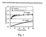
- the pressure-sensitive resistance value of a pressure-sensitive sensor having a single cell pattern (having a single pressure-sensitive element) was measured at room temperature (25°C) under pressures in the range from 4.9 to 98 kPa.
- the output average value was calculated from the total output values of the crossing positions on the row electrodes, the variation coefficient was calculated from the output standard deviation, and the output variation was evaluated.
- the pressure-sensitive sensor S using the pressure-sensitive conductive ink of Example 1 has an improved output stability and output irregularity at temperatures in a wide range from -20°C to a high temperature of 85°C, and also has a determining coefficient of linearity of pressure sensitiveness of output.
- Fig. 8 shows an exploded perspective view of a pressure-sensitive sensor S' according to the present invention, which has a single cell pattern, and this sensor S' is used in the evaluation test of temperature characteristics and the evaluation test of the linearity of pressure sensitiveness.
- the pressure-sensitive part of the sensor S' is shown in Fig. 9.
- this pressure-sensitive sensor S' is formed in a fashion that a constituent element S1' and a constituent element S2' are bonded together having a spacer 3 therebetween.
- the constituent element S1' was formed in a fashion that, on a sheet base member 1' of polyethylene naphthalate, application-side electrodes 10', application-side terminals 11' and connecting wires 12' were applied with a silver paste (manufactured by Acheson (Japan) Ltd., trade name: Electrodag PF-836) by pattern printing, followed by curing for 4 minutes using both hot air of 170°C and a far infrared furnace having a surface temperature of 220°C.
- the constituent element S2' was similarly formed with receiving-side electrodes 20', receiving-side terminals 21' and connecting wires 12'.
- pressure-sensitive ink prepared by blending and stirring an conductive Ink mixture solution and an insulating ink mixture solution at a suitable ratio in the same manner as in Example 1 was applied by screen printing, and was pre-cured for 4 minutes using both hot air of 170°C and a far infrared furnace having a surface temperature of 220°C. Another 2 or 3 layers of the ink were printed, and cured for 8 minutes at the temperatures similar to the above.
- the spacer 3 was constructed by applying a UV coating agent 30 (manufactured by Acheson (Japan) Ltd., trade name: UV-curing type insulating ink JE-1000G) on the sheet base members 1' and 2' so as to surround the pressure-sensitive conductive ink 13' and 23', which functions as a pressure-sensitive part, by screen printing, and curing the agent with UV radiation with an accumulated light quantity of 1000 mJ/cm 2 . Furthermore, on the printed and cured UV coating agent 30, an adhesive agent 31 (manufactured by Teikoku Printing Inks Mfg. Co., Ltd., trade name: CAT-1300S) was added by screen printing, and cured for 8 minutes with hot air of 120°C.
- a UV coating agent 30 manufactured by Acheson (Japan) Ltd., trade name: UV-curing type insulating ink JE-1000G
- an adhesive agent 31 manufactured by Teikoku Printing Inks Mfg. Co., Ltd., trade
- Example 4 a sensor sample of Example 4 was obtained by bonding the constituent element S1' and the constituent element S2' together through the adhesive agents 31 and 31.
- the sensor S' of Example 5 basically has the same form as the sensor S' of Example 4 except that the spacer 3 differs from that of Example 4, as shown in Fig. 10.
- the spacer 3 of Example 5 was formed as follows.
- An adhesive agent 32 (manufactured by Teikoku Printing Inks Mfg. Co., Ltd., trade name: CAT-13005) was applied on the sheet base members 1' and 2' of polyethylene naphthalate so as to surround the pressure-sensitive conductive ink 13' and 23', which functions as the pressure-sensitive part, shown as in Fig. 10, and cured for 8 minutes with hot air of 120°C.
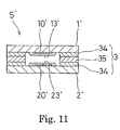
- the pressure-sensitive sensor S' of Example 6 basically has the same structure as that of Example 4 except that the spacer 3 differs from that of Example 4, as shown in Fig. 11.
- the spacer 3 of Example 6 was formed as follows.
- An adhesive agent 34 (manufactured by Teikoku Printing Inks Mfg. Co., Ltd., trade name: CAT-1300S) was applied on the sheet base members 1' and 2'of polyimide so as to surround the pressure-sensitive conductive ink 13' and 23', which is functions as the pressure-sensitive part, as shown in Fig. 11, and cured for 8 minutes with hot air of 120°C.
- a polyimide sheet 35 with a cut at the position corresponding to the pressure-sensitive conductive ink 13' and 23' part was bonded between the adhesive agents 34 and 34 on the sheet base members 1' and 2', and thereby a pressure-sensitive sensor sample was obtained.
- the pressure-sensitive resistance value of the pressure-sensitive sensor S' was measured at temperatures of -40°C and 85°C under pressures of 13, 20 and 40 kPa to evaluate change in the reciprocal of the resistance value by temperature.
- the results of Examples 4, 5 and 6 are shown in the graphs of Figs. 13, 15 and 17 respectively,
- the pressure-sensitive resistance value of the pressure-sensitive sensor S' was measured at room temperature (25°C) under pressures in a range of 0 to 100 kPa.
- the output average value was calculated from the total output values of the crossing positions on the row electrodes, and the variation coefficient was calculated from the output standard deviation to evaluate the output variation.
- the pressure-sensitive sensors S' of Examples 4, 5 and 6, which has the pressure-sensitive conductive ink of Example 1 and the spacer 3, have an improved output stability and an reduced output irregularity at temperatures in a wide range from -40°C to 85°C, and also have a determining coefficient of linearity of pressure sensitiveness of output.
Landscapes
- Physics & Mathematics (AREA)
- General Physics & Mathematics (AREA)
- Force Measurement Appropriate To Specific Purposes (AREA)
- Conductive Materials (AREA)
- Manufacture Of Switches (AREA)
- Measuring Fluid Pressure (AREA)
- Push-Button Switches (AREA)
- Investigating Or Analyzing Materials By The Use Of Fluid Adsorption Or Reactions (AREA)
Abstract
Description
| Examples | |||
| 4 | 5 | 6 | |
| Change in the reciprocal of resistance value at -40 → 85°C (average of each measuring pressure) | 1.42 times | 1.10 times | 1.04 times |
| Linearity of pressure sensitiveness (R2 value) | 0.94 | 0.94 | 0.95 |
| Output variation (variation coefficient) | 0.24 | 0.24 | 0.23 |
Claims (6)
- A pressure sensitive sensor comprising:in which resistance between the application-side electrode and the receiving-side electrode changes by a contact area between the conductive coatings on the electrodes; anda sheet base;an application-side and a receiving-side electrode provided on the sheet base;conductive coatings provided on the electrodes, the coating being provided with pressure-sensitive conductive ink containing conductive carbon black;
wherein the pressure-sensitive conductive ink has an enhanced strength as a resin and an enhanced effect of dispersion of the conductive carbon black by adding 30 to 70 parts by weight of silicon dioxide to 100 parts by weight of silicone elastomer component as a binder. - The pressure-sensitive sensor according to Claim 1, wherein the silicon dioxide has a primary particle size of 7 to 40 nm, the conductive carbon black has a primary particle size of 20 to 40 nm and is contained at 3 to 50 parts by weight with respect to 100 parts by weight of the silicone elastomer component.
- The pressure-sensitive sensor according to Claim 1 or 2, further comprising a multi-point pressure-sensitive part with 0.3 or less of variation coefficient of output.
- The pressure-sensitive sensor according to Claim 1 or 2, wherein the sheet base is formed with a pair of sheet base members of polyethylene naphthalate, one of the members being provided with the conductive coating covering the application-side electrode and another of the members being provided with the conductive coating covering the receiving-side electrode, wherein a spacer is provided between the sheet base members so as to surround the conductive coatings and obtain a space between the conductive coatings opposing each other at a no-load state, and the spacer is formed with a UV coating agent layer and an adhesive agent layer.
- The pressure-sensitive sensor according to Claim 1 or 2, wherein the sheet base is formed with a pair of sheet base members of polyethylene naphthalate, one of the members being provided with the conductive coating covering the application-side electrode and another of the members being provided with the conductive coating covering the receiving-side electrode, wherein a spacer is provided between the sheet base members so as to surround the conductive coatings and obtain a space between the conductive coatings opposing each other at a no-load state, and the spacer is formed a polyethylene naphthalate film and an adhesive agent layer.
- The pressure-sensitive sensor according to Claim 1 or 2, wherein the sheet base comprises a pair of sheet base members of polyimede, one of the members being provided with the conductive coating covering the application-side electrode and another of the members being provided with the conductive coating covering the receiving-side electrode, wherein a spacer is provided between the sheet base members so as to surround the conductive coatings and obtain a space between the conductive coatings opposing each other at a no-load state, and the space is formed a polyimede film and an adhesive agent layer.
Applications Claiming Priority (4)
| Application Number | Priority Date | Filing Date | Title |
|---|---|---|---|
| JP2003143604 | 2003-05-21 | ||
| JP2003143604 | 2003-05-21 | ||
| JP2004054562 | 2004-02-27 | ||
| JP2004054562 | 2004-02-27 |
Publications (3)
| Publication Number | Publication Date |
|---|---|
| EP1480029A2 true EP1480029A2 (en) | 2004-11-24 |
| EP1480029A3 EP1480029A3 (en) | 2005-11-09 |
| EP1480029B1 EP1480029B1 (en) | 2007-07-04 |
Family
ID=33100442
Family Applications (1)
| Application Number | Title | Priority Date | Filing Date |
|---|---|---|---|
| EP04253029A Expired - Lifetime EP1480029B1 (en) | 2003-05-21 | 2004-05-21 | Pressure-sensitive sensor |
Country Status (4)
| Country | Link |
|---|---|
| US (1) | US7112755B2 (en) |
| EP (1) | EP1480029B1 (en) |
| AT (1) | ATE366409T1 (en) |
| DE (1) | DE602004007322T2 (en) |
Cited By (12)
| Publication number | Priority date | Publication date | Assignee | Title |
|---|---|---|---|---|
| WO2014209818A1 (en) * | 2013-06-25 | 2014-12-31 | Microsoft Corporation | Pressure sensitive keys with a single-sided direct conduction sensor |
| EP2820520A4 (en) * | 2012-03-02 | 2015-12-30 | Microsoft Technology Licensing Llc | PRESSURE-SENSITIVE KEYS |
| US9678542B2 (en) | 2012-03-02 | 2017-06-13 | Microsoft Technology Licensing, Llc | Multiple position input device cover |
| US9793073B2 (en) | 2012-03-02 | 2017-10-17 | Microsoft Technology Licensing, Llc | Backlighting a fabric enclosure of a flexible cover |
| US9824808B2 (en) | 2012-08-20 | 2017-11-21 | Microsoft Technology Licensing, Llc | Switchable magnetic lock |
| US9870066B2 (en) | 2012-03-02 | 2018-01-16 | Microsoft Technology Licensing, Llc | Method of manufacturing an input device |
| EP2953012B1 (en) * | 2013-01-29 | 2018-04-18 | Suzhou Institute of Nano-tech and Nano-bionics (SINANO) Chinese Academy of Sciences | Electronic skin, preparation method and use thereof |
| US9959241B2 (en) | 2012-05-14 | 2018-05-01 | Microsoft Technology Licensing, Llc | System and method for accessory device architecture that passes via intermediate processor a descriptor when processing in a low power state |
| US10031556B2 (en) | 2012-06-08 | 2018-07-24 | Microsoft Technology Licensing, Llc | User experience adaptation |
| US10107994B2 (en) | 2012-06-12 | 2018-10-23 | Microsoft Technology Licensing, Llc | Wide field-of-view virtual image projector |
| US10156889B2 (en) | 2014-09-15 | 2018-12-18 | Microsoft Technology Licensing, Llc | Inductive peripheral retention device |
| USRE48963E1 (en) | 2012-03-02 | 2022-03-08 | Microsoft Technology Licensing, Llc | Connection device for computing devices |
Families Citing this family (52)
| Publication number | Priority date | Publication date | Assignee | Title |
|---|---|---|---|---|
| JP4496476B2 (en) * | 2005-02-23 | 2010-07-07 | 株式会社デンソー | Vehicle collision detection sensor and vehicle collision object discrimination device using the same |
| TWM291567U (en) * | 2005-12-23 | 2006-06-01 | Lite On Technology Corp | Membrane switch |
| US8181540B2 (en) | 2006-03-28 | 2012-05-22 | University Of Southern California | Measurement of sliding friction-induced vibrations for biomimetic tactile sensing |
| US7658119B2 (en) * | 2006-03-28 | 2010-02-09 | University Of Southern California | Biomimetic tactile sensor |
| US8049591B2 (en) * | 2006-08-31 | 2011-11-01 | Korea Research Institute Of Standards And Science | Tactile sensor for curved surface and manufacturing method thereof |
| US8272278B2 (en) * | 2007-03-28 | 2012-09-25 | University Of Southern California | Enhancements to improve the function of a biomimetic tactile sensor |
| US7528337B2 (en) * | 2007-05-15 | 2009-05-05 | Panasonic Corporation | Pressure sensitive conductive sheet and panel switch using same |
| EP2158454B1 (en) | 2007-05-18 | 2018-08-22 | University of Southern California | Biomimetic tactile sensor for control of grip |
| EP2006869A1 (en) * | 2007-06-22 | 2008-12-24 | IEE INTERNATIONAL ELECTRONICS & ENGINEERING S.A. | Film-type switching element |
| JP2011047893A (en) * | 2009-08-28 | 2011-03-10 | Nissha Printing Co Ltd | Pressure detection unit |
| TWI467601B (en) * | 2009-08-31 | 2015-01-01 | Universal Cement Corp | Micro-deformable piezo-resistive material and manufacturing method thereof |
| TWI407561B (en) * | 2009-11-10 | 2013-09-01 | Univ Nat Chiao Tung | Pressure detector and an array thereof |
| DE102011006448A1 (en) | 2010-03-31 | 2011-10-06 | Tk Holdings, Inc. | steering wheel sensors |
| US8587422B2 (en) | 2010-03-31 | 2013-11-19 | Tk Holdings, Inc. | Occupant sensing system |
| JP5759230B2 (en) | 2010-04-02 | 2015-08-05 | ティーケー ホールディングス,インコーポレーテッド | Steering wheel with hand sensor |
| US9298236B2 (en) | 2012-03-02 | 2016-03-29 | Microsoft Technology Licensing, Llc | Multi-stage power adapter configured to provide a first power level upon initial connection of the power adapter to the host device and a second power level thereafter upon notification from the host device to the power adapter |
| US9426905B2 (en) | 2012-03-02 | 2016-08-23 | Microsoft Technology Licensing, Llc | Connection device for computing devices |
| US9360893B2 (en) | 2012-03-02 | 2016-06-07 | Microsoft Technology Licensing, Llc | Input device writing surface |
| WO2013154720A1 (en) | 2012-04-13 | 2013-10-17 | Tk Holdings Inc. | Pressure sensor including a pressure sensitive material for use with control systems and methods of using the same |
| JP6260622B2 (en) | 2012-09-17 | 2018-01-17 | ティーケー ホールディングス インク.Tk Holdings Inc. | Single layer force sensor |
| US9304549B2 (en) | 2013-03-28 | 2016-04-05 | Microsoft Technology Licensing, Llc | Hinge mechanism for rotatable component attachment |
| KR102081892B1 (en) | 2013-09-05 | 2020-02-26 | 삼성전자주식회사 | Resistive pressure sensor including piezo-resistive electrode |
| JP2015088331A (en) * | 2013-10-30 | 2015-05-07 | パナソニックIpマネジメント株式会社 | Pressure-sensitive switch and manufacturing method thereof, touch panel including pressure-sensitive switch and manufacturing method thereof |
| JP2015088332A (en) * | 2013-10-30 | 2015-05-07 | パナソニックIpマネジメント株式会社 | Pressure-sensitive switch and manufacturing method thereof, touch panel including pressure-sensitive switch and manufacturing method thereof |
| US9421087B1 (en) | 2015-04-27 | 2016-08-23 | International Business Machines Corporation | Artificial electronic skin |
| US10466118B1 (en) | 2015-08-28 | 2019-11-05 | Multek Technologies, Ltd. | Stretchable flexible durable pressure sensor |
| KR101731173B1 (en) | 2015-09-02 | 2017-04-28 | 한국과학기술원 | Capacitive type pressure sensor with porous dielectric layer |
| US10054503B2 (en) | 2016-03-11 | 2018-08-21 | Microsoft Technology Licensing, Llc | Force sensor |
| JP6297613B2 (en) * | 2016-03-22 | 2018-03-20 | Nissha株式会社 | Pressure sensor |
| US10993635B1 (en) | 2016-03-22 | 2021-05-04 | Flextronics Ap, Llc | Integrating biosensor to compression shirt textile and interconnect method |
| US10418206B2 (en) * | 2016-09-10 | 2019-09-17 | Xiamen Pinnacle Electrical Co., Ltd. | Conducting structure and conducting method for upper sheet and lower sheet of film button circuit |
| US10888773B2 (en) * | 2016-10-11 | 2021-01-12 | Valve Corporation | Force sensing resistor (FSR) with polyimide substrate, systems, and methods thereof |
| US10898797B2 (en) | 2016-10-11 | 2021-01-26 | Valve Corporation | Electronic controller with finger sensing and an adjustable hand retainer |
| US11625898B2 (en) | 2016-10-11 | 2023-04-11 | Valve Corporation | Holding and releasing virtual objects |
| US10391400B1 (en) | 2016-10-11 | 2019-08-27 | Valve Corporation | Electronic controller with hand retainer and finger motion sensing |
| US10691233B2 (en) | 2016-10-11 | 2020-06-23 | Valve Corporation | Sensor fusion algorithms for a handheld controller that includes a force sensing resistor (FSR) |
| US11185763B2 (en) | 2016-10-11 | 2021-11-30 | Valve Corporation | Holding and releasing virtual objects |
| US10987573B2 (en) | 2016-10-11 | 2021-04-27 | Valve Corporation | Virtual reality hand gesture generation |
| US10307669B2 (en) | 2016-10-11 | 2019-06-04 | Valve Corporation | Electronic controller with finger sensing and an adjustable hand retainer |
| TWI627381B (en) * | 2016-10-21 | 2018-06-21 | 台灣艾華電子工業股份有限公司 | Bend sensor |
| JP2018077191A (en) * | 2016-11-11 | 2018-05-17 | 北川工業株式会社 | Pressure sensitive sensor |
| JP6770743B2 (en) | 2016-12-20 | 2020-10-21 | 北川工業株式会社 | Pressure sensor |
| KR102599441B1 (en) | 2017-06-16 | 2023-11-10 | 밸브 코포레이션 | Electronic controller with finger movement detection |
| CN107212505A (en) * | 2017-06-18 | 2017-09-29 | 王贺 | With footwear of the resistance with the pressure sensor of pressure change |
| US10444094B1 (en) * | 2017-07-14 | 2019-10-15 | Flex Ltd. | Bladder system for force sensitive resistors (FSR) sensors |
| US10690559B1 (en) | 2018-03-28 | 2020-06-23 | Flex Ltd. | Pressure sensor array and the method of making |
| US12279890B2 (en) | 2018-07-09 | 2025-04-22 | Takano Co., Ltd. | Pressure-sensitive sensor, mat system using pressure-sensitive sensor, and method for manufacturing pressure-sensitive sensor |
| US10650946B1 (en) | 2018-08-08 | 2020-05-12 | Flex Ltd. | Trimming method of DCR sensing circuits |
| US11022580B1 (en) | 2019-01-31 | 2021-06-01 | Flex Ltd. | Low impedance structure for PCB based electrodes |
| US11668686B1 (en) | 2019-06-17 | 2023-06-06 | Flex Ltd. | Batteryless architecture for color detection in smart labels |
| GB2588581B (en) * | 2019-10-14 | 2022-09-21 | Focusrite Audio Engineering Ltd | Button |
| EP3883040A1 (en) * | 2020-03-19 | 2021-09-22 | Hilti Aktiengesellschaft | Pouch cell arrangement |
Family Cites Families (9)
| Publication number | Priority date | Publication date | Assignee | Title |
|---|---|---|---|---|
| US3719913A (en) * | 1969-05-02 | 1973-03-06 | North American Rockwell | Viscous strain gage |
| US5068634A (en) * | 1988-01-11 | 1991-11-26 | Electromer Corporation | Overvoltage protection device and material |
| JPH01282802A (en) * | 1988-05-09 | 1989-11-14 | Toshiba Silicone Co Ltd | Pressure-sensitive resistance element |
| US4992333A (en) * | 1988-11-18 | 1991-02-12 | G&H Technology, Inc. | Electrical overstress pulse protection |
| DE3916921C1 (en) * | 1989-05-24 | 1990-10-11 | Preh-Werke Gmbh & Co Kg, 8740 Bad Neustadt, De | |
| US5260848A (en) * | 1990-07-27 | 1993-11-09 | Electromer Corporation | Foldback switching material and devices |
| JPH1078357A (en) * | 1996-09-04 | 1998-03-24 | Alps Electric Co Ltd | Pressure sensitive resistance element |
| JP3787717B2 (en) | 1999-12-28 | 2006-06-21 | ニッタ株式会社 | Pressure-sensitive conductive ink composition |
| DE10055082A1 (en) * | 2000-11-07 | 2002-05-16 | Bosch Gmbh Robert | Ceramic composite |
-
2004
- 2004-05-19 US US10/850,529 patent/US7112755B2/en not_active Expired - Fee Related
- 2004-05-21 EP EP04253029A patent/EP1480029B1/en not_active Expired - Lifetime
- 2004-05-21 AT AT04253029T patent/ATE366409T1/en not_active IP Right Cessation
- 2004-05-21 DE DE602004007322T patent/DE602004007322T2/en not_active Expired - Fee Related
Cited By (22)
| Publication number | Priority date | Publication date | Assignee | Title |
|---|---|---|---|---|
| US9852855B2 (en) | 2012-03-02 | 2017-12-26 | Microsoft Technology Licensing, Llc | Pressure sensitive key normalization |
| US9870066B2 (en) | 2012-03-02 | 2018-01-16 | Microsoft Technology Licensing, Llc | Method of manufacturing an input device |
| USRE48963E1 (en) | 2012-03-02 | 2022-03-08 | Microsoft Technology Licensing, Llc | Connection device for computing devices |
| US9618977B2 (en) | 2012-03-02 | 2017-04-11 | Microsoft Technology Licensing, Llc | Input device securing techniques |
| US9619071B2 (en) | 2012-03-02 | 2017-04-11 | Microsoft Technology Licensing, Llc | Computing device and an apparatus having sensors configured for measuring spatial information indicative of a position of the computing devices |
| US9678542B2 (en) | 2012-03-02 | 2017-06-13 | Microsoft Technology Licensing, Llc | Multiple position input device cover |
| US9710093B2 (en) | 2012-03-02 | 2017-07-18 | Microsoft Technology Licensing, Llc | Pressure sensitive key normalization |
| US9766663B2 (en) | 2012-03-02 | 2017-09-19 | Microsoft Technology Licensing, Llc | Hinge for component attachment |
| US9793073B2 (en) | 2012-03-02 | 2017-10-17 | Microsoft Technology Licensing, Llc | Backlighting a fabric enclosure of a flexible cover |
| US9904327B2 (en) | 2012-03-02 | 2018-02-27 | Microsoft Technology Licensing, Llc | Flexible hinge and removable attachment |
| EP2820520A4 (en) * | 2012-03-02 | 2015-12-30 | Microsoft Technology Licensing Llc | PRESSURE-SENSITIVE KEYS |
| US10963087B2 (en) | 2012-03-02 | 2021-03-30 | Microsoft Technology Licensing, Llc | Pressure sensitive keys |
| US10013030B2 (en) | 2012-03-02 | 2018-07-03 | Microsoft Technology Licensing, Llc | Multiple position input device cover |
| US9946307B2 (en) | 2012-03-02 | 2018-04-17 | Microsoft Technology Licensing, Llc | Classifying the intent of user input |
| US9959241B2 (en) | 2012-05-14 | 2018-05-01 | Microsoft Technology Licensing, Llc | System and method for accessory device architecture that passes via intermediate processor a descriptor when processing in a low power state |
| US10031556B2 (en) | 2012-06-08 | 2018-07-24 | Microsoft Technology Licensing, Llc | User experience adaptation |
| US10107994B2 (en) | 2012-06-12 | 2018-10-23 | Microsoft Technology Licensing, Llc | Wide field-of-view virtual image projector |
| US9824808B2 (en) | 2012-08-20 | 2017-11-21 | Microsoft Technology Licensing, Llc | Switchable magnetic lock |
| EP2953012B1 (en) * | 2013-01-29 | 2018-04-18 | Suzhou Institute of Nano-tech and Nano-bionics (SINANO) Chinese Academy of Sciences | Electronic skin, preparation method and use thereof |
| WO2014209818A1 (en) * | 2013-06-25 | 2014-12-31 | Microsoft Corporation | Pressure sensitive keys with a single-sided direct conduction sensor |
| CN105393098A (en) * | 2013-06-25 | 2016-03-09 | 微软技术许可有限责任公司 | Pressure sensitive keys with a single-sided direct conduction sensor |
| US10156889B2 (en) | 2014-09-15 | 2018-12-18 | Microsoft Technology Licensing, Llc | Inductive peripheral retention device |
Also Published As
| Publication number | Publication date |
|---|---|
| DE602004007322T2 (en) | 2008-03-06 |
| EP1480029A3 (en) | 2005-11-09 |
| US20040231969A1 (en) | 2004-11-25 |
| ATE366409T1 (en) | 2007-07-15 |
| US7112755B2 (en) | 2006-09-26 |
| EP1480029B1 (en) | 2007-07-04 |
| DE602004007322D1 (en) | 2007-08-16 |
| HK1070130A1 (en) | 2005-06-10 |
Similar Documents
| Publication | Publication Date | Title |
|---|---|---|
| EP1480029B1 (en) | Pressure-sensitive sensor | |
| EP2154503B1 (en) | Capacitive deformation sensor | |
| KR101439718B1 (en) | Transparent force sensor and method of fabrication | |
| US7068142B2 (en) | Pressure-sensitive resistor and pressure-sensitive sensor using the same | |
| JP3882172B2 (en) | Pressure sensor | |
| CN102165298B (en) | Pressure sensor | |
| EP2131269A1 (en) | Protective panel with touch input function of electronic instrument display window | |
| US8213175B2 (en) | Electronic device having improved input device | |
| JPH1078357A (en) | Pressure sensitive resistance element | |
| JPH01282802A (en) | Pressure-sensitive resistance element | |
| JP3787717B2 (en) | Pressure-sensitive conductive ink composition | |
| US20130264179A1 (en) | Touch panel | |
| JP2003280800A (en) | Touch panel | |
| US5997996A (en) | Sheet-like pressure-sensitive resistance member having electrodes, method of making the same, and sheet-like pressure-sensitive resistance member | |
| JPH05143219A (en) | Transparent input panel | |
| CZ180295A3 (en) | Power sensor | |
| HK1070130B (en) | Pressure-sensitive sensor | |
| JP2000348564A (en) | Pressure-sensitive device | |
| JP2003139630A (en) | Film-shaped pressure-sensitive resistor and pressure-sensitive sensor | |
| US20260119028A1 (en) | Handwriting elimination apparatus and method for touch screen, electronic stylus pen, and pen cap thereof | |
| JP2008070938A (en) | Touch panel | |
| JPS5933072Y2 (en) | input device | |
| JPS6022568Y2 (en) | pressure sensitive electric element | |
| CN121160008A (en) | Pressure-sensitive composition, pressure-sensitive film layer and pressure-sensitive structure | |
| JPS5849605Y2 (en) | pressure sensitive electric element |
Legal Events
| Date | Code | Title | Description |
|---|---|---|---|
| PUAI | Public reference made under article 153(3) epc to a published international application that has entered the european phase |
Free format text: ORIGINAL CODE: 0009012 |
|
| AK | Designated contracting states |
Kind code of ref document: A2 Designated state(s): AT BE BG CH CY CZ DE DK EE ES FI FR GB GR HU IE IT LI LU MC NL PL PT RO SE SI SK TR |
|
| AX | Request for extension of the european patent |
Extension state: AL HR LT LV MK |
|
| REG | Reference to a national code |
Ref country code: HK Ref legal event code: DE Ref document number: 1070130 Country of ref document: HK |
|
| PUAL | Search report despatched |
Free format text: ORIGINAL CODE: 0009013 |
|
| AK | Designated contracting states |
Kind code of ref document: A3 Designated state(s): AT BE BG CH CY CZ DE DK EE ES FI FR GB GR HU IE IT LI LU MC NL PL PT RO SE SI SK TR |
|
| AX | Request for extension of the european patent |
Extension state: AL HR LT LV MK |
|
| RIC1 | Information provided on ipc code assigned before grant |
Ipc: 7C 09D 11/00 B Ipc: 7G 01L 1/20 A |
|
| 17P | Request for examination filed |
Effective date: 20060307 |
|
| AKX | Designation fees paid |
Designated state(s): AT BE BG CH CY CZ DE DK EE ES FI FR GB GR HU IE IT LI LU MC NL PL PT RO SE SI SK TR |
|
| AXX | Extension fees paid |
Extension state: AL Payment date: 20050513 Extension state: LV Payment date: 20050513 Extension state: MK Payment date: 20050513 Extension state: HR Payment date: 20050513 Extension state: LT Payment date: 20050513 |
|
| GRAP | Despatch of communication of intention to grant a patent |
Free format text: ORIGINAL CODE: EPIDOSNIGR1 |
|
| R17C | First examination report despatched (corrected) |
Effective date: 20060420 |
|
| GRAS | Grant fee paid |
Free format text: ORIGINAL CODE: EPIDOSNIGR3 |
|
| GRAA | (expected) grant |
Free format text: ORIGINAL CODE: 0009210 |
|
| AK | Designated contracting states |
Kind code of ref document: B1 Designated state(s): AT BE BG CH CY CZ DE DK EE ES FI FR GB GR HU IE IT LI LU MC NL PL PT RO SE SI SK TR |
|
| AX | Request for extension of the european patent |
Extension state: AL HR LT LV MK |
|
| REG | Reference to a national code |
Ref country code: GB Ref legal event code: FG4D |
|
| REG | Reference to a national code |
Ref country code: CH Ref legal event code: EP |
|
| REG | Reference to a national code |
Ref country code: IE Ref legal event code: FG4D |
|
| REF | Corresponds to: |
Ref document number: 602004007322 Country of ref document: DE Date of ref document: 20070816 Kind code of ref document: P |
|
| REG | Reference to a national code |
Ref country code: HK Ref legal event code: GR Ref document number: 1070130 Country of ref document: HK |
|
| LTIE | Lt: invalidation of european patent or patent extension |
Effective date: 20070704 |
|
| ET | Fr: translation filed | ||
| NLV1 | Nl: lapsed or annulled due to failure to fulfill the requirements of art. 29p and 29m of the patents act | ||
| REG | Reference to a national code |
Ref country code: CH Ref legal event code: PL |
|
| PG25 | Lapsed in a contracting state [announced via postgrant information from national office to epo] |
Ref country code: FI Free format text: LAPSE BECAUSE OF FAILURE TO SUBMIT A TRANSLATION OF THE DESCRIPTION OR TO PAY THE FEE WITHIN THE PRESCRIBED TIME-LIMIT Effective date: 20070704 Ref country code: BG Free format text: LAPSE BECAUSE OF FAILURE TO SUBMIT A TRANSLATION OF THE DESCRIPTION OR TO PAY THE FEE WITHIN THE PRESCRIBED TIME-LIMIT Effective date: 20071004 Ref country code: SI Free format text: LAPSE BECAUSE OF FAILURE TO SUBMIT A TRANSLATION OF THE DESCRIPTION OR TO PAY THE FEE WITHIN THE PRESCRIBED TIME-LIMIT Effective date: 20070704 Ref country code: ES Free format text: LAPSE BECAUSE OF FAILURE TO SUBMIT A TRANSLATION OF THE DESCRIPTION OR TO PAY THE FEE WITHIN THE PRESCRIBED TIME-LIMIT Effective date: 20071015 Ref country code: PT Free format text: LAPSE BECAUSE OF FAILURE TO SUBMIT A TRANSLATION OF THE DESCRIPTION OR TO PAY THE FEE WITHIN THE PRESCRIBED TIME-LIMIT Effective date: 20071204 Ref country code: NL Free format text: LAPSE BECAUSE OF FAILURE TO SUBMIT A TRANSLATION OF THE DESCRIPTION OR TO PAY THE FEE WITHIN THE PRESCRIBED TIME-LIMIT Effective date: 20070704 |
|
| PG25 | Lapsed in a contracting state [announced via postgrant information from national office to epo] |
Ref country code: PL Free format text: LAPSE BECAUSE OF FAILURE TO SUBMIT A TRANSLATION OF THE DESCRIPTION OR TO PAY THE FEE WITHIN THE PRESCRIBED TIME-LIMIT Effective date: 20070704 Ref country code: CH Free format text: LAPSE BECAUSE OF FAILURE TO SUBMIT A TRANSLATION OF THE DESCRIPTION OR TO PAY THE FEE WITHIN THE PRESCRIBED TIME-LIMIT Effective date: 20070704 Ref country code: LI Free format text: LAPSE BECAUSE OF FAILURE TO SUBMIT A TRANSLATION OF THE DESCRIPTION OR TO PAY THE FEE WITHIN THE PRESCRIBED TIME-LIMIT Effective date: 20070704 Ref country code: AT Free format text: LAPSE BECAUSE OF FAILURE TO SUBMIT A TRANSLATION OF THE DESCRIPTION OR TO PAY THE FEE WITHIN THE PRESCRIBED TIME-LIMIT Effective date: 20070704 |
|
| PG25 | Lapsed in a contracting state [announced via postgrant information from national office to epo] |
Ref country code: BE Free format text: LAPSE BECAUSE OF FAILURE TO SUBMIT A TRANSLATION OF THE DESCRIPTION OR TO PAY THE FEE WITHIN THE PRESCRIBED TIME-LIMIT Effective date: 20070704 |
|
| PG25 | Lapsed in a contracting state [announced via postgrant information from national office to epo] |
Ref country code: GR Free format text: LAPSE BECAUSE OF FAILURE TO SUBMIT A TRANSLATION OF THE DESCRIPTION OR TO PAY THE FEE WITHIN THE PRESCRIBED TIME-LIMIT Effective date: 20071005 Ref country code: DK Free format text: LAPSE BECAUSE OF FAILURE TO SUBMIT A TRANSLATION OF THE DESCRIPTION OR TO PAY THE FEE WITHIN THE PRESCRIBED TIME-LIMIT Effective date: 20070704 |
|
| PLBE | No opposition filed within time limit |
Free format text: ORIGINAL CODE: 0009261 |
|
| STAA | Information on the status of an ep patent application or granted ep patent |
Free format text: STATUS: NO OPPOSITION FILED WITHIN TIME LIMIT |
|
| PG25 | Lapsed in a contracting state [announced via postgrant information from national office to epo] |
Ref country code: SK Free format text: LAPSE BECAUSE OF FAILURE TO SUBMIT A TRANSLATION OF THE DESCRIPTION OR TO PAY THE FEE WITHIN THE PRESCRIBED TIME-LIMIT Effective date: 20070704 Ref country code: CZ Free format text: LAPSE BECAUSE OF FAILURE TO SUBMIT A TRANSLATION OF THE DESCRIPTION OR TO PAY THE FEE WITHIN THE PRESCRIBED TIME-LIMIT Effective date: 20070704 |
|
| 26N | No opposition filed |
Effective date: 20080407 |
|
| PG25 | Lapsed in a contracting state [announced via postgrant information from national office to epo] |
Ref country code: SE Free format text: LAPSE BECAUSE OF FAILURE TO SUBMIT A TRANSLATION OF THE DESCRIPTION OR TO PAY THE FEE WITHIN THE PRESCRIBED TIME-LIMIT Effective date: 20071004 Ref country code: RO Free format text: LAPSE BECAUSE OF FAILURE TO SUBMIT A TRANSLATION OF THE DESCRIPTION OR TO PAY THE FEE WITHIN THE PRESCRIBED TIME-LIMIT Effective date: 20070704 |
|
| PGFP | Annual fee paid to national office [announced via postgrant information from national office to epo] |
Ref country code: DE Payment date: 20080523 Year of fee payment: 5 |
|
| PG25 | Lapsed in a contracting state [announced via postgrant information from national office to epo] |
Ref country code: MC Free format text: LAPSE BECAUSE OF NON-PAYMENT OF DUE FEES Effective date: 20080531 |
|
| PGFP | Annual fee paid to national office [announced via postgrant information from national office to epo] |
Ref country code: GB Payment date: 20080520 Year of fee payment: 5 |
|
| PG25 | Lapsed in a contracting state [announced via postgrant information from national office to epo] |
Ref country code: EE Free format text: LAPSE BECAUSE OF FAILURE TO SUBMIT A TRANSLATION OF THE DESCRIPTION OR TO PAY THE FEE WITHIN THE PRESCRIBED TIME-LIMIT Effective date: 20070704 Ref country code: IE Free format text: LAPSE BECAUSE OF NON-PAYMENT OF DUE FEES Effective date: 20080521 |
|
| PG25 | Lapsed in a contracting state [announced via postgrant information from national office to epo] |
Ref country code: CY Free format text: LAPSE BECAUSE OF FAILURE TO SUBMIT A TRANSLATION OF THE DESCRIPTION OR TO PAY THE FEE WITHIN THE PRESCRIBED TIME-LIMIT Effective date: 20070704 |
|
| GBPC | Gb: european patent ceased through non-payment of renewal fee |
Effective date: 20090521 |
|
| REG | Reference to a national code |
Ref country code: FR Ref legal event code: ST Effective date: 20100129 |
|
| PG25 | Lapsed in a contracting state [announced via postgrant information from national office to epo] |
Ref country code: FR Free format text: LAPSE BECAUSE OF NON-PAYMENT OF DUE FEES Effective date: 20090602 |
|
| PG25 | Lapsed in a contracting state [announced via postgrant information from national office to epo] |
Ref country code: GB Free format text: LAPSE BECAUSE OF NON-PAYMENT OF DUE FEES Effective date: 20090521 |
|
| PG25 | Lapsed in a contracting state [announced via postgrant information from national office to epo] |
Ref country code: DE Free format text: LAPSE BECAUSE OF NON-PAYMENT OF DUE FEES Effective date: 20091201 |
|
| PG25 | Lapsed in a contracting state [announced via postgrant information from national office to epo] |
Ref country code: LU Free format text: LAPSE BECAUSE OF NON-PAYMENT OF DUE FEES Effective date: 20080521 Ref country code: HU Free format text: LAPSE BECAUSE OF FAILURE TO SUBMIT A TRANSLATION OF THE DESCRIPTION OR TO PAY THE FEE WITHIN THE PRESCRIBED TIME-LIMIT Effective date: 20080105 |
|
| PG25 | Lapsed in a contracting state [announced via postgrant information from national office to epo] |
Ref country code: TR Free format text: LAPSE BECAUSE OF FAILURE TO SUBMIT A TRANSLATION OF THE DESCRIPTION OR TO PAY THE FEE WITHIN THE PRESCRIBED TIME-LIMIT Effective date: 20070704 |
|
| PG25 | Lapsed in a contracting state [announced via postgrant information from national office to epo] |
Ref country code: IT Free format text: LAPSE BECAUSE OF NON-PAYMENT OF DUE FEES Effective date: 20080531 |
|
| PGFP | Annual fee paid to national office [announced via postgrant information from national office to epo] |
Ref country code: FR Payment date: 20080521 Year of fee payment: 5 |