EP1479968A2 - Post mount for outdoor cantilevered lighting fixtures - Google Patents
Post mount for outdoor cantilevered lighting fixtures Download PDFInfo
- Publication number
- EP1479968A2 EP1479968A2 EP04002047A EP04002047A EP1479968A2 EP 1479968 A2 EP1479968 A2 EP 1479968A2 EP 04002047 A EP04002047 A EP 04002047A EP 04002047 A EP04002047 A EP 04002047A EP 1479968 A2 EP1479968 A2 EP 1479968A2
- Authority
- EP
- European Patent Office
- Prior art keywords
- post
- mount according
- extruded
- mount
- lighting fixture
- Prior art date
- Legal status (The legal status is an assumption and is not a legal conclusion. Google has not performed a legal analysis and makes no representation as to the accuracy of the status listed.)
- Withdrawn
Links
Images




Classifications
-
- F—MECHANICAL ENGINEERING; LIGHTING; HEATING; WEAPONS; BLASTING
- F21—LIGHTING
- F21S—NON-PORTABLE LIGHTING DEVICES; SYSTEMS THEREOF; VEHICLE LIGHTING DEVICES SPECIALLY ADAPTED FOR VEHICLE EXTERIORS
- F21S8/00—Lighting devices intended for fixed installation
- F21S8/08—Lighting devices intended for fixed installation with a standard
- F21S8/081—Lighting devices intended for fixed installation with a standard of low-built type, e.g. landscape light
-
- E—FIXED CONSTRUCTIONS
- E04—BUILDING
- E04H—BUILDINGS OR LIKE STRUCTURES FOR PARTICULAR PURPOSES; SWIMMING OR SPLASH BATHS OR POOLS; MASTS; FENCING; TENTS OR CANOPIES, IN GENERAL
- E04H12/00—Towers; Masts or poles; Chimney stacks; Water-towers; Methods of erecting such structures
- E04H12/02—Structures made of specified materials
- E04H12/08—Structures made of specified materials of metal
-
- F—MECHANICAL ENGINEERING; LIGHTING; HEATING; WEAPONS; BLASTING
- F21—LIGHTING
- F21S—NON-PORTABLE LIGHTING DEVICES; SYSTEMS THEREOF; VEHICLE LIGHTING DEVICES SPECIALLY ADAPTED FOR VEHICLE EXTERIORS
- F21S8/00—Lighting devices intended for fixed installation
- F21S8/08—Lighting devices intended for fixed installation with a standard
- F21S8/085—Lighting devices intended for fixed installation with a standard of high-built type, e.g. street light
- F21S8/086—Lighting devices intended for fixed installation with a standard of high-built type, e.g. street light with lighting device attached sideways of the standard, e.g. for roads and highways
-
- F—MECHANICAL ENGINEERING; LIGHTING; HEATING; WEAPONS; BLASTING
- F21—LIGHTING
- F21V—FUNCTIONAL FEATURES OR DETAILS OF LIGHTING DEVICES OR SYSTEMS THEREOF; STRUCTURAL COMBINATIONS OF LIGHTING DEVICES WITH OTHER ARTICLES, NOT OTHERWISE PROVIDED FOR
- F21V21/00—Supporting, suspending, or attaching arrangements for lighting devices; Hand grips
- F21V21/10—Pendants, arms, or standards; Fixing lighting devices to pendants, arms, or standards
- F21V21/116—Fixing lighting devices to arms or standards
-
- F—MECHANICAL ENGINEERING; LIGHTING; HEATING; WEAPONS; BLASTING
- F21—LIGHTING
- F21V—FUNCTIONAL FEATURES OR DETAILS OF LIGHTING DEVICES OR SYSTEMS THEREOF; STRUCTURAL COMBINATIONS OF LIGHTING DEVICES WITH OTHER ARTICLES, NOT OTHERWISE PROVIDED FOR
- F21V21/00—Supporting, suspending, or attaching arrangements for lighting devices; Hand grips
- F21V21/34—Supporting elements displaceable along a guiding element
Definitions
- the present invention relates to a post mount for outdoor cantilevered lighting fixtures.
- the field of application of the post mount for lighting fixtures relates to outdoor lighting systems for squares, streets, sidewalks and urban furnishings in general and for gardens, driveways and residential furnishings in general.
- the lamps are fixed to the posts by means of clamps, straps, collars et cetera.
- Another commonly used system is to fix the lamps to the posts by means of holes already provided in the posts by the post manufacturer.
- a third system that is known in the art comprises fixing the luminaires to the posts by means of holes provided in the posts during installation.
- Fixing the lamps to the posts by means of clamps, terminals or straps is rather unbecoming from the aesthetic standpoint, because the styling of the post is not integrated with the styling of the lamp and there is also the limitation that it is not possible to position a plurality of lighting fixtures on the same level or at the same distance from the ground.
- Holes in the posts are particularly inconvenient if they are produced by the installer or end user, since they force him or her to perform additional work with difficult fixing operations.
- the placement of the lamps on the posts is fixed and not adjustable.
- An aim of the present invention is to provide a mount that overcomes the drawbacks of the cited prior art.
- An object of the invention is to provide a mount that allows to concile the styling with installation functionality and flexibility, allowing to decide the placement of the lighting fixture on the post at the time of installation.
- a further object of the invention is to provide a mount that allows to eliminate the need to supply posts that are preset for mounting the luminaires in different positions.
- a further object is to provide a mount in which the post can be positioned in the holes in the ground regardless of the installation elevation with respect to the ground of the lamps that can be applied, since the fixtures are mounted in a subsequent step at the user's discretion.
- a further object is to provide a mount that allows quick installation, since the system for fixing the arm of the lamps to the post by insertion and locking with screws does not require work on the post.
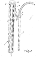
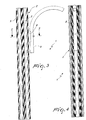
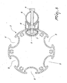
- a mount according to the invention generally designated by the reference numeral 1, comprises a post 2 that is preferably made of extruded aluminum and has semicircular grooves 5 provided along its entire length.
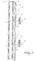
- a block 3 preferably made of pressure die-cast aluminum or zinc-aluminum-magnesium alloy and provided with threaded holes 4, can be applied to the grooves 5 and acts as a supporting member for a lighting fixture.
- the curved tube 8 has an inlet 10 for an electric power supply cable 11 and acts as a member for mutually anchoring the lighting fixture 12 and the post 2.
- the lighting fixture 12 is applied to the free end of the curved tube 8, and the power supply cable 11 passes from the base of the extruded post into the curved tube and then reaches the lighting fixture.
- the extruded post 2 is fixed in the ground by burying it, for example for approximately 50 centimeters, cementing it in the appropriately provided hole or by fitting the extruded post over a previously anchored 60-mm tube.
- each lighting fixture is supported by means of two blocks, as in the illustrated examples.
- a first spacer 6 is fixed by means of a screw 13 to the upper block 3 and then the same operation is repeated for the pair constituted by the lower block and spacer.
- the center distances can be defined by a template or by a measurement.
- the curved tube 8 is positioned on the upper spacer and fixed by means of the screw 9. The operation is repeated in the lower part and the power supply cable 11 is inserted in the groove of the extruded post 2 and is made to rise up to the top 22 thereof, where it accesses the internal protected part of the post through an opening provided on the cap 23 of the post.
- the cable descends again inside the post to connect to the junction box in the installation hole.
- a snap-on cable housing 24 that conceals the power supply cable is fastened to the outside of the groove of the extruded post.
- the base 14 of the lighting fixture 12 is fitted onto the curved end of the curved tube 8 and electrical connection to the lighting fixture is thus provided.
- the mount according to the invention is conceived for mounting lighting fixtures with a tube that is curved upward or downward and for providing maximum installation flexibility by making the installation independent of preset heights.
- the compositions of the lighting fixtures on the post also are at the user's discretion.
- a further advantage of the invention is that the composition of the lamps on the posts in terms of number and quantity and type is decided after inserting the post in the ground and can be increased at a later time on the remaining free grooves.
- the materials used, as well as the dimensions, may of course be any according to requirements and to the state of the art.
Landscapes
- Engineering & Computer Science (AREA)
- General Engineering & Computer Science (AREA)
- Architecture (AREA)
- Life Sciences & Earth Sciences (AREA)
- Chemical & Material Sciences (AREA)
- Materials Engineering (AREA)
- Wood Science & Technology (AREA)
- Civil Engineering (AREA)
- Structural Engineering (AREA)
- Fastening Of Light Sources Or Lamp Holders (AREA)
- Non-Portable Lighting Devices Or Systems Thereof (AREA)
Abstract
Description
Claims (8)
- A post mount for outdoor cantilevered lighting fixtures, characterized in that it comprises a post provided with one or more substantially vertical grooves in which one or more fixing means for fixing lighting fixtures or other items are associated at a chosen height.
- The mount according to claim 1, characterized in that said post is an extruded aluminum post provided with semicircular grooves formed along its entire length.
- The mount according to claim 1 or 2, characterized in that said fixing means comprises a block made of pressure die-cast aluminum or zing-aluminum-magnesium alloy, provided with threaded holes and suitable to be applied to said grooves in order to constitute a member for supporting a lighting fixture.
- The mount according to one or more of the preceding claims, characterized in that it comprises an extruded or pressure die-cast aluminum spacer, provided with holes for the insertion of screws and shaped so as to accommodate a curved tube provided with at least one hole for a fixing screw.
- The mount according to one or more of the preceding claims, characterized in that said curved tube has an inlet for an electric power supply cable and acts as a member for mutually anchoring the lighting fixture and said post.
- The mount according to one or more of the preceding claims, characterized in that said lighting fixture is applied to the free end of said curved tube and the power supply cable passes from the base of the extruded post into the curved tube and then reaches the lighting fixture.
- The mount according to one or more of the preceding claims, characterized in that the power supply cable is inserted in the groove of the extruded post and is made to rise to the top of said post where it accesses the internal protected part of the post through an opening provided on a cap of the post; the cable then descends again inside the post to connect to the junction box in the installation hole.
- The mount according to one or more of the preceding claims, characterized in that it comprises a snap-on cable housing that is fastened to the outside of the groove of the extruded post in order to conceal the power supply cable.
Applications Claiming Priority (2)
| Application Number | Priority Date | Filing Date | Title |
|---|---|---|---|
| IT000990A ITMI20030990A1 (en) | 2003-05-20 | 2003-05-20 | POLE FIXING STRUCTURE FOR OUTDOOR LIGHTING LUMINAIRES ON ARM. |
| ITMI20030990 | 2003-05-20 |
Publications (2)
| Publication Number | Publication Date |
|---|---|
| EP1479968A2 true EP1479968A2 (en) | 2004-11-24 |
| EP1479968A3 EP1479968A3 (en) | 2005-09-14 |
Family
ID=33042701
Family Applications (1)
| Application Number | Title | Priority Date | Filing Date |
|---|---|---|---|
| EP04002047A Withdrawn EP1479968A3 (en) | 2003-05-20 | 2004-01-30 | Post mount for outdoor cantilevered lighting fixtures |
Country Status (2)
| Country | Link |
|---|---|
| EP (1) | EP1479968A3 (en) |
| IT (1) | ITMI20030990A1 (en) |
Cited By (4)
| Publication number | Priority date | Publication date | Assignee | Title |
|---|---|---|---|---|
| DE102005044259A1 (en) * | 2005-09-15 | 2007-03-29 | Semperlux Ag - Lichttechnische Werke - | light tower |
| WO2009066065A3 (en) * | 2007-11-24 | 2009-07-16 | Varley And Gulliver Ltd | Structural support |
| WO2009092286A1 (en) * | 2008-01-15 | 2009-07-30 | The Hong Kong Polytechnic University | Led lamp head |
| RU2853704C1 (en) * | 2025-05-02 | 2025-12-25 | Общество с ограниченной ответственностью "Трисити" | Smart support |
Family Cites Families (6)
| Publication number | Priority date | Publication date | Assignee | Title |
|---|---|---|---|---|
| US3086627A (en) * | 1958-05-10 | 1963-04-23 | Frank J Bernard | Means for supporting panels, bars, rods and the like |
| IT206748Z2 (en) * | 1986-01-28 | 1987-10-01 | Aluminia Spa | MULTIFUNCTIONAL EXTRUDED ALUMINUM PROFILE, ITS ALLOYS AND SIMILAR, CONSTITUTING A MODULAR ELEMENT PARTICULARLY SUITABLE FOR URBAN FURNITURE. |
| ATE247253T1 (en) * | 1995-06-20 | 2003-08-15 | Siteco Beleuchtungstech Gmbh | EXTENSION ARM FOR AN OUTDOOR LAMP |
| SG75798A1 (en) * | 1996-06-22 | 2000-10-24 | Aluminium Structure Pte Ltd | A fencing system |
| DE29913138U1 (en) * | 1999-07-27 | 1999-09-23 | Czaja, Marian, 99326 Stadtilm | Pole bow for street lights |
| GB2354779A (en) * | 1999-09-30 | 2001-04-04 | Simmonsigns Ltd | A post for an illuminated sign or lamp |
-
2003
- 2003-05-20 IT IT000990A patent/ITMI20030990A1/en unknown
-
2004
- 2004-01-30 EP EP04002047A patent/EP1479968A3/en not_active Withdrawn
Cited By (7)
| Publication number | Priority date | Publication date | Assignee | Title |
|---|---|---|---|---|
| DE102005044259A1 (en) * | 2005-09-15 | 2007-03-29 | Semperlux Ag - Lichttechnische Werke - | light tower |
| EP1764545A3 (en) * | 2005-09-15 | 2007-12-05 | Semperlux Aktiengesellschaft, Lichttechnische Werke | Lamppost |
| DE102005044259B4 (en) * | 2005-09-15 | 2008-01-10 | Semperlux Ag - Lichttechnische Werke - | light tower |
| WO2009066065A3 (en) * | 2007-11-24 | 2009-07-16 | Varley And Gulliver Ltd | Structural support |
| US8434731B2 (en) | 2007-11-24 | 2013-05-07 | Varley And Gulliver Limited | Structural support |
| WO2009092286A1 (en) * | 2008-01-15 | 2009-07-30 | The Hong Kong Polytechnic University | Led lamp head |
| RU2853704C1 (en) * | 2025-05-02 | 2025-12-25 | Общество с ограниченной ответственностью "Трисити" | Smart support |
Also Published As
| Publication number | Publication date |
|---|---|
| ITMI20030990A1 (en) | 2004-11-21 |
| EP1479968A3 (en) | 2005-09-14 |
Similar Documents
| Publication | Publication Date | Title |
|---|---|---|
| US6503099B2 (en) | Quick connect device for electrical fixture | |
| US6799982B2 (en) | Quick connect device for electrical fixture | |
| CN110692286B (en) | Parts kit, modular housing, street pole and installation method | |
| CN110953518A (en) | Modular combined outdoor lighting equipment and installation method thereof | |
| US6293510B1 (en) | Luminaire mounting bracket | |
| WO1998056995A1 (en) | Improved in-ground lighting apparatus and related method | |
| US20030209356A1 (en) | Pedestal for outdoor circuits | |
| AU660517B2 (en) | Device for lighting and suspension of a hanging-rod and modular assembly for lighting and suspension of hanging-rods | |
| US7261445B2 (en) | Lighting kit | |
| KR101668056B1 (en) | Base block for installing the street light posts | |
| KR100366710B1 (en) | Flagpole support | |
| US6834983B1 (en) | Combination lighting fixture with swivel and mounting post | |
| US7547122B1 (en) | Area security light with adaptable mounting hardware | |
| EP0645579A1 (en) | Illuminating device for illuminating park or public square | |
| KR200333042Y1 (en) | race way with lighting fixture | |
| KR200452654Y1 (en) | Security light holder | |
| EP4413294B1 (en) | Crossarm retrofit system | |
| KR200346285Y1 (en) | Stand light have concents | |
| KR200211860Y1 (en) | Flagpole support | |
| KR0131295Y1 (en) | Form for street lamp poles | |
| KR200347517Y1 (en) | Fluorescent lamp supporting eguippment with electric wire fixture | |
| HU215006B (en) | Lamppost | |
| CN118176386A (en) | Cross arm modification system | |
| US3067325A (en) | Street and sidewalk lighting means | |
| KR100889349B1 (en) | Luminaire mounting device |
Legal Events
| Date | Code | Title | Description |
|---|---|---|---|
| PUAI | Public reference made under article 153(3) epc to a published international application that has entered the european phase |
Free format text: ORIGINAL CODE: 0009012 |
|
| AK | Designated contracting states |
Kind code of ref document: A2 Designated state(s): AT BE BG CH CY CZ DE DK EE ES FI FR GB GR HU IE IT LI LU MC NL PT RO SE SI SK TR |
|
| AX | Request for extension of the european patent |
Extension state: AL LT LV MK |
|
| PUAL | Search report despatched |
Free format text: ORIGINAL CODE: 0009013 |
|
| AK | Designated contracting states |
Kind code of ref document: A3 Designated state(s): AT BE BG CH CY CZ DE DK EE ES FI FR GB GR HU IE IT LI LU MC NL PT RO SE SI SK TR |
|
| AX | Request for extension of the european patent |
Extension state: AL LT LV MK |
|
| AKX | Designation fees paid | ||
| REG | Reference to a national code |
Ref country code: DE Ref legal event code: 8566 |
|
| STAA | Information on the status of an ep patent application or granted ep patent |
Free format text: STATUS: THE APPLICATION IS DEEMED TO BE WITHDRAWN |
|
| 18D | Application deemed to be withdrawn |
Effective date: 20060315 |