EP1479872A1 - Thread integrity feature for expandable connections - Google Patents
Thread integrity feature for expandable connections Download PDFInfo
- Publication number
- EP1479872A1 EP1479872A1 EP04076499A EP04076499A EP1479872A1 EP 1479872 A1 EP1479872 A1 EP 1479872A1 EP 04076499 A EP04076499 A EP 04076499A EP 04076499 A EP04076499 A EP 04076499A EP 1479872 A1 EP1479872 A1 EP 1479872A1
- Authority
- EP
- European Patent Office
- Prior art keywords
- tubular
- threaded section
- connection
- pin member
- box member
- Prior art date
- Legal status (The legal status is an assumption and is not a legal conclusion. Google has not performed a legal analysis and makes no representation as to the accuracy of the status listed.)
- Granted
Links
- 238000000034 method Methods 0.000 claims description 16
- 239000000565 sealant Substances 0.000 claims description 4
- 238000007789 sealing Methods 0.000 description 10
- 239000000463 material Substances 0.000 description 5
- 239000004809 Teflon Substances 0.000 description 3
- 229920006362 Teflon® Polymers 0.000 description 3
- 230000015572 biosynthetic process Effects 0.000 description 3
- 238000005755 formation reaction Methods 0.000 description 3
- 230000008569 process Effects 0.000 description 3
- 230000000694 effects Effects 0.000 description 2
- 230000009467 reduction Effects 0.000 description 2
- 230000008859 change Effects 0.000 description 1
- 230000008878 coupling Effects 0.000 description 1
- 238000010168 coupling process Methods 0.000 description 1
- 238000005859 coupling reaction Methods 0.000 description 1
- 238000005553 drilling Methods 0.000 description 1
- 229930195733 hydrocarbon Natural products 0.000 description 1
- 150000002430 hydrocarbons Chemical class 0.000 description 1
- 230000007246 mechanism Effects 0.000 description 1
- 239000004033 plastic Substances 0.000 description 1
- 238000003825 pressing Methods 0.000 description 1
- 239000007787 solid Substances 0.000 description 1
Images


Classifications
-
- E—FIXED CONSTRUCTIONS
- E21—EARTH OR ROCK DRILLING; MINING
- E21B—EARTH OR ROCK DRILLING; OBTAINING OIL, GAS, WATER, SOLUBLE OR MELTABLE MATERIALS OR A SLURRY OF MINERALS FROM WELLS
- E21B43/00—Methods or apparatus for obtaining oil, gas, water, soluble or meltable materials or a slurry of minerals from wells
- E21B43/02—Subsoil filtering
- E21B43/10—Setting of casings, screens, liners or the like in wells
- E21B43/103—Setting of casings, screens, liners or the like in wells of expandable casings, screens, liners, or the like
- E21B43/106—Couplings or joints therefor
-
- E—FIXED CONSTRUCTIONS
- E21—EARTH OR ROCK DRILLING; MINING
- E21B—EARTH OR ROCK DRILLING; OBTAINING OIL, GAS, WATER, SOLUBLE OR MELTABLE MATERIALS OR A SLURRY OF MINERALS FROM WELLS
- E21B17/00—Drilling rods or pipes; Flexible drill strings; Kellies; Drill collars; Sucker rods; Cables; Casings; Tubings
- E21B17/02—Couplings; joints
- E21B17/08—Casing joints
-
- E—FIXED CONSTRUCTIONS
- E21—EARTH OR ROCK DRILLING; MINING
- E21B—EARTH OR ROCK DRILLING; OBTAINING OIL, GAS, WATER, SOLUBLE OR MELTABLE MATERIALS OR A SLURRY OF MINERALS FROM WELLS
- E21B43/00—Methods or apparatus for obtaining oil, gas, water, soluble or meltable materials or a slurry of minerals from wells
- E21B43/02—Subsoil filtering
- E21B43/10—Setting of casings, screens, liners or the like in wells
- E21B43/103—Setting of casings, screens, liners or the like in wells of expandable casings, screens, liners, or the like
Definitions
- Embodiments of the present invention generally relate to wellbore completion, and more particularly, to tubular connections.
- threaded connections are used to connect multiple tubular members end-to-end. This is usually accomplished by providing tubulars that have a simple male to female threaded connection.
- the male end is generally referred to as a pin, and the female end as a box.
- the tubulars are connected, or "made-up,” by transmitting torque against one of the tubulars while the other tubular is typically held stationary. Torque is transmitted in a single direction in accordance with the direction corresponding with connection make-up. Any torque applied to the joint in the make-up direction will have the effect of continuing to tighten the threaded joint.
- the most basic type of expander tool employs a simple cone-shaped body, which is typically run into a wellbore at the bottom of the casing that is to be expanded. The expander tool is then forced upward in the wellbore by both pulling on the working string from the surface and applying pressure below the cone.
- a basic arrangement of a conical expander tool is disclosed in U.S. Patent 5,348,095, issued to Worrall, et al., and that patent is incorporated herein in its entirety. Pulling the expanded conical tool has the effect of expanding a portion of a tubular into sealed engagement with a surrounding formation wall, thereby sealing off the annular region therebetween.
- Rotary expander tools employ one or more rows of compliant rollers that are urged outwardly from a body of the expander tool in order to engage and to expand the surrounding tubular.
- the expander tool is rotated downhole so that the actuated rollers can act against the inner surface of the tubular to be expanded in order to expand the tubular body circumferentially.
- Radial expander tools are described in U.S. Patent 6,457,532, issued to Simpson et al., and that patent is incorporated herein by reference in its entirety.
- Tubulars to be later expanded are typically run downhole where the mechanical and seal integrity of the connections or joints are critically important both in the original and expanded state of the tubulars.
- the current method of making-up expandable tubulars uses threaded connections that can be applied and handled in the same way as conventional oil-field tubulars, i.e., stabbed into each other and screwed together by right hand or left hand rotation and finally torqued to establish the seal integrity.
- This method of connecting tubulars though a reliable means of connecting non-expanding tubulars, is proving to be problematic when these tubulars are expanded. The reasons for this being mainly due to the changes in geometry of the connection during expansion due to the stresses applied at the threads or joint area. For instance, conventional tubulars expanded at the joint may disengage, allowing the lower tubing to fall into the wellbore.
- Embodiments of the present invention are generally directed to a wellbore expandable connection, which includes a tubular pin member having an outwardly facing tapered threaded section and a tubular box member having an inwardly facing tapered threaded section.
- the threaded sections form a connection of a predetermined integrity when the tubular pin member is mated with the tubular box member. The integrity of the connection is substantially maintained during radial expansion of the connection.
- the wall thickness of the pin member along a substantial portion of the outwardly facing threaded section is substantially constant.
- the wall thickness of the box member along a substantial portion of the inwardly facing threaded section is substantially constant.
- Figure 1 is an elevation view schematically showing tubulars within a borehole and a representative expander tool at a joint between two tubulars.
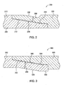
- FIG. 2 illustrates a threaded connection in greater details in accordance with one embodiment of the invention.
- FIG. 3 illustrates a threaded connection in accordance with another embodiment of the invention.
- Figure 4 illustrates a threaded connection in accordance with yet another embodiment of the invention.
- Figure 1 illustrates an embodiment of the present invention in use within a wellbore 10. Visible in Figure 1 is a representative rig 2, a ground surface 6, a formation 4, a drill string or running string 8, a first tubular 101, a second tubular 201, a representative expander tool 40 comprising a body 42 and an expansion member 45 or roller, a bore 400 running through the tubulars, and a connection 60 or joint, between the first tubular 101 and the second tubular 201.
- first tubular 101 and the second tubular 201 are mated together at the surface 6 according to normal stab-in and threading procedures.
- the stab-in procedures can be preformed with tubulars arranged in a pin up and a box down configuration or a configuration with the pin down and the box up.
- the tubulars can be expanded from within by any method known to those skilled in the art.
- the expansion process can be run in any axial and/or rotational direction within the tubulars 101, 201. As shown, a running tool with an expander tool 40 attached thereto is run up the bore 400 of the tubulars. At a desired location, an operator expands the tubulars.
- connection 60 between the first tubular 101 and the second tubular 201 When the expander tool 40 reaches the connection 60 between the first tubular 101 and the second tubular 201, an internal wall of the pin portion of the second tubular 201 expands into an internal wall of the box portion of the first tubular 101.
- the connection 60 between the tubulars 101, 201 is capable of being expanded without losing its mechanical or sealing integrity.
- FIG. 2 illustrates a threaded connection 200 in greater details in accordance with one embodiment of the invention.
- the connection 200 includes a pin member 210 formed at a threaded section of the first tubular 101 and a box member 220 formed at a threaded section of the second tubular 201.
- the threaded sections of the pin member 210 and the box member 220 are tapered.
- the pin member 210 includes helical threads 212 extending along its length.
- the box member 220 includes helical threads 224 that are shaped and sized to mate with the helical threads 212 during the make-up of the threaded connection. 200.
- the threaded sections of the pin member 210 and the box member 220 form the connection 200 of a predetermined integrity when the pin member 210 is mated with the box member 220.
- the threads may be coated with Teflon, an inert sealant, or other material known to those in the art for sealing purposes.
- the threads may be dovetail threads, as described in U.S. Patent No. 3,989,284, issued to Blose, and that patent is incorporated herein by reference.
- the threads may be machined on plain end tubulars, tubulars with both ends upset, tubulars with one plain end and one end upset, or other connection types as typically used in the oil and gas industry.
- One of ordinary skill in the art can appreciate that embodiments of the present invention are not limited to only certain kinds of tubular ends or thread types.
- the box member 220 is constructed such that the wall thickness 250 of the box member 220 along a substantial portion of the threaded section is substantially constant, thereby allowing the threaded section of the box member 220 to bend in parallel with the threaded section of the pin member 210 during expansion.
- the outer surface 230 of the box member 220 along the threaded section may be substantially in parallel with the inner surface 235 of the box member 220 along the threaded section and the outside diameter of the box member 220 along the threaded section may be less than the outside diameter of the box member 220 along the non-threaded section.
- the connection 200 is capable of being radially expanded without substantially losing its mechanical or sealing integrity.
- FIG. 3 illustrates a threaded connection 300 in accordance with another embodiment of the invention.
- the connection 300 includes a pin member 310 formed at a threaded section of the first tubular 101 and a box member 320 formed at a threaded section of the second tubular 201.
- the threaded sections of the pin member 310 and the box member 320 are tapered.
- the pin member 310 includes helical threads 312 extending along its length.
- the box member 320 includes helical threads 324 that are shaped and sized to mate with the helical threads 312 during the make-up of the threaded connection 300.
- the threaded sections of the pin member 310 and the box member 320 form the connection 300 of a predetermined integrity when the pin member 310 is mated with the box member 320.
- the threads may be coated with Teflon, an inert sealant, or other material known to those in the art for sealing purposes.
- the threads may be dovetail threads, as described in U.S. Patent No. 3,989,284, issued to Blose, and that patent is incorporated herein by reference.
- the threads may be machined on plain end tubulars, tubulars with both ends upset, tubulars with one plain end and one end upset, or other connection types as typically used in the oil and gas industry.
- One of ordinary skill in the art can appreciate that embodiments of the present invention are not limited to only certain kinds of tubular ends or thread types.
- the pin member 310 is constructed such that the wall thickness 350 of the pin member 310 along a substantial portion of the threaded section is substantially constant, thereby allowing the threaded section of the pin member 310 to bend in parallel with the threaded section of the box member 320 during expansion.
- the outer surface 335 of the pin member 310 along the threaded section may be substantially in parallel with the inner surface 330 of the pin member 310 along the threaded section and the inside diameter of the pin member 310 along the threaded section may be less than the inside diameter of the pin member 310 along the non-threaded section. In this manner, the connection 300 is capable of being radially expanded without substantially losing its mechanical or sealing integrity.
- FIG. 4 illustrates a threaded connection 400 in accordance with yet another embodiment of the invention.
- the connection 400 includes a pin member 410 formed at a threaded section of the first tubular 101 and a box member 420 formed at a threaded section of the second tubular 201.
- the threaded sections of the pin member 410 and the box member 420 are tapered.
- the pin member 410 includes helical threads 412 extending along its length.
- the box member 420 includes helical threads 424 that are shaped and sized to mate with the helical threads 412 during the make-up of the threaded connection 400.
- the threaded sections of the pin member 410 and the box member 420 form the connection 400 of a predetermined integrity when the pin member 410 is mated with the box member 420.
- the threads may be coated with Teflon, an inert sealant, or other material known to those in the art for sealing purposes.
- the threads may be dovetail threads, as described in U.S. Patent No. 3,989,284, issued to Blose, and that patent is incorporated herein by reference.
- the threads may be machined on plain end tubulars, tubulars with both ends upset, tubulars with one plain end and one end upset, or other connection types as typically used in the oil and gas industry.
- One of ordinary skill in the art can appreciate that embodiments of the present invention are not limited to only certain kinds of tubular ends or thread types.
- the pin member 410 is constructed such that the wall thickness 450 of the pin member 410 along a substantial portion of the threaded section is substantially constant. As such, the outer surface 435 of the pin member 410 along the threaded section may be substantially in parallel with the inner surface 430 of the pin member 410 along the threaded section and the inside diameter of the pin member 410 along the threaded section may be less than the inside diameter of the pin member 410 along the non-threaded section.
- the box member 420 is constructed such that the wall thickness 451 of the box member 420 along a substantial portion of the threaded section is substantially constant. As such, the outer surface 431 of the box member 420 along the threaded section may be substantially in parallel with the inner surface 436 of the box member 420 along the threaded section and the outside diameter of the box member 420 along the threaded section may be less than the outside diameter of the box member 420 along the non-threaded section. In this manner, the connection 400 is capable of being expanded without substantially losing its mechanical or sealing integrity.
- embodiments of the invention are described with reference to a box member, other types of tubular resembling a box member, such as a coupling, are also contemplated by the embodiments of the invention.
Landscapes
- Engineering & Computer Science (AREA)
- Life Sciences & Earth Sciences (AREA)
- Geology (AREA)
- Mining & Mineral Resources (AREA)
- Physics & Mathematics (AREA)
- Environmental & Geological Engineering (AREA)
- Fluid Mechanics (AREA)
- General Life Sciences & Earth Sciences (AREA)
- Geochemistry & Mineralogy (AREA)
- Mechanical Engineering (AREA)
- Earth Drilling (AREA)
- Non-Disconnectible Joints And Screw-Threaded Joints (AREA)
Abstract
Description
- Embodiments of the present invention generally relate to wellbore completion, and more particularly, to tubular connections.
- In order to access hydrocarbons in subsurface formations, it is typically necessary to drill a bore into the earth. The process of drilling a borehole and of subsequently completing the borehole in order to form a wellbore requires the use of various tubular strings. These tubulars are typically run downhole where the mechanical and seal integrity of the jointed connections are critically important in the original make-up of the tubulars, during expansion of the tubulars, and after expansion of the tubulars.
- Typically threaded connections are used to connect multiple tubular members end-to-end. This is usually accomplished by providing tubulars that have a simple male to female threaded connection. The male end is generally referred to as a pin, and the female end as a box. The tubulars are connected, or "made-up," by transmitting torque against one of the tubulars while the other tubular is typically held stationary. Torque is transmitted in a single direction in accordance with the direction corresponding with connection make-up. Any torque applied to the joint in the make-up direction will have the effect of continuing to tighten the threaded joint.
- When running tubulars, there is sometimes a requirement to run jointed tubulars that will later be expanded by various types of expansion mechanisms. The most basic type of expander tool employs a simple cone-shaped body, which is typically run into a wellbore at the bottom of the casing that is to be expanded. The expander tool is then forced upward in the wellbore by both pulling on the working string from the surface and applying pressure below the cone. A basic arrangement of a conical expander tool is disclosed in U.S. Patent 5,348,095, issued to Worrall, et al., and that patent is incorporated herein in its entirety. Pulling the expanded conical tool has the effect of expanding a portion of a tubular into sealed engagement with a surrounding formation wall, thereby sealing off the annular region therebetween. More recently, rotary expander tools have been developed. Rotary expander tools employ one or more rows of compliant rollers that are urged outwardly from a body of the expander tool in order to engage and to expand the surrounding tubular. The expander tool is rotated downhole so that the actuated rollers can act against the inner surface of the tubular to be expanded in order to expand the tubular body circumferentially. Radial expander tools are described in U.S. Patent 6,457,532, issued to Simpson et al., and that patent is incorporated herein by reference in its entirety.
- Tubulars to be later expanded are typically run downhole where the mechanical and seal integrity of the connections or joints are critically important both in the original and expanded state of the tubulars. The current method of making-up expandable tubulars uses threaded connections that can be applied and handled in the same way as conventional oil-field tubulars, i.e., stabbed into each other and screwed together by right hand or left hand rotation and finally torqued to establish the seal integrity. This method of connecting tubulars, though a reliable means of connecting non-expanding tubulars, is proving to be problematic when these tubulars are expanded. The reasons for this being mainly due to the changes in geometry of the connection during expansion due to the stresses applied at the threads or joint area. For instance, conventional tubulars expanded at the joint may disengage, allowing the lower tubing to fall into the wellbore.
- It is well known and understood that during the expansion of solid wall tubulars, the material in the tubing wall is plastically deformed in more than just the circumferential sense. In order for a tubular to increase in diameter by plastic deformation, the material to make-up the additional circumferential section of wall in the larger diameter must come from the tubing wall itself either by reduction in wall thickness or by reduction in tubular length or a combination of both. In a plain wall section of the tubular this process will normally take place in a relatively controlled and uniform way. However, at the point of a threaded connection, the changes in wall section, such as that of the box or pin, introduce very complex and non-uniform stresses during and after expansion. These during-expansion stresses may significantly change the thread form and compromise the connection integrity both in terms of its mechanical strength as well as in terms of its sealing capability.
- Therefore, a need exists for an improved tubular connection that is capable of being expanded without losing its mechanical or sealing integrity.
- Embodiments of the present invention are generally directed to a wellbore expandable connection, which includes a tubular pin member having an outwardly facing tapered threaded section and a tubular box member having an inwardly facing tapered threaded section. The threaded sections form a connection of a predetermined integrity when the tubular pin member is mated with the tubular box member. The integrity of the connection is substantially maintained during radial expansion of the connection.
- In one embodiment, the wall thickness of the pin member along a substantial portion of the outwardly facing threaded section is substantially constant.
- In another embodiment, the wall thickness of the box member along a substantial portion of the inwardly facing threaded section is substantially constant.
- So that the manner in which the above recited features of the present invention can be understood in detail, a more particular description of the invention, briefly summarized above, may be had by reference to embodiments, some of which are illustrated in the appended drawings. It is to be noted, however, that the appended drawings illustrate only typical embodiments of this invention and are therefore not to be considered limiting of its scope, for the invention may admit to other equally effective embodiments.
- Figure 1 is an elevation view schematically showing tubulars within a borehole and a representative expander tool at a joint between two tubulars.
- Figure 2 illustrates a threaded connection in greater details in accordance with one embodiment of the invention.
- Figure 3 illustrates a threaded connection in accordance with another embodiment of the invention.
- Figure 4 illustrates a threaded connection in accordance with yet another embodiment of the invention.
- Figure 1 illustrates an embodiment of the present invention in use within a
wellbore 10. Visible in Figure 1 is arepresentative rig 2, aground surface 6, aformation 4, a drill string or runningstring 8, a first tubular 101, a second tubular 201, arepresentative expander tool 40 comprising abody 42 and anexpansion member 45 or roller, abore 400 running through the tubulars, and aconnection 60 or joint, between the first tubular 101 and thesecond tubular 201. - In operation, the first tubular 101 and the
second tubular 201 are mated together at thesurface 6 according to normal stab-in and threading procedures. The stab-in procedures can be preformed with tubulars arranged in a pin up and a box down configuration or a configuration with the pin down and the box up. After run-in, the tubulars can be expanded from within by any method known to those skilled in the art. The expansion process can be run in any axial and/or rotational direction within thetubulars expander tool 40 attached thereto is run up thebore 400 of the tubulars. At a desired location, an operator expands the tubulars. When theexpander tool 40 reaches theconnection 60 between thefirst tubular 101 and thesecond tubular 201, an internal wall of the pin portion of thesecond tubular 201 expands into an internal wall of the box portion of thefirst tubular 101. Theconnection 60 between thetubulars - Figure 2 illustrates a threaded
connection 200 in greater details in accordance with one embodiment of the invention. Theconnection 200 includes apin member 210 formed at a threaded section of the first tubular 101 and abox member 220 formed at a threaded section of thesecond tubular 201. In one embodiment, the threaded sections of thepin member 210 and thebox member 220 are tapered. Thepin member 210 includeshelical threads 212 extending along its length. Thebox member 220 includeshelical threads 224 that are shaped and sized to mate with thehelical threads 212 during the make-up of the threaded connection. 200. The threaded sections of thepin member 210 and thebox member 220 form theconnection 200 of a predetermined integrity when thepin member 210 is mated with thebox member 220. Additionally, depending upon wellbore characteristics, the threads may be coated with Teflon, an inert sealant, or other material known to those in the art for sealing purposes. The threads may be dovetail threads, as described in U.S. Patent No. 3,989,284, issued to Blose, and that patent is incorporated herein by reference. The threads may be machined on plain end tubulars, tubulars with both ends upset, tubulars with one plain end and one end upset, or other connection types as typically used in the oil and gas industry. One of ordinary skill in the art can appreciate that embodiments of the present invention are not limited to only certain kinds of tubular ends or thread types. - In one embodiment, the
box member 220 is constructed such that thewall thickness 250 of thebox member 220 along a substantial portion of the threaded section is substantially constant, thereby allowing the threaded section of thebox member 220 to bend in parallel with the threaded section of thepin member 210 during expansion. As such, theouter surface 230 of thebox member 220 along the threaded section may be substantially in parallel with theinner surface 235 of thebox member 220 along the threaded section and the outside diameter of thebox member 220 along the threaded section may be less than the outside diameter of thebox member 220 along the non-threaded section. In this manner, theconnection 200 is capable of being radially expanded without substantially losing its mechanical or sealing integrity. - Figure 3 illustrates a threaded
connection 300 in accordance with another embodiment of the invention. Theconnection 300 includes apin member 310 formed at a threaded section of thefirst tubular 101 and abox member 320 formed at a threaded section of thesecond tubular 201. In one embodiment, the threaded sections of thepin member 310 and thebox member 320 are tapered. Thepin member 310 includeshelical threads 312 extending along its length. Thebox member 320 includeshelical threads 324 that are shaped and sized to mate with thehelical threads 312 during the make-up of the threadedconnection 300. The threaded sections of thepin member 310 and thebox member 320 form theconnection 300 of a predetermined integrity when thepin member 310 is mated with thebox member 320. Additionally, depending upon wellbore characteristics, the threads may be coated with Teflon, an inert sealant, or other material known to those in the art for sealing purposes. The threads may be dovetail threads, as described in U.S. Patent No. 3,989,284, issued to Blose, and that patent is incorporated herein by reference. The threads may be machined on plain end tubulars, tubulars with both ends upset, tubulars with one plain end and one end upset, or other connection types as typically used in the oil and gas industry. One of ordinary skill in the art can appreciate that embodiments of the present invention are not limited to only certain kinds of tubular ends or thread types. - The
pin member 310 is constructed such that thewall thickness 350 of thepin member 310 along a substantial portion of the threaded section is substantially constant, thereby allowing the threaded section of thepin member 310 to bend in parallel with the threaded section of thebox member 320 during expansion. As such, theouter surface 335 of thepin member 310 along the threaded section may be substantially in parallel with theinner surface 330 of thepin member 310 along the threaded section and the inside diameter of thepin member 310 along the threaded section may be less than the inside diameter of thepin member 310 along the non-threaded section. In this manner, theconnection 300 is capable of being radially expanded without substantially losing its mechanical or sealing integrity. - Figure 4 illustrates a threaded
connection 400 in accordance with yet another embodiment of the invention. Theconnection 400 includes apin member 410 formed at a threaded section of thefirst tubular 101 and abox member 420 formed at a threaded section of thesecond tubular 201. In one embodiment, the threaded sections of thepin member 410 and thebox member 420 are tapered. Thepin member 410 includeshelical threads 412 extending along its length. Thebox member 420 includeshelical threads 424 that are shaped and sized to mate with thehelical threads 412 during the make-up of the threadedconnection 400. The threaded sections of thepin member 410 and thebox member 420 form theconnection 400 of a predetermined integrity when thepin member 410 is mated with thebox member 420. Additionally, depending upon wellbore characteristics, the threads may be coated with Teflon, an inert sealant, or other material known to those in the art for sealing purposes. The threads may be dovetail threads, as described in U.S. Patent No. 3,989,284, issued to Blose, and that patent is incorporated herein by reference. The threads may be machined on plain end tubulars, tubulars with both ends upset, tubulars with one plain end and one end upset, or other connection types as typically used in the oil and gas industry. One of ordinary skill in the art can appreciate that embodiments of the present invention are not limited to only certain kinds of tubular ends or thread types. - The
pin member 410 is constructed such that thewall thickness 450 of thepin member 410 along a substantial portion of the threaded section is substantially constant. As such, theouter surface 435 of thepin member 410 along the threaded section may be substantially in parallel with theinner surface 430 of thepin member 410 along the threaded section and the inside diameter of thepin member 410 along the threaded section may be less than the inside diameter of thepin member 410 along the non-threaded section. - The
box member 420 is constructed such that thewall thickness 451 of thebox member 420 along a substantial portion of the threaded section is substantially constant. As such, theouter surface 431 of thebox member 420 along the threaded section may be substantially in parallel with theinner surface 436 of thebox member 420 along the threaded section and the outside diameter of thebox member 420 along the threaded section may be less than the outside diameter of thebox member 420 along the non-threaded section. In this manner, theconnection 400 is capable of being expanded without substantially losing its mechanical or sealing integrity. Although embodiments of the invention are described with reference to a box member, other types of tubular resembling a box member, such as a coupling, are also contemplated by the embodiments of the invention. - While the foregoing is directed to embodiments of the present invention, other and further embodiments of the invention may be devised without departing from the basic scope thereof, and the scope thereof is determined by the claims that follow.
Claims (20)
- A wellbore expandable connection, comprising:a tubular pin member having an outwardly facing tapered threaded section; anda tubular box member having an inwardly facing tapered threaded section, wherein the threaded sections form a connection of a predetermined integrity when the tubular pin member is mated with the tubular box member, and wherein the integrity of the connection is substantially maintained during radial expansion of the connection.
- The connection of claim 1, wherein the connection defines an interface that is not parallel to a longitudinal axis of one of the tubular pin member and the tubular box member.
- The connection of claim 1, wherein a wall thickness of the tubular box member along a substantial portion of the tapered threaded section is substantially constant.
- The connection of claim 1, wherein an outside diameter of the tubular box member opposite at least a portion of the inwardly facing tapered threaded section is less than an outside diameter of the tubular box member opposite a non-threaded section of the tubular box member.
- The connection of claim 1, wherein an outer surface of the tubular box member is substantially parallel with an inner surface of the tubular box member along a substantial portion of the tapered threaded section.
- The connection of claim 1, wherein a wall thickness of the tubular pin member along a substantial portion of the tapered threaded section is substantially constant.
- The connection of claim 1, wherein an inside diameter of the tubular pin member opposite at least a portion of the outwardly facing tapered threaded section is less than an inside diameter of the tubular pin member opposite a non-threaded section of the tubular pin member.
- The connection of claim 1, wherein an outer surface of the tubular pin member is substantially parallel with an inner surface of the tubular pin member along a substantial portion of the tapered threaded section.
- The connection of claim 1, wherein each tapered threaded section comprises a plurality of threads coated with a sealant.
- A method for utilizing an expandable connection in a wellbore, comprising:running an assembly on a tubular string into the wellbore, the assembly comprising:a tubular pin member having an outwardly facing tapered threaded section; anda tubular box member having an inwardly facing tapered threaded section, wherein the threaded sections form a connection of a predetermined integrity when the tubular pin member is mated with the tubular box member, and wherein the integrity of the connection is substantially maintained during radial expansion of the connection; andexpanding the assembly radially outward.
- The connection of claim 10, wherein a wall thickness of the tubular box member along a substantial portion of the tapered threaded section is substantially constant.
- The method of claim 10, wherein an outside diameter of the tubular box member opposite at least a portion of the inwardly facing tapered threaded section is less than an outside diameter of the tubular box member opposite a non-threaded section of the tubular box member.
- The method of claim 10, wherein an outer surface of the tubular box member is substantially parallel with an inner surface of the tubular box member along a substantial portion of the tapered threaded section.
- The method of claim 10, wherein expanding the assembly comprises expanding at least a portion of the connection.
- The method of claim 10, wherein expanding the assembly comprises expanding the tapered threaded sections of the tubular pin member and the tubular box member.
- The method of claim 10, wherein a wall thickness of the tubular pin member along a substantial portion of the tapered threaded section is substantially constant.
- The method of claim 10, wherein an inside diameter of the tubular pin member opposite at least a portion of the outwardly facing tapered threaded section is less than an inside diameter of the tubular pin member opposite a non-threaded section of the tubular pin member.
- The method of claim 10, wherein an outer surface of the tubular pin member is substantially parallel with an inner surface of the tubular pin member along a substantial portion of the threaded section.
- A wellbore expandable connection, comprising:a tubular pin member having an outwardly facing tapered threaded section; anda tubular box member having an inwardly facing tapered threaded section, wherein the threaded sections form a connection when the tubular pin member is mated with the tubular box member, and wherein a wall thickness of the tubular pin member along a substantial portion of the outwardly facing tapered threaded section is substantially constant.
- A wellbore expandable connection, comprising:a tubular pin member having an outwardly facing tapered threaded section; anda tubular box member having an inwardly facing tapered threaded section, wherein the threaded sections form a connection when the tubular pin member is mated with the tubular box member, wherein a wall thickness of the tubular box member along a substantial portion of the inwardly facing tapered threaded section is substantially constant.
Applications Claiming Priority (2)
| Application Number | Priority Date | Filing Date | Title |
|---|---|---|---|
| US10/443,664 US7025135B2 (en) | 2003-05-22 | 2003-05-22 | Thread integrity feature for expandable connections |
| US443664 | 2003-05-22 |
Publications (2)
| Publication Number | Publication Date |
|---|---|
| EP1479872A1 true EP1479872A1 (en) | 2004-11-24 |
| EP1479872B1 EP1479872B1 (en) | 2006-08-23 |
Family
ID=33098018
Family Applications (1)
| Application Number | Title | Priority Date | Filing Date |
|---|---|---|---|
| EP04076499A Expired - Lifetime EP1479872B1 (en) | 2003-05-22 | 2004-05-21 | Thread integrity feature for expandable connections |
Country Status (4)
| Country | Link |
|---|---|
| US (1) | US7025135B2 (en) |
| EP (1) | EP1479872B1 (en) |
| CA (1) | CA2467899C (en) |
| DE (1) | DE602004002028T2 (en) |
Cited By (1)
| Publication number | Priority date | Publication date | Assignee | Title |
|---|---|---|---|---|
| CN104847282A (en) * | 2015-05-12 | 2015-08-19 | 天津商业大学 | Special buckle oil casing sealing structure |
Families Citing this family (62)
| Publication number | Priority date | Publication date | Assignee | Title |
|---|---|---|---|---|
| US7603758B2 (en) | 1998-12-07 | 2009-10-20 | Shell Oil Company | Method of coupling a tubular member |
| US6823937B1 (en) | 1998-12-07 | 2004-11-30 | Shell Oil Company | Wellhead |
| US7231985B2 (en) | 1998-11-16 | 2007-06-19 | Shell Oil Company | Radial expansion of tubular members |
| US7357188B1 (en) | 1998-12-07 | 2008-04-15 | Shell Oil Company | Mono-diameter wellbore casing |
| AU2001269810B2 (en) | 1998-11-16 | 2005-04-07 | Shell Oil Company | Radial expansion of tubular members |
| WO2003004819A2 (en) | 2001-07-06 | 2003-01-16 | Enventure Global Technology | Liner hanger |
| US7363984B2 (en) | 1998-12-07 | 2008-04-29 | Enventure Global Technology, Llc | System for radially expanding a tubular member |
| US7552776B2 (en) | 1998-12-07 | 2009-06-30 | Enventure Global Technology, Llc | Anchor hangers |
| US6725919B2 (en) | 1998-12-07 | 2004-04-27 | Shell Oil Company | Forming a wellbore casing while simultaneously drilling a wellbore |
| US7185710B2 (en) | 1998-12-07 | 2007-03-06 | Enventure Global Technology | Mono-diameter wellbore casing |
| GB2344606B (en) | 1998-12-07 | 2003-08-13 | Shell Int Research | Forming a wellbore casing by expansion of a tubular member |
| US7195064B2 (en) | 1998-12-07 | 2007-03-27 | Enventure Global Technology | Mono-diameter wellbore casing |
| AU770359B2 (en) | 1999-02-26 | 2004-02-19 | Shell Internationale Research Maatschappij B.V. | Liner hanger |
| US7055608B2 (en) | 1999-03-11 | 2006-06-06 | Shell Oil Company | Forming a wellbore casing while simultaneously drilling a wellbore |
| US7350563B2 (en) | 1999-07-09 | 2008-04-01 | Enventure Global Technology, L.L.C. | System for lining a wellbore casing |
| US7234531B2 (en) | 1999-12-03 | 2007-06-26 | Enventure Global Technology, Llc | Mono-diameter wellbore casing |
| AU9269501A (en) | 2000-09-18 | 2002-03-26 | Shell Oil Co | Liner hanger with sliding sleeve valve |
| US7100685B2 (en) | 2000-10-02 | 2006-09-05 | Enventure Global Technology | Mono-diameter wellbore casing |
| WO2002053867A2 (en) | 2001-01-03 | 2002-07-11 | Enventure Global Technology | Mono-diameter wellbore casing |
| US7410000B2 (en) | 2001-01-17 | 2008-08-12 | Enventure Global Technology, Llc. | Mono-diameter wellbore casing |
| JP4399121B2 (en) * | 2001-02-13 | 2010-01-13 | 富士フイルム株式会社 | Imaging system |
| GB2395506B (en) | 2001-07-06 | 2006-01-18 | Eventure Global Technology | Liner hanger |
| US7258168B2 (en) | 2001-07-27 | 2007-08-21 | Enventure Global Technology L.L.C. | Liner hanger with slip joint sealing members and method of use |
| US7243731B2 (en) | 2001-08-20 | 2007-07-17 | Enventure Global Technology | Apparatus for radially expanding tubular members including a segmented expansion cone |
| WO2003042486A2 (en) | 2001-11-12 | 2003-05-22 | Enventure Global Technology | Collapsible expansion cone |
| AU2002319813A1 (en) | 2001-09-07 | 2003-03-24 | Enventure Global Technology | Adjustable expansion cone assembly |
| WO2003058022A2 (en) | 2001-12-27 | 2003-07-17 | Enventure Global Technology | Seal receptacle using expandable liner hanger |
| EP1485567B1 (en) | 2002-02-15 | 2008-12-17 | Enventure Global Technology | Mono-diameter wellbore casing |
| EP1985798A2 (en) | 2002-04-12 | 2008-10-29 | Enventure Global Technology | Protective sleeve for threated connections for expandable liner hanger |
| CA2482278A1 (en) | 2002-04-15 | 2003-10-30 | Enventure Global Technology | Protective sleeve for threaded connections for expandable liner hanger |
| GB2426993B (en) | 2002-05-29 | 2007-05-02 | Enventure Global Technology | System for radially expanding a tubular member |
| GB2406126B (en) | 2002-06-10 | 2006-03-15 | Enventure Global Technology | Mono-diameter wellbore casing |
| GB0215659D0 (en) * | 2002-07-06 | 2002-08-14 | Weatherford Lamb | Formed tubulars |
| AU2003258274A1 (en) | 2002-08-23 | 2004-03-11 | Enventure Global Technology | Magnetic impulse applied sleeve method of forming a wellbore casing |
| EP1540128A4 (en) | 2002-08-23 | 2006-07-19 | Enventure Global Technology | Interposed joint sealing layer method of forming a wellbore casing |
| GB0221585D0 (en) * | 2002-09-17 | 2002-10-23 | Weatherford Lamb | Tubing connection arrangement |
| DE60315172T2 (en) | 2002-09-20 | 2008-04-10 | Enventure Global Technology, Houston | GROUND PACKER FOR FORMING A DRILLING HOOD WITH UNIFORM DIAMETER |
| GB2410280B (en) | 2002-09-20 | 2007-04-04 | Enventure Global Technology | Self-lubricating expansion mandrel for expandable tubular |
| WO2004027392A1 (en) | 2002-09-20 | 2004-04-01 | Enventure Global Technology | Pipe formability evaluation for expandable tubulars |
| GB0222321D0 (en) | 2002-09-25 | 2002-10-30 | Weatherford Lamb | Expandable connection |
| US7438133B2 (en) | 2003-02-26 | 2008-10-21 | Enventure Global Technology, Llc | Apparatus and method for radially expanding and plastically deforming a tubular member |
| US7886831B2 (en) | 2003-01-22 | 2011-02-15 | Enventure Global Technology, L.L.C. | Apparatus for radially expanding and plastically deforming a tubular member |
| WO2004067961A2 (en) | 2003-01-27 | 2004-08-12 | Enventure Global Technology | Lubrication system for radially expanding tubular members |
| GB2415454B (en) | 2003-03-11 | 2007-08-01 | Enventure Global Technology | Apparatus for radially expanding and plastically deforming a tubular member |
| CA2523862C (en) | 2003-04-17 | 2009-06-23 | Enventure Global Technology | Apparatus for radially expanding and plastically deforming a tubular member |
| US7887103B2 (en) | 2003-05-22 | 2011-02-15 | Watherford/Lamb, Inc. | Energizing seal for expandable connections |
| GB0311721D0 (en) | 2003-05-22 | 2003-06-25 | Weatherford Lamb | Tubing connector |
| US20050166387A1 (en) | 2003-06-13 | 2005-08-04 | Cook Robert L. | Method and apparatus for forming a mono-diameter wellbore casing |
| US20070056743A1 (en) * | 2003-09-02 | 2007-03-15 | Enventure Global Technology | Method of radially expanding and plastically deforming tubular members |
| US7712522B2 (en) | 2003-09-05 | 2010-05-11 | Enventure Global Technology, Llc | Expansion cone and system |
| US20050093250A1 (en) * | 2003-11-05 | 2005-05-05 | Santi Nestor J. | High-strength sealed connection for expandable tubulars |
| CA2552722C (en) * | 2004-01-12 | 2012-08-07 | Shell Oil Company | Expandable connection |
| EP1754864B9 (en) * | 2004-06-22 | 2012-10-17 | Aisin Seiki Kabushiki Kaisha | Device for controlling valve opening/closing timing |
| CA2577083A1 (en) | 2004-08-13 | 2006-02-23 | Mark Shuster | Tubular member expansion apparatus |
| US7591059B2 (en) * | 2005-09-13 | 2009-09-22 | Weatherford/Lamb, Inc. | Expansion activated anti-rotation device |
| CA2624184A1 (en) * | 2005-09-28 | 2007-04-05 | Enventure Global Technology, L.L.C. | Method and apparatus for coupling expandable tubular members |
| CA2625585A1 (en) * | 2005-10-11 | 2007-04-26 | Enventure Global Technology, L.L.C. | Method and apparatus for coupling expandable tubular members |
| CA2616055C (en) * | 2007-01-03 | 2012-02-21 | Weatherford/Lamb, Inc. | System and methods for tubular expansion |
| US20100132956A1 (en) * | 2008-12-01 | 2010-06-03 | Enventure Global Technology, L.L.C. | Expandable connection with metal to metal seal |
| CN104060946A (en) * | 2013-03-21 | 2014-09-24 | 宝山钢铁股份有限公司 | Ultrahigh torsion-resistance metal airtight drill rod joint |
| US11053748B2 (en) | 2017-07-27 | 2021-07-06 | Enventure Global Technology, Inc. | Expandable connection with metal-to-metal seal |
| US11953122B2 (en) * | 2018-12-27 | 2024-04-09 | Hydril Company | Threadform having enlarged grooves |
Citations (2)
| Publication number | Priority date | Publication date | Assignee | Title |
|---|---|---|---|---|
| US20020163192A1 (en) * | 2000-06-30 | 2002-11-07 | Jean-Luc Coulon | Tubular threaded joint capable of being subjected to diametral expansion |
| US6543816B1 (en) * | 1999-10-21 | 2003-04-08 | Vallourec Mannesmann Oil & Gas France | Threaded tubular joint proof to external pressure |
Family Cites Families (68)
| Publication number | Priority date | Publication date | Assignee | Title |
|---|---|---|---|---|
| US1678640A (en) | 1924-07-02 | 1928-07-31 | Hall Charles Ward | Fitting for aircraft and the like |
| US1820644A (en) | 1929-08-26 | 1931-08-25 | Bach Harald | Coupling device |
| US2226804A (en) | 1937-02-05 | 1940-12-31 | Johns Manville | Liner for wells |
| US2341670A (en) | 1942-01-17 | 1944-02-15 | Hughes Tool Co | Pipe and tool joint connection |
| US2407552A (en) | 1944-07-01 | 1946-09-10 | Anthony F Hoesel | Pipe thread gasket |
| US2873985A (en) | 1953-09-22 | 1959-02-17 | Weatherhead Co | Tube coupling including a pushed deformable tube cutting wedge |
| US3105556A (en) | 1959-05-28 | 1963-10-01 | Otis Eng Co | Anchoring and sealing devices |
| US3062568A (en) | 1959-10-20 | 1962-11-06 | Alf S Andresen | Safety screw thread arrangement |
| US3419079A (en) | 1965-10-23 | 1968-12-31 | Schlumberger Technology Corp | Well tool with expansible anchor |
| US3766991A (en) | 1971-04-02 | 1973-10-23 | Brown Oil Tools | Electric power swivel and system for use in rotary well drilling |
| US3857450A (en) | 1973-08-02 | 1974-12-31 | W Guier | Drilling apparatus |
| US3913687A (en) | 1974-03-04 | 1975-10-21 | Ingersoll Rand Co | Pipe handling system |
| US3989284A (en) | 1975-04-23 | 1976-11-02 | Hydril Company | Tubular connection |
| US4076280A (en) | 1976-06-21 | 1978-02-28 | Robroy Industries | Conduit coupling |
| GB2099529B (en) | 1981-06-02 | 1984-07-04 | Hunting Oilfield Services Ltd | Improvements in and relating to pipe connectors |
| US4610467A (en) | 1981-07-06 | 1986-09-09 | Dril-Quip, Inc. | Connector |
| US4491351A (en) | 1982-02-08 | 1985-01-01 | Armco Inc. | Helical coil stab-in connector |
| US4449596A (en) | 1982-08-03 | 1984-05-22 | Varco International, Inc. | Drilling of wells with top drive unit |
| US4917409A (en) | 1983-04-29 | 1990-04-17 | Hydril Company | Tubular connection |
| US4591195A (en) | 1983-07-26 | 1986-05-27 | J. B. N. Morris | Pipe joint |
| US4659119A (en) | 1983-12-29 | 1987-04-21 | Dril-Quip, Inc. | Latching connector |
| US5181570A (en) | 1984-05-10 | 1993-01-26 | Mwl Tool Company | Liner hanger assembly |
| US4625796A (en) | 1985-04-01 | 1986-12-02 | Varco International, Inc. | Well pipe stabbing and back-up apparatus |
| US4753460A (en) * | 1985-04-26 | 1988-06-28 | The Hydril Company | Tubular connection having two thread sets with multiple interengaging characteristics |
| US4712955A (en) | 1985-05-14 | 1987-12-15 | Rexnord Inc. | Expandable fastener assembly |
| US4703959A (en) | 1986-02-10 | 1987-11-03 | Hydril Company | Threaded pipe connection with compressible seal ring |
| DE3614537A1 (en) | 1986-04-29 | 1987-11-12 | Otis Engineering Gmbh | FILTER DEVICE FOR OIL DELIVERY DEVICES |
| US4822081A (en) | 1987-03-23 | 1989-04-18 | Xl Systems | Driveable threaded tubular connection |
| US4813493A (en) | 1987-04-14 | 1989-03-21 | Triten Corporation | Hydraulic top drive for wells |
| US4771829A (en) | 1987-12-30 | 1988-09-20 | Sparlin Derry D | Well liner with selective isolation screen |
| US4878546A (en) | 1988-02-12 | 1989-11-07 | Triten Corporation | Self-aligning top drive |
| US4793422A (en) | 1988-03-16 | 1988-12-27 | Hughes Tool Company - Usa | Articulated elevator links for top drive drill rig |
| US4892337A (en) * | 1988-06-16 | 1990-01-09 | Exxon Production Research Company | Fatigue-resistant threaded connector |
| DE3825993C1 (en) | 1988-07-28 | 1989-12-21 | Mannesmann Ag, 4000 Duesseldorf, De | |
| US4985975A (en) | 1989-12-22 | 1991-01-22 | Unidynamics Corporation | System for attaching a fitting to a tube |
| US5251709A (en) | 1990-02-06 | 1993-10-12 | Richardson Allan S | Drilling rig |
| WO1993012323A1 (en) | 1991-12-18 | 1993-06-24 | Gosudarstvennoe Nauchno-Proizvodstvennoe Predpriyatie 'tjumengaztekhnologia' | Well filter |
| MY108743A (en) * | 1992-06-09 | 1996-11-30 | Shell Int Research | Method of greating a wellbore in an underground formation |
| US5339895A (en) * | 1993-03-22 | 1994-08-23 | Halliburton Company | Sintered spherical plastic bead prepack screen aggregate |
| US5388651A (en) | 1993-04-20 | 1995-02-14 | Bowen Tools, Inc. | Top drive unit torque break-out system |
| JPH07158124A (en) | 1993-12-02 | 1995-06-20 | Nagaoka:Kk | Well screen with uniform outer diameter |
| US5480196A (en) | 1994-08-15 | 1996-01-02 | American Cast Iron Pipe Company | Ductile iron pipe joint employing a coupling and coupling therefor |
| US5520422A (en) | 1994-10-24 | 1996-05-28 | Ameron, Inc. | High-pressure fiber reinforced composite pipe joint |
| JPH11502589A (en) | 1995-02-01 | 1999-03-02 | ノボ ノルディスク アクティーゼルスカブ | Threaded joint for two tubular plastic parts |
| FR2733570B1 (en) | 1995-04-28 | 1997-06-20 | Vallourec Oil & Gas | THREADED ASSEMBLY FOR TUBES |
| GB9510465D0 (en) | 1995-05-24 | 1995-07-19 | Petroline Wireline Services | Connector assembly |
| UA67719C2 (en) | 1995-11-08 | 2004-07-15 | Shell Int Research | Deformable well filter and method for its installation |
| WO1997021901A2 (en) | 1995-12-09 | 1997-06-19 | Petroline Wellsystems Limited | Tubing connector |
| US5782299A (en) | 1996-08-08 | 1998-07-21 | Purolator Products Company | Particle control screen assembly for a perforated pipe used in a well, a sand filter system and methods of making the same |
| US6273634B1 (en) | 1996-11-22 | 2001-08-14 | Shell Oil Company | Connector for an expandable tubing string |
| GB9701758D0 (en) | 1997-01-29 | 1997-03-19 | Weatherford Lamb | Apparatus and method for aligning tubulars |
| US5855242A (en) | 1997-02-12 | 1999-01-05 | Ameron International Corporation | Prepacked flush joint well screen |
| GB9723031D0 (en) | 1997-11-01 | 1998-01-07 | Petroline Wellsystems Ltd | Downhole tubing location method |
| US6315040B1 (en) | 1998-05-01 | 2001-11-13 | Shell Oil Company | Expandable well screen |
| US6158507A (en) | 1998-07-08 | 2000-12-12 | Rouse; William T. | Well screen |
| US6158785A (en) | 1998-08-06 | 2000-12-12 | Hydril Company | Multi-start wedge thread for tubular connection |
| GB9817246D0 (en) | 1998-08-08 | 1998-10-07 | Petroline Wellsystems Ltd | Connector |
| GB2356651B (en) | 1998-12-07 | 2004-02-25 | Shell Int Research | Lubrication and self-cleaning system for expansion mandrel |
| EP1147287B1 (en) | 1998-12-22 | 2005-08-17 | Weatherford/Lamb, Inc. | Procedures and equipment for profiling and jointing of pipes |
| US6189619B1 (en) | 1999-06-07 | 2001-02-20 | Mark L. Wyatt | Sliding sleeve assembly for subsurface flow control |
| US6409175B1 (en) | 1999-07-13 | 2002-06-25 | Grant Prideco, Inc. | Expandable joint connector |
| US6478092B2 (en) | 2000-09-11 | 2002-11-12 | Baker Hughes Incorporated | Well completion method and apparatus |
| US6607220B2 (en) * | 2001-10-09 | 2003-08-19 | Hydril Company | Radially expandable tubular connection |
| GB0128667D0 (en) | 2001-11-30 | 2002-01-23 | Weatherford Lamb | Tubing expansion |
| US6767035B2 (en) | 2002-03-11 | 2004-07-27 | Weatherford/Lamb, Inc. | High torque modified profile threaded tubular connection |
| US6971685B2 (en) | 2002-06-24 | 2005-12-06 | Weatherford/Lamb, Inc. | Multi-point high pressure seal for expandable tubular connections |
| US6685236B2 (en) | 2002-06-28 | 2004-02-03 | Weatherford/Lamb, Inc. | Helically wound expandable tubular insert |
| GB0215668D0 (en) | 2002-07-06 | 2002-08-14 | Weatherford Lamb | Coupling tubulars |
-
2003
- 2003-05-22 US US10/443,664 patent/US7025135B2/en not_active Expired - Fee Related
-
2004
- 2004-05-20 CA CA2467899A patent/CA2467899C/en not_active Expired - Fee Related
- 2004-05-21 DE DE602004002028T patent/DE602004002028T2/en not_active Expired - Lifetime
- 2004-05-21 EP EP04076499A patent/EP1479872B1/en not_active Expired - Lifetime
Patent Citations (2)
| Publication number | Priority date | Publication date | Assignee | Title |
|---|---|---|---|---|
| US6543816B1 (en) * | 1999-10-21 | 2003-04-08 | Vallourec Mannesmann Oil & Gas France | Threaded tubular joint proof to external pressure |
| US20020163192A1 (en) * | 2000-06-30 | 2002-11-07 | Jean-Luc Coulon | Tubular threaded joint capable of being subjected to diametral expansion |
Cited By (1)
| Publication number | Priority date | Publication date | Assignee | Title |
|---|---|---|---|---|
| CN104847282A (en) * | 2015-05-12 | 2015-08-19 | 天津商业大学 | Special buckle oil casing sealing structure |
Also Published As
| Publication number | Publication date |
|---|---|
| US20040231839A1 (en) | 2004-11-25 |
| DE602004002028D1 (en) | 2006-10-05 |
| CA2467899A1 (en) | 2004-11-22 |
| US7025135B2 (en) | 2006-04-11 |
| CA2467899C (en) | 2012-04-17 |
| DE602004002028T2 (en) | 2007-03-15 |
| EP1479872B1 (en) | 2006-08-23 |
Similar Documents
| Publication | Publication Date | Title |
|---|---|---|
| US7025135B2 (en) | Thread integrity feature for expandable connections | |
| CA2577645C (en) | Energizing seal for expandable connections | |
| CA2452238C (en) | Wire lock expandable connection | |
| US6997264B2 (en) | Method of jointing and running expandable tubulars | |
| EP1389260B1 (en) | Radially expandable tubular with supported end portion | |
| US6554287B1 (en) | Collapsing type seal for expandable tubular connections | |
| US6685236B2 (en) | Helically wound expandable tubular insert | |
| US6745846B1 (en) | Expandable downhole tubing | |
| US20120074692A1 (en) | Connecting Oil Country Tubular Goods | |
| US8181707B2 (en) | Apparatus and methods to protect connections | |
| US20140262213A1 (en) | Couplings for expandable tubular | |
| US7077197B2 (en) | Expandable tubular connection | |
| US20070035131A1 (en) | Expandable tubular connection | |
| US7591059B2 (en) | Expansion activated anti-rotation device | |
| EP1482124B1 (en) | Non-rotating expandable connection with collapsing type seal | |
| MXPA02009349A (en) | Coiled tubing connector. | |
| WO2008097226A1 (en) | Expandable tubular connection |
Legal Events
| Date | Code | Title | Description |
|---|---|---|---|
| PUAI | Public reference made under article 153(3) epc to a published international application that has entered the european phase |
Free format text: ORIGINAL CODE: 0009012 |
|
| AK | Designated contracting states |
Kind code of ref document: A1 Designated state(s): AT BE BG CH CY CZ DE DK EE ES FI FR GB GR HU IE IT LI LU MC NL PL PT RO SE SI SK TR |
|
| AX | Request for extension of the european patent |
Extension state: AL HR LT LV MK |
|
| 17P | Request for examination filed |
Effective date: 20050510 |
|
| 17Q | First examination report despatched |
Effective date: 20050701 |
|
| AKX | Designation fees paid |
Designated state(s): DE FR GB NL |
|
| GRAP | Despatch of communication of intention to grant a patent |
Free format text: ORIGINAL CODE: EPIDOSNIGR1 |
|
| GRAS | Grant fee paid |
Free format text: ORIGINAL CODE: EPIDOSNIGR3 |
|
| GRAA | (expected) grant |
Free format text: ORIGINAL CODE: 0009210 |
|
| AK | Designated contracting states |
Kind code of ref document: B1 Designated state(s): DE FR GB NL |
|
| REG | Reference to a national code |
Ref country code: GB Ref legal event code: FG4D |
|
| REF | Corresponds to: |
Ref document number: 602004002028 Country of ref document: DE Date of ref document: 20061005 Kind code of ref document: P |
|
| ET | Fr: translation filed | ||
| PLBE | No opposition filed within time limit |
Free format text: ORIGINAL CODE: 0009261 |
|
| STAA | Information on the status of an ep patent application or granted ep patent |
Free format text: STATUS: NO OPPOSITION FILED WITHIN TIME LIMIT |
|
| 26N | No opposition filed |
Effective date: 20070524 |
|
| REG | Reference to a national code |
Ref country code: NL Ref legal event code: SD Effective date: 20150318 |
|
| REG | Reference to a national code |
Ref country code: DE Ref legal event code: R082 Ref document number: 602004002028 Country of ref document: DE Representative=s name: ARNOLD UND KOLLEGEN, DE |
|
| REG | Reference to a national code |
Ref country code: DE Ref legal event code: R082 Ref document number: 602004002028 Country of ref document: DE Representative=s name: ARNOLD UND KOLLEGEN, DE Effective date: 20150417 Ref country code: DE Ref legal event code: R081 Ref document number: 602004002028 Country of ref document: DE Owner name: WEATHERFORD TECHNOLOGY HOLDINGS, LLC, HOUSTON, US Free format text: FORMER OWNER: WEATHERFORD/LAMB, INC., HOUSTON, TEX., US Effective date: 20150417 |
|
| REG | Reference to a national code |
Ref country code: FR Ref legal event code: TP Owner name: WEATHERFORD TECHNOLOGY HOLDINGS, LLC, US Effective date: 20150603 |
|
| REG | Reference to a national code |
Ref country code: GB Ref legal event code: 732E Free format text: REGISTERED BETWEEN 20151029 AND 20151104 |
|
| REG | Reference to a national code |
Ref country code: FR Ref legal event code: PLFP Year of fee payment: 13 |
|
| PGFP | Annual fee paid to national office [announced via postgrant information from national office to epo] |
Ref country code: FR Payment date: 20160412 Year of fee payment: 13 |
|
| PGFP | Annual fee paid to national office [announced via postgrant information from national office to epo] |
Ref country code: NL Payment date: 20170512 Year of fee payment: 14 |
|
| PGFP | Annual fee paid to national office [announced via postgrant information from national office to epo] |
Ref country code: DE Payment date: 20170516 Year of fee payment: 14 Ref country code: GB Payment date: 20170517 Year of fee payment: 14 |
|
| REG | Reference to a national code |
Ref country code: FR Ref legal event code: ST Effective date: 20180131 |
|
| PG25 | Lapsed in a contracting state [announced via postgrant information from national office to epo] |
Ref country code: FR Free format text: LAPSE BECAUSE OF NON-PAYMENT OF DUE FEES Effective date: 20170531 |
|
| REG | Reference to a national code |
Ref country code: DE Ref legal event code: R119 Ref document number: 602004002028 Country of ref document: DE |
|
| REG | Reference to a national code |
Ref country code: NL Ref legal event code: MM Effective date: 20180601 |
|
| GBPC | Gb: european patent ceased through non-payment of renewal fee |
Effective date: 20180521 |
|
| PG25 | Lapsed in a contracting state [announced via postgrant information from national office to epo] |
Ref country code: GB Free format text: LAPSE BECAUSE OF NON-PAYMENT OF DUE FEES Effective date: 20180521 Ref country code: DE Free format text: LAPSE BECAUSE OF NON-PAYMENT OF DUE FEES Effective date: 20181201 Ref country code: NL Free format text: LAPSE BECAUSE OF NON-PAYMENT OF DUE FEES Effective date: 20180601 |