EP1479800A2 - Driving control system for spinning machine - Google Patents
Driving control system for spinning machine Download PDFInfo
- Publication number
- EP1479800A2 EP1479800A2 EP04010092A EP04010092A EP1479800A2 EP 1479800 A2 EP1479800 A2 EP 1479800A2 EP 04010092 A EP04010092 A EP 04010092A EP 04010092 A EP04010092 A EP 04010092A EP 1479800 A2 EP1479800 A2 EP 1479800A2
- Authority
- EP
- European Patent Office
- Prior art keywords
- electric power
- spinning
- yarn
- driving
- driving device
- Prior art date
- Legal status (The legal status is an assumption and is not a legal conclusion. Google has not performed a legal analysis and makes no representation as to the accuracy of the status listed.)
- Granted
Links
Images




Classifications
-
- D—TEXTILES; PAPER
- D01—NATURAL OR MAN-MADE THREADS OR FIBRES; SPINNING
- D01H—SPINNING OR TWISTING
- D01H4/00—Open-end spinning machines or arrangements for imparting twist to independently moving fibres separated from slivers; Piecing arrangements therefor; Covering endless core threads with fibres by open-end spinning techniques
- D01H4/42—Control of driving or stopping
-
- D—TEXTILES; PAPER
- D01—NATURAL OR MAN-MADE THREADS OR FIBRES; SPINNING
- D01H—SPINNING OR TWISTING
- D01H13/00—Other common constructional features, details or accessories
- D01H13/14—Warning or safety devices, e.g. automatic fault detectors, stop motions ; Monitoring the entanglement of slivers in drafting arrangements
Definitions
- the present invention relates to a driving control system for a spinning machine comprising a large number of spinning units, and in particular, to control performed during an electric power failure.
- a driving control method such as the one described in the Unexamined Japanese Patent Application Publication (Tokkai-Hei) No. 11-107065 (Abstract), shown below, has hitherto been known, the method being used for an apparatus for manufacturing synthetic fiber yarns.
- This method is executed on an apparatus comprising a plurality of inverters that drive respective motors, a converter that supplies a direct current (DC) electric power supply to each inverter, and a controller that provides a speed instruction to each inverter.
- DC direct current
- the method performs control such that when an instantaneous electric power failure occurs, the inverter controllably decelerates the motors connected to the respective inverters so that the motors, to which insufficient electric power is provided, are supplied with excess electric power resulting from their deceleration. Furthermore, a variation in DC voltage is monitored to perform control such that the electric power is adjusted to within a predetermined range.
- the Unexamined Japanese Patent Application Publication (Tokkai-Hei) No. 05-044118 also shown below, describes a control device for a roving frame.
- both control section and winding control section are supplied with electricity using a electric power line and an alternating current (AC)/direct current (DC) converter branching from the electric power line.
- AC alternating current
- DC direct current
- an inverter device is brought into a regenerative state. Then, the converter supplies regenerative energy from a main motor to the winding control section and to the minimum equipment required for winding control.
- Both the Unexamined Japanese Patent Application Publication (Tokkai-Hei) No. 11-107065 (Abstract) and the Unexamined Japanese Patent Application Publication (Tokkai-Hei) No. 05-044118 (Abstract) relate to a configuration for yarn feeding or winding which obtains regenerative energy by decelerating a main driving shaft that drives members acting on a bundle of fibers or a yarn.
- the main driving shaft is controllably decelerated to affect the yarn feeding or winding.
- the deceleration of a shared driving device shared by the plurality of spinning units may result in the manufacture of a spun yarn deviating from standards.
- the present invention is provided in view of these problems. It is an object of the present invention to provide a driving control system that performs control such that a spinning machine comprising a plurality of spinning units can continue its operation even during an instantaneous electric power failure.
- an aspect of the present invention provides a driving control system for a spinning machine having a plurality of spinning units, individual driving devices, which are provided for the respective spinning units, for driving members acting directly on a bundle of fibers or a yarn, a shared driving device, which is provided to drive all of the plurality of spinning units, for driving members acting directly on a bundle of fibers or a yarn and a intra-frame member driving device that drives members not acting directly on the bundle of fibers or yarn, the driving control system being characterized by comprising electric power failure detecting means for detecting an electric power failure in a system electric power source for the driving devices, deceleration control means for controllably decelerating the intra-frame member driving device, and supply means for supplying the individual driving devices for the respective spinning units with regenerative electric power resulting from the deceleration control.
- the intra-frame member driving device which does not act directly on the bundle of fibers or yarn, is controllably decelerated to generate regenerative electric power.
- the regenerative electric power is supplied to the individual driving device for each spinning unit to continuously drive the individual driving device, provided for each spinning units, which is adapted to stop immediately upon an electric power failure.
- the shared driving device is not controlled so as to generate regenerative electric power. Accordingly, the shared driving device is not rapidly decelerated.
- An aspect of the present invention according to Claim 2 is a driving control system for a spinning machine according to Claim 1, further comprising free run control means for operating the shared driving device with a light load when an electric power failure is detected.
- the shared driving device runs freely while remaining under control.
- the shared driving device has driving shafts with inertia, and its speed does not vary markedly during free run.
- An aspect of the present invention according to Claim 3 is a driving control system for a spinning machine according to Claim 1 or 2, wherein the intra-frame member driving device is a motor for a suction blower that sucks dust or yarn waste generated from each spinning unit as well as an inverter device for the motor.
- the motor for the suction blower has inertia and insignificantly affects the generation of a yarn even if the force exerted to suck dust and yarn waste decreases during a short period of an electric power failure. Accordingly, even if the motor for the suction blower is controllably decelerated during an electric power failure to generate regenerative electric power required to continuously drive the individual driving device, the quality of the yarn is not markedly affected.
- An aspect of the present invention according to Claim 4 is a driving control system for a spinning machine according to any of Claims 1 to 3, wherein a work carriage that executes yarn splicing on each spinning unit is provided so as to be movable along the plurality of spinning units.
- An aspect of the present invention according to Claim 5 is a driving control system for a spinning machine according to any one of Claims 1 to 4, wherein the individual driving device is one or more combinations of a solenoid valve, a solenoid, a motor, and a motor driver all of which are provided in each spinning unit.
- the solenoid valve and solenoid, provided for each spinning unit are immediately deactivated upon an electric power failure.
- the motor and motor driver, provided for each spinning unit are also adapted to stop immediately upon an electric power failure.
- upstream and downstream refer to the upstream and downstream sides, respectively, based on the direction in which a yarn runs during spinning.
- a spinning device is located upstream, while a winding device is located downstream.
- FIG 4 is a front view showing an example of a spinning machine 1.
- Figure 5 is an enlarged view schematically showing the internal structure of a part of the spinning machine 1.
- the spinning machine 1 composed of, for example, a pneumatic spinning machine, comprises a control section 1A, a spinning section 1B in which a large number of spinning units 2 are arranged in line, a blower section 1C, and a yarn splicing device 17.
- An essential part of the spinning machine 1 is a work carriage 3 that can run freely along a rail R between spinning units 2.
- the control section 1A controls operations of driving motors 31, 32, 33, 35 for shafts 141, 142, 143, 145 which operate on all the spinning units 2 constituting the spinning section 1B to rotatively drive a second roller 4d, a front roller 4e, a yarn feeding device 6, and a friction roller 13 all of which exert a force required to feed a sliver (a bundle of fibers) SL or a yarn Y, a driving motor 34 of a driving shaft 144 for providing a driving force to a tarverce device T for traversing the yarn Y, motors 36, 37 which are provided for each spinning unit 2; a winding device 12; and the like.
- an arithmetic section (b) outputs spinning speed information to the motors 31 to 36 via inverters 41 to 45 or a driver 30. Further, rotation speed information on a slack eliminating roller (described later) is outputted to the motor 37 for a yarn slack eliminating device 10 via a driver 40.
- the driving motors 31, 32, 33, 34, 35 for the driving shafts 141, 142, 143, 144, 145 as well as the inverters 41, 42, 43, 44, 45 for the motors constitute a shared driving device 50A that drives all of the large number of spinning units 2.
- the motor 36 and the driver 30 for the motor 36 as well as the motor 37 and the driver 40 for the motor 37 are provided for each spinning unit 2.
- the motors 36, 37 and the drivers 30, 40 constitute an individual driving device 50B for driving members acting directly on the sliver SL or yarn Y.
- a motor 38 for a waxing device 11, described later, and its driver 48, if used, are included in the individual driving device 50B, provided for each spinning unit 2.
- the large number of spinning units 2 are arranged in line.
- the slack eliminating device 10 is provided in addition to a spinning device 5 and the winding device 12. The structure of each spindle of the spinning unit 2 will be described later.
- a blower section 1C accommodates negative pressure supplying means for exerting a negative pressure (suction pressure) on a predetermined position of the spinning unit 2 through an air duct.
- the blower section 1C allows the sucking negative pressure to act on the required position.
- a dust collecting duct 21, a yarn waste sucking duct 22, and a yarn splicing carriage sucking duct 24 are installed in the air duct in an insertional manner; the dust collecting duct 21 sucks and conveys dust generated from the draft section 4 or spinning device 5, the yarn waste sucking duct 22 is in communication with a slack tube 7, described later, and the yarn splicing carriage sucking duct 24 sucks and conveys yarn waste generated when a yarn splicing section of the work carriage such as a knotter, a splicer performs a yarn splicing operation.
- the blower section 1C accommodates an impeller 25 that is a rotating member for generating sucking air currents in each of the ducts 21 to 24.
- An almost horizontally placed rotating shaft of the impeller 25 is connected to a driving shaft of a blower motor 39 via a speed changing device composed of a pulley and a belt (not shown in the drawings).
- the blower motor 39 is an induction motor driven by an inverter 46.
- the blower motor 39 and the inverter 46 constitute an intra-frame member driving device 50C driving the impeller 25, which is a member independent of the driving of each spinning unit 2 and not acting directly on the sliver SL or the yarn Y.
- the work carriage 3 is adapted to run on the rail R to move to the position of an arbitrary spinning unit 2 requiring yarn splicing and then stop there, on the basis of a yarn splicing request signal from the yarn splicing requiring spinning unit 2.
- the work carriage 3 comprises the yarn splicing device 17 such as a knotter or a splicer, a suction pipe 18 that sucks and guides an end of a yarn formed by the spinning device to the yarn splicing device 17, and a suction mouth 19 that sucks and guides a yarn end of a package 16 supported by the winding device 12 to the spinning device 17.
- the yarn splicing device 17, the suction pipe 18, and the suction mouth 19 may be provided for each yarn splicing requiring spinning unit 2.
- the suction pipe 18, and the suction mouth 19 may be provided for each yarn splicing requiring spinning unit 2.
- the spinning unit 2 is a unit that manufactures the yarn Y from the sliver SL, a material.
- the spinning unit 2 is composed of the draft device 4, the spinning device 5, a yarn feeding device 6, yarn sucking device (slack tube) 7, a cutter 8, a yarn defect detecting device 9, the yarn slack eliminating device 10, the waxing device 11, and the winding device 12. These components are arranged in this order from the upstream side to downstream side of a yarn path E.
- the draft device 4 is, for example, of a 4-line type composed of a back roller 4a, a third roller 4b, a second roller 4d which an apron 4c is extended, and a front roller 4e. These rollers are arranged in this order from upstream side to downstream side.
- the spinning device 5 employed is, for example, of a pneumatic type that allows whirling air currents to act on the sliver SL to generate the spun yarn Y (hereinafter simply referred to as the "yarn Y") and that can carry out yarn spinning at a high spinning speed of several 100 m/min.
- the spinning device 5 is composed of a spinning nozzle that injects whirling air currents and a hollow guide shaft forming a path for the yarn Y generated.
- the spinning device 5 carries out spinning while truly twisted-like spun yarn.
- the spinning device 5 is provided with a solenoid valve 5a that controllably turns on and off the supply of compressed air to the spinning nozzle.
- maintenance can be carried out by separating the spinning nozzle from the hollow guide shaft by allowing a hollow guide shaft holder to be rotatively moved (elevated and lowered) relative to a spinning nozzle holder.
- an air cylinder solenoid valve 5b is provided to control the rotative movement of the hollow shaft holder.
- the yarn feeding device 6 is composed of a nip roller 6a and a delivery roller 6b to supply the yarn Y to the downstream side while sandwiching it between these rollers 6a, 6b.
- the yarn sucking device 7 always sucks the air, and removes pieces of the yarn Y cut by the cutter 8 when the yarn defect detector 9 detects a defect in the yarn Y.
- the yarn slack eliminating device 10 provided for each spinning unit 2, comprises a slack eliminating roller 10a that winds and reserves the slackening yarn Y on an outer peripheral surface of the roller 10a, a guide (not shown in the drawings) placed slightly upstream of the slack eliminating roller 10a, the motor 37 (see Figure 4) such as a stepping motor, which rotatively drives the slack eliminating roller 10a, the driver 40 (see Figure 4), which controls the motor 37, and a downstream guide (not shown in the drawing) formed downstream of the slack eliminating roller 10a and having a slit.
- the motor 37 such as a stepping motor, which rotatively drives the slack eliminating roller 10a
- the driver 40 see Figure 4
- a downstream guide (not shown in the drawing) formed downstream of the slack eliminating roller 10a and having a slit.
- the yarn slack eliminating device 10 rotates to wind and reserve the yarn Y spun by the spinning device 5, on the slack eliminating roller 10a, thus absorbing the slack of the yarn Y.
- the yarn slack eliminating device 10 is almost always rotated to keep the yarn Y wound around it to absorb a difference in yarn tension which may occur when the yarn Y is wound into the package 16.
- the latter case corresponds to the winding of the yarn into a conical package 16.
- the yarn slack eliminating device 10 can absorb a difference in tension which may occur between the winding on a larger diameter side and the winding on a smaller diameter side.
- the slack eliminating device 10 When a winding tension applied by the winding device 12 decreases, the slack eliminating device 10 causes the slack eliminating roller 10a to wind the yarn Y to allow it to resist a force that winds the yarn Y into the package 16, thus maintaining the tension. When the winding tension applied by the winding device 12 increases, the slack eliminating device 10 causes the slack eliminating roller 10a to further unwind the yarn Y to suppress an increase in tension to allow the yarn Y to be smoothly wound into the package 16. Thus, the tension is maintained at a predetermined value.
- the waxing device 11 slides the yarn Y on a surface of a wax 11a while keeping the yarn Y in contact with the wax 11a, to wax the surface of the yarn Y.
- the waxing device 11 is used for each spinning unit 2 as required.
- the waxing device 11 slides the yarn Y on an end surface of a cylindrical wax 11a while keeping the yarn Y in contact with the wax 11a.
- the waxing device 11 also rotates the wax 11a by fitting an axial hole formed in the center of the wax 11a, over a rotating shaft.
- each spinning unit 2 is provided with the motor 37 (see Figure 2), which rotatively drives the wax 11a, and the driver 48 (see Figure 2), which controls the motor 37.
- the winding device 12 forms the package 16 by winding the yarn Y around a bobbin 15 held on a cradle arm 14 while causing a traverse device T to traverse the yarn Y.
- the winding device 12 comprises the friction roller 13, which rotates in contact with the bobbin 15 or package 16.
- the cradle arm 14 is configured to be rotatively movable so as to contact and separate the bobbin 15 or the package 16 with and from the friction roller 13.
- the rotatively movable configuration of the cradle arm 14 enables a predetermined contact pressure to be exerted on the bobbin 15 or the package 16.
- a cylinder 14a used to exert the contact pressure and also acting as a lifter is attached to the cradle arm 14.
- the above contacting and separating operations are performed using a mechanism composed of a spring, a lever, and a cradle arm solenoid 14c.
- the solenoid valve 50a for the spinning nozzle, the solenoid valve 5b for the hollow guide shaft holder of the spinning nozzle, and the solenoid 14c for the cradle arm 14, all of which have been described above, are actuators provided for each spinning unit 2 and constitute the individual driving device 1C, provided in each spinning unit 2.
- the above spinning device 5, which generates the yarn Y from the sliver S utilizing whirling air currents, may be replaced with various other types.
- the spinning device 5 may generate the yarn Y by using a pneumatic spinning nozzle and a pair of twisting rollers (second pneumatic spinning nozzle) or may carry out open end spinning to generate the yarn Y using a rotor.
- the hollow guide shaft and the solenoid 5b are not present.
- Figure 1 is a control block diagram of the driving control system according to the embodiment of the present invention.
- Figure 2 is a wiring diagram of the wiring between a electric power supply bus and various driving devices.
- a driving control system S comprises a control section 1A, a system electric power source 51, a first electric power supply bus 52 branching from the system electric power source 51, a second electric power supply bus 53 also branching from the system electric power source 51, a shared driving device 50A and an intra-frame member driving device 50C connected to the first electric power supply bus 52, the individual driving device 50B, connected to the second electric power supply bus 53, and a regenerative electric power supply circuit 54 for the intra-frame member driving device 50C and second electric power supply bus 53.
- the control section 1A comprises an electric power failure detecting section 55 that detects an electric power failure in the system electric power source 51.
- the electric power failure detecting section 55 detects an instantaneous electric power failure (from which the normal state can be recovered within several seconds, for example, 0.5 seconds) in the system electric power source 51. In the illustrated example, the electric power failure detecting section 55 detects that the system electric power source 51 has been turned off. However, the electric power failure detecting section 55 may detect an electric power failure in the system electric power source 51 using an AND circuit that detects an electric power failure when the voltage of the inverter or driver included in each of the driving circuits 50A, 50B, 50C decreases.
- the control section 1A comprises the arithmetic section (b) that outputs a speed instruction and the like to the inverter or driver included in each of the driving circuits 50A, 50B, 50C, and the input section (a) for the arithmetic section (b).
- the control section 1A also comprises a free run control section 56 and a deceleration control section 57 which are activated when the electric power failure detecting section 55 detects an electric power failure in the system electric power source 51.
- a deceleration instruction from the deceleration control section 57 is outputted to the inverter 46 of the intra-frame member driving device 50C.
- the inverter 46 executes deceleration control on the blower motor 39.
- a free run instruction from the free run control section 56 is outputted to the inverters 41 to 45 of the shared driving device 50A.
- the inverters 41 to 45 then execute free run control in order to operate the motors 31 to 35, respectively, with a lighter load.
- the first electric power supply bus 52 supplies, for example, an AC electric power supply of 400 volts (V) from the system electric power source 51 directly to the inverter 46.
- the inverter 46 internally converts this electric power into, for example, a DC of 560 V.
- a driving motor for the work carriage 3 is also connected to the first electric power supply bus 52.
- the second electric power supply bus 53 converts the electric power into, for example, a DC of 24 V via a transformer 60 and a rectifier 61.
- the second electric power supply bus 53 thus supplies the electric power to the drivers 30, 40, 48 of the individual driving device 50B, the solenoid valves 5a, 5b of the individual driving device 50B, and the solenoid 14c of the individual driving device 50B.
- FIG. 2 shows the shared driving device 50A, connected to the first electric power supply bus 52 and shared by the spinning units 2, and the individual driving device 50B, connected to the second electric power supply bus 53 and provided for each spinning unit 2.
- the shared driving device 50A includes the motors 31 to 35 and the inverters 41 to 45.
- the individual driving device 50B includes the driver 30 for the motor 36 for a back roller, the driver 40 for the motor 37 for the slack eliminating roller, the driver 48 for the motor 38 for waxing, the solenoid 14c for the cradle arm, the solenoid valve 5b for the hollow guide shaft for the spinning nozzle, and the solenoid valve 5a for the spinning nozzle.
- the regenerative electric power supply circuit (supply means) 54 comprises a DC/DC converter 63 that executes a conversion such that the resultant voltage is equal to the DC voltage across the second electric power supply bus 53, and a blocking device (diode) 64.
- a non-electric power failure the voltage across the second electric power supply bus 53 is the same as the voltage at the blocking device 64 of the regenerative electric power supply circuit 54.
- no currents flow inadvertently from the second electric power supply bus 53 to the DC/DC converter 63.
- the blower motor 39 which has the impeller 25 and a decelerating device as well as inertia, is operated at a reduced speed to generate a desired regenerative electric power.
- This electric power is supplied to the regenerative electric power supply circuit 54.
- the DC/DC converter 63 then converts the supplied regenerative electric power into a direct current with a reduced voltage.
- the supplied regenerative electric power is then supplied to the second electric power supply bus 53 via the blocking device 64.
- the electric power supplied to the second electric power supply bus 53 suppresses decreases in the voltages of the drivers 30, 40, 48, solenoid valves 5a, 5b, and solenoid 14c.
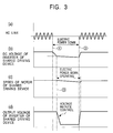
- the free run control causes a slower decrease in DC voltage based on the internal electric power source of the inverter of the shared driving device 50A as shown in Figure 3(b).
- the control of the inverter is kept effective.
- the speeds of the motors 31 to 35 of the shared driving device 50A decrease gradually a shown in Figure 3(c), this does not affect practical operations.
- the inverter of the shared driving device 50A starts a reduced load operation at the point 3 ⁇ of an instantaneous electric power failure start level to reduce the output voltage. Specifically, the voltage is reduced without varying the frequencies of the inverters 41 to 45, so that no currents are lost. Consequently, free run is carried out so as to inhibit the occurrence of torque with the rotation control of the inverters 41 to 45 remaining active. Since the shared driving device 50A has the driving shafts 141 to 145, it exerts an inertia force. Accordingly, the speed of the shared driving device 50A remains substantially unchanged during an instantaneous electric power failure lasting about 0.5 seconds.
- the drivers 30, 40, solenoid 14c, and solenoid valves 5a, 5b of the individual driving device 50B return to their steady state operations while maintaining their operational state.
- the electric power from the regenerative electric power supply circuit 54 is supplied to the control section 1A to maintain the control performed by it. If the waxing driver 48 in Figure 2 is provided in the system, the regenerative electric power supply circuit 54 supplies electric power to the driver 48.
- the electric power failure detecting section 55 Upon detecting an electric power failure, the electric power failure detecting section 55 outputs a deceleration instruction to the intra-frame member driving device 50C.
- the shared driving device 50A is supplied, via the first electric power supply bus 52a, with regenerative electric power resulting from the deceleration control performed on the intra-frame member driving device 50C.
- This regenerative electric power is also supplied to the individual driving device 50B via the regenerative electric power supply circuit 54.
- This provides an electric power source for both shared driving device 50A and individual driving device 50B during an electric power failure.
- This embodiment is applicable to the case in which the electric power failure lasts for only a short time or the intra-frame member driving device 50C exerts a strong inertia force.
- the individual driving device for each spinning unit is supplied with regenerative electric power obtained by controllably decelerating the intra-frame member driving device, which does not relate directly to the spinning carried out by the spinning unit, that is, to the bundle of fibers or the yarn. Consequently, the individual driving control device can be continuously driven without controllably decelerating the shared driving device. Therefore, the spinning can be continuously carried out without significantly varying the speed of each spinning unit. It is thus possible to prevent yarn breakage that may occur upon an electric power failure and to maintain the quality of the spun yarn during an electric power failure.
Landscapes
- Engineering & Computer Science (AREA)
- Mechanical Engineering (AREA)
- Textile Engineering (AREA)
- Spinning Or Twisting Of Yarns (AREA)
Abstract
Description
Claims (5)
- A driving control system for a spinning machine having a plurality of spinning units, individual driving devices, which are provided for the respective spinning units, for driving members acting directly on a bundle of fibers or a yarn, a shared driving device, which is provided to drive all of said plurality of spinning units, for driving members acting directly on a bundle of fibers or a yarn, and a intra-frame member driving device that drives members not acting directly on said bundle of fibers or yarn, the driving control system being characterized by comprising electric power failure detecting means for detecting an electric power failure in a system electric power source for said driving devices, deceleration control means for controllably decelerating said intra-frame member driving device, and supply means for supplying said individual driving devices for the respective spinning units with regenerative electric power resulting from said deceleration control.
- A driving control system for a spinning machine according to Claim 1, characterized by further comprising free run control means for operating said shared driving device with a light load when an electric power failure is detected.
- A driving control system for a spinning machine according to Claim 1 or Claim 2, characterized in that said intra-frame member driving device is a motor for a suction blower that sucks dust or yarn waste generated from each spinning unit as well as an inverter device for the motor.
- A driving control system for a spinning machine according to any one of Claims 1 to 3, characterized in that a work carriage that executes yarn splicing on each spinning unit is provided so as to be movable along said plurality of spinning units.
- A driving control system for a spinning machine according to any one of Claims 1 to 4, characterized in that said individual driving device is one or more combinations of a solenoid valve, solenoid, a motor, and a motor driver all of which are provided in each spinning unit.
Applications Claiming Priority (2)
| Application Number | Priority Date | Filing Date | Title |
|---|---|---|---|
| JP2003142939A JP3791511B2 (en) | 2003-05-21 | 2003-05-21 | Drive control system for spinning machine |
| JP2003142939 | 2003-05-21 |
Publications (3)
| Publication Number | Publication Date |
|---|---|
| EP1479800A2 true EP1479800A2 (en) | 2004-11-24 |
| EP1479800A3 EP1479800A3 (en) | 2005-11-16 |
| EP1479800B1 EP1479800B1 (en) | 2018-05-30 |
Family
ID=33095425
Family Applications (1)
| Application Number | Title | Priority Date | Filing Date |
|---|---|---|---|
| EP04010092.7A Expired - Lifetime EP1479800B1 (en) | 2003-05-21 | 2004-04-28 | Driving control system for spinning machine |
Country Status (3)
| Country | Link |
|---|---|
| EP (1) | EP1479800B1 (en) |
| JP (1) | JP3791511B2 (en) |
| CN (1) | CN100352159C (en) |
Cited By (5)
| Publication number | Priority date | Publication date | Assignee | Title |
|---|---|---|---|---|
| CN103806143A (en) * | 2014-02-14 | 2014-05-21 | 青岛环球集团股份有限公司 | Bidirectional transmission roving frame |
| US10008854B2 (en) | 2015-02-19 | 2018-06-26 | Enphase Energy, Inc. | Method and apparatus for time-domain droop control with integrated phasor current control |
| IT201700010272A1 (en) * | 2017-01-31 | 2018-07-31 | Savio Macch Tessili Spa | TEXTILE SPINNING MACHINE WITH ELECTRONIC APPARATUS TO PROVIDE THE TEXTILE MACHINE WITH AN ELECTRIC BACKUP POWER SUPPLY IN CASE OF INTERRUPTION OF THE AC POWER SUPPLY |
| US11296621B2 (en) | 2016-04-26 | 2022-04-05 | Dyson Technology Limited | Method for controlling an electric motor |
| CN116356462A (en) * | 2023-04-07 | 2023-06-30 | 杭州思博瑞驱动设备有限公司 | A two-for-one twister control structure and its control system |
Families Citing this family (3)
| Publication number | Priority date | Publication date | Assignee | Title |
|---|---|---|---|---|
| CN102185557A (en) * | 2011-03-26 | 2011-09-14 | 温州职业技术学院 | Speed regulation control system of single-phase induction motor |
| CZ2013275A3 (en) * | 2013-04-09 | 2014-10-22 | Rieter Cz S.R.O. | Spinning staring method on spinning machine, particularly on air jet spinning machine or rotor spinning machine |
| DE102020117904A1 (en) * | 2019-07-16 | 2021-01-21 | Oerlikon Textile Gmbh & Co. Kg | Conveyor system for recovering part of the drive energy |
Family Cites Families (6)
| Publication number | Priority date | Publication date | Assignee | Title |
|---|---|---|---|---|
| JPH02221424A (en) * | 1989-02-23 | 1990-09-04 | Hitachi Ltd | Motor-controlling apparatus for spinning frame |
| DE3910183A1 (en) * | 1989-03-29 | 1990-10-04 | Rieter Ag Maschf | Textile machine, especially ring-spinning machine |
| DE4011598A1 (en) * | 1990-04-10 | 1991-10-17 | Rieter Ag Maschf | TEXTILE MACHINE, PARTICULAR RING SPINNING MACHINE |
| DE19821251A1 (en) * | 1998-05-12 | 1999-11-18 | Csm Gmbh | Drive system for a spinning machine with a number of spindle drive motors |
| DE10000146B4 (en) * | 2000-01-04 | 2006-09-07 | Rieter Ingolstadt Spinnereimaschinenbau Ag | Method and device for controlling a component of a multitude of similar working parts juxtaposed textile machine |
| JP4566139B2 (en) * | 2006-02-10 | 2010-10-20 | コニカミノルタビジネステクノロジーズ株式会社 | Image forming system, information processing apparatus, and control program for information processing apparatus |
-
2003
- 2003-05-21 JP JP2003142939A patent/JP3791511B2/en not_active Expired - Fee Related
-
2004
- 2004-04-28 EP EP04010092.7A patent/EP1479800B1/en not_active Expired - Lifetime
- 2004-05-19 CN CNB2004100446235A patent/CN100352159C/en not_active Expired - Fee Related
Cited By (10)
| Publication number | Priority date | Publication date | Assignee | Title |
|---|---|---|---|---|
| CN103806143A (en) * | 2014-02-14 | 2014-05-21 | 青岛环球集团股份有限公司 | Bidirectional transmission roving frame |
| CN103806143B (en) * | 2014-02-14 | 2016-02-03 | 青岛环球集团股份有限公司 | Bidirectional driving Speed frames |
| US10008854B2 (en) | 2015-02-19 | 2018-06-26 | Enphase Energy, Inc. | Method and apparatus for time-domain droop control with integrated phasor current control |
| US10951037B2 (en) | 2015-02-19 | 2021-03-16 | Enphase Energy, Inc. | Method and apparatus for time-domain droop control with integrated phasor current control |
| US11355936B2 (en) | 2015-02-19 | 2022-06-07 | Enphase Energy, Inc. | Method and apparatus for time-domain droop control with integrated phasor current control |
| US11296621B2 (en) | 2016-04-26 | 2022-04-05 | Dyson Technology Limited | Method for controlling an electric motor |
| US11682988B2 (en) | 2016-04-26 | 2023-06-20 | Dyson Technology Limited | Method for controlling an electric motor |
| IT201700010272A1 (en) * | 2017-01-31 | 2018-07-31 | Savio Macch Tessili Spa | TEXTILE SPINNING MACHINE WITH ELECTRONIC APPARATUS TO PROVIDE THE TEXTILE MACHINE WITH AN ELECTRIC BACKUP POWER SUPPLY IN CASE OF INTERRUPTION OF THE AC POWER SUPPLY |
| EP3354775A1 (en) * | 2017-01-31 | 2018-08-01 | Savio Macchine Tessili S.p.A. | Spinning machine with electronic apparatus for providing the spinning machine with ac backup power supply in the case of an outage of ac power supply |
| CN116356462A (en) * | 2023-04-07 | 2023-06-30 | 杭州思博瑞驱动设备有限公司 | A two-for-one twister control structure and its control system |
Also Published As
| Publication number | Publication date |
|---|---|
| JP2004346440A (en) | 2004-12-09 |
| CN100352159C (en) | 2007-11-28 |
| EP1479800A3 (en) | 2005-11-16 |
| EP1479800B1 (en) | 2018-05-30 |
| JP3791511B2 (en) | 2006-06-28 |
| CN1574606A (en) | 2005-02-02 |
Similar Documents
| Publication | Publication Date | Title |
|---|---|---|
| CN110158207B (en) | Air spinning machine and air spinning method | |
| EP2727870A2 (en) | Yarn winding machine and yarn winding method | |
| EP2573217B1 (en) | Spinning unit, spinning machine and yarn processing method | |
| EP1479800B1 (en) | Driving control system for spinning machine | |
| EP2298971A1 (en) | Spinning machine with yarn accumulating roller | |
| JP2012218922A (en) | Yarn winding apparatus and yarn withdrawal method | |
| CN108286093B (en) | Spinning machine | |
| CN101407951A (en) | Method and device for operating open-end spinning machine | |
| JP2014108846A (en) | Yarn winding machine and textile machine including the same | |
| EP1889956A1 (en) | Wadding detecting method and device in core yarn spinning | |
| EP2862826B1 (en) | Yarn winding machine | |
| JP2014108844A (en) | Yarn winder and yarn drawing-out method | |
| CN105905680B (en) | Yarn reeling device and fiber are mechanical | |
| JP2017001836A (en) | Yarn winder and spinning machine | |
| JP2009243006A (en) | Drafter | |
| JP2014218315A (en) | Yarn winding machine | |
| JP2014108845A (en) | Yarn winding machine | |
| CN101346297B (en) | Method for spooling a thread on a textile machine which produces crosswound bobbins, and textile machine which produces crosswound bobbins | |
| CN115961390A (en) | Spinning mechanism | |
| KR100737866B1 (en) | Control device of motor in textile machinery | |
| EP1369371B1 (en) | Power failure handling system for automatic winder | |
| EP2853510B1 (en) | Service vehicle of textile machine | |
| CN110699796B (en) | Spinning mechanism of yarn | |
| JP2018127741A (en) | Yarn winder | |
| EP4112521B1 (en) | Yarn winding machine |
Legal Events
| Date | Code | Title | Description |
|---|---|---|---|
| PUAI | Public reference made under article 153(3) epc to a published international application that has entered the european phase |
Free format text: ORIGINAL CODE: 0009012 |
|
| AK | Designated contracting states |
Kind code of ref document: A2 Designated state(s): AT BE BG CH CY CZ DE DK EE ES FI FR GB GR HU IE IT LI LU MC NL PL PT RO SE SI SK TR |
|
| AX | Request for extension of the european patent |
Extension state: AL HR LT LV MK |
|
| PUAL | Search report despatched |
Free format text: ORIGINAL CODE: 0009013 |
|
| AK | Designated contracting states |
Kind code of ref document: A3 Designated state(s): AT BE BG CH CY CZ DE DK EE ES FI FR GB GR HU IE IT LI LU MC NL PL PT RO SE SI SK TR |
|
| AX | Request for extension of the european patent |
Extension state: AL HR LT LV MK |
|
| 17P | Request for examination filed |
Effective date: 20060309 |
|
| AKX | Designation fees paid |
Designated state(s): CH DE LI |
|
| 17Q | First examination report despatched |
Effective date: 20090921 |
|
| GRAP | Despatch of communication of intention to grant a patent |
Free format text: ORIGINAL CODE: EPIDOSNIGR1 |
|
| RIC1 | Information provided on ipc code assigned before grant |
Ipc: D01H 13/14 20060101AFI20180215BHEP Ipc: D01H 4/42 20060101ALI20180215BHEP |
|
| INTG | Intention to grant announced |
Effective date: 20180308 |
|
| RIN1 | Information on inventor provided before grant (corrected) |
Inventor name: NAKADE, KAZUHIKO Inventor name: NISHIKAWA, KAZUO |
|
| GRAS | Grant fee paid |
Free format text: ORIGINAL CODE: EPIDOSNIGR3 |
|
| GRAA | (expected) grant |
Free format text: ORIGINAL CODE: 0009210 |
|
| AK | Designated contracting states |
Kind code of ref document: B1 Designated state(s): CH DE LI |
|
| REG | Reference to a national code |
Ref country code: CH Ref legal event code: EP |
|
| REG | Reference to a national code |
Ref country code: CH Ref legal event code: NV Representative=s name: ING. ALESSANDRO GALASSI C/O PGA S.P.A., MILANO, CH |
|
| REG | Reference to a national code |
Ref country code: DE Ref legal event code: R096 Ref document number: 602004052755 Country of ref document: DE |
|
| REG | Reference to a national code |
Ref country code: CH Ref legal event code: PK Free format text: BERICHTIGUNGEN |
|
| RIC2 | Information provided on ipc code assigned after grant |
Ipc: D01H 4/42 20060101ALI20180215BHEP Ipc: D01H 13/14 20060101AFI20180215BHEP |
|
| REG | Reference to a national code |
Ref country code: DE Ref legal event code: R097 Ref document number: 602004052755 Country of ref document: DE |
|
| PLBE | No opposition filed within time limit |
Free format text: ORIGINAL CODE: 0009261 |
|
| STAA | Information on the status of an ep patent application or granted ep patent |
Free format text: STATUS: NO OPPOSITION FILED WITHIN TIME LIMIT |
|
| 26N | No opposition filed |
Effective date: 20190301 |
|
| PGFP | Annual fee paid to national office [announced via postgrant information from national office to epo] |
Ref country code: DE Payment date: 20190418 Year of fee payment: 16 |
|
| PGFP | Annual fee paid to national office [announced via postgrant information from national office to epo] |
Ref country code: CH Payment date: 20190418 Year of fee payment: 16 |
|
| REG | Reference to a national code |
Ref country code: DE Ref legal event code: R119 Ref document number: 602004052755 Country of ref document: DE |
|
| REG | Reference to a national code |
Ref country code: CH Ref legal event code: PL |
|
| PG25 | Lapsed in a contracting state [announced via postgrant information from national office to epo] |
Ref country code: CH Free format text: LAPSE BECAUSE OF NON-PAYMENT OF DUE FEES Effective date: 20200430 Ref country code: DE Free format text: LAPSE BECAUSE OF NON-PAYMENT OF DUE FEES Effective date: 20201103 Ref country code: LI Free format text: LAPSE BECAUSE OF NON-PAYMENT OF DUE FEES Effective date: 20200430 |