EP1479656A2 - Bond coat for silicon based substrates - Google Patents
Bond coat for silicon based substrates Download PDFInfo
- Publication number
- EP1479656A2 EP1479656A2 EP04253014A EP04253014A EP1479656A2 EP 1479656 A2 EP1479656 A2 EP 1479656A2 EP 04253014 A EP04253014 A EP 04253014A EP 04253014 A EP04253014 A EP 04253014A EP 1479656 A2 EP1479656 A2 EP 1479656A2
- Authority
- EP
- European Patent Office
- Prior art keywords
- silicon
- refractory metal
- bond layer
- metal disilicide
- article according
- Prior art date
- Legal status (The legal status is an assumption and is not a legal conclusion. Google has not performed a legal analysis and makes no representation as to the accuracy of the status listed.)
- Granted
Links
Images
Classifications
-
- C—CHEMISTRY; METALLURGY
- C04—CEMENTS; CONCRETE; ARTIFICIAL STONE; CERAMICS; REFRACTORIES
- C04B—LIME, MAGNESIA; SLAG; CEMENTS; COMPOSITIONS THEREOF, e.g. MORTARS, CONCRETE OR LIKE BUILDING MATERIALS; ARTIFICIAL STONE; CERAMICS; REFRACTORIES; TREATMENT OF NATURAL STONE
- C04B41/00—After-treatment of mortars, concrete, artificial stone or ceramics; Treatment of natural stone
- C04B41/009—After-treatment of mortars, concrete, artificial stone or ceramics; Treatment of natural stone characterised by the material treated
-
- C—CHEMISTRY; METALLURGY
- C04—CEMENTS; CONCRETE; ARTIFICIAL STONE; CERAMICS; REFRACTORIES
- C04B—LIME, MAGNESIA; SLAG; CEMENTS; COMPOSITIONS THEREOF, e.g. MORTARS, CONCRETE OR LIKE BUILDING MATERIALS; ARTIFICIAL STONE; CERAMICS; REFRACTORIES; TREATMENT OF NATURAL STONE
- C04B41/00—After-treatment of mortars, concrete, artificial stone or ceramics; Treatment of natural stone
- C04B41/45—Coating or impregnating, e.g. injection in masonry, partial coating of green or fired ceramics, organic coating compositions for adhering together two concrete elements
- C04B41/50—Coating or impregnating, e.g. injection in masonry, partial coating of green or fired ceramics, organic coating compositions for adhering together two concrete elements with inorganic materials
- C04B41/5053—Coating or impregnating, e.g. injection in masonry, partial coating of green or fired ceramics, organic coating compositions for adhering together two concrete elements with inorganic materials non-oxide ceramics
- C04B41/5062—Borides, Nitrides or Silicides
- C04B41/5071—Silicides
-
- C—CHEMISTRY; METALLURGY
- C04—CEMENTS; CONCRETE; ARTIFICIAL STONE; CERAMICS; REFRACTORIES
- C04B—LIME, MAGNESIA; SLAG; CEMENTS; COMPOSITIONS THEREOF, e.g. MORTARS, CONCRETE OR LIKE BUILDING MATERIALS; ARTIFICIAL STONE; CERAMICS; REFRACTORIES; TREATMENT OF NATURAL STONE
- C04B41/00—After-treatment of mortars, concrete, artificial stone or ceramics; Treatment of natural stone
- C04B41/80—After-treatment of mortars, concrete, artificial stone or ceramics; Treatment of natural stone of only ceramics
- C04B41/81—Coating or impregnation
- C04B41/85—Coating or impregnation with inorganic materials
- C04B41/87—Ceramics
-
- C—CHEMISTRY; METALLURGY
- C23—COATING METALLIC MATERIAL; COATING MATERIAL WITH METALLIC MATERIAL; CHEMICAL SURFACE TREATMENT; DIFFUSION TREATMENT OF METALLIC MATERIAL; COATING BY VACUUM EVAPORATION, BY SPUTTERING, BY ION IMPLANTATION OR BY CHEMICAL VAPOUR DEPOSITION, IN GENERAL; INHIBITING CORROSION OF METALLIC MATERIAL OR INCRUSTATION IN GENERAL
- C23C—COATING METALLIC MATERIAL; COATING MATERIAL WITH METALLIC MATERIAL; SURFACE TREATMENT OF METALLIC MATERIAL BY DIFFUSION INTO THE SURFACE, BY CHEMICAL CONVERSION OR SUBSTITUTION; COATING BY VACUUM EVAPORATION, BY SPUTTERING, BY ION IMPLANTATION OR BY CHEMICAL VAPOUR DEPOSITION, IN GENERAL
- C23C30/00—Coating with metallic material characterised only by the composition of the metallic material, i.e. not characterised by the coating process
-
- F—MECHANICAL ENGINEERING; LIGHTING; HEATING; WEAPONS; BLASTING
- F01—MACHINES OR ENGINES IN GENERAL; ENGINE PLANTS IN GENERAL; STEAM ENGINES
- F01D—NON-POSITIVE DISPLACEMENT MACHINES OR ENGINES, e.g. STEAM TURBINES
- F01D5/00—Blades; Blade-carrying members; Heating, heat-insulating, cooling or antivibration means on the blades or the members
- F01D5/12—Blades
- F01D5/28—Selecting particular materials; Particular measures relating thereto; Measures against erosion or corrosion
- F01D5/288—Protective coatings for blades
Definitions
- the present invention is drawn to an environmental barrier coating and, more particularly, an environmental barrier coating applied to a silicon containing substrate.
- Silicon based ceramics exhibit accelerated oxidation rates in high temperature, aqueous environments such as for example, the combustor and turbine sections of gas turbine engines.
- environment barrier coating i.e., barrier layer(s)
- barrier layer(s) for the silicon based substrates so as to increase the service life of such component parts.
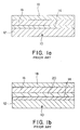
- prior art environmental barrier coatings form a composite 10 comprising a silicon based substrate 12, a bond coat or layer 14 such as a dense continuous layer of silicon metal, a barrier layer 16 such as either an alkaline earth aluminosilicate based on barium and strontium, or yttrium silicate, and an optional top layer such as a refractory oxide and/or silicate layer 18 or other metal oxide such as for example zirconium oxide.
- an intermediate layer 20 may be provided between the 14 bond coat and the barrier 16 and/or between the barrier layer 16 and the top layer 18.
- the intermediate layer comprises, for example, a mixture of the barrier layer material with an additional oxide such as mullite.
- the foregoing object is achieved by the present invention by providing an improved bond layer for use on a silicon based substrate.
- the bond layer comprises an alloy comprising a refractory metal disilicide/silicon eutectic.
- the refractory metal disilicide is selected from the group consisting of disilicides of molybdenum, chromium, hafnium, niobium, tantalum, rhenium, titanium, tungsten, uranium, vanadium, yttrium and mixtures thereof.
- the refractory metal disilicide/silicon eutectic has a melting point of greater than 1300°C.
- the particular advantage achieved by the present invention is an increase in room temperature fracture toughness when compared to silicon metal bond layers as discussed above. It has been found that the fracture toughness of the bond coat is increased by more than 50% over that achievable with a simple phase silicon metal bond coat. This increase in fracture toughness is attributable to the mechanism of the two phase microstructure of the present invention which provides more resistance to crack propagation than that observed in a single phase, silicon layer.
- the present invention relates to an article comprising a silicon base substrate and a bond layer.
- the bond layer may be applied directly on the silicon base substrate or, alternatively, a silicon oxide intermediate layer or other intermediate layer may be provided between the bond layer and the silicon base substrate.
- the silicon containing substrate may be a silicon ceramic substrate or a silicon containing metal alloy.
- the silicon containing substrate is a silicon containing ceramic material as, for example, silicon carbide, silicon carbide composite, silicon nitride, silicon nitride composite, silicon oxynitride and silicon aluminum oxynitride.
- the bond layer comprises an alloy comprising a refractory metal disilicide/silicon eutectic.
- the bond layer may comprise 100% of the refractory metal disilicide/silicon eutectic or the bond layer may comprise a multiphase microstructure of the refractory metal disilicide/silicon eutectic alone or with either silicon or the refractory metal disilicide.
- the refractory metal disilicide/silicon eutectic has a melting point of greater than 1300°C.
- the silicon content of the bond layer is greater than or equal to 66.7 atomic percent silicon, preferably 80 atomic percent silicon, with the balance being the refractory metal.
- Preferred refractory metals used in the bond layer of the present invention are selected from the group consisting of molybdenum, chromium, hafnium, niobium, tantalum, rhenium, titanium, tungsten, uranium, vanadium, yttrium and mixtures thereof.
- Preferred refractory metals are molybdenum and chromium and the most preferred refractory metal is molybdenum.
- the article of the present invention exhibits significant improvement in fracture toughness over silicon metal bond layers known in the prior art, that is, a fracture toughness of greater than 1 MPa-m 1 ⁇ 2 .
Landscapes
- Chemical & Material Sciences (AREA)
- Engineering & Computer Science (AREA)
- Ceramic Engineering (AREA)
- Materials Engineering (AREA)
- Organic Chemistry (AREA)
- Structural Engineering (AREA)
- Inorganic Chemistry (AREA)
- Mechanical Engineering (AREA)
- Chemical Kinetics & Catalysis (AREA)
- Metallurgy (AREA)
- General Engineering & Computer Science (AREA)
- Laminated Bodies (AREA)
- Other Surface Treatments For Metallic Materials (AREA)
- Turbine Rotor Nozzle Sealing (AREA)
- Ceramic Products (AREA)
Abstract
Description
Claims (10)
- An article (10) comprising a silicon based substrate (12) and a bond layer (14), the bond layer (14) comprising an alloy comprising a refractory metal disilicide/silicon eutectic.
- An article according to claim 1, wherein the refractory metal disilicide is selected from the group consisting of disilicides of molybdenum, chromium, hafnium, niobium, rhenium, tantalum, titanium, tungsten, uranium, vanadium, yttrium and mixtures thereof.
- An article according to claim 1 or 2, wherein the refractory metal disilicide/silicon eutectic has a melting point of greater than 1300°C.
- An article according to claim 1, 2 or 3, wherein the bond layer (14) comprises a multiphase microstructure of the refractory metal disilicide/silicon eutectic and silicon.
- An article according to claim 1, 2 or 3, wherein the bond layer (14) comprises a multiphase microstructure of the refractory metal disilicide/silicon eutectic and refractory metal disilicide.
- An article according to claim 1, 2 or 3, wherein the bond layer (14) comprises a multiphase microstructure of the refractory metal disilicide/silicon eutectic and one of silicon and refractory metal disilicide.
- An article according to claim 4, 5 or 6 wherein the fracture toughness is greater than 1 MPa·m½.
- An article according to any preceding claim, wherein silicon is present in an amount greater than or equal to 66.7 atomic percent.
- An article according to any preceding claim, wherein silicon is present in an amount greater than or equal to 80 atomic percent.
- An article (10) comprising a silicon substrate (12) and a bond layer (14), the bond layer (14) comprising a multi-phase alloy having a fracture toughness greater than 1MPa.m½.
Applications Claiming Priority (2)
| Application Number | Priority Date | Filing Date | Title |
|---|---|---|---|
| US10/443,342 US7060360B2 (en) | 2003-05-22 | 2003-05-22 | Bond coat for silicon based substrates |
| US443342 | 2003-05-22 |
Publications (3)
| Publication Number | Publication Date |
|---|---|
| EP1479656A2 true EP1479656A2 (en) | 2004-11-24 |
| EP1479656A3 EP1479656A3 (en) | 2005-08-17 |
| EP1479656B1 EP1479656B1 (en) | 2007-08-15 |
Family
ID=33098003
Family Applications (1)
| Application Number | Title | Priority Date | Filing Date |
|---|---|---|---|
| EP04253014A Expired - Lifetime EP1479656B1 (en) | 2003-05-22 | 2004-05-21 | Bond coat for silicon based substrates |
Country Status (5)
| Country | Link |
|---|---|
| US (1) | US7060360B2 (en) |
| EP (1) | EP1479656B1 (en) |
| JP (1) | JP2004345948A (en) |
| CN (1) | CN1609060A (en) |
| DE (1) | DE602004008145T2 (en) |
Cited By (7)
| Publication number | Priority date | Publication date | Assignee | Title |
|---|---|---|---|---|
| EP1726681A1 (en) * | 2005-05-23 | 2006-11-29 | United Technologies Corporation | Coating system for silicon based substrates |
| GB2427204A (en) * | 2005-06-13 | 2006-12-20 | Gen Electric | Intermediate bond coat for silicon containing substrate |
| GB2427205A (en) * | 2005-06-13 | 2006-12-20 | Gen Electric | Intermediate bond coat for silicon containing substrate |
| WO2007066052A3 (en) * | 2005-12-08 | 2008-04-24 | Snecma | Joint between a metal part and a ceramic part based sic and/or c |
| FR2907448A1 (en) * | 2007-09-25 | 2008-04-25 | Snecma Sa | BRAZING COMPOSITION AND BRAZING ASSEMBLY PROCESS USING THE SAME |
| EP1842937A3 (en) * | 2006-03-13 | 2008-08-27 | United Technologies Corporation | Bond coating and thermal barrier compositions, processes for applying both, and their coated articles |
| WO2011022058A1 (en) * | 2009-08-21 | 2011-02-24 | Massachusetts Institute Of Technology | Silicon-rich alloys |
Families Citing this family (31)
| Publication number | Priority date | Publication date | Assignee | Title |
|---|---|---|---|---|
| US20090297866A1 (en) * | 2006-07-31 | 2009-12-03 | Honeywell International, Inc. | Components and methods of forming protective coating systems on components |
| US7951459B2 (en) | 2006-11-21 | 2011-05-31 | United Technologies Corporation | Oxidation resistant coatings, processes for coating articles, and their coated articles |
| US8323796B2 (en) | 2007-07-17 | 2012-12-04 | United Technologies Corporation | High temperature refractory coatings for ceramic substrates |
| CN101407124B (en) * | 2008-12-01 | 2013-04-24 | 贵研铂业股份有限公司 | Nb/Re composite multilayer material and preparation thereof |
| US20110097589A1 (en) * | 2009-10-28 | 2011-04-28 | General Electric Company | Article for high temperature service |
| US20110206937A1 (en) * | 2010-02-25 | 2011-08-25 | Schmidt Wayde R | Composite article having a ceramic nanocomposite layer |
| US8470457B2 (en) * | 2010-03-29 | 2013-06-25 | United Technologies Corporation | Composite article having a solid solution protective layer |
| JP5766445B2 (en) * | 2011-01-17 | 2015-08-19 | 山陽特殊製鋼株式会社 | Si alloy powder for negative electrode of lithium ion secondary battery and manufacturing method thereof |
| JP2015517057A (en) * | 2011-12-23 | 2015-06-18 | ダウ コーニング コーポレーションDow Corning Corporation | Industrial component comprising a silicon eutectic alloy and method of making the component |
| US10774682B2 (en) | 2012-06-22 | 2020-09-15 | The United States of America as Represented by the Administrator of National Aeromautics and Space Administration | Advanced high temperature and fatigue resistant environmental barrier coating bond coat systems for SiC/SiC ceramic matrix composites |
| US20140050929A1 (en) * | 2012-08-15 | 2014-02-20 | General Electric Company | Cavitation-resistant environmental barrier coatings |
| US20140050930A1 (en) * | 2012-08-16 | 2014-02-20 | General Electric Company | Creep-resistant environmental barrier coatings |
| WO2014204480A1 (en) * | 2013-06-21 | 2014-12-24 | United States Of America, As Represented By The Administrator Of The National Aeronautics And Space Administration | Environmental barrier coating bond coat systems |
| EP3141631B1 (en) | 2015-09-10 | 2018-03-14 | Rolls-Royce High Temperature Composites Inc | Applying silicon metal-containing bond layer to ceramic or ceramic matrix composite substrates |
| US20170327937A1 (en) | 2016-05-11 | 2017-11-16 | United Technologies Corporation | High temperature coating for silicon nitride articles |
| US10604454B1 (en) | 2016-06-16 | 2020-03-31 | United States Of America As Represented By The Administrator Of National Aeronautics And Space Administration | Advanced high temperature environmental barrier coating for SiC/SiC ceramic matrix composites |
| US10384978B2 (en) * | 2016-08-22 | 2019-08-20 | General Electric Company | Thermal barrier coating repair compositions and methods of use thereof |
| US11958786B1 (en) | 2016-12-05 | 2024-04-16 | United States Government Administrator Of Nasa | Calcium-magnesium aluminosilicate (CMAS) resistant thermal and environmental barrier coatings |
| US11066339B2 (en) * | 2017-06-08 | 2021-07-20 | General Electric Company | Article for high temperature service |
| AT16355U1 (en) * | 2017-06-30 | 2019-07-15 | Plansee Se | slinger |
| US10822285B2 (en) | 2017-08-29 | 2020-11-03 | General Electric Company | Compositions for erosion and molten dust resistant environmental barrier coatings |
| US10696601B2 (en) | 2017-08-29 | 2020-06-30 | General Electric Company | Compositions for erosion and molten dust resistant environmental barrier coatings |
| US11639315B2 (en) | 2017-09-07 | 2023-05-02 | General Electric Company | Bond coatings having a molten silicon-phase contained between refractory layers |
| US11401217B2 (en) | 2017-09-07 | 2022-08-02 | General Electric Company | Bond coatings having a silicon-phase contained within a refractory phase |
| US11773734B2 (en) | 2017-09-07 | 2023-10-03 | General Electric Company | Liquid bond coatings for barrier coatings |
| US12479766B2 (en) * | 2018-08-30 | 2025-11-25 | University Of Virginia Patent Foundation | Functional barrier coating and related methods thereof |
| CN111451501B (en) * | 2020-04-03 | 2021-12-21 | 季华实验室 | Preparation method for laser additive manufacturing of tungsten part based on eutectic reaction |
| US11845701B2 (en) | 2020-07-21 | 2023-12-19 | Rolls-Royce Corporation | EBC layer containing boron |
| US11851380B2 (en) | 2021-05-26 | 2023-12-26 | General Electric Company | Slurry processing for deposition of rare earth hafnium tantalate based barrier coatings |
| US12637393B2 (en) | 2022-09-01 | 2026-05-26 | Rolls-Royce Corporation | Advanced coating chemistries for CMCS |
| US12679782B2 (en) | 2023-03-02 | 2026-07-14 | Rolls-Royce Corporation | Coating layer with slow SIO2 crystallization rate |
Family Cites Families (7)
| Publication number | Priority date | Publication date | Assignee | Title |
|---|---|---|---|---|
| RU2082824C1 (en) * | 1994-03-10 | 1997-06-27 | Московский государственный авиационный институт (технический университет) | Method of protection of heat-resistant material from effect of high-rapid gaseous flow of corrosive media (variants) |
| US6299988B1 (en) | 1998-04-27 | 2001-10-09 | General Electric Company | Ceramic with preferential oxygen reactive layer |
| US6296942B1 (en) | 1999-04-15 | 2001-10-02 | General Electric Company | Silicon based substrate with calcium aluminosilicate environmental/thermal barrier layer |
| US6410148B1 (en) * | 1999-04-15 | 2002-06-25 | General Electric Co. | Silicon based substrate with environmental/ thermal barrier layer |
| US6296941B1 (en) | 1999-04-15 | 2001-10-02 | General Electric Company | Silicon based substrate with yttrium silicate environmental/thermal barrier layer |
| US6254935B1 (en) | 1999-04-15 | 2001-07-03 | United Technologies Corporation | Method for applying a barrier layer to a silicon based substrate |
| US6352790B1 (en) | 2000-06-29 | 2002-03-05 | United Technologies Corporation | Substrate containing silicon and a barrier layer which functions as a protective/thermal barrier coating |
-
2003
- 2003-05-22 US US10/443,342 patent/US7060360B2/en not_active Expired - Lifetime
-
2004
- 2004-05-21 DE DE602004008145T patent/DE602004008145T2/en not_active Expired - Lifetime
- 2004-05-21 EP EP04253014A patent/EP1479656B1/en not_active Expired - Lifetime
- 2004-05-21 CN CNA2004100595210A patent/CN1609060A/en active Pending
- 2004-05-24 JP JP2004152720A patent/JP2004345948A/en active Pending
Cited By (11)
| Publication number | Priority date | Publication date | Assignee | Title |
|---|---|---|---|---|
| EP1726681A1 (en) * | 2005-05-23 | 2006-11-29 | United Technologies Corporation | Coating system for silicon based substrates |
| US7374818B2 (en) | 2005-05-23 | 2008-05-20 | United Technologies Corporation | Coating system for silicon based substrates |
| GB2427204A (en) * | 2005-06-13 | 2006-12-20 | Gen Electric | Intermediate bond coat for silicon containing substrate |
| GB2427205A (en) * | 2005-06-13 | 2006-12-20 | Gen Electric | Intermediate bond coat for silicon containing substrate |
| GB2427205B (en) * | 2005-06-13 | 2011-06-15 | Gen Electric | Bond coat for corrosion resistant EBC for silicon-containing substrate and processes for preparing same |
| WO2007066052A3 (en) * | 2005-12-08 | 2008-04-24 | Snecma | Joint between a metal part and a ceramic part based sic and/or c |
| US8177497B2 (en) | 2005-12-08 | 2012-05-15 | Snecma | Joint between a metal part and a ceramic part based SiC and/or C |
| EP1842937A3 (en) * | 2006-03-13 | 2008-08-27 | United Technologies Corporation | Bond coating and thermal barrier compositions, processes for applying both, and their coated articles |
| FR2907448A1 (en) * | 2007-09-25 | 2008-04-25 | Snecma Sa | BRAZING COMPOSITION AND BRAZING ASSEMBLY PROCESS USING THE SAME |
| WO2011022058A1 (en) * | 2009-08-21 | 2011-02-24 | Massachusetts Institute Of Technology | Silicon-rich alloys |
| EP2878693A1 (en) * | 2009-08-21 | 2015-06-03 | Massachusetts Institute of Technology | Silicon-rich alloys |
Also Published As
| Publication number | Publication date |
|---|---|
| US7060360B2 (en) | 2006-06-13 |
| EP1479656B1 (en) | 2007-08-15 |
| US20040234784A1 (en) | 2004-11-25 |
| DE602004008145T2 (en) | 2008-04-30 |
| CN1609060A (en) | 2005-04-27 |
| EP1479656A3 (en) | 2005-08-17 |
| JP2004345948A (en) | 2004-12-09 |
| DE602004008145D1 (en) | 2007-09-27 |
Similar Documents
| Publication | Publication Date | Title |
|---|---|---|
| US7060360B2 (en) | Bond coat for silicon based substrates | |
| US7063894B2 (en) | Environmental barrier coating for silicon based substrates | |
| EP1479659B1 (en) | Bond coating for silicon based substrates such as silicon nitride | |
| US7763356B2 (en) | Bond coating and thermal barrier compositions, processes for applying both, and their coated articles | |
| US7357994B2 (en) | Thermal/environmental barrier coating system for silicon-containing materials | |
| Nicholas et al. | Ceramic/metal joining for structural applications | |
| EP1479661B1 (en) | Coating for silicon containing substrate | |
| US6759151B1 (en) | Multilayer article characterized by low coefficient of thermal expansion outer layer | |
| US10807912B1 (en) | Advanced high temperature environmental barrier coating systems for SiC/SiC ceramic matrix composites | |
| EP2138477A2 (en) | Protective coatings for silicon based substrates with improved adhesion | |
| US9719174B2 (en) | Article having composite coating | |
| US7407718B2 (en) | Thermal/environmental barrier coating system for silicon-containing materials | |
| WO2014204480A1 (en) | Environmental barrier coating bond coat systems | |
| EP1479660B1 (en) | Coating for silicon containing substrate | |
| US20050129973A1 (en) | Velocity barrier layer for environmental barrier coatings | |
| US20110097589A1 (en) | Article for high temperature service | |
| EP1479658B1 (en) | Gas turbine engine combustor or turbine section | |
| JP4175808B2 (en) | High strength molybdenum silicide material | |
| JP2004250788A (en) | Film formation method | |
| JPH0558743A (en) | High strength ceramic tappet shim |
Legal Events
| Date | Code | Title | Description |
|---|---|---|---|
| PUAI | Public reference made under article 153(3) epc to a published international application that has entered the european phase |
Free format text: ORIGINAL CODE: 0009012 |
|
| AK | Designated contracting states |
Kind code of ref document: A2 Designated state(s): AT BE BG CH CY CZ DE DK EE ES FI FR GB GR HU IE IT LI LU MC NL PL PT RO SE SI SK TR |
|
| AX | Request for extension of the european patent |
Extension state: AL HR LT LV MK |
|
| PUAL | Search report despatched |
Free format text: ORIGINAL CODE: 0009013 |
|
| AK | Designated contracting states |
Kind code of ref document: A3 Designated state(s): AT BE BG CH CY CZ DE DK EE ES FI FR GB GR HU IE IT LI LU MC NL PL PT RO SE SI SK TR |
|
| AX | Request for extension of the european patent |
Extension state: AL HR LT LV MK |
|
| 17P | Request for examination filed |
Effective date: 20060111 |
|
| AKX | Designation fees paid |
Designated state(s): DE FR GB IT NL |
|
| GRAP | Despatch of communication of intention to grant a patent |
Free format text: ORIGINAL CODE: EPIDOSNIGR1 |
|
| GRAS | Grant fee paid |
Free format text: ORIGINAL CODE: EPIDOSNIGR3 |
|
| GRAA | (expected) grant |
Free format text: ORIGINAL CODE: 0009210 |
|
| AK | Designated contracting states |
Kind code of ref document: B1 Designated state(s): DE FR GB IT NL |
|
| REG | Reference to a national code |
Ref country code: GB Ref legal event code: FG4D |
|
| REF | Corresponds to: |
Ref document number: 602004008145 Country of ref document: DE Date of ref document: 20070927 Kind code of ref document: P |
|
| EN | Fr: translation not filed | ||
| PLBE | No opposition filed within time limit |
Free format text: ORIGINAL CODE: 0009261 |
|
| STAA | Information on the status of an ep patent application or granted ep patent |
Free format text: STATUS: NO OPPOSITION FILED WITHIN TIME LIMIT |
|
| 26N | No opposition filed |
Effective date: 20080516 |
|
| PGFP | Annual fee paid to national office [announced via postgrant information from national office to epo] |
Ref country code: NL Payment date: 20080410 Year of fee payment: 5 |
|
| NLV4 | Nl: lapsed or anulled due to non-payment of the annual fee |
Effective date: 20091201 |
|
| PG25 | Lapsed in a contracting state [announced via postgrant information from national office to epo] |
Ref country code: NL Free format text: LAPSE BECAUSE OF NON-PAYMENT OF DUE FEES Effective date: 20091201 |
|
| PG25 | Lapsed in a contracting state [announced via postgrant information from national office to epo] |
Ref country code: IT Free format text: LAPSE BECAUSE OF NON-PAYMENT OF DUE FEES Effective date: 20080531 |
|
| PG25 | Lapsed in a contracting state [announced via postgrant information from national office to epo] |
Ref country code: FR Free format text: LAPSE BECAUSE OF FAILURE TO SUBMIT A TRANSLATION OF THE DESCRIPTION OR TO PAY THE FEE WITHIN THE PRESCRIBED TIME-LIMIT Effective date: 20080411 |
|
| REG | Reference to a national code |
Ref country code: DE Ref legal event code: R082 Ref document number: 602004008145 Country of ref document: DE Representative=s name: SCHMITT-NILSON SCHRAUD WAIBEL WOHLFROM PATENTA, DE |
|
| REG | Reference to a national code |
Ref country code: DE Ref legal event code: R082 Ref document number: 602004008145 Country of ref document: DE Representative=s name: SCHMITT-NILSON SCHRAUD WAIBEL WOHLFROM PATENTA, DE Ref country code: DE Ref legal event code: R081 Ref document number: 602004008145 Country of ref document: DE Owner name: UNITED TECHNOLOGIES CORP. (N.D.GES.D. STAATES , US Free format text: FORMER OWNER: UNITED TECHNOLOGIES CORP., HARTFORD, CONN., US |
|
| REG | Reference to a national code |
Ref country code: DE Ref legal event code: R081 Ref document number: 602004008145 Country of ref document: DE Owner name: RAYTHEON TECHNOLOGIES CORPORATION (N.D.GES.D.S, US Free format text: FORMER OWNER: UNITED TECHNOLOGIES CORP. (N.D.GES.D. STAATES DELAWARE), FARMINGTON, CONN., US |
|
| PGFP | Annual fee paid to national office [announced via postgrant information from national office to epo] |
Ref country code: DE Payment date: 20230419 Year of fee payment: 20 |
|
| PGFP | Annual fee paid to national office [announced via postgrant information from national office to epo] |
Ref country code: GB Payment date: 20230420 Year of fee payment: 20 |
|
| REG | Reference to a national code |
Ref country code: DE Ref legal event code: R071 Ref document number: 602004008145 Country of ref document: DE |
|
| REG | Reference to a national code |
Ref country code: GB Ref legal event code: PE20 Expiry date: 20240520 |
|
| PG25 | Lapsed in a contracting state [announced via postgrant information from national office to epo] |
Ref country code: GB Free format text: LAPSE BECAUSE OF EXPIRATION OF PROTECTION Effective date: 20240520 |
|
| PG25 | Lapsed in a contracting state [announced via postgrant information from national office to epo] |
Ref country code: GB Free format text: LAPSE BECAUSE OF EXPIRATION OF PROTECTION Effective date: 20240520 |