TECHNICAL FIELD
The present invention relates to a high-speed inclined
portion escalator in which a traveling speed of steps in an
intermediate inc lined portion is higher than the traveling speed
of the steps in an upper landing portion and a lower landing
portion.
BACKGROUND ART
In recent years, a large number of escalators having high
lift ranges have been installed in subway stations, etc. In
escalators of this kind, passengers must stand still on the
steps for a long time, and many passengers feel uncomfortable.
Because of this, escalators that operate at high speeds have
been developed, but there is an upper limit to the operating
speeds thereof for passengers to get on and off safely.
In answer to this, high-speed inclined portion escalators
have been proposed in which it is possible for the amount of
time spent riding the escalator to be shortened by operating
at low speed at upper and lower landing portions where the
passengers get on and off, operating to accelerate and decelerate
in an upper curved portion and a lower curved portion, and
operating at high speed in the intermediate inclined portion.
A high-speed inclined portion escalator of this kind is disclosed
in Japanese Patent Laid-Open No. SHO 51-116586 (Gazette), for
example.
However, since the conventional high-speed inclined
portion escalator merely performs acceleration and
deceleration from low-speed operation to high-speed operation,
or from high-speed operation to low-speed operation, a large
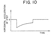
acceleration such as that shown in Figure 10 (deceleration in
the figure), for example, arises in the steps in the
speed-changing regions, and there is a risk that passengers
riding the steps will be subjected to discomfort.
DISCLOSURE OF THE INVENTION
The present invention aims to solve the above problems
and an object of the present invention is to provide a high-speed
inclined portion escalator enabling smooth speed changing to
be performed without imparting a large acceleration.
In order to achieve the above object, according to one
aspect of the present invention, there is provided a high-speed
inclined portion escalator including: a main frame; a drive
rail disposed on the main frame, the main track forming a cyclic
path; a plurality of steps having a tread, a riser disposed
on an edge portion of the tread, a step link roller shaft, and
a step link roller rolling around the step link roller shaft,
the step link roller being guided by the main track, the plurality
of steps being linked endlessly and being moved cyclically along
the cyclic path, a plurality of linking mechanisms for linking
the step link roller shafts of mutually-adjacent pairs of the
steps and changing a pitch between the step link roller shafts
by changing shape, a rotatable auxiliary roller disposed on
each of the linking mechanisms; and an auxiliary track disposed
on the main frame, the auxiliary track changing a traveling
speed of the steps depending on position by guiding movement
of the auxiliary rollers to change the shape of the linking
mechanisms, wherein: a shape for the auxiliary track in a
speed-changing region for the steps is determined by finding
a positional relationship between the step link roller shafts
of at least one of the steps and an adjacent step from a step
speed profile representing a speed of the step link roller shafts
relative to time, and a shape for the riser is determined such
that the riser aligns with a relative movement locus of the
adjacent step by finding a relative positional relationship
between the step and the adjacent step from the step speed
profile.
BRIEF DESCRIPTION OF THE DRAWINGS
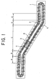
Figure 1 is a schematic side elevation showing a high-speed
inclined portion escalator according to an example of a preferred
embodiment of the present invention;
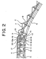
Figure 2 is a side elevation showing a vicinity of an
upper curved portion in Figure 1 enlarged;
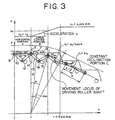
Figure 3 is an explanatory diagram explaining a method
for determining a shape for risers and shapes for auxiliary
tracks according to Embodiment 1;
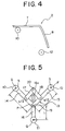
Figure 4 is a side elevation showing an example of a riser
shape according to Embodiment 1;
Figure 5 is a front elevation showing a linking mechanism
from Figure 2 enlarged;
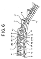
Figure 6 is a side elevation showing an example of shapes
for the auxiliary tracks according to Embodiment 1;
Figure 7 is an explanatory diagram explaining a method
for determining a shape for risers and shapes for auxiliary
tracks according to Embodiment 2 of the present invention;
Figure 8 is a side elevation showing an example of a riser
shape according to Embodiment 2;
Figure 9 is a side elevation showing an example of shapes
for the auxiliary tracks according to Embodiment 2; and
Figure 10 is a graph of a relationship between time and
acceleration showing an example of acceleration occurring in
steps in a speed-changing region of a conventional high-speed
inclined portion escalator.
BEST MODE FOR CARRYING OUT THE INVENTION
Preferred embodiments of the present invention will now
be explained with reference to the drawings.
Embodiment 1
Figure 1 is a schematic side elevation showing a high-speed
inclined portion escalator according to an example of a preferred
embodiment of the present invention. In the figure, a plurality
of steps 2 linked endlessly are disposed in a main frame 1.
The steps 2 are driven by a drive unit (a step driving means)
3, and are moved cyclically.
A pair of main tracks 4 forming a cyclic path for the
steps 2, a pair of trailing tracks 5 for controlling the attitude
of the steps 2, and a pair of auxiliary tracks 6 for changing
a pitch between adjacent steps 2 are disposed on the main frame
1.
The cyclic path for the steps 2 has: a forward section,
a return section, an upper inversion portion, and a lower
inversion portion. The forward section of the cyclic path has:
an upper landing portion (an upper horizontal portion) A, an
upper curved portion B, an intermediate inclined portion (a
constant inclination portion) C, a lower curved portion D, and
a lower landing portion (a lower horizontal portion) E.
Next, Figure 2 is a side elevation showing a vicinity
of the upper curved portion B in Figure 1 enlarged. The steps
2 have: treads 7 for carrying passengers; curved risers 8 formed
on one edge in a depth direction of the treads 7; step link
roller shafts 9; pairs of step link rollers 10 that are rotatable
around the step link roller shafts 9; trailing roller shafts
11; and pairs of trailing rollers 12 that are rotatable around
the trailing roller shafts 11. The step link rollers 10 roll
along the main tracks 4. The trailing rollers 12 roll along
the trailing tracks 5.
The step link roller shafts 9 of adjacent steps 2 are
linked to each other by linking mechanisms (folding links) 13.
Each of the linking mechanisms 13 has first to fifth links 14
to 18.
First end portions of the first links 14 are linked
pivotably to the step link roller shafts 9. Second end portions
of the first links 14 are linked pivotably to intermediate
portions of the third links 16 by means of shafts 19. First
end portions of the second links 15 are linked pivotably to
the step link roller shafts 9 of the adjacent steps 2. Second
end portions of the second links 15 are linked pivotably by
means of the shafts 19 to the intermediate portions of the third
links 16.
First end portions of the fourth links 17 are connected
pivotably to intermediate portions of the first links 14. First
end portions of the fifth links 18 are connected pivotably to
intermediate portions of the second links 15. Second end
portions of the fourth and fifth links 17 and 18 are linked
to first end portions of the third links 16 by means of sliding
shafts 20.
Guiding grooves 16a for guiding sliding of the sliding
shafts 20 in the longitudinal direction of the third links 16
are disposed on the first end portions of the third links 16.
Rotatable auxiliary rollers 21 are disposed on second end
portions of the third links 16. The auxiliary rollers 21 are
guided by the auxiliary tracks 6.
A pitch between the step link roller shafts 9, and thus
a relative pitch between adjacent steps 2, is changed by the
auxiliary rollers 21 being guided by the auxiliary tracks 6
to change the shape of the linking mechanisms 13 so as to fold
and unfold. Conversely, tracks of the auxiliary tracks 6 are
designed such that the relative pitch between adjacent steps
2 changes.
Next, operation will be explained. The speed of the steps
2 is changed by changing the pitch between the step link roller
shafts 9 of adjacent steps 2. In other words, the pitch between
the step link roller shafts 9 is minimized in the upper landing
portion A and the lower landing portion E where the passengers
get on and off, and the steps 2 move at low speed. The pitch
between the step link roller shafts 9 is maximized in the
intermediate inclined portion C, and the steps 2 move at high
speed. In addition, the pitch between the step link roller
shafts 9 changes in the upper curved portion B and the lower
curved portion D, which constitute speed-changing regions, and
the steps 2 accelerate or decelerate.
The first, second, fourth, and fifth links 14, 15, 17,
and 18 constitute a four-link "pantograph" linking mechanism,
enabling the angle formed by the first and second links 14 and
15 to be enlarged and reduced with the third link 16 as an axis
of symmetry. Thus, the pitch between the step link roller shafts
9 linked by the first and second links 14 and 15 can be changed.
In the landing portions A and E in Figure 1, the pitch
between the step link roller shafts 9 of adjacent steps 2 is
minimized. From this state, when the distance between the main
tracks 4 and the auxiliary tracks 6 is reduced, the linking
mechanisms 13 operate in a similar manner to the operation of
the frame of an umbrella as the umbrella is being opened out,
increasing the pitch between the step link roller shafts 9 of
the adjacent steps 2.
The distance between the main tracks 4 and the auxiliary
tracks 6 is smallest in the intermediate inclined portion C
in Figure 1, and the pitch between the step link roller shafts
9 of the adjacent steps 2 is maximized. Consequently, the speed
of the steps 2 is maximized in this region. In this state,
the first and second links 14 and 15 are disposed almost in
a straight line.
Next, Figure 3 is an explanatory diagram explaining a
method for determining a shape for the risers 8 and shapes for
the auxiliary tracks 6 according to Embodiment 1. The shapes
for the auxiliary tracks 6 in the speed-changing region of the
steps 2 are determined by finding a positional relationship
between the step link roller shafts 9 of adjacent steps 2 from
a step speed profile representing the speed of the step link
roller shafts 9 over time. The shape for the risers 8 is
determined by finding a relative positional relationship
between each step 2 and an adjacent step 2 from the step speed
profile such that the risers 8 align with the relative movement
locus of the adjacent steps 2.
Figure 3 is a side view of the steps 2 and the linking
mechanisms 13 in a vicinity of the upper curved portion B. For
simplification, only the first and second links 14 and 15 of
the linking mechanisms 13 are shown. In addition, it is assumed
that speed changing is performed only at the curved portions,
and that the step speed profile as the steps 2 pass through
the upper curved portion B is such that the horizontal traveling
speed of the steps 2 changes with a constant acceleration.
Furthermore, lengths of the first links 14 and lengths of the
second links 15 are assumed to be equal to each other.
Now, let us assume that a central axis F (xa, ya) of the
step link roller shaft 9 of a given step (first step) 2 is at
a boundary point (r, R) between the upper landing portion A
and the upper curved portion B on the movement locus of the
central axis of the step link roller shaft 9. Furthermore,
let a central axis G (xb, yb) of the step link roller shaft 9
of a second step 2 adjacent on an upper side of the first step
2 be positioned at a point (0, R) separated by -r along an x-axis
from point F, and let that time be the origin for time (t =
0).
If we let a speed in a direction of travel of the steps
2 at the upper landing portion A be v0, a speed in a direction
of travel of the steps 2 at the intermediate inclined portion
C be v1 (= kv0, where k is a speed change ratio), and an angle
of inclination at the intermediate inclined portion C be αm,
then a horizontal speed u0 of the steps 2 in the upper landing
portion A is given by u0 = v0, and a horizontal speed u1 of the
steps 2 in the intermediate inclined portion C is given by u1
= v1cosαm = kv0cosαm.
When the escalator is operating downward, the time t1
required for the central axis G of the second step link roller
shaft 9 to reach the boundary point between the upper landing
portion A and the upper curved portion B is given by:
t1 = r/u0
If it is assumed that the horizontal speed of the steps
2 changes with a constant acceleration a in the upper curved
portion B, then the time t2 required for the central axis F
of the first step link roller shaft 9 to reach the boundary
point between the upper curved portion B and the intermediate
inclined portion C, given that:
Rsinαm = u0t2 + (at2 2) /2
and
at2 = u1 - u0
is given by:
t2 = 2Rsinαm/(u1 + u0)
From Expression (3), the acceleration a is given by:
a = (u1 - u0)/t2
In addition, the time t3 required for the central axis G of
the second step link roller shaft 9 to reach the boundary point
between the upper curved portion B and the intermediate inclined
portion C is given by:
t3 = t1 + t2
Hereinafter, it will be assumed that t1 < t2, the positions
(xa, ya) and (xb, yb) of the central axes F and G of the first
and second step link roller shafts 9 at time t and the respective
horizontal speeds uxa and uxb will be found for separate cases
of t. From the results of those calculations, a method for
finding the relative positions (xs, ys) of the central axes F
and G and the shapes for the auxiliary tracks 6 will be
demonstrated. Moreover, the movement loci of relative
positions of adjacent steps 2 can be found by finding and joining
together the relative positions (xs, ys) for each value of t.
When t ≤ t1:
The horizontal speeds uxa and uxb of the central axes F
and G of the first and second step link roller shafts 9 are
given by:
uxa = u0 + at
and
uxb = u0
and the x coordinate xa of the first central axis F is given
by:
xa = r + u0t + (at2)/2
and if we let an angle of inclination of the escalator at the
position of the first central axis F be αa, then:
αa = sin-1{(xa - r)/R}
the y coordinate ya of the first central axis F is:
ya = Rcosαa
and the coordinates (xb, yb) of the second central axis G are:
xb = u0t
and
yb = R
When t1 < t ≤ t2:
The horizontal speeds uxa and uxb of the central axes F
and G of the first and second step link roller shafts 9 are
given by:
uxa = u0 + at
and
uxb = u0 + a(t - t1)
the x coordinate xa of the first central axis F is given by:
xa = r + u0t + (at2)/2
the angle of inclination αa of the escalator at the position
of the first central axis F is:
αa = sin-1{(xa - r)/R}
the y coordinate ya of the first central axis F is:
ya = Rcosαa
the x coordinate xb of the second central axis G is given by:
xb = u0t + {a(t - t1)2}/2
an angle of inclination αb of the escalator at the position
of the second central axis G is:
αb = sin-1{(xb - r)/R}
and the y coordinate yb of the second central axis G is:
yb = Rcosαb
When t2 < t ≤ t3:
The horizontal speeds uxa and uxb of the central axes F
and G of the first and second step link roller shafts 9 are
given by:
uxa = u1
and
uxb = u0 + a(t - t1)
the x coordinate xa of the first central axis F is given by:
xa = r + u0t2 + (at2 2)/2 + u1(t - t2)
the angle of inclination αa of the escalator at the position
of the first central axis F is:
αa = αm
the y coordinate ya of the first central axis F is:
ya = Rcosαa - (xa - r - Rsinαa)tanαa
the x coordinate xb of the second central axis G is given by:
xb = u0t + {a(t - t1)2}/2
the angle of inclination αb of the escalator at the position
of the second central axis G is:
αb = sin-1{(xb - r)/R}
and the y coordinate yb of the second central axis G is:
yb = Rcosαb
When t > t3:
The horizontal speeds uxa and uxb of the central axes F
and G of the first and second step link roller shafts 9 are
given by:
uxa = uxb = u1
the angles of inclination αa and αb of the escalator at the
positions of the central axes F and G are:
αa = αb = αm
the coordinates (xa, ya) of the first central axis F are given
by:
xa = r + u0t2 + (at2 2)/2 + u1(t - t2)
and
ya = Rcosαa - (xa - r - Rsinαa)tanαa
and the coordinates (xb, yb) of the second central axis G are
given by:
xb = u0t3 + at2 2/2 + u1(t - t3)
and
yb = Rcosαb - (xb - r - Rsinαb)tanαb
Using the above method, when the traveling speed in the
horizontal direction in the upper curved portion B changes with
a constant acceleration, the positions of the central axes F
and G of the step link roller shafts 9 can be found as two adjacent
steps 2 move from the upper landing portion A through the upper
curved portion B to the intermediate inclined portion c. Once
the positions of the central axes F and G are found, the movement
loci of the relative positions of the adjacent step 2 can be
found by successively calculating those relative positions
along a time axis.
By determining the shape for the risers 8 such that the
risers 8 align generally with the shape of the movement loci
of the relative positions of the adjacent step 2, a high-speed
inclined portion escalator can be obtained in which gaps do
not form between mutually-adjacent steps 2 even during speed
changing. Figure 4 is a side elevation showing an example of
a step 2 in which the shape for the risers 8 was determined
in this manner.
Here, in order to change the horizontal traveling speed
of the steps 2 in the upper curved portion B with a constant
acceleration, it is necessary to determine the shapes for the
auxiliary tracks 6 so as to correspond thereto. The shapes
for the auxiliary tracks 6 can also be found from the positions
of the central axes F and G found above. This will be explained
using Figure 5 . Figure 5 is a front elevation showing a linking
mechanism 13 from Figure 2 enlarged.
The central axial positions of the step link roller shafts
9 of the two mutually-adjacent steps 2 are F and G, and if the
lengths of the first and second links 14 and 15 are both assumed
to be s/2, an inflection point P being a position of a central
axis of the shaft 19 linking the first link 14 and the second
link 15 can be found as a point of intersection between a first
circle of radius s/2 centered about the first central axis F
and a second circle of radius s/2 centered about the second
central axis G.
A position of a central axis Q of the auxiliary roller
21 can be found as a position of a bisector of an angle formed
by the first link 14 and the second link 15 extended downward
from the inflection point P by l1. Once the movement locus of
the central axis Q of the auxiliary rollers 21 is found, the
shapes for the auxiliary tracks 6 can be found by drawing parallel
lines separated by a radius of the auxiliary rollers 21 from
that locus. Figure 6 is a side elevation showing an example
of shapes for the auxiliary tracks 6 in a vicinity of the upper
curved portion B found in this manner.
Thus, in Embodiment 1, because the shape for the risers
8 and the shapes for the auxiliary tracks 6 are determined from
a step speed profile in which the horizontal traveling speed
of the steps 2 in the speed-changing region changes with a
constant acceleration, a high-speed inclined portion escalator
can be obtained in which a large acceleration does not arise
in a horizontal direction in the steps 2 and gaps do not form
between the steps 2 even during speed changing.
Embodiment 2
Next, Figure 7 is an explanatory diagram explaining a
method for determining a shape for risers and shapes for
auxiliary tracks according to Embodiment 2 of the present
invention. The overall construction is similar to that in
Figures 1 and 2 except for the risers and the auxiliary tracks.
Figure 7 is a side view of the steps 2 and the linking
mechanisms 13 in a vicinity of the upper curved portion B. For
simplification, only the first and second links 14 and 15 of
the linking mechanisms 13 are shown. In addition, it is assumed
that speed changing is performed only at the curved portions,
and that the horizontal step speed profile as the steps 2 pass
through the upper curved portion B is expressed by a
smoothly-continuous curve. Specifically, the step speed
profile has a shape such that two parabolas having downwardly
convex and upwardly convex vertices at a point where speed change
starts and a point where it finishes, respectively, are connected
smoothly at an intermediate point between the vertices.
Furthermore, lengths of the first links 14 and lengths of the
second links 15 are assumed to be equal to each other.
First, an expression for the above parabolas is found.
In the step speed profile in Figure 7, parabolas having vertices
at points (t1, u0) and (t2, u1) are given by:
u = k1(t - t1)2 + u0
and
u = k2(t - t2)2 + u1
respectively, and the expression of the parabolas can be
determined if k1 and k2 are found. Since the position and
inclination of these parabolas are equal at t = (t1 + t2)/2:
k1[{(t1 + t2)/2} - t1]2 + u0 =
k2[{(t1 + t2)/2} - t2]2 + u1
k1{(t2 - t1)/2}2 + u0 =
k2{(t1 - t2)/2}2 + u1
and
2k1[{(t1 + t2)/2} - t1] =
2k2[{(t1 + t2)/2} - t2]
k2 = -k1
If we let the radius of curvature of the movement loci
of the central axes of the step link roller shafts 9 in the
upper curved portion B be R, and the angle of inclination in
the intermediate inclined portion be α
m, a distance L traveled
horizontally by the steps in the upper curved portion (the
speed-changing region) is given by:
L = Rsinαm
because this is equal to the integrated values of the step speed
profile within a range t
1 ≤ t ≤ t
2.
From this:
t2 = {2L/(u0 + u1)} + t1
Consequently, from Expressions (38), (39), and (41):
k1 = {(u1 + u0)2(u1 - u0)}/2L2
The positions of the step link roller central axes F and
G relative to time t for the speed change in the upper curved
portion B given by Expressions (36) and (37) will now be found
for separate cases of time t. Moreover, it is assumed that
the positions shown in Figure 7 are the initial positions of
the central axes F and G (the positions at t = 0). It is also
assumed that t3 = (t2 - t1)/2, t4 = t2 - t1, t5 = (t1 + t2)/2,
and that t3 < t1 < t4 < t5 < t2.
When t < t3:
The horizontal speeds uxa and uxb of the central axes F
and G are given by:
uxa = k1t2 + u0
and
uxb = u0
the x coordinate xa of the first central axis F is given by:
xa = r + (k1t3)/3 + u0t
the angle of inclination of the escalator at the position of
the first central axis F αa is:
αa = sin-1{(xa - r)/R}
the y coordinate ya of the first central axis F is:
ya = Rcosαa
the coordinates (xb, yb) of the second central axis G are:
xb = u0t
and
yb = R
and the angle of inclination αb at the position of the second
central axis G is:
αb = 0
When t3 ≤ t < t1:
The horizontal speeds uxa and uxb of the central axes F
and G are given by:
uxa = -k1(t - t2 + t1)2 + u1
and
uxb = u0
the x coordinate xa of the first central axis F is given by:
xa = r + (k1t3 3)/3 + u0t3 - k1(t - t2 + t1)3/3 + k1(t3 - t2
+ t1)3/3 + u1(t - t3)
the angle of inclination at the position of the first central
axis F αa is:
αa = sin-1{(xa - r)/R}
the y coordinate ya of the first central axis F is:
ya = Rcosαa
the coordinates (xb, yb) of the second central axis G are:
xb = u0t
and
yb = R
and the angle of inclination αb at the position of the second
central axis G is:
αb = 0
When t1 ≤ t < t4:
The horizontal speeds uxa and uxb of the central axes F
and G are given by:
uxa = -k1(t - t2 + t1)2 + u1
and
uxb = k1(t - t1)2 + u0
the x coordinate xa of the first central axis F is given by:
xa = r + (k1t3 3)/3 + u0t3 - k1(t - t2 + t1)3/3 + k1(t3 - t2
+ t1)3/3 + u1(t - t3)
the angle of inclination at the position of the first central
axis F αa is:
αa = sin-1{(xa - r)/R}
the y coordinate ya of the first central axis F is:
ya = Rcosαa
the x coordinate xb of the second central axis G is given by:
xb = r + k1(t - t1)3/3 + u0(t - t1)
the angle of inclination αb at the position of the second central
axis G is:
αb = sin-1{(xb - r)/R}
and the y coordinate yb of the second central axis G is:
yb = Rcosαb
When t4 ≤ t < t5:
The horizontal speeds uxa and uxb of the central axes F
and G are given by:
uxa = u1
and
uxb = k1(t - t1)2 + u0
the angle of inclination αa at the position of the first central
axis F is:
αa = αm
the coordinates (xa, ya) of the first central axis F are given
by:
xa = r + (k1t3 3)/3 + u0t3 - k1(t4 - t2 + t1)3/3 + k1(t3 -
t2 + t1)3/3 + u1(t - t3)
and
ya = Rcosαa - (xa - r - Rsinαa)tanαa
the x coordinate xb of the second central axis G is given by:
xb = r + k1(t - t1)3/3 + u0(t - t1)
the angle of inclination αb at the position of the second central
axis G is:
αb = sin-1{(xb - r)/R}
and the y coordinate yb of the second central axis G is:
yb = Rcosαb
When t5 ≤ t < t2:
The horizontal speeds uxa and uxb of the central axes F
and G are given by:
uxa = u1
and
uxb = -k1(t - t2)2 + u1
the angle of inclination αa at the position of the first central
axis F is:
αa = αm
the coordinates (xa, ya) of the first central axis F are given
by:
xa = r + (k1t3 3)/3 + u0t3 - k1(t4 - t2 + t1)3/3 + k1(t3 -
t2 + t1)3/3 + u1(t - t3)
and
ya = Rcosαa - (xa - r - Rsinαa)tanαa
the x coordinate xb of the second central axis G is given by:
xb = r + k1{(t5 - t1)3 - (t - t2)3 + (t5 - t2)3}/3 + u0(t5
- t1) + u1(t - t5)
the angle of inclination αb at the position of the second central
axis G is:
αb = sin-1{(xb - r)/R}
and the y coordinate yb of the second central axis G is:
yb = Rcosαb
When t ≥ t2:
The horizontal speeds uxa and uxb of the central axes F
and G are given by:
uxa = u1
and
uxb = u1
the angles of inclination αa and αb of the escalator at the
positions of the central axes F and G are:
αa = αm
and
αb = αm
the coordinates (xa, ya) of the first central axis F are given
by:
xa = r + (k1t3 3)/3 + u0t3 - k1(t4 - t2 + t1)3/3 + k1(t3 -
t2 + t1)3/3 + u1(t - t3)
and
ya = Rcosαa - (xa - r - Rsinαa)tanαa
and the coordinates (xb, yb) of the second central axis G are
given by:
xb = r + k1{(t5 - t1)3 + (t5 - t2)3}/3 + u0(t5 - t1) + u1(t
- t5)
and
yb = Rcosαb - (xb - r - Rsinαb)tanαb
Using the above method, when the traveling speed in the
horizontal direction in the upper curved portion B changes so
as to be expressed by a combination of two smoothly-connecting
parabolas, the positions of the central axes F and G of the
step link roller shafts 9 can be found as two adjacent steps
2 move from the upper landing portion A through the upper curved
portion B to the intermediate inclined portion C. Once the
positions of the central axes F and G are found, the movement
loci of the relative positions of the adjacent step 2 can be
found by a similar method to that of Embodiment 1, thereby
enabling the shape for the risers 8 to be determined. The shapes
for the auxiliary tracks 6 can also be determined.
Figure 8 is a side elevation showing an example of a step
2 in which the shape for the riser 8 was determined in this
manner. Figure 9 is a side elevation showing an example of
shapes for the auxiliary tracks 6 in a vicinity of the upper
curved portion B found in this manner.
Thus, in Embodiment 2, because the shape for the risers
8 and the shapes for the auxiliary tracks 6 are determined from
a step speed profile in which the horizontal traveling speed
of the steps 2 in the speed-changing region changes is expressed
by a combination of two smoothly-connecting parabolas, a
high-speed inclined portion escalator can be obtained in which
a large acceleration does not arise in a horizontal direction
in the steps 2, the change in acceleration is smooth, and gaps
do not form between the steps 2 even during speed changing.
Moreover, in Embodiments 1 and 2 above, the upper curved
portion B has been explained as being the speed-changing region,
but the shape for the risers 8 and the shapes for the auxiliary
tracks 6 can also be similarly determined for the lower curved
portion D.
In Embodiments 1 and 2 above, cases in which the horizontal
traveling speed of the steps 2 in the speed-changing region
changes with a constant acceleration, and cases in which the
horizontal traveling speed is expressed by a combination of
two smoothly-connected parabolas have been described, but the
step speed profile may be any kind of straight line or curve
provided that it can be represented by a mathematical expression.
In addition, in Embodiments 1 and 2 above, the shapes
found from the step speed profile were used as the shape for
the risers 8 and the shapes for the auxiliary tracks 6 without
modification, but these shapes may also be used as the shape
for the risers 8 and the shapes for the auxiliary tracks 6 after
being approximated to arcs, straight lines, or other
polynomials.
Furthermore, in cases where the shapes for the auxiliary
tracks 6 are connected discontinuously between the curved
portions B and D and the intermediate inclined portion C, the
shapes for the auxiliary tracks 6 may also be selected so as
to be interpolated by a small curve.
Further, the specific construction of the linking
mechanisms 13 is not limited to those of Embodiments 1 and 2.