EP1479576A2 - Wiper arm connecting clip - Google Patents
Wiper arm connecting clip Download PDFInfo
- Publication number
- EP1479576A2 EP1479576A2 EP04253043A EP04253043A EP1479576A2 EP 1479576 A2 EP1479576 A2 EP 1479576A2 EP 04253043 A EP04253043 A EP 04253043A EP 04253043 A EP04253043 A EP 04253043A EP 1479576 A2 EP1479576 A2 EP 1479576A2
- Authority
- EP
- European Patent Office
- Prior art keywords
- clip
- wiper arm
- aperture
- plug
- clip according
- Prior art date
- Legal status (The legal status is an assumption and is not a legal conclusion. Google has not performed a legal analysis and makes no representation as to the accuracy of the status listed.)
- Withdrawn
Links
Images


Classifications
-
- B—PERFORMING OPERATIONS; TRANSPORTING
- B60—VEHICLES IN GENERAL
- B60S—SERVICING, CLEANING, REPAIRING, SUPPORTING, LIFTING, OR MANOEUVRING OF VEHICLES, NOT OTHERWISE PROVIDED FOR
- B60S1/00—Cleaning of vehicles
- B60S1/02—Cleaning windscreens, windows or optical devices
- B60S1/04—Wipers or the like, e.g. scrapers
- B60S1/32—Wipers or the like, e.g. scrapers characterised by constructional features of wiper blade arms or blades
- B60S1/40—Connections between blades and arms
- B60S1/4006—Connections between blades and arms for arms provided with a hook-shaped end
- B60S1/4009—Connections between blades and arms for arms provided with a hook-shaped end comprising a detachable intermediate element mounted on the hook-shaped end
- B60S1/4016—Connections between blades and arms for arms provided with a hook-shaped end comprising a detachable intermediate element mounted on the hook-shaped end the element being provided with retention means co-operating with the hook-shaped end of the arm
-
- B—PERFORMING OPERATIONS; TRANSPORTING
- B60—VEHICLES IN GENERAL
- B60S—SERVICING, CLEANING, REPAIRING, SUPPORTING, LIFTING, OR MANOEUVRING OF VEHICLES, NOT OTHERWISE PROVIDED FOR
- B60S1/00—Cleaning of vehicles
- B60S1/02—Cleaning windscreens, windows or optical devices
- B60S1/04—Wipers or the like, e.g. scrapers
- B60S1/32—Wipers or the like, e.g. scrapers characterised by constructional features of wiper blade arms or blades
- B60S1/40—Connections between blades and arms
- B60S1/4003—Multi-purpose connections for two or more kinds of arm ends
-
- B—PERFORMING OPERATIONS; TRANSPORTING
- B60—VEHICLES IN GENERAL
- B60S—SERVICING, CLEANING, REPAIRING, SUPPORTING, LIFTING, OR MANOEUVRING OF VEHICLES, NOT OTHERWISE PROVIDED FOR
- B60S1/00—Cleaning of vehicles
- B60S1/02—Cleaning windscreens, windows or optical devices
- B60S1/04—Wipers or the like, e.g. scrapers
- B60S1/32—Wipers or the like, e.g. scrapers characterised by constructional features of wiper blade arms or blades
- B60S1/40—Connections between blades and arms
- B60S1/4083—Connections between blades and arms for arms provided with a flat end
- B60S1/4087—Connections between blades and arms for arms provided with a flat end the end being provided with protrusions or holes
-
- B—PERFORMING OPERATIONS; TRANSPORTING
- B60—VEHICLES IN GENERAL
- B60S—SERVICING, CLEANING, REPAIRING, SUPPORTING, LIFTING, OR MANOEUVRING OF VEHICLES, NOT OTHERWISE PROVIDED FOR
- B60S1/00—Cleaning of vehicles
- B60S1/02—Cleaning windscreens, windows or optical devices
- B60S1/04—Wipers or the like, e.g. scrapers
- B60S1/32—Wipers or the like, e.g. scrapers characterised by constructional features of wiper blade arms or blades
- B60S1/40—Connections between blades and arms
- B60S1/4006—Connections between blades and arms for arms provided with a hook-shaped end
- B60S1/4009—Connections between blades and arms for arms provided with a hook-shaped end comprising a detachable intermediate element mounted on the hook-shaped end
- B60S1/4016—Connections between blades and arms for arms provided with a hook-shaped end comprising a detachable intermediate element mounted on the hook-shaped end the element being provided with retention means co-operating with the hook-shaped end of the arm
- B60S2001/4022—Connections between blades and arms for arms provided with a hook-shaped end comprising a detachable intermediate element mounted on the hook-shaped end the element being provided with retention means co-operating with the hook-shaped end of the arm the element being provided with a locking element movable thereon
Definitions
- the present invention generally relates to a clip for separately connecting a wide range of wiper arms of different connecting end configurations of different sizes to a wiper blade assembly.
- the invention is especially, but not exclusively, related to such a clip having at least one surface, such as that provided by a locating recess or passage, for receiving therein the end of the wiper arm in a close tolerance or friction fit therewith and, more particularly, but not exclusively, to such a clip for connecting a wiper arm having a hooked end connection configuration to a wiper blade assembly.
- a wiper arm connection clip connects an end of a wiper arm to a wiper blade assembly whereby, in use, the wiper arm is driven in a reciprocating fashion through an arc to cause the wiper blade to sweep over a vehicle windscreen, for example. Consequently, in addition to affording a degree of pivotal movement of the wiper blade assembly relative to the connecting end of the wiper arm, the clip must also be sufficiently strong to withstand the stresses induced therein by the repeated sweeping movement of the wiper blade assembly during the lifetime of the blade assembly.
- a further object of the invention is to provide a wiper arm connecting clip of unitary structure and simplified construction.
- the retaining prong is preferably resilient, so that it can be disengaged from the complementary aperture, to permit the hooked end of the wiper arm to be detached from the clip, for maintenance purposes or when changing the arm or associated wiper blade assembly.
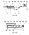
- the clip body has a channel for accommodating a main portion of a hooked end of a wiper arm, said channel comprising an upper surface of a wall and side walls of the clip body, at least one of said side walls having a resiliently deformable wall portion which extends into the channel to engage a main portion of a hooked end of a wiper arm.
- the at least one resiliently deformable wall portion enables the clip to accommodate wiper arms having hooked ends of different widths can provide, at least partially, a necked portion adjacent the outer end of the channel.
- the lug of the plug can act as a back-up, should the other means for retaining the hooked end of the wiper arm in the clip fail for whatever reason.
- the resiliently deformable wall portion at least partially defines a necked portion of the channel adjacent an end thereof.
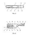
- a plug is connected to the body 2 of the clip 1 by means of a weakened portion 12 of the material from which the clip 1 is moulded, to provide a hinge between the body 2 and plug 11.
- the clip 1 is mounted pivotally upon the pivot element 42 of the assembly 41, as discussed above.
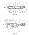
- a second improvement of the clip 111 in accordance with the second embodiment can be more readily seen with references to Figures 8, 11 and 12.
- the clip 111 is adapted to receive a bayonet type end of a wiper arm in an elongate recess 1156 extending into the body 112 between the upper surface 119 and a pair of spaced, hooked end receiving surfaces 113, 114 which are at least partially defined by respective locating recesses 115, 116 on opposed upper and lower sides of a wall 117 of the clip body 112.
- a wiper blade assembly can be pivotally attached to the clip 111 by locating a pivot element thereof in the snap-fit aperture 1118 of the clip body 112.
Landscapes
- Engineering & Computer Science (AREA)
- Mechanical Engineering (AREA)
- Insertion Pins And Rivets (AREA)
- Connection Of Plates (AREA)
- Clamps And Clips (AREA)
Abstract
Description
Claims (34)
- A clip for connecting an end of a wiper arm to a wiper blade assembly, the clip comprising a body defining two or more recesses arranged to receive therein different ends of wiper arms.
- A clip according to claim 1, wherein different ends of wiper arms are receivable in respective ones of the recesses in close tolerance or friction fit therewith.
- A clip according to claim 1 or 2, wherein the recesses are arranged to receive ends of wiper arms of different connection configurations and/or different sizes.
- A clip according to claim 1, 2 or 3, wherein at least one of the recesses is provided with a resiliently deformable tongue member to assist reception of an end of a wiper arm having a bayonet type connecting end in said at least one recess.
- A clip according to claim 4, wherein the recess for receiving a wiper arm having a bayonet type connecting end has an aperture associated therewith for engaging a complementary retaining prong of the wiper arm on reception of the wiper arm connecting end in the recess.
- A clip according to any preceding claim, wherein the two or more recesses comprise two or more spaced surfaces which are arranged to receive thereon respective different sizes of hooked ends of wiper arms.
- A clip according to any preceding claim, wherein the body of the clip includes a pair of spaced surfaces defined by respective locating recesses.
- A clip according to claim 7, wherein the locating recesses are provided on opposed sides of a wall of the clip body.
- A clip according to claim 6 or claim 7 or 8 when dependent thereon, wherein at least one of the receiving surfaces is be provided with a resilient retaining prong which can be engaged within a complementary aperture in the hooked end of a wiper arm fitted to the clip.
- A clip according to claim 9, wherein the resilient retaining prong is engageable within a complementary aperture in the return portion of the hooked end of a wiper arm fitted to the clip.
- A clip according to claim 9 or 10, wherein the retaining prong is resilient, so that it can be disengaged from the complementary aperture, to permit the hooked end of the wiper arm to be detached from the clip, for maintenance purposes or when changing the arm or associated wiper blade assembly.
- A clip according to any preceding claim, wherein the clip body has a channel for accommodating a main portion of a hooked end of a wiper arm, the channel comprising an upper surface of a wall and side walls of the clip body, at least one of the side walls having a resiliently deformable wall portion which extends into the channel to engage a main portion of a hooked end of a wiper arm.
- A clip according to claim 12, wherein the resiliently deformable wall portion at least partially defines a necked portion of the channel adjacent an outer end thereof.
- A clip according to claim 12 or 13, wherein the at least one resiliently deformable wall portion enables the clip to accommodate wiper arms having hooked ends of different widths.
- A clip according to any preceding claim further comprising a plug for effectively closing an otherwise exposed aperture in the clip body after the end of a wiper arm has been fitted thereto.
- A clip according to claim 15, wherein the plug is movable between respective open and closed positions with respect to the aperture.
- A clip according to claim 15 or 16, wherein the plug is movable between respective open and closed positions with respect to the aperture by means of a hinge.
- A clip according to claim 17, wherein the hinge is formed integrally with the clip body and plug.
- A clip according to any of claims 15 to 18, wherein the outer surface of the plug, when in its closed position with respect to the aperture, is shaped so as to provide a generally smooth continuous surface with the outer surface of the adjacent end of the wiper arm, thereby rendering such a combination aerodynamically efficient, as well as being aesthetically pleasing to the eye.
- A clip according to any of claims 15 to 19, wherein the plug, in its closed position, prevents, or at least substantially reduces, the ingress of water and/or dirt particles into the clip body through the otherwise open wiper arm access aperture.
- A clip according to any of claims 15 to 20, wherein the plug is provided with a lug which, with the plug in its closed position with respect to the aperture in the clip body, engages the arcuate surface of the hooked end of a wiper arm fitted to the clip.
- A clip according to any of claims 15 to 21, wherein the lug of the plug acts as a back-up, should the other means for retaining the hooked end of the wiper arm in the clip fail.
- A clip according to any of claims 15 to 21, wherein the lug is used to retain in position the hooked end of a wiper arm fitted to the clip.
- A clip according to claim 21 or claim 22 or 23 when dependent thereon, wherein the lug has a snap-fit aperture formed integrally therewith and arranged such that, when the plug is moved to its closed position, the snap-fit aperture is coincident with another aperture formed in the clip body.
- A clip according to claim 24, wherein the snap-fit aperture is arranged to engage a pin of a wiper arm side connection means located through the other aperture.
- A clip according to claim 24 or 25, wherein the other aperture is larger than the snap-fit aperture.
- A clip for connecting a wiper arm to a wiper blade assembly, the clip comprising a body having an aperture therein for permitting access of the hooked end of a wiper arm to a close tolerance or friction fit surface, wherein the clip also comprises a plug for closing the access aperture, which plug, in its closed position with respect to the aperture, provides an exterior surface which has enhanced aerodynamically efficiently and is aesthetically pleasing to the eye.
- A clip according to claim 27, wherein the plug comprises a lug which, when the plug is in its closed position with respect to the otherwise open aperture, engages the arcuate or other surface of the hooked end of a wiper arm fitted to the clip.
- A clip according to claim 27 or 28, wherein the plug is hinged to the body of the clip.
- A clip according to claim 29, wherein the plug is hinged integrally to the clip body.
- A clip according to any of claims 27 to 30, wherein the clip is formed from a single plastics moulding.
- A clip according to claim 31, wherein the hinge is provided as a weakened portion thereof.
- A clip for connecting a wiper arm to a wiper blade assembly, the clip comprising a body having an aperture therein for permitting access of the hooked end of a wiper arm to a close tolerance or friction fit surface, wherein the clip includes a channel for accommodating a main portion of a hooked end of a wiper arm, the channel comprising an upper surface of a wall and side walls of the clip body, with at least one of the side walls having a resiliently deformable wall portion which extends into the channel to engage a main portion of a hooked end of a wiper arm.
- A clip according to claim 33, wherein the resiliently deformable wall portion at least defines a necked portion of the channel adjacent an end thereof.
Applications Claiming Priority (2)
| Application Number | Priority Date | Filing Date | Title |
|---|---|---|---|
| GB0311960 | 2003-05-23 | ||
| GB0311960A GB0311960D0 (en) | 2003-05-23 | 2003-05-23 | Wiper arm connecting clip |
Publications (2)
| Publication Number | Publication Date |
|---|---|
| EP1479576A2 true EP1479576A2 (en) | 2004-11-24 |
| EP1479576A3 EP1479576A3 (en) | 2005-04-27 |
Family
ID=9958710
Family Applications (1)
| Application Number | Title | Priority Date | Filing Date |
|---|---|---|---|
| EP04253043A Withdrawn EP1479576A3 (en) | 2003-05-23 | 2004-05-24 | Wiper arm connecting clip |
Country Status (2)
| Country | Link |
|---|---|
| EP (1) | EP1479576A3 (en) |
| GB (2) | GB0311960D0 (en) |
Cited By (6)
| Publication number | Priority date | Publication date | Assignee | Title |
|---|---|---|---|---|
| WO2011098959A1 (en) * | 2010-02-09 | 2011-08-18 | Teklas Kaucuk Sanayi Ve Ticaret A.S. | A cap for windscreen wipers |
| EP2360070A1 (en) * | 2010-02-12 | 2011-08-24 | Unipoint Electric MFG. Co., Ltd. | Wiper connector |
| WO2012079866A1 (en) * | 2010-12-13 | 2012-06-21 | Robert Bosch Gmbh | Wiper device |
| WO2012079849A1 (en) * | 2010-12-13 | 2012-06-21 | Robert Bosch Gmbh | Wiper device |
| US8627539B2 (en) * | 2011-12-20 | 2014-01-14 | Dongyang Mechatronics Corp. | Connector device for coupling wiper arm |
| EP2711253A3 (en) * | 2010-11-04 | 2014-08-20 | Trico Products Corporation | Windshield wiper having a coupler with positive locking features |
Families Citing this family (2)
| Publication number | Priority date | Publication date | Assignee | Title |
|---|---|---|---|---|
| DE102007016479A1 (en) * | 2007-04-05 | 2008-10-09 | Robert Bosch Gmbh | connection device |
| FR3046584B1 (en) * | 2016-01-13 | 2018-01-26 | Valeo Systemes D'essuyage | ADAPTER FOR CONNECTING A WIPER BLADE TO A TRAINING ARM |
Family Cites Families (18)
| Publication number | Priority date | Publication date | Assignee | Title |
|---|---|---|---|---|
| BE810611A (en) * | 1973-03-02 | 1974-05-29 | BRUSH FOR VEHICLE WIPER SYSTEMS | |
| DE2817248A1 (en) * | 1978-04-20 | 1979-10-31 | Bosch Gmbh Robert | WIPING DEVICE FOR WINDOWS OF MOTOR VEHICLES |
| EP0141186B1 (en) * | 1983-09-13 | 1987-08-12 | Equipements Automobiles Brevetés PAUL JOURNEE S.A. | Windshield wiper mounting |
| JPS6393651A (en) * | 1986-10-09 | 1988-04-23 | Ichikoh Ind Ltd | Wiper blade mounting construction |
| FR2692537B3 (en) * | 1992-06-23 | 1994-05-27 | Sen Hsiung Cheng | UNIFIED WIPER BLADE SUPPORT CONNECTOR FOR ATTACHING A WIPER BLADE SUPPORT TO A WINDSHIELD WIPER ARM ASSEMBLY. |
| DE4229127C2 (en) * | 1992-09-01 | 2002-11-28 | Teves Gmbh Alfred | Spring part for windscreen wiper systems |
| US5611103A (en) * | 1993-09-10 | 1997-03-18 | Lee; Albert | Windshield wiper frame connector which accomodates different size wiper arms |
| FR2723056B1 (en) * | 1994-07-26 | 1996-09-06 | Valeo Systemes D Essuyage Sa | DEVICE FOR HANGING A WIPER BLADE ON A WIPER ARM |
| FR2736025B1 (en) * | 1995-06-28 | 1997-08-01 | Valeo Systemes Dessuyage | WINDSCREEN WIPER FOR A MOTOR VEHICLE COMPRISING A CONNECTOR PROVIDED WITH AN ARTICULATED HOOD |
| JPH1016722A (en) * | 1996-07-02 | 1998-01-20 | Asmo Co Ltd | Wiper device |
| DE29718379U1 (en) * | 1997-10-16 | 1998-01-02 | Robert Bosch Gmbh, 70469 Stuttgart | windshield wipers |
| US5920950A (en) * | 1997-12-09 | 1999-07-13 | Trico Products Corporation | Wiper blade attachment adapter |
| DE19758245A1 (en) * | 1997-12-30 | 1999-07-08 | Bosch Gmbh Robert | Connecting element for connecting a wiper blade to a wiper arm hook |
| FR2786449B1 (en) * | 1998-11-30 | 2001-02-23 | Valeo Systemes Dessuyage | MOTOR VEHICLE WINDSCREEN WIPER CONNECTOR |
| DE19941499B4 (en) * | 1999-08-31 | 2018-08-16 | Robert Bosch Gmbh | Connector for connecting a wiper blade to a wiper arm |
| FR2822119B3 (en) * | 2001-03-15 | 2003-02-14 | Shu Lan Ku | WIPER BLADE CONNECTION AND WIPER ASSEMBLY |
| US6640380B2 (en) * | 2001-10-05 | 2003-11-04 | Pylon Manufacturing Corporation | Wiper blade connector |
| FR2830823B1 (en) * | 2001-10-15 | 2004-02-27 | Valeo Systemes Dessuyage | MOTOR VEHICLE WIPER WITH SAFETY CLASP |
-
2003
- 2003-05-23 GB GB0311960A patent/GB0311960D0/en not_active Ceased
-
2004
- 2004-05-24 GB GB0411540A patent/GB2402609A/en not_active Withdrawn
- 2004-05-24 EP EP04253043A patent/EP1479576A3/en not_active Withdrawn
Cited By (13)
| Publication number | Priority date | Publication date | Assignee | Title |
|---|---|---|---|---|
| WO2011098959A1 (en) * | 2010-02-09 | 2011-08-18 | Teklas Kaucuk Sanayi Ve Ticaret A.S. | A cap for windscreen wipers |
| EP2360070A1 (en) * | 2010-02-12 | 2011-08-24 | Unipoint Electric MFG. Co., Ltd. | Wiper connector |
| EP2711253A3 (en) * | 2010-11-04 | 2014-08-20 | Trico Products Corporation | Windshield wiper having a coupler with positive locking features |
| US9731685B2 (en) | 2010-11-04 | 2017-08-15 | Trico Products Corporation | Windshield wiper having a coupler with positive locking features |
| EP2635467A4 (en) * | 2010-11-04 | 2015-11-18 | Trico Products Corp | WINDSHIELD WIPER HAVING A COUPLER HAVING SELF-LINKING CHARACTERISTICS |
| US8881338B2 (en) | 2010-11-04 | 2014-11-11 | Trico Products Corporation | Windshield wiper having a coupler with positive locking features |
| WO2012079849A1 (en) * | 2010-12-13 | 2012-06-21 | Robert Bosch Gmbh | Wiper device |
| CN103282245A (en) * | 2010-12-13 | 2013-09-04 | 罗伯特·博世有限公司 | Wiper device |
| US9302652B2 (en) | 2010-12-13 | 2016-04-05 | Robert Bosch Gmbh | Wiper device |
| RU2601501C2 (en) * | 2010-12-13 | 2016-11-10 | Роберт Бош Гмбх | Wiper |
| WO2012079866A1 (en) * | 2010-12-13 | 2012-06-21 | Robert Bosch Gmbh | Wiper device |
| DE102010062928B4 (en) | 2010-12-13 | 2023-09-07 | Robert Bosch Gmbh | wiper device |
| US8627539B2 (en) * | 2011-12-20 | 2014-01-14 | Dongyang Mechatronics Corp. | Connector device for coupling wiper arm |
Also Published As
| Publication number | Publication date |
|---|---|
| EP1479576A3 (en) | 2005-04-27 |
| GB2402609A (en) | 2004-12-15 |
| GB0411540D0 (en) | 2004-06-23 |
| GB0311960D0 (en) | 2003-06-25 |
Similar Documents
| Publication | Publication Date | Title |
|---|---|---|
| US9365189B2 (en) | Windscreen wiper device | |
| GB2324237A (en) | Wiper blade assembly | |
| US9738261B2 (en) | Windscreen wiper device | |
| JP5335133B2 (en) | Connecting device for pivotally coupling a coupling element rigidly coupled to a wiper arm | |
| US6758777B2 (en) | Snap-fit chain guide with locking connector arrangement | |
| KR101447584B1 (en) | Connection device for the articulated connection of a wiper blade to a wiper arm | |
| KR20050085129A (en) | Device for detachably linking a wiper blade with a driven wiper arm | |
| JP5009999B2 (en) | Connecting member for pivotally connecting the wiper blade and the wiper arm | |
| US5920950A (en) | Wiper blade attachment adapter | |
| US8308205B2 (en) | Toggle latch | |
| US20120000028A1 (en) | Connecting device for a wiper arm | |
| KR20110039390A (en) | Device for articulating wiper blades on wiper arms of vehicle windshield wipers | |
| US20030173102A1 (en) | Protector for wire harness | |
| EP1479576A2 (en) | Wiper arm connecting clip | |
| KR20080011166A (en) | wiper blade | |
| US6701584B2 (en) | Zipper guard | |
| CA1166407A (en) | Multi - purpose connector | |
| US6065180A (en) | Releaseable wiper arm-wiper blade connection on a vehicle windshield wiper | |
| EP0969993A1 (en) | Motor vehicle wiper | |
| CN106347310B (en) | Adapter for connecting a windscreen wiper blade to a drive arm | |
| GB2119637A (en) | Connectors for pivotally connecting wiper arms to wiper blades | |
| KR950014783B1 (en) | Pivot Joint of Windscreen Wiper | |
| US20080163446A1 (en) | Windshield Wiper Mechanism Connector for Mounting the End of an Arm Sideways Onto a Wiper Blade Unit | |
| CN211731324U (en) | Windscreen wiper with adaptable brush joint | |
| KR200182592Y1 (en) | A plastic spade for preventing tip |
Legal Events
| Date | Code | Title | Description |
|---|---|---|---|
| PUAI | Public reference made under article 153(3) epc to a published international application that has entered the european phase |
Free format text: ORIGINAL CODE: 0009012 |
|
| AK | Designated contracting states |
Kind code of ref document: A2 Designated state(s): AT BE BG CH CY CZ DE DK EE ES FI FR GB GR HU IE IT LI LU MC NL PL PT RO SE SI SK TR |
|
| AX | Request for extension of the european patent |
Extension state: AL HR LT LV MK |
|
| PUAL | Search report despatched |
Free format text: ORIGINAL CODE: 0009013 |
|
| AK | Designated contracting states |
Kind code of ref document: A3 Designated state(s): AT BE BG CH CY CZ DE DK EE ES FI FR GB GR HU IE IT LI LU MC NL PL PT RO SE SI SK TR |
|
| AX | Request for extension of the european patent |
Extension state: AL HR LT LV MK |
|
| 17P | Request for examination filed |
Effective date: 20051021 |
|
| AKX | Designation fees paid |
Designated state(s): AT BE BG CH CY CZ DE DK EE ES FI FR GB GR HU IE IT LI LU MC NL PL PT RO SE SI SK TR |
|
| STAA | Information on the status of an ep patent application or granted ep patent |
Free format text: STATUS: THE APPLICATION IS DEEMED TO BE WITHDRAWN |
|
| 18D | Application deemed to be withdrawn |
Effective date: 20061201 |