EP1479566A1 - Anchoring device with a mechanical fuse - Google Patents
Anchoring device with a mechanical fuse Download PDFInfo
- Publication number
- EP1479566A1 EP1479566A1 EP04380110A EP04380110A EP1479566A1 EP 1479566 A1 EP1479566 A1 EP 1479566A1 EP 04380110 A EP04380110 A EP 04380110A EP 04380110 A EP04380110 A EP 04380110A EP 1479566 A1 EP1479566 A1 EP 1479566A1
- Authority
- EP
- European Patent Office
- Prior art keywords
- peripheral
- divider
- washer
- seat
- assembled
- Prior art date
- Legal status (The legal status is an assumption and is not a legal conclusion. Google has not performed a legal analysis and makes no representation as to the accuracy of the status listed.)
- Granted
Links
- 238000004873 anchoring Methods 0.000 title claims abstract description 12
- 230000002093 peripheral effect Effects 0.000 claims abstract description 22
- 230000008719 thickening Effects 0.000 claims description 4
- 230000000717 retained effect Effects 0.000 claims 1
- 230000000284 resting effect Effects 0.000 description 2
- 208000027418 Wounds and injury Diseases 0.000 description 1
- 230000006378 damage Effects 0.000 description 1
- 230000000694 effects Effects 0.000 description 1
- 230000005489 elastic deformation Effects 0.000 description 1
- 208000014674 injury Diseases 0.000 description 1
Images
Classifications
-
- B—PERFORMING OPERATIONS; TRANSPORTING
- B60—VEHICLES IN GENERAL
- B60R—VEHICLES, VEHICLE FITTINGS, OR VEHICLE PARTS, NOT OTHERWISE PROVIDED FOR
- B60R13/00—Elements for body-finishing, identifying, or decorating; Arrangements or adaptations for advertising purposes
- B60R13/02—Internal Trim mouldings ; Internal Ledges; Wall liners for passenger compartments; Roof liners
- B60R13/0206—Arrangements of fasteners and clips specially adapted for attaching inner vehicle liners or mouldings
-
- B—PERFORMING OPERATIONS; TRANSPORTING
- B60—VEHICLES IN GENERAL
- B60R—VEHICLES, VEHICLE FITTINGS, OR VEHICLE PARTS, NOT OTHERWISE PROVIDED FOR
- B60R11/00—Arrangements for holding or mounting articles, not otherwise provided for
-
- B—PERFORMING OPERATIONS; TRANSPORTING
- B60—VEHICLES IN GENERAL
- B60R—VEHICLES, VEHICLE FITTINGS, OR VEHICLE PARTS, NOT OTHERWISE PROVIDED FOR
- B60R11/00—Arrangements for holding or mounting articles, not otherwise provided for
- B60R11/02—Arrangements for holding or mounting articles, not otherwise provided for for radio sets, television sets, telephones, or the like; Arrangement of controls thereof
-
- B—PERFORMING OPERATIONS; TRANSPORTING
- B60—VEHICLES IN GENERAL
- B60R—VEHICLES, VEHICLE FITTINGS, OR VEHICLE PARTS, NOT OTHERWISE PROVIDED FOR
- B60R11/00—Arrangements for holding or mounting articles, not otherwise provided for
- B60R2011/0001—Arrangements for holding or mounting articles, not otherwise provided for characterised by position
- B60R2011/0003—Arrangements for holding or mounting articles, not otherwise provided for characterised by position inside the vehicle
- B60R2011/0005—Dashboard
-
- B—PERFORMING OPERATIONS; TRANSPORTING
- B60—VEHICLES IN GENERAL
- B60R—VEHICLES, VEHICLE FITTINGS, OR VEHICLE PARTS, NOT OTHERWISE PROVIDED FOR
- B60R11/00—Arrangements for holding or mounting articles, not otherwise provided for
- B60R2011/0042—Arrangements for holding or mounting articles, not otherwise provided for characterised by mounting means
- B60R2011/0049—Arrangements for holding or mounting articles, not otherwise provided for characterised by mounting means for non integrated articles
- B60R2011/005—Connection with the vehicle part
- B60R2011/0052—Connection with the vehicle part using screws, bolts, rivets or the like
Definitions
- the present Utility Model refers to an anchoring device with a mechanical fuse, especially applicable in the assembly of components inside vehicle interiors.
- the official approval standard sets maximum levels for the projections in each area of the dashboard. This produces an incompatibility in the use of the rotational manual actuation controls with the tests required for the official approval of the vehicle incorporating them since, in the position they are in, they surpass the maximum levels permitted.
- the climate control panel is assembled outside of the possible impact area, or else panels are designed without said projections.
- the present invention has as an object an anchoring device with a mechanical fuse, which allows assembling certain components with projecting elements on the dashboard, without said elements affecting the safety standards, and all this is a result of the fact that the anchoring devices used allow for the assembled components to withdraw or move towards a withdrawn position when a certain force is applied thereon, for example when they are struck, such that the projections they may include do not entail a risk for the occupants of the vehicle.
- the components are fixed inside the vehicle interior, for example on the dashboard, by means of mechanical fuses including lock screws and, under normal use conditions, the components are fixed to the dashboard or area where they are assembled with said lock screws, as in standard anchoring systems, whereas in the event of being struck, for example due to an accident, beyond a certain magnitude, a movement of the component towards the interior of the dashboard occurs, using an available space provided for that purpose, thus eliminating any risk of injuries due to the projections of the mentioned components.
- an anchoring device consisting of a tubular divider and a spring lock washer.
- the tubular divider is of a stiff nature and is intended to be introduced through holes of the component to be assembled, being of a length exceeding the depth of these holes and being finished off at one of its end sections with a peripheral flange.
- the lock screws for fixing the component to the dashboard or assembly area of the vehicle pass through the tubular dividers.
- the lock washer is tightly assembled on the outer surface of the tubular divider at a distance from the peripheral flange of said divider approximately equal to the depth of the holes of the component through which the divider is introduced.
- the tubular divider is externally provided with a peripheral seat for the spring lock washer.
- This seat is separated from the peripheral flange by a distance approximately equal to the depth of the holes of the component to be fixed.
- the seat has locking means preventing the free slipping of the washer, such that to remove it from the seat and to overcome the locking means, it is necessary to elastically deform or expand the washer, to which end it will be necessary to apply a certain force.
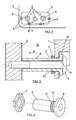
- FIG. 1 shows a front elevational view of a climate control panel referred to with number 1, which is assembled on a certain area of the dashboard 2 of a vehicle.
- This climate control panel includes a series of rotational controls 3 which, as is the usual case, have a diametric handle 4 which substantial projects from the surface of the panel 1 and dashboard 2.
- the fixing of the panel 1 to the dashboard 2 is carried out by means of screws 5.
- the screws 5 pass through an anchoring device made up of a tubular divider 6 and a spring lock washer 7.
- the tubular divider 6 is introduced through the holes 8 of the panel 1 and is finished off at one of its end sections with a peripheral flange 9 externally resting on the area surrounding said hole.
- the divider 6 is of a length that greatly exceeds the depth of the holes 8, resting on the area of the dashboard 2 in which it is assembled at its end section.
- the washer 7 is tightly assembled on the outer surface of the divider 6 and is separated from the peripheral flange 9 of the divider by a distance approximately equal to the depth of the holes 8.
- the divider 6 has a peripheral seat 10 for the washer 7 on its outer surface.
- this seat constituted of a peripheral recess, has locking means preventing the free slipping of the washer 7, said means possibly being constituted of a peripheral rib or thickening 11 limiting the seat 10 on the side farthest from the flange 9.
- the seat 10 will be situated at a distance from the flange 9 approximately equal to the depth of the boreholes 8.
- the washer 7 will be assembled on the seat 10 and fixed thereto due to its resilient nature, and it can only overcome and move over the thickening 11 by means of its elastic expansion or deformation when it is pushed in the direction of the arrow A with a force exceeding a preset value.
- the lock screw 5 for fixing the panel 1 to the dashboard 2 is introduced through the divider 6.
- the panel 1 in a normal situation the panel 1 is fixed solidly to the dashboard 2 by means of lock screws 5.
- the panel 1 In the event that the panel 1 is struck, for example due to an accident, if it exceeds the preset value, it will cause the movement of the washer 7 in direction A, and with it the movement of said panel 1 towards the interior of the dashboard, in a space 12 provided for that purpose, such that both the panel 1 and the controls 3 withdraw towards the interior of the dashboard and do not constitute elements of risk for the passengers.
- the washer 7 can adopt an approximately polygonal configuration, as shown in Figure 3.
- the tubular divider 6 is of a uniform section along the length thereof, except for the peripheral thickening 11 and seat 10.
- the tubular divider 6 will be introduced through the hole 8, and then the washer 7 will be assembled, overcoming the peripheral rib or projection 11 by means of its elastic deformation. Then the screws 5 are introduced, which will be screwed into the holes of the dashboard.
Landscapes
- Engineering & Computer Science (AREA)
- Mechanical Engineering (AREA)
- Body Structure For Vehicles (AREA)
- Fuses (AREA)
- Coupling Device And Connection With Printed Circuit (AREA)
- Mechanical Operated Clutches (AREA)
- Fittings On The Vehicle Exterior For Carrying Loads, And Devices For Holding Or Mounting Articles (AREA)
- Dowels (AREA)
Abstract
Description
- The present Utility Model refers to an anchoring device with a mechanical fuse, especially applicable in the assembly of components inside vehicle interiors.
- It is known that for passive safety reasons, there are strict standards governing the elements projecting inside the vehicle interior with regard to size and shape thereof. The management controls of the climate control system are one of the critical elements because the necessity of being able to turn them manually makes it necessary for them to project from the plane of the remaining controls.
- For ensuring safety inside the vehicle interior, the official approval standard sets maximum levels for the projections in each area of the dashboard. This produces an incompatibility in the use of the rotational manual actuation controls with the tests required for the official approval of the vehicle incorporating them since, in the position they are in, they surpass the maximum levels permitted. Usually to prevent this incompatibility, either the climate control panel is assembled outside of the possible impact area, or else panels are designed without said projections.
- The present invention has as an object an anchoring device with a mechanical fuse, which allows assembling certain components with projecting elements on the dashboard, without said elements affecting the safety standards, and all this is a result of the fact that the anchoring devices used allow for the assembled components to withdraw or move towards a withdrawn position when a certain force is applied thereon, for example when they are struck, such that the projections they may include do not entail a risk for the occupants of the vehicle.
- With this system, the components are fixed inside the vehicle interior, for example on the dashboard, by means of mechanical fuses including lock screws and, under normal use conditions, the components are fixed to the dashboard or area where they are assembled with said lock screws, as in standard anchoring systems, whereas in the event of being struck, for example due to an accident, beyond a certain magnitude, a movement of the component towards the interior of the dashboard occurs, using an available space provided for that purpose, thus eliminating any risk of injuries due to the projections of the mentioned components.
- The indicated effects and advantages are achieved, according to the present invention, by means of an anchoring device consisting of a tubular divider and a spring lock washer. The tubular divider is of a stiff nature and is intended to be introduced through holes of the component to be assembled, being of a length exceeding the depth of these holes and being finished off at one of its end sections with a peripheral flange. The lock screws for fixing the component to the dashboard or assembly area of the vehicle pass through the tubular dividers. The lock washer is tightly assembled on the outer surface of the tubular divider at a distance from the peripheral flange of said divider approximately equal to the depth of the holes of the component through which the divider is introduced.
- According to another feature of the invention, the tubular divider is externally provided with a peripheral seat for the spring lock washer. This seat is separated from the peripheral flange by a distance approximately equal to the depth of the holes of the component to be fixed. Furthermore, the seat has locking means preventing the free slipping of the washer, such that to remove it from the seat and to overcome the locking means, it is necessary to elastically deform or expand the washer, to which end it will be necessary to apply a certain force.
- The features of the anchoring device of the invention are set forth below with greater detail in the following description with the aid of the attached drawings which show a non-limiting embodiment.
- In the drawings:
- Figure 1 shows a front elevational view of a climate control panel assembled on the dashboard of a vehicle.
- Figure 2 shows an enlarged, partial sectional view of the climate control panel assembled on the dashboard, taken along the II-II section line.
- Figure 3 shows a perspective view of the components of the anchoring device of the invention.
-
- Figure 1 shows a front elevational view of a climate control panel referred to with number 1, which is assembled on a certain area of the
dashboard 2 of a vehicle. This climate control panel includes a series of rotational controls 3 which, as is the usual case, have adiametric handle 4 which substantial projects from the surface of the panel 1 anddashboard 2. - The fixing of the panel 1 to the
dashboard 2 is carried out by means ofscrews 5. - According to the invention, the
screws 5 pass through an anchoring device made up of atubular divider 6 and aspring lock washer 7. - The
tubular divider 6 is introduced through theholes 8 of the panel 1 and is finished off at one of its end sections with aperipheral flange 9 externally resting on the area surrounding said hole. As can be seen in Figure 2, thedivider 6 is of a length that greatly exceeds the depth of theholes 8, resting on the area of thedashboard 2 in which it is assembled at its end section. - The
washer 7 is tightly assembled on the outer surface of thedivider 6 and is separated from theperipheral flange 9 of the divider by a distance approximately equal to the depth of theholes 8. - The
divider 6 has aperipheral seat 10 for thewasher 7 on its outer surface. Preferably this seat, constituted of a peripheral recess, has locking means preventing the free slipping of thewasher 7, said means possibly being constituted of a peripheral rib or thickening 11 limiting theseat 10 on the side farthest from theflange 9. - The
seat 10 will be situated at a distance from theflange 9 approximately equal to the depth of theboreholes 8. - The
washer 7 will be assembled on theseat 10 and fixed thereto due to its resilient nature, and it can only overcome and move over thethickening 11 by means of its elastic expansion or deformation when it is pushed in the direction of the arrow A with a force exceeding a preset value. - The
lock screw 5 for fixing the panel 1 to thedashboard 2 is introduced through thedivider 6. - With the constitution discussed, in a normal situation the panel 1 is fixed solidly to the
dashboard 2 by means oflock screws 5. In the event that the panel 1 is struck, for example due to an accident, if it exceeds the preset value, it will cause the movement of thewasher 7 in direction A, and with it the movement of said panel 1 towards the interior of the dashboard, in aspace 12 provided for that purpose, such that both the panel 1 and the controls 3 withdraw towards the interior of the dashboard and do not constitute elements of risk for the passengers. - The
washer 7 can adopt an approximately polygonal configuration, as shown in Figure 3. - The
tubular divider 6 is of a uniform section along the length thereof, except for theperipheral thickening 11 andseat 10. - For the assembly of the anchoring devices in the panel 1, the
tubular divider 6 will be introduced through thehole 8, and then thewasher 7 will be assembled, overcoming the peripheral rib orprojection 11 by means of its elastic deformation. Then thescrews 5 are introduced, which will be screwed into the holes of the dashboard.
Claims (3)
- An anchoring device with a mechanical fuse, especially applicable to the assembly of components (1) inside vehicle interiors, characterized in that it is made up of a tubular divider (6) intended for being introduced through holes (8) of the component to be assembled, and through which holes lock screws (5) for fixing said component pass, and of a spring lock washer (7) tightly assembled on the outer surface of the tubular divider (6); which divider is of a length exceeding the depth of the holes (8) of the component to be assembled, of uniform section and finished off at one of its end sections with a peripheral flange (9), externally provided with a peripheral seat (10) for the spring lock washer (7), which is separated from the peripheral flange (9) by a distance approximately equal to the depth of the holes (8) of the component to be fixed and is provided with locking means (11) preventing the free slipping of the washer out of said seat and which can be overcome by said washer by means of elastic expansion thereof; and which spring lock washer defines a peripheral stop on the tubular divider (6) between which stop and the peripheral flange (9) of said divider, the component to be assembled is retained.
- A device according to claim 1, characterized in that the peripheral seat for the lock washer (7) consists of a peripheral groove (10) in which said washer is partially housed.
- A device according to claims 1 or 2, characterized in that the locking means of the peripheral seat (10) consist of a peripheral thickening (11) of the tubular divider (6) which limits said seat on the side farthest from the peripheral flange (9) of the divider.
Applications Claiming Priority (2)
| Application Number | Priority Date | Filing Date | Title |
|---|---|---|---|
| ES200301229U ES1054767Y (en) | 2003-05-20 | 2003-05-20 | ANCHORAGE DEVICE WITH MECHANICAL FUSE |
| ES200301229U | 2003-05-20 |
Publications (2)
| Publication Number | Publication Date |
|---|---|
| EP1479566A1 true EP1479566A1 (en) | 2004-11-24 |
| EP1479566B1 EP1479566B1 (en) | 2007-07-25 |
Family
ID=27838615
Family Applications (1)
| Application Number | Title | Priority Date | Filing Date |
|---|---|---|---|
| EP04380110A Expired - Lifetime EP1479566B1 (en) | 2003-05-20 | 2004-05-18 | Anchoring device with a mechanical fuse |
Country Status (4)
| Country | Link |
|---|---|
| EP (1) | EP1479566B1 (en) |
| AT (1) | ATE367950T1 (en) |
| DE (1) | DE602004007719T2 (en) |
| ES (2) | ES1054767Y (en) |
Cited By (1)
| Publication number | Priority date | Publication date | Assignee | Title |
|---|---|---|---|---|
| GB2582853A (en) * | 2019-01-18 | 2020-10-07 | Porsche Ag | Inside door opener arrangement |
Citations (4)
| Publication number | Priority date | Publication date | Assignee | Title |
|---|---|---|---|---|
| US4760495A (en) * | 1987-04-16 | 1988-07-26 | Prime Computer Inc. | Stand-off device |
| US4906152A (en) * | 1987-06-30 | 1990-03-06 | Nifco, Inc. | Screw retainer |
| US5135341A (en) * | 1990-11-17 | 1992-08-04 | Blaupunkt-Werke Gmbh | Device for fastening an electronic equipment to a mounting wall |
| DE19816053A1 (en) * | 1997-04-18 | 1998-10-22 | Volkswagen Ag | Bracket fastener for engine bearers etc. |
-
2003
- 2003-05-20 ES ES200301229U patent/ES1054767Y/en not_active Expired - Fee Related
-
2004
- 2004-05-18 AT AT04380110T patent/ATE367950T1/en not_active IP Right Cessation
- 2004-05-18 ES ES04380110T patent/ES2287675T3/en not_active Expired - Lifetime
- 2004-05-18 EP EP04380110A patent/EP1479566B1/en not_active Expired - Lifetime
- 2004-05-18 DE DE602004007719T patent/DE602004007719T2/en not_active Expired - Lifetime
Patent Citations (4)
| Publication number | Priority date | Publication date | Assignee | Title |
|---|---|---|---|---|
| US4760495A (en) * | 1987-04-16 | 1988-07-26 | Prime Computer Inc. | Stand-off device |
| US4906152A (en) * | 1987-06-30 | 1990-03-06 | Nifco, Inc. | Screw retainer |
| US5135341A (en) * | 1990-11-17 | 1992-08-04 | Blaupunkt-Werke Gmbh | Device for fastening an electronic equipment to a mounting wall |
| DE19816053A1 (en) * | 1997-04-18 | 1998-10-22 | Volkswagen Ag | Bracket fastener for engine bearers etc. |
Cited By (3)
| Publication number | Priority date | Publication date | Assignee | Title |
|---|---|---|---|---|
| GB2582853A (en) * | 2019-01-18 | 2020-10-07 | Porsche Ag | Inside door opener arrangement |
| GB2582853B (en) * | 2019-01-18 | 2021-12-22 | Porsche Ag | Inside door opener arrangement |
| US11674337B2 (en) | 2019-01-18 | 2023-06-13 | Dr. Ing. H. C. F Porsche Ag | Inside door opener arrangement |
Also Published As
| Publication number | Publication date |
|---|---|
| DE602004007719T2 (en) | 2008-04-30 |
| ES1054767U (en) | 2003-08-16 |
| DE602004007719D1 (en) | 2007-09-06 |
| EP1479566B1 (en) | 2007-07-25 |
| ATE367950T1 (en) | 2007-08-15 |
| ES2287675T3 (en) | 2007-12-16 |
| ES1054767Y (en) | 2003-12-01 |
Similar Documents
| Publication | Publication Date | Title |
|---|---|---|
| US7832693B2 (en) | Fastener | |
| CN104203660B (en) | Pedestrian protection for motor vehicles | |
| CN111051180B (en) | Adjustable steering column for a motor vehicle comprising an energy absorbing device | |
| WO2018024405A1 (en) | Door handle having a movable emergency opening element | |
| US20120222360A1 (en) | Collapsible door trim pull handle | |
| US11248400B2 (en) | Door handle device for a door of a motor vehicle, door, and motor vehicle | |
| US8388059B2 (en) | Actuating means for a crash-active head restraint | |
| EP1479566B1 (en) | Anchoring device with a mechanical fuse | |
| KR20170021996A (en) | A door latch link structure for preventing door opening | |
| US10676970B2 (en) | Protection block for vehicle door lock | |
| US20090001735A1 (en) | Mechanism for Securing the Handle of a Door or Window | |
| JP4401708B2 (en) | Hood latch control cable holding device | |
| DE102010001449A1 (en) | Centre console for motor car, has fastening dome movable relative to each other in x- and z-direction of motor car, and tab for accommodating attachment unit, where fastening dome and console are formed as one-piece | |
| EP2318722B1 (en) | Fastening device and method for fastening an element in a key-hole shaped cut-out of a wall | |
| DE102007042765A1 (en) | Push button/rotary switch/rotating actuator for commercial motor vehicle, has lining or system panel of passenger cabin accommodated in actuator, where actuator is movable from operating position to sinking position by applying force | |
| WO2014026658A1 (en) | Locking mechanism for a roll cover | |
| JP2014065406A (en) | Fitting structure of pull-handle | |
| JP4162791B2 (en) | Mounting structure for on-vehicle equipment | |
| CN213298493U (en) | Fixing assemblies and associated interior elements for fixing at least two parts to each other | |
| KR101806618B1 (en) | Outside handle of vehicle | |
| EP2842817A1 (en) | Steering lock device | |
| KR101718805B1 (en) | Door handle assembly of a vehicle door equipped with acceleration sensors | |
| KR100657668B1 (en) | Car Armrests | |
| DE202004019805U1 (en) | sensor mat | |
| US7123885B2 (en) | Housing that automatically locks into a mounting structure |
Legal Events
| Date | Code | Title | Description |
|---|---|---|---|
| PUAI | Public reference made under article 153(3) epc to a published international application that has entered the european phase |
Free format text: ORIGINAL CODE: 0009012 |
|
| AK | Designated contracting states |
Kind code of ref document: A1 Designated state(s): AT BE BG CH CY CZ DE DK EE ES FI FR GB GR HU IE IT LI LU MC NL PL PT RO SE SI SK TR |
|
| AX | Request for extension of the european patent |
Extension state: AL HR LT LV MK |
|
| 17P | Request for examination filed |
Effective date: 20050317 |
|
| AKX | Designation fees paid |
Designated state(s): AT BE BG CH CY CZ DE DK EE ES FI FR GB GR HU IE IT LI LU MC NL PL PT RO SE SI SK TR |
|
| GRAP | Despatch of communication of intention to grant a patent |
Free format text: ORIGINAL CODE: EPIDOSNIGR1 |
|
| GRAS | Grant fee paid |
Free format text: ORIGINAL CODE: EPIDOSNIGR3 |
|
| GRAA | (expected) grant |
Free format text: ORIGINAL CODE: 0009210 |
|
| AK | Designated contracting states |
Kind code of ref document: B1 Designated state(s): AT BE BG CH CY CZ DE DK EE ES FI FR GB GR HU IE IT LI LU MC NL PL PT RO SE SI SK TR |
|
| REG | Reference to a national code |
Ref country code: GB Ref legal event code: FG4D |
|
| REG | Reference to a national code |
Ref country code: CH Ref legal event code: EP |
|
| REG | Reference to a national code |
Ref country code: IE Ref legal event code: FG4D |
|
| REF | Corresponds to: |
Ref document number: 602004007719 Country of ref document: DE Date of ref document: 20070906 Kind code of ref document: P |
|
| ET | Fr: translation filed | ||
| REG | Reference to a national code |
Ref country code: ES Ref legal event code: FG2A Ref document number: 2287675 Country of ref document: ES Kind code of ref document: T3 |
|
| PG25 | Lapsed in a contracting state [announced via postgrant information from national office to epo] |
Ref country code: NL Free format text: LAPSE BECAUSE OF FAILURE TO SUBMIT A TRANSLATION OF THE DESCRIPTION OR TO PAY THE FEE WITHIN THE PRESCRIBED TIME-LIMIT Effective date: 20070725 Ref country code: BG Free format text: LAPSE BECAUSE OF FAILURE TO SUBMIT A TRANSLATION OF THE DESCRIPTION OR TO PAY THE FEE WITHIN THE PRESCRIBED TIME-LIMIT Effective date: 20071025 Ref country code: PT Free format text: LAPSE BECAUSE OF FAILURE TO SUBMIT A TRANSLATION OF THE DESCRIPTION OR TO PAY THE FEE WITHIN THE PRESCRIBED TIME-LIMIT Effective date: 20071226 Ref country code: FI Free format text: LAPSE BECAUSE OF FAILURE TO SUBMIT A TRANSLATION OF THE DESCRIPTION OR TO PAY THE FEE WITHIN THE PRESCRIBED TIME-LIMIT Effective date: 20070725 |
|
| REG | Reference to a national code |
Ref country code: CH Ref legal event code: PL |
|
| NLV1 | Nl: lapsed or annulled due to failure to fulfill the requirements of art. 29p and 29m of the patents act | ||
| PG25 | Lapsed in a contracting state [announced via postgrant information from national office to epo] |
Ref country code: AT Free format text: LAPSE BECAUSE OF FAILURE TO SUBMIT A TRANSLATION OF THE DESCRIPTION OR TO PAY THE FEE WITHIN THE PRESCRIBED TIME-LIMIT Effective date: 20070725 Ref country code: PL Free format text: LAPSE BECAUSE OF FAILURE TO SUBMIT A TRANSLATION OF THE DESCRIPTION OR TO PAY THE FEE WITHIN THE PRESCRIBED TIME-LIMIT Effective date: 20070725 Ref country code: LI Free format text: LAPSE BECAUSE OF FAILURE TO SUBMIT A TRANSLATION OF THE DESCRIPTION OR TO PAY THE FEE WITHIN THE PRESCRIBED TIME-LIMIT Effective date: 20070725 Ref country code: CH Free format text: LAPSE BECAUSE OF FAILURE TO SUBMIT A TRANSLATION OF THE DESCRIPTION OR TO PAY THE FEE WITHIN THE PRESCRIBED TIME-LIMIT Effective date: 20070725 |
|
| PG25 | Lapsed in a contracting state [announced via postgrant information from national office to epo] |
Ref country code: BE Free format text: LAPSE BECAUSE OF FAILURE TO SUBMIT A TRANSLATION OF THE DESCRIPTION OR TO PAY THE FEE WITHIN THE PRESCRIBED TIME-LIMIT Effective date: 20070725 |
|
| PG25 | Lapsed in a contracting state [announced via postgrant information from national office to epo] |
Ref country code: GR Free format text: LAPSE BECAUSE OF FAILURE TO SUBMIT A TRANSLATION OF THE DESCRIPTION OR TO PAY THE FEE WITHIN THE PRESCRIBED TIME-LIMIT Effective date: 20071026 Ref country code: DK Free format text: LAPSE BECAUSE OF FAILURE TO SUBMIT A TRANSLATION OF THE DESCRIPTION OR TO PAY THE FEE WITHIN THE PRESCRIBED TIME-LIMIT Effective date: 20070725 |
|
| PG25 | Lapsed in a contracting state [announced via postgrant information from national office to epo] |
Ref country code: CZ Free format text: LAPSE BECAUSE OF FAILURE TO SUBMIT A TRANSLATION OF THE DESCRIPTION OR TO PAY THE FEE WITHIN THE PRESCRIBED TIME-LIMIT Effective date: 20070725 Ref country code: SK Free format text: LAPSE BECAUSE OF FAILURE TO SUBMIT A TRANSLATION OF THE DESCRIPTION OR TO PAY THE FEE WITHIN THE PRESCRIBED TIME-LIMIT Effective date: 20070725 |
|
| PLBE | No opposition filed within time limit |
Free format text: ORIGINAL CODE: 0009261 |
|
| STAA | Information on the status of an ep patent application or granted ep patent |
Free format text: STATUS: NO OPPOSITION FILED WITHIN TIME LIMIT |
|
| PG25 | Lapsed in a contracting state [announced via postgrant information from national office to epo] |
Ref country code: SE Free format text: LAPSE BECAUSE OF FAILURE TO SUBMIT A TRANSLATION OF THE DESCRIPTION OR TO PAY THE FEE WITHIN THE PRESCRIBED TIME-LIMIT Effective date: 20071025 Ref country code: RO Free format text: LAPSE BECAUSE OF FAILURE TO SUBMIT A TRANSLATION OF THE DESCRIPTION OR TO PAY THE FEE WITHIN THE PRESCRIBED TIME-LIMIT Effective date: 20070725 |
|
| 26N | No opposition filed |
Effective date: 20080428 |
|
| PG25 | Lapsed in a contracting state [announced via postgrant information from national office to epo] |
Ref country code: MC Free format text: LAPSE BECAUSE OF NON-PAYMENT OF DUE FEES Effective date: 20080531 |
|
| PG25 | Lapsed in a contracting state [announced via postgrant information from national office to epo] |
Ref country code: EE Free format text: LAPSE BECAUSE OF FAILURE TO SUBMIT A TRANSLATION OF THE DESCRIPTION OR TO PAY THE FEE WITHIN THE PRESCRIBED TIME-LIMIT Effective date: 20070725 Ref country code: IE Free format text: LAPSE BECAUSE OF NON-PAYMENT OF DUE FEES Effective date: 20080519 |
|
| PG25 | Lapsed in a contracting state [announced via postgrant information from national office to epo] |
Ref country code: SI Free format text: LAPSE BECAUSE OF FAILURE TO SUBMIT A TRANSLATION OF THE DESCRIPTION OR TO PAY THE FEE WITHIN THE PRESCRIBED TIME-LIMIT Effective date: 20070725 |
|
| PG25 | Lapsed in a contracting state [announced via postgrant information from national office to epo] |
Ref country code: CY Free format text: LAPSE BECAUSE OF FAILURE TO SUBMIT A TRANSLATION OF THE DESCRIPTION OR TO PAY THE FEE WITHIN THE PRESCRIBED TIME-LIMIT Effective date: 20070725 |
|
| PG25 | Lapsed in a contracting state [announced via postgrant information from national office to epo] |
Ref country code: LU Free format text: LAPSE BECAUSE OF NON-PAYMENT OF DUE FEES Effective date: 20080518 Ref country code: HU Free format text: LAPSE BECAUSE OF FAILURE TO SUBMIT A TRANSLATION OF THE DESCRIPTION OR TO PAY THE FEE WITHIN THE PRESCRIBED TIME-LIMIT Effective date: 20080126 |
|
| PGFP | Annual fee paid to national office [announced via postgrant information from national office to epo] |
Ref country code: ES Payment date: 20100505 Year of fee payment: 7 |
|
| PG25 | Lapsed in a contracting state [announced via postgrant information from national office to epo] |
Ref country code: TR Free format text: LAPSE BECAUSE OF FAILURE TO SUBMIT A TRANSLATION OF THE DESCRIPTION OR TO PAY THE FEE WITHIN THE PRESCRIBED TIME-LIMIT Effective date: 20070725 |
|
| PGFP | Annual fee paid to national office [announced via postgrant information from national office to epo] |
Ref country code: GB Payment date: 20110525 Year of fee payment: 8 |
|
| PGFP | Annual fee paid to national office [announced via postgrant information from national office to epo] |
Ref country code: IT Payment date: 20110530 Year of fee payment: 8 |
|
| GBPC | Gb: european patent ceased through non-payment of renewal fee |
Effective date: 20120518 |
|
| PG25 | Lapsed in a contracting state [announced via postgrant information from national office to epo] |
Ref country code: IT Free format text: LAPSE BECAUSE OF NON-PAYMENT OF DUE FEES Effective date: 20120518 |
|
| PG25 | Lapsed in a contracting state [announced via postgrant information from national office to epo] |
Ref country code: GB Free format text: LAPSE BECAUSE OF NON-PAYMENT OF DUE FEES Effective date: 20120518 |
|
| REG | Reference to a national code |
Ref country code: ES Ref legal event code: FD2A Effective date: 20130605 |
|
| PG25 | Lapsed in a contracting state [announced via postgrant information from national office to epo] |
Ref country code: ES Free format text: LAPSE BECAUSE OF NON-PAYMENT OF DUE FEES Effective date: 20110519 |
|
| PGFP | Annual fee paid to national office [announced via postgrant information from national office to epo] |
Ref country code: FR Payment date: 20130621 Year of fee payment: 10 |
|
| PGFP | Annual fee paid to national office [announced via postgrant information from national office to epo] |
Ref country code: DE Payment date: 20130731 Year of fee payment: 10 |
|
| REG | Reference to a national code |
Ref country code: DE Ref legal event code: R119 Ref document number: 602004007719 Country of ref document: DE |
|
| REG | Reference to a national code |
Ref country code: DE Ref legal event code: R119 Ref document number: 602004007719 Country of ref document: DE Effective date: 20141202 |
|
| REG | Reference to a national code |
Ref country code: FR Ref legal event code: ST Effective date: 20150130 |
|
| PG25 | Lapsed in a contracting state [announced via postgrant information from national office to epo] |
Ref country code: DE Free format text: LAPSE BECAUSE OF NON-PAYMENT OF DUE FEES Effective date: 20141202 |
|
| PG25 | Lapsed in a contracting state [announced via postgrant information from national office to epo] |
Ref country code: FR Free format text: LAPSE BECAUSE OF NON-PAYMENT OF DUE FEES Effective date: 20140602 |