EP1479533B1 - Wheel with plastic rim and integral sensor - Google Patents
Wheel with plastic rim and integral sensor Download PDFInfo
- Publication number
- EP1479533B1 EP1479533B1 EP04011747A EP04011747A EP1479533B1 EP 1479533 B1 EP1479533 B1 EP 1479533B1 EP 04011747 A EP04011747 A EP 04011747A EP 04011747 A EP04011747 A EP 04011747A EP 1479533 B1 EP1479533 B1 EP 1479533B1
- Authority
- EP
- European Patent Office
- Prior art keywords
- sensor
- vehicle wheel
- rim
- tire
- set forth
- Prior art date
- Legal status (The legal status is an assumption and is not a legal conclusion. Google has not performed a legal analysis and makes no representation as to the accuracy of the status listed.)
- Expired - Lifetime
Links
Images
Classifications
-
- B—PERFORMING OPERATIONS; TRANSPORTING
- B60—VEHICLES IN GENERAL
- B60B—VEHICLE WHEELS; CASTORS; AXLES FOR WHEELS OR CASTORS; INCREASING WHEEL ADHESION
- B60B5/00—Wheels, spokes, disc bodies, rims, hubs, wholly or predominantly made of non-metallic material
- B60B5/02—Wheels, spokes, disc bodies, rims, hubs, wholly or predominantly made of non-metallic material made of synthetic material
-
- B—PERFORMING OPERATIONS; TRANSPORTING
- B60—VEHICLES IN GENERAL
- B60C—VEHICLE TYRES; TYRE INFLATION; TYRE CHANGING; CONNECTING VALVES TO INFLATABLE ELASTIC BODIES IN GENERAL; DEVICES OR ARRANGEMENTS RELATED TO TYRES
- B60C23/00—Devices for measuring, signalling, controlling, or distributing tyre pressure or temperature, specially adapted for mounting on vehicles; Arrangement of tyre inflating devices on vehicles, e.g. of pumps or of tanks; Tyre cooling arrangements
- B60C23/02—Signalling devices actuated by tyre pressure
- B60C23/04—Signalling devices actuated by tyre pressure mounted on the wheel or tyre
- B60C23/0491—Constructional details of means for attaching the control device
- B60C23/0494—Valve stem attachments positioned inside the tyre chamber
Definitions
- This invention relates to a unique vehicle wheel, wherein a sensor is attached within the wheel and the rim is formed of a non-metallic material.
- Vehicle wheels typically include an outer rubber tire secured to a rim.
- the rims have historically been formed of metal. Normally, the tire may be removed from the metal rim for replacement, as necessary.
- tire pressure sensors have become required in the industry. Tire pressure sensors have typically been mounted in the prior art wheel at various locations. One common location incorporates the sensor adjacent to the air valve. Also, an antenna for transmitting signals from the sensor to a controller on the vehicle has been incorporated into the air valve. This has required the air valve to be formed of materials other than the standard rubber that has been previously utilized. It would be desirable to allow the use of standard air valves.
- EP 0 503 296 proposes that in a device for monitoring the air pressure inside a pneumatic tyre, supported by the rim of a vehicle wheel, using a pressure or measurement value signal generator which can be acted on by the tyre pressure and in whose circumferential area a measurement value sensor or similar signal sensor which is fixed to the vehicle in a stationary fashion is arranged, the pressure signal generator is arranged near to the axis of the wheel and connected to the inside of the tyre by means of at least one air passage running on or in the rim.
- the pressure signal generator is to be connected to the inside of the tyre by means of a line which leads to it directly from the rim base, and said line is to be made, if appropriate, of flexible material or the air passage is to be at least one channel formed into the rim.
- this solution involves several elements outside of the tire to be under pressure and an air passage on or in the rim, which is involves an increased risk of leakage as well as more complex manufacturing and maintenance. It is therefore the objective of the present invention to provide a wheel that can be constructed in a more simple way and with a reduced risk of leakage and that still allows to transmit a measured value for a tire pressure. This problem is solved by the measures taken in accordance with the independent claim.
- a vehicle wheel is manufactured utilizing a non-metallic rim. While plastic is preferred, other non-metallic materials, such as composites, may be utilized.
- a tire could be permanently attached to the plastic rim such that the rim will not allow replacement of the tire.
- a sensor and antenna are incorporated into the tire and rim, and record information about the operation of the vehicle wheel. Most preferably, the sensor is incorporated into a portion of the rim.
- the rim preferably is molded from two pieces of plastic, with an end disc and an internal rim part, fitting within the end disc. The sensor is preferably snapped into a mounting bracket molded to one of the two pieces that form the rim.
- the disc initially receives one bead of the tire, and the internal rim part is then inserted into the disc. At that point, the other bead on the tire seats on the internal rim part. Both beads are then welded to the rim parts.
- a port is used to allow air pressure to reach the sensor from within a sealed volume in the tire.
- the sensor receives pressure information, and can transmit and store this information.
- the sensor is preferably provided with a speed sensor (which could be an accelerometer) and an antenna.
- the sensor is thus able to store not only information with regard to the tire pressure, but also information with regard to the speed of the tire, the hours of operation, etc.
- the sensor may be provided with a memory such that it stores an effective life history of the wheel.
- the sensor is also able to transmit signals to a control on the vehicle through a wireless connection.
- the sensor may be provided with its own battery, or may receive a charging signal as is known in the art to charge itself for transmission of the wireless signal.
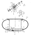
- Figure 1 is a cross-sectional view of a vehicle wheel incorporating the present invention.
- Figure 2 is an enlarged portion of the vehicle wheel along line 2-2 as shown in Figure 1 .
- Figure 3 is an exploded view of an inventive sensor mount.
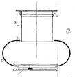
- Figure 4 is an assembly view of the inventive wheel.
- Figure 1 shows a vehicle wheel 20 incorporating a tire 22.
- tire 22 has beads 26 and 42, which seal on a rim 21.
- the rim 21 includes an end disc 24 that receives bead 26 on a surface 28.
- An inner face 34 of disc 24 is positioned inwardly of the bead 26.
- a weld joint 27 secures the bead 26 to the surface 28.
- an air valve 29 allows air to be inserted through the disc 24 and into an internal cavity 33 within the tire 22.
- a sensor 30 is preferably mounted in the disc 24.
- a hole 32 communicates with the cavity 33, and supplies air pressure information to the sensor 30.
- Sensor 30 may be as known in the art, and is capable of reading the air pressure within the cavity 33, and storing information with regard to the pressure.
- the sensor 30 is preferably provided with a speed sensor for sensing the speed of movement or rotation of the wheel 20.
- Sensor 30 is also preferably provided with the ability to transmit signals to the control on a vehicle. This transmission may be battery powered, or may be powered through an LF coupling, as is known.
- the disc 24 mates with an internal rim part 38 to form rim 21. Both disc 24 and internal rim part 38 are formed from a suitable non-metallic material, such as high strength plastic.
- a surface 40 receives the bead 42 from the tire 22. Again, a weld joint 43 secures the bead 42 to the surface 40.
- the senor 30 is mounted within the disc 24.
- the hole 32 extends through the disc 24 to communicate air pressure to the sensor 30.
- FIG. 3 is an exploded view of the sensor 30.
- a housing 50 receives the sensor body 52, and an antenna 53, shown schematically.
- the sensor body 52 and its communication with its antenna 53 may be as known in the art.
- Housing 50 is preferably molded into a portion of the disc 24.
- the sensor body 52 receives a plate 54, a seal 56, a nut 58, and a cap 60.
- the structure and operation of the sensor may again be as known in the art. Its location and incorporation into the rim, however, is inventive.
- Figure 4 shows another feature and in particular the assembly steps of the inventive vehicle wheel 20.
- the disc 24 initially receives the bead 26 from the tire 22.
- the internal rim part 38 is then moved into the inner periphery of the disc 24.
- the two rim parts may then be welded together, and the two beads 26 and 42 are welded to their respective surfaces, as is shown in Figure 1 .
- laser welding may be used.
Landscapes
- Engineering & Computer Science (AREA)
- Mechanical Engineering (AREA)
- Chemical & Material Sciences (AREA)
- Materials Engineering (AREA)
- Measuring Fluid Pressure (AREA)
Abstract
Description
- This invention relates to a unique vehicle wheel, wherein a sensor is attached within the wheel and the rim is formed of a non-metallic material.
- Vehicle wheels typically include an outer rubber tire secured to a rim. The rims have historically been formed of metal. Normally, the tire may be removed from the metal rim for replacement, as necessary.
- Recently, plastics and composite materials have advanced to the point where they are sufficiently strong such that they could be utilized as wheel rims. However, there has not been sufficient motivation to drive this change. In order to reduce weight,
US 5,282,673 proposes a compound resin wheel. - Also, recently, tire pressure sensors have become required in the industry. Tire pressure sensors have typically been mounted in the prior art wheel at various locations. One common location incorporates the sensor adjacent to the air valve. Also, an antenna for transmitting signals from the sensor to a controller on the vehicle has been incorporated into the air valve. This has required the air valve to be formed of materials other than the standard rubber that has been previously utilized. It would be desirable to allow the use of standard air valves.
- Another concern with the prior art tire pressure sensors is that the metal rims have made the transmission of signals from the sensor difficult. The signals have sometimes been difficult to send, due to the shielding of the signal that can occur from the metal rim. It would be desirable in many applications to send the sensor information via a wireless RF, LF or other such radio signal.
-
EP 0 503 296 proposes that in a device for monitoring the air pressure inside a pneumatic tyre, supported by the rim of a vehicle wheel, using a pressure or measurement value signal generator which can be acted on by the tyre pressure and in whose circumferential area a measurement value sensor or similar signal sensor which is fixed to the vehicle in a stationary fashion is arranged, the pressure signal generator is arranged near to the axis of the wheel and connected to the inside of the tyre by means of at least one air passage running on or in the rim. In addition, the pressure signal generator is to be connected to the inside of the tyre by means of a line which leads to it directly from the rim base, and said line is to be made, if appropriate, of flexible material or the air passage is to be at least one channel formed into the rim. However, this solution involves several elements outside of the tire to be under pressure and an air passage on or in the rim, which is involves an increased risk of leakage as well as more complex manufacturing and maintenance. It is therefore the objective of the present invention to provide a wheel that can be constructed in a more simple way and with a reduced risk of leakage and that still allows to transmit a measured value for a tire pressure. This problem is solved by the measures taken in accordance with the independent claim. - In a disclosed embodiment of this invention, a vehicle wheel is manufactured utilizing a non-metallic rim. While plastic is preferred, other non-metallic materials, such as composites, may be utilized. A tire could be permanently attached to the plastic rim such that the rim will not allow replacement of the tire. A sensor and antenna are incorporated into the tire and rim, and record information about the operation of the vehicle wheel. Most preferably, the sensor is incorporated into a portion of the rim. The rim preferably is molded from two pieces of plastic, with an end disc and an internal rim part, fitting within the end disc. The sensor is preferably snapped into a mounting bracket molded to one of the two pieces that form the rim.
- The disc initially receives one bead of the tire, and the internal rim part is then inserted into the disc. At that point, the other bead on the tire seats on the internal rim part. Both beads are then welded to the rim parts.
- Preferably, a port is used to allow air pressure to reach the sensor from within a sealed volume in the tire. In this manner, the sensor receives pressure information, and can transmit and store this information. Moreover, the sensor is preferably provided with a speed sensor (which could be an accelerometer) and an antenna. The sensor is thus able to store not only information with regard to the tire pressure, but also information with regard to the speed of the tire, the hours of operation, etc. The sensor may be provided with a memory such that it stores an effective life history of the wheel. The sensor is also able to transmit signals to a control on the vehicle through a wireless connection. The sensor may be provided with its own battery, or may receive a charging signal as is known in the art to charge itself for transmission of the wireless signal.
- These and other features of the present invention can be best understood from the following specification and drawings, the following of which is a brief description.
-
Figure 1 is a cross-sectional view of a vehicle wheel incorporating the present invention. -
Figure 2 is an enlarged portion of the vehicle wheel along line 2-2 as shown inFigure 1 . -
Figure 3 is an exploded view of an inventive sensor mount. -
Figure 4 is an assembly view of the inventive wheel. -
Figure 1 shows avehicle wheel 20 incorporating atire 22. As is known,tire 22 hasbeads end disc 24 that receivesbead 26 on asurface 28. Aninner face 34 ofdisc 24 is positioned inwardly of thebead 26. A weld joint 27 secures thebead 26 to thesurface 28. As shown schematically, anair valve 29 allows air to be inserted through thedisc 24 and into aninternal cavity 33 within thetire 22. - A
sensor 30 is preferably mounted in thedisc 24. Ahole 32 communicates with thecavity 33, and supplies air pressure information to thesensor 30.Sensor 30 may be as known in the art, and is capable of reading the air pressure within thecavity 33, and storing information with regard to the pressure. Further, thesensor 30 is preferably provided with a speed sensor for sensing the speed of movement or rotation of thewheel 20.Sensor 30 is also preferably provided with the ability to transmit signals to the control on a vehicle. This transmission may be battery powered, or may be powered through an LF coupling, as is known. Thedisc 24 mates with aninternal rim part 38 to form rim 21. Bothdisc 24 andinternal rim part 38 are formed from a suitable non-metallic material, such as high strength plastic. As shown, asurface 40 receives thebead 42 from thetire 22. Again, aweld joint 43 secures thebead 42 to thesurface 40. - As shown in
Figure 2 , as can be appreciated, thesensor 30 is mounted within thedisc 24. Thehole 32 extends through thedisc 24 to communicate air pressure to thesensor 30. -
Figure 3 is an exploded view of thesensor 30. As shown, ahousing 50 receives the sensor body 52, and an antenna 53, shown schematically. The sensor body 52 and its communication with its antenna 53 may be as known in the art.Housing 50 is preferably molded into a portion of thedisc 24. The sensor body 52 receives a plate 54, a seal 56, a nut 58, and a cap 60. The structure and operation of the sensor may again be as known in the art. Its location and incorporation into the rim, however, is inventive. -
Figure 4 shows another feature and in particular the assembly steps of theinventive vehicle wheel 20. As shown, thedisc 24 initially receives thebead 26 from thetire 22. Theinternal rim part 38 is then moved into the inner periphery of thedisc 24. The two rim parts may then be welded together, and the twobeads Figure 1 . Preferably, laser welding may be used. - Although a preferred embodiment of this invention has been disclosed, a worker of ordinary skill in this art would recognize that certain modifications would come within the scope of this invention. For that reason, the following claims should be studied to determine the true scope and content of this invention.
Claims (12)
- A vehicle wheel (20) comprising:a rim (21) formed from a non-metallic material;a tire (22) having a pair of beads (26, 42) secured to said rim (21), and defining an enclosed chamber between said beads (26, 42) and said rim (21); anda sensor (30) for sensing a pressure in said enclosed chamber, said sensor (30) communicating with air in said enclosed chamber, and said sensor (30) being capable of transmitting a pressure signal outwardly of said vehicle wheel (20); andwherein said sensor (30) is mounted within a housing (50) molded to a portion of said rim (21).
- The vehicle wheel (20) as set forth in claim 1, wherein said rim (21) is formed of two pieces, with a disc (24) receiving one bead (26, 42) of said tire and a second internal rim part secured to said disc (24) and secured to a second bead (26, 42) of said tire (22).
- The vehicle wheel (20) as set forth in claim 2, wherein said sensor (30) is mounted within said disc (24).
- The vehicle wheel (20) as set forth in claim 3, wherein said sensor (30) receives an antenna (53).
- The vehicle wheel (20) as set forth in claim 4, wherein said sensor (30) is capable of transmitting pressure information as an LF signal.
- The vehicle wheel (20) as set forth in claim 4, wherein said sensor (30) is capable of transmitting pressure information as an RF signal.
- The vehicle wheel (20) as set forth in claim 2, wherein said sensor (30) includes a speed sensor, said sensor (30) recording information with regard to time of operation of said vehicle wheel (20), and speed of operation of said vehicle wheel (20).
- The vehicle wheel (20) as set forth in claim 7, wherein said sensor (30) stores identification about which wheel (20) is in service and the location on the vehicle.
- The vehicle wheel (20) as set forth in claim 2, wherein an air pressure hole (32) extends through said (24) disc to communicate air from said enclosed chamber to said sensor (30).
- The vehicle wheel (20) as set forth in claim 1, wherein said tire (22) is not removable from said rim (21).
- The vehicle wheel (20) as set forth in claim 1, wherein said rim (21) is formed of a plastic.
- The vehicle wheel (20) as set forth in claim 1, wherein said sensor (30) stores a life history of the vehicle wheel.
Applications Claiming Priority (4)
| Application Number | Priority Date | Filing Date | Title |
|---|---|---|---|
| US47248203P | 2003-05-21 | 2003-05-21 | |
| US472482P | 2003-05-21 | ||
| US47456403P | 2003-05-30 | 2003-05-30 | |
| US474564P | 2003-05-30 |
Publications (3)
| Publication Number | Publication Date |
|---|---|
| EP1479533A2 EP1479533A2 (en) | 2004-11-24 |
| EP1479533A3 EP1479533A3 (en) | 2008-11-19 |
| EP1479533B1 true EP1479533B1 (en) | 2012-05-09 |
Family
ID=33101525
Family Applications (1)
| Application Number | Title | Priority Date | Filing Date |
|---|---|---|---|
| EP04011747A Expired - Lifetime EP1479533B1 (en) | 2003-05-21 | 2004-05-18 | Wheel with plastic rim and integral sensor |
Country Status (3)
| Country | Link |
|---|---|
| US (1) | US20040261512A1 (en) |
| EP (1) | EP1479533B1 (en) |
| AT (1) | ATE556867T1 (en) |
Cited By (4)
| Publication number | Priority date | Publication date | Assignee | Title |
|---|---|---|---|---|
| US8186766B2 (en) | 2002-11-08 | 2012-05-29 | Campagnolo, S.p.l. | Bicycle spoked wheel and method for manufacturing the same |
| US8668278B2 (en) | 2007-11-26 | 2014-03-11 | Campagnolo S.R.L. | Rim for a bicycle wheel and bicycle wheel comprising such a rim |
| US8777328B2 (en) | 2007-11-26 | 2014-07-15 | Campagnolo S.R.L. | Rim for a bicycle wheel and bicycle wheel comprising such a rim |
| US9079454B2 (en) | 2008-03-14 | 2015-07-14 | Campagnolo S.R.L. | Rim made from composite material for a tubeless bicycle bicycle wheel and tubeless bicycle wheel comprising such a rim |
Families Citing this family (4)
| Publication number | Priority date | Publication date | Assignee | Title |
|---|---|---|---|---|
| ATE400453T1 (en) | 2003-08-11 | 2008-07-15 | Campagnolo Srl | COMPOSITE BICYCLE RIM AND METHOD FOR PRODUCING SAME |
| FI120936B (en) * | 2005-06-27 | 2010-05-14 | Secure Oy W | The alarm system |
| DE102010037524B3 (en) * | 2010-09-14 | 2012-03-01 | Saint-Gobain Sekurit Deutschland Gmbh & Co. Kg | vehicle rim |
| FR3097329B1 (en) * | 2019-06-13 | 2021-07-02 | Safran Landing Systems | Aircraft wheel and brake assembly |
Family Cites Families (18)
| Publication number | Priority date | Publication date | Assignee | Title |
|---|---|---|---|---|
| US3846201A (en) * | 1972-11-02 | 1974-11-05 | Brad Ragan Inc | Assembly and method for bonding tread material to a tire body |
| US4163208A (en) * | 1975-12-18 | 1979-07-31 | Merz Ernest J | Automatic wireless tire pressure monitoring system |
| US4350196A (en) * | 1976-09-13 | 1982-09-21 | The Goodyear Tire & Rubber Company | Non-pneumatic structurally resilient integrated wheel-tire |
| US4235185A (en) * | 1979-07-18 | 1980-11-25 | General Motors Corporation | Low tire pressure sensor and air switch therefor |
| US6735506B2 (en) * | 1992-05-05 | 2004-05-11 | Automotive Technologies International, Inc. | Telematics system |
| DE4108338A1 (en) * | 1991-03-14 | 1992-09-17 | Alligator Ventilfab Gmbh | DEVICE FOR MONITORING THE AIR PRESSURE OF A VEHICLE WHEEL |
| JP3134361B2 (en) * | 1991-07-16 | 2001-02-13 | 株式会社ブリヂストン | Composite resin wheel |
| US5218862A (en) * | 1992-01-21 | 1993-06-15 | General Motors Corporation | Tire pressure monitor |
| US6055925A (en) * | 1994-09-12 | 2000-05-02 | Horton; William E. | Air gauge wheel |
| CA2168940C (en) * | 1995-02-08 | 2007-05-01 | Kenji Furuichi | Tire pressure detector |
| US5844131A (en) * | 1995-06-26 | 1998-12-01 | Alligator Ventilfabrik Gmbh | Tire pressure sensor apparatus for a pneumatic tire of a vehicle |
| TW317541B (en) * | 1995-10-13 | 1997-10-11 | Chrysler Corp | |
| JP3317905B2 (en) * | 1998-09-07 | 2002-08-26 | 太平洋工業株式会社 | Casing structure of transmitter for tire pressure warning device |
| TW520332B (en) * | 2000-09-02 | 2003-02-11 | Lite On Automotive Corp | Status sensor of inflated automobile tire |
| US6631637B2 (en) * | 2001-04-12 | 2003-10-14 | Siemens Vdo Automotive Corporation | Sensor mounting assembly for a vehicle tire |
| FR2829063B1 (en) * | 2001-09-06 | 2003-10-31 | Siemens Vdo Automotive Sas | DEVICE FOR MOUNTING A SENSOR ON A MOTOR VEHICLE WHEEL RIM AND ASSOCIATED MOUNTING METHOD |
| US6805000B1 (en) * | 2002-02-11 | 2004-10-19 | Smartire Systems, Inc. | Apparatus and method for mounting a tire condition sensor capsule to a wheel rim |
| US20040021365A1 (en) * | 2002-05-13 | 2004-02-05 | Alan Georgeff | Two-piece vehicle wheel |
-
2004
- 2004-05-17 US US10/847,213 patent/US20040261512A1/en not_active Abandoned
- 2004-05-18 AT AT04011747T patent/ATE556867T1/en active
- 2004-05-18 EP EP04011747A patent/EP1479533B1/en not_active Expired - Lifetime
Cited By (4)
| Publication number | Priority date | Publication date | Assignee | Title |
|---|---|---|---|---|
| US8186766B2 (en) | 2002-11-08 | 2012-05-29 | Campagnolo, S.p.l. | Bicycle spoked wheel and method for manufacturing the same |
| US8668278B2 (en) | 2007-11-26 | 2014-03-11 | Campagnolo S.R.L. | Rim for a bicycle wheel and bicycle wheel comprising such a rim |
| US8777328B2 (en) | 2007-11-26 | 2014-07-15 | Campagnolo S.R.L. | Rim for a bicycle wheel and bicycle wheel comprising such a rim |
| US9079454B2 (en) | 2008-03-14 | 2015-07-14 | Campagnolo S.R.L. | Rim made from composite material for a tubeless bicycle bicycle wheel and tubeless bicycle wheel comprising such a rim |
Also Published As
| Publication number | Publication date |
|---|---|
| EP1479533A3 (en) | 2008-11-19 |
| EP1479533A2 (en) | 2004-11-24 |
| US20040261512A1 (en) | 2004-12-30 |
| ATE556867T1 (en) | 2012-05-15 |
Similar Documents
| Publication | Publication Date | Title |
|---|---|---|
| US5505080A (en) | Tire pressure management system | |
| EP1377468B1 (en) | Sensor mounting assembly for a vehicle tire | |
| EP3670213B1 (en) | Control system for an air maintenance tire system | |
| EP1479533B1 (en) | Wheel with plastic rim and integral sensor | |
| CA2482242A1 (en) | Method of integrating tire identification into a vehicle information system | |
| EP2021194B1 (en) | Tire risk judging device of wheel assembly for vehicle | |
| US8631695B2 (en) | Extended valve stem Cap | |
| JP2003267006A (en) | Tire pressure detector of motor vehicle tire | |
| US6829926B2 (en) | System for checking the air pressure in the tires of a motor vehicle | |
| US20030201881A1 (en) | Tire inflation monitoring system | |
| US7392695B2 (en) | Wheel assembly, wheel and wheel condition determining apparatus | |
| EP3981613B1 (en) | System for detection of non-pneumatic tire loading | |
| EP1181162B1 (en) | System for checking the air pressure in the tyres of a motor vehicle | |
| JP2009537378A (en) | Run-flat safety band including radio equipment | |
| KR101658977B1 (en) | Transmitter apparatus for transmitting tire information, and tire information monitoring system | |
| EP4070967B1 (en) | Assembly for an inner tyre tube | |
| US7784337B2 (en) | Sensor of tire pressure monitoring system | |
| EP3055145B1 (en) | System for indirectly monitoring the inflation pressure of pneumatic-tyred vehicle wheels and vehicle wheel therefore | |
| US11198335B2 (en) | Integrated-sensor valve apparatus | |
| WO2001056814A1 (en) | Improved monitoring system | |
| CN216331246U (en) | Spherical tire pressure sensor | |
| US20260044693A1 (en) | Method for reading information contained in an rfid chip embedded in a vehicle tire | |
| JP2006044562A (en) | Vehicle wheel | |
| WO2025099664A1 (en) | Pneumatic tyre equipped with an electronic device and corresponding production method | |
| CN100473551C (en) | External tire pressure sensing system |
Legal Events
| Date | Code | Title | Description |
|---|---|---|---|
| PUAI | Public reference made under article 153(3) epc to a published international application that has entered the european phase |
Free format text: ORIGINAL CODE: 0009012 |
|
| AK | Designated contracting states |
Kind code of ref document: A2 Designated state(s): AT BE BG CH CY CZ DE DK EE ES FI FR GB GR HU IE IT LI LU MC NL PL PT RO SE SI SK TR |
|
| AX | Request for extension of the european patent |
Extension state: AL HR LT LV MK |
|
| PUAL | Search report despatched |
Free format text: ORIGINAL CODE: 0009013 |
|
| AK | Designated contracting states |
Kind code of ref document: A3 Designated state(s): AT BE BG CH CY CZ DE DK EE ES FI FR GB GR HU IE IT LI LU MC NL PL PT RO SE SI SK TR |
|
| AX | Request for extension of the european patent |
Extension state: AL HR LT LV MK |
|
| RAP1 | Party data changed (applicant data changed or rights of an application transferred) |
Owner name: CONTINENTAL AUTOMOTIVE SYSTEMS US, INC. |
|
| 17P | Request for examination filed |
Effective date: 20090519 |
|
| AKX | Designation fees paid |
Designated state(s): AT BE BG CH CY CZ DE DK EE ES FI FR GB GR HU IE IT LI LU MC NL PL PT RO SE SI SK TR |
|
| 17Q | First examination report despatched |
Effective date: 20091118 |
|
| GRAP | Despatch of communication of intention to grant a patent |
Free format text: ORIGINAL CODE: EPIDOSNIGR1 |
|
| GRAS | Grant fee paid |
Free format text: ORIGINAL CODE: EPIDOSNIGR3 |
|
| GRAA | (expected) grant |
Free format text: ORIGINAL CODE: 0009210 |
|
| AK | Designated contracting states |
Kind code of ref document: B1 Designated state(s): AT BE BG CH CY CZ DE DK EE ES FI FR GB GR HU IE IT LI LU MC NL PL PT RO SE SI SK TR |
|
| REG | Reference to a national code |
Ref country code: GB Ref legal event code: FG4D |
|
| REG | Reference to a national code |
Ref country code: CH Ref legal event code: EP Ref country code: AT Ref legal event code: REF Ref document number: 556867 Country of ref document: AT Kind code of ref document: T Effective date: 20120515 |
|
| REG | Reference to a national code |
Ref country code: IE Ref legal event code: FG4D |
|
| REG | Reference to a national code |
Ref country code: DE Ref legal event code: R096 Ref document number: 602004037706 Country of ref document: DE Effective date: 20120712 |
|
| REG | Reference to a national code |
Ref country code: NL Ref legal event code: VDEP Effective date: 20120509 |
|
| PG25 | Lapsed in a contracting state [announced via postgrant information from national office to epo] |
Ref country code: PL Free format text: LAPSE BECAUSE OF FAILURE TO SUBMIT A TRANSLATION OF THE DESCRIPTION OR TO PAY THE FEE WITHIN THE PRESCRIBED TIME-LIMIT Effective date: 20120509 Ref country code: FI Free format text: LAPSE BECAUSE OF FAILURE TO SUBMIT A TRANSLATION OF THE DESCRIPTION OR TO PAY THE FEE WITHIN THE PRESCRIBED TIME-LIMIT Effective date: 20120509 Ref country code: CY Free format text: LAPSE BECAUSE OF FAILURE TO SUBMIT A TRANSLATION OF THE DESCRIPTION OR TO PAY THE FEE WITHIN THE PRESCRIBED TIME-LIMIT Effective date: 20120509 Ref country code: SE Free format text: LAPSE BECAUSE OF FAILURE TO SUBMIT A TRANSLATION OF THE DESCRIPTION OR TO PAY THE FEE WITHIN THE PRESCRIBED TIME-LIMIT Effective date: 20120509 |
|
| REG | Reference to a national code |
Ref country code: AT Ref legal event code: MK05 Ref document number: 556867 Country of ref document: AT Kind code of ref document: T Effective date: 20120509 |
|
| PG25 | Lapsed in a contracting state [announced via postgrant information from national office to epo] |
Ref country code: SI Free format text: LAPSE BECAUSE OF FAILURE TO SUBMIT A TRANSLATION OF THE DESCRIPTION OR TO PAY THE FEE WITHIN THE PRESCRIBED TIME-LIMIT Effective date: 20120509 Ref country code: PT Free format text: LAPSE BECAUSE OF FAILURE TO SUBMIT A TRANSLATION OF THE DESCRIPTION OR TO PAY THE FEE WITHIN THE PRESCRIBED TIME-LIMIT Effective date: 20120910 Ref country code: GR Free format text: LAPSE BECAUSE OF FAILURE TO SUBMIT A TRANSLATION OF THE DESCRIPTION OR TO PAY THE FEE WITHIN THE PRESCRIBED TIME-LIMIT Effective date: 20120810 |
|
| PG25 | Lapsed in a contracting state [announced via postgrant information from national office to epo] |
Ref country code: BE Free format text: LAPSE BECAUSE OF FAILURE TO SUBMIT A TRANSLATION OF THE DESCRIPTION OR TO PAY THE FEE WITHIN THE PRESCRIBED TIME-LIMIT Effective date: 20120509 Ref country code: MC Free format text: LAPSE BECAUSE OF NON-PAYMENT OF DUE FEES Effective date: 20120531 |
|
| REG | Reference to a national code |
Ref country code: CH Ref legal event code: PL |
|
| PG25 | Lapsed in a contracting state [announced via postgrant information from national office to epo] |
Ref country code: CH Free format text: LAPSE BECAUSE OF NON-PAYMENT OF DUE FEES Effective date: 20120531 Ref country code: CZ Free format text: LAPSE BECAUSE OF FAILURE TO SUBMIT A TRANSLATION OF THE DESCRIPTION OR TO PAY THE FEE WITHIN THE PRESCRIBED TIME-LIMIT Effective date: 20120509 Ref country code: SK Free format text: LAPSE BECAUSE OF FAILURE TO SUBMIT A TRANSLATION OF THE DESCRIPTION OR TO PAY THE FEE WITHIN THE PRESCRIBED TIME-LIMIT Effective date: 20120509 Ref country code: AT Free format text: LAPSE BECAUSE OF FAILURE TO SUBMIT A TRANSLATION OF THE DESCRIPTION OR TO PAY THE FEE WITHIN THE PRESCRIBED TIME-LIMIT Effective date: 20120509 Ref country code: NL Free format text: LAPSE BECAUSE OF FAILURE TO SUBMIT A TRANSLATION OF THE DESCRIPTION OR TO PAY THE FEE WITHIN THE PRESCRIBED TIME-LIMIT Effective date: 20120509 Ref country code: DK Free format text: LAPSE BECAUSE OF FAILURE TO SUBMIT A TRANSLATION OF THE DESCRIPTION OR TO PAY THE FEE WITHIN THE PRESCRIBED TIME-LIMIT Effective date: 20120509 Ref country code: LI Free format text: LAPSE BECAUSE OF NON-PAYMENT OF DUE FEES Effective date: 20120531 Ref country code: EE Free format text: LAPSE BECAUSE OF FAILURE TO SUBMIT A TRANSLATION OF THE DESCRIPTION OR TO PAY THE FEE WITHIN THE PRESCRIBED TIME-LIMIT Effective date: 20120509 Ref country code: RO Free format text: LAPSE BECAUSE OF FAILURE TO SUBMIT A TRANSLATION OF THE DESCRIPTION OR TO PAY THE FEE WITHIN THE PRESCRIBED TIME-LIMIT Effective date: 20120509 |
|
| REG | Reference to a national code |
Ref country code: IE Ref legal event code: MM4A |
|
| PG25 | Lapsed in a contracting state [announced via postgrant information from national office to epo] |
Ref country code: IT Free format text: LAPSE BECAUSE OF FAILURE TO SUBMIT A TRANSLATION OF THE DESCRIPTION OR TO PAY THE FEE WITHIN THE PRESCRIBED TIME-LIMIT Effective date: 20120509 |
|
| PLBE | No opposition filed within time limit |
Free format text: ORIGINAL CODE: 0009261 |
|
| STAA | Information on the status of an ep patent application or granted ep patent |
Free format text: STATUS: NO OPPOSITION FILED WITHIN TIME LIMIT |
|
| 26N | No opposition filed |
Effective date: 20130212 |
|
| GBPC | Gb: european patent ceased through non-payment of renewal fee |
Effective date: 20120809 |
|
| PG25 | Lapsed in a contracting state [announced via postgrant information from national office to epo] |
Ref country code: ES Free format text: LAPSE BECAUSE OF FAILURE TO SUBMIT A TRANSLATION OF THE DESCRIPTION OR TO PAY THE FEE WITHIN THE PRESCRIBED TIME-LIMIT Effective date: 20120820 Ref country code: IE Free format text: LAPSE BECAUSE OF NON-PAYMENT OF DUE FEES Effective date: 20120518 |
|
| REG | Reference to a national code |
Ref country code: DE Ref legal event code: R097 Ref document number: 602004037706 Country of ref document: DE Effective date: 20130212 |
|
| PG25 | Lapsed in a contracting state [announced via postgrant information from national office to epo] |
Ref country code: GB Free format text: LAPSE BECAUSE OF NON-PAYMENT OF DUE FEES Effective date: 20120809 Ref country code: BG Free format text: LAPSE BECAUSE OF FAILURE TO SUBMIT A TRANSLATION OF THE DESCRIPTION OR TO PAY THE FEE WITHIN THE PRESCRIBED TIME-LIMIT Effective date: 20120809 |
|
| REG | Reference to a national code |
Ref country code: DE Ref legal event code: R082 Ref document number: 602004037706 Country of ref document: DE Representative=s name: FISCHER, MICHAEL, DR., DE |
|
| REG | Reference to a national code |
Ref country code: DE Ref legal event code: R081 Ref document number: 602004037706 Country of ref document: DE Owner name: CONTINENTAL AUTOMOTIVE SYSTEMS, INC. ( N. D. G, US Free format text: FORMER OWNER: CONTINENTAL AUTOMOTIVE SYSTEMS US, INC., AUBURN HILLS, US Effective date: 20140317 Ref country code: DE Ref legal event code: R082 Ref document number: 602004037706 Country of ref document: DE Representative=s name: FISCHER, MICHAEL, DR., DE Effective date: 20140317 Ref country code: DE Ref legal event code: R081 Ref document number: 602004037706 Country of ref document: DE Owner name: CONTINENTAL AUTOMOTIVE SYSTEMS, INC. ( N. D. G, US Free format text: FORMER OWNER: SIEMENS VDO AUTOMOTIVE CORP., AUBURN HILLS, US Effective date: 20120518 Ref country code: DE Ref legal event code: R081 Ref document number: 602004037706 Country of ref document: DE Owner name: CONTINENTAL AUTOMOTIVE SYSTEMS, INC. ( N. D. G, US Free format text: FORMER OWNER: CONTINENTAL AUTOMOTIVE SYSTEMS US, INC., AUBURN HILLS, MICH., US Effective date: 20140317 Ref country code: DE Ref legal event code: R081 Ref document number: 602004037706 Country of ref document: DE Owner name: CONTINENTAL AUTOMOTIVE SYSTEMS, INC. ( N. D. G, US Free format text: FORMER OWNER: SIEMENS VDO AUTOMOTIVE CORP., AUBURN HILLS, MICH., US Effective date: 20120518 |
|
| PG25 | Lapsed in a contracting state [announced via postgrant information from national office to epo] |
Ref country code: TR Free format text: LAPSE BECAUSE OF FAILURE TO SUBMIT A TRANSLATION OF THE DESCRIPTION OR TO PAY THE FEE WITHIN THE PRESCRIBED TIME-LIMIT Effective date: 20120509 |
|
| PG25 | Lapsed in a contracting state [announced via postgrant information from national office to epo] |
Ref country code: LU Free format text: LAPSE BECAUSE OF NON-PAYMENT OF DUE FEES Effective date: 20120518 |
|
| PG25 | Lapsed in a contracting state [announced via postgrant information from national office to epo] |
Ref country code: HU Free format text: LAPSE BECAUSE OF FAILURE TO SUBMIT A TRANSLATION OF THE DESCRIPTION OR TO PAY THE FEE WITHIN THE PRESCRIBED TIME-LIMIT Effective date: 20040518 |
|
| REG | Reference to a national code |
Ref country code: FR Ref legal event code: PLFP Year of fee payment: 13 |
|
| REG | Reference to a national code |
Ref country code: FR Ref legal event code: PLFP Year of fee payment: 14 |
|
| REG | Reference to a national code |
Ref country code: FR Ref legal event code: PLFP Year of fee payment: 15 |
|
| PGFP | Annual fee paid to national office [announced via postgrant information from national office to epo] |
Ref country code: DE Payment date: 20210531 Year of fee payment: 18 Ref country code: FR Payment date: 20210520 Year of fee payment: 18 |
|
| REG | Reference to a national code |
Ref country code: DE Ref legal event code: R119 Ref document number: 602004037706 Country of ref document: DE |
|
| PG25 | Lapsed in a contracting state [announced via postgrant information from national office to epo] |
Ref country code: FR Free format text: LAPSE BECAUSE OF NON-PAYMENT OF DUE FEES Effective date: 20220531 |
|
| PG25 | Lapsed in a contracting state [announced via postgrant information from national office to epo] |
Ref country code: DE Free format text: LAPSE BECAUSE OF NON-PAYMENT OF DUE FEES Effective date: 20221201 |