EP1478409B1 - Hydrogen peroxide vapor system with replaceable desiccant cartridge - Google Patents
Hydrogen peroxide vapor system with replaceable desiccant cartridge Download PDFInfo
- Publication number
- EP1478409B1 EP1478409B1 EP03709423A EP03709423A EP1478409B1 EP 1478409 B1 EP1478409 B1 EP 1478409B1 EP 03709423 A EP03709423 A EP 03709423A EP 03709423 A EP03709423 A EP 03709423A EP 1478409 B1 EP1478409 B1 EP 1478409B1
- Authority
- EP
- European Patent Office
- Prior art keywords
- desiccant
- cartridge
- vapor
- set forth
- dryer
- Prior art date
- Legal status (The legal status is an assumption and is not a legal conclusion. Google has not performed a legal analysis and makes no representation as to the accuracy of the status listed.)
- Expired - Lifetime
Links
Images


Classifications
-
- A—HUMAN NECESSITIES
- A61—MEDICAL OR VETERINARY SCIENCE; HYGIENE
- A61L—METHODS OR APPARATUS FOR STERILISING MATERIALS OR OBJECTS IN GENERAL; DISINFECTION, STERILISATION OR DEODORISATION OF AIR; CHEMICAL ASPECTS OF BANDAGES, DRESSINGS, ABSORBENT PADS OR SURGICAL ARTICLES; MATERIALS FOR BANDAGES, DRESSINGS, ABSORBENT PADS OR SURGICAL ARTICLES
- A61L2/00—Methods or apparatus for disinfecting or sterilising materials or objects other than foodstuffs or contact lenses; Accessories therefor
- A61L2/16—Methods or apparatus for disinfecting or sterilising materials or objects other than foodstuffs or contact lenses; Accessories therefor using chemical substances
- A61L2/20—Gaseous substances, e.g. vapours
- A61L2/208—Hydrogen peroxide
-
- A—HUMAN NECESSITIES
- A61—MEDICAL OR VETERINARY SCIENCE; HYGIENE
- A61L—METHODS OR APPARATUS FOR STERILISING MATERIALS OR OBJECTS IN GENERAL; DISINFECTION, STERILISATION OR DEODORISATION OF AIR; CHEMICAL ASPECTS OF BANDAGES, DRESSINGS, ABSORBENT PADS OR SURGICAL ARTICLES; MATERIALS FOR BANDAGES, DRESSINGS, ABSORBENT PADS OR SURGICAL ARTICLES
- A61L2/00—Methods or apparatus for disinfecting or sterilising materials or objects other than foodstuffs or contact lenses; Accessories therefor
- A61L2/16—Methods or apparatus for disinfecting or sterilising materials or objects other than foodstuffs or contact lenses; Accessories therefor using chemical substances
- A61L2/20—Gaseous substances, e.g. vapours
-
- A—HUMAN NECESSITIES
- A61—MEDICAL OR VETERINARY SCIENCE; HYGIENE
- A61L—METHODS OR APPARATUS FOR STERILISING MATERIALS OR OBJECTS IN GENERAL; DISINFECTION, STERILISATION OR DEODORISATION OF AIR; CHEMICAL ASPECTS OF BANDAGES, DRESSINGS, ABSORBENT PADS OR SURGICAL ARTICLES; MATERIALS FOR BANDAGES, DRESSINGS, ABSORBENT PADS OR SURGICAL ARTICLES
- A61L2/00—Methods or apparatus for disinfecting or sterilising materials or objects other than foodstuffs or contact lenses; Accessories therefor
- A61L2/26—Accessories or devices or components used for biocidal treatment
-
- B—PERFORMING OPERATIONS; TRANSPORTING
- B01—PHYSICAL OR CHEMICAL PROCESSES OR APPARATUS IN GENERAL
- B01D—SEPARATION
- B01D53/00—Separation of gases or vapours; Recovering vapours of volatile solvents from gases; Chemical or biological purification of waste gases, e.g. engine exhaust gases, smoke, fumes, flue gases, aerosols
- B01D53/02—Separation of gases or vapours; Recovering vapours of volatile solvents from gases; Chemical or biological purification of waste gases, e.g. engine exhaust gases, smoke, fumes, flue gases, aerosols by adsorption, e.g. preparative gas chromatography
- B01D53/04—Separation of gases or vapours; Recovering vapours of volatile solvents from gases; Chemical or biological purification of waste gases, e.g. engine exhaust gases, smoke, fumes, flue gases, aerosols by adsorption, e.g. preparative gas chromatography with stationary adsorbents
- B01D53/0407—Constructional details of adsorbing systems
- B01D53/0415—Beds in cartridges
-
- B—PERFORMING OPERATIONS; TRANSPORTING
- B01—PHYSICAL OR CHEMICAL PROCESSES OR APPARATUS IN GENERAL
- B01D—SEPARATION
- B01D53/00—Separation of gases or vapours; Recovering vapours of volatile solvents from gases; Chemical or biological purification of waste gases, e.g. engine exhaust gases, smoke, fumes, flue gases, aerosols
- B01D53/26—Drying gases or vapours
- B01D53/261—Drying gases or vapours by adsorption
-
- A—HUMAN NECESSITIES
- A61—MEDICAL OR VETERINARY SCIENCE; HYGIENE
- A61L—METHODS OR APPARATUS FOR STERILISING MATERIALS OR OBJECTS IN GENERAL; DISINFECTION, STERILISATION OR DEODORISATION OF AIR; CHEMICAL ASPECTS OF BANDAGES, DRESSINGS, ABSORBENT PADS OR SURGICAL ARTICLES; MATERIALS FOR BANDAGES, DRESSINGS, ABSORBENT PADS OR SURGICAL ARTICLES
- A61L2202/00—Aspects relating to methods or apparatus for disinfecting or sterilising materials or objects
- A61L2202/10—Apparatus features
- A61L2202/11—Apparatus for generating biocidal substances, e.g. vaporisers, UV lamps
-
- A—HUMAN NECESSITIES
- A61—MEDICAL OR VETERINARY SCIENCE; HYGIENE
- A61L—METHODS OR APPARATUS FOR STERILISING MATERIALS OR OBJECTS IN GENERAL; DISINFECTION, STERILISATION OR DEODORISATION OF AIR; CHEMICAL ASPECTS OF BANDAGES, DRESSINGS, ABSORBENT PADS OR SURGICAL ARTICLES; MATERIALS FOR BANDAGES, DRESSINGS, ABSORBENT PADS OR SURGICAL ARTICLES
- A61L2202/00—Aspects relating to methods or apparatus for disinfecting or sterilising materials or objects
- A61L2202/10—Apparatus features
- A61L2202/12—Apparatus for isolating biocidal substances from the environment
- A61L2202/122—Chambers for sterilisation
-
- A—HUMAN NECESSITIES
- A61—MEDICAL OR VETERINARY SCIENCE; HYGIENE
- A61L—METHODS OR APPARATUS FOR STERILISING MATERIALS OR OBJECTS IN GENERAL; DISINFECTION, STERILISATION OR DEODORISATION OF AIR; CHEMICAL ASPECTS OF BANDAGES, DRESSINGS, ABSORBENT PADS OR SURGICAL ARTICLES; MATERIALS FOR BANDAGES, DRESSINGS, ABSORBENT PADS OR SURGICAL ARTICLES
- A61L2202/00—Aspects relating to methods or apparatus for disinfecting or sterilising materials or objects
- A61L2202/10—Apparatus features
- A61L2202/14—Means for controlling sterilisation processes, data processing, presentation and storage means, e.g. sensors, controllers, programs
-
- B—PERFORMING OPERATIONS; TRANSPORTING
- B01—PHYSICAL OR CHEMICAL PROCESSES OR APPARATUS IN GENERAL
- B01D—SEPARATION
- B01D2257/00—Components to be removed
- B01D2257/80—Water
-
- B—PERFORMING OPERATIONS; TRANSPORTING
- B01—PHYSICAL OR CHEMICAL PROCESSES OR APPARATUS IN GENERAL
- B01D—SEPARATION
- B01D2259/00—Type of treatment
- B01D2259/40—Further details for adsorption processes and devices
- B01D2259/40007—Controlling pressure or temperature swing adsorption
- B01D2259/40009—Controlling pressure or temperature swing adsorption using sensors or gas analysers
-
- B—PERFORMING OPERATIONS; TRANSPORTING
- B01—PHYSICAL OR CHEMICAL PROCESSES OR APPARATUS IN GENERAL
- B01D—SEPARATION
- B01D2259/00—Type of treatment
- B01D2259/40—Further details for adsorption processes and devices
- B01D2259/40083—Regeneration of adsorbents in processes other than pressure or temperature swing adsorption
- B01D2259/40088—Regeneration of adsorbents in processes other than pressure or temperature swing adsorption by heating
- B01D2259/4009—Regeneration of adsorbents in processes other than pressure or temperature swing adsorption by heating using hot gas
-
- B—PERFORMING OPERATIONS; TRANSPORTING
- B01—PHYSICAL OR CHEMICAL PROCESSES OR APPARATUS IN GENERAL
- B01D—SEPARATION
- B01D53/00—Separation of gases or vapours; Recovering vapours of volatile solvents from gases; Chemical or biological purification of waste gases, e.g. engine exhaust gases, smoke, fumes, flue gases, aerosols
- B01D53/02—Separation of gases or vapours; Recovering vapours of volatile solvents from gases; Chemical or biological purification of waste gases, e.g. engine exhaust gases, smoke, fumes, flue gases, aerosols by adsorption, e.g. preparative gas chromatography
- B01D53/04—Separation of gases or vapours; Recovering vapours of volatile solvents from gases; Chemical or biological purification of waste gases, e.g. engine exhaust gases, smoke, fumes, flue gases, aerosols by adsorption, e.g. preparative gas chromatography with stationary adsorbents
- B01D53/0407—Constructional details of adsorbing systems
- B01D53/0438—Cooling or heating systems
-
- B—PERFORMING OPERATIONS; TRANSPORTING
- B01—PHYSICAL OR CHEMICAL PROCESSES OR APPARATUS IN GENERAL
- B01D—SEPARATION
- B01D53/00—Separation of gases or vapours; Recovering vapours of volatile solvents from gases; Chemical or biological purification of waste gases, e.g. engine exhaust gases, smoke, fumes, flue gases, aerosols
- B01D53/02—Separation of gases or vapours; Recovering vapours of volatile solvents from gases; Chemical or biological purification of waste gases, e.g. engine exhaust gases, smoke, fumes, flue gases, aerosols by adsorption, e.g. preparative gas chromatography
- B01D53/04—Separation of gases or vapours; Recovering vapours of volatile solvents from gases; Chemical or biological purification of waste gases, e.g. engine exhaust gases, smoke, fumes, flue gases, aerosols by adsorption, e.g. preparative gas chromatography with stationary adsorbents
- B01D53/0454—Controlling adsorption
-
- Y—GENERAL TAGGING OF NEW TECHNOLOGICAL DEVELOPMENTS; GENERAL TAGGING OF CROSS-SECTIONAL TECHNOLOGIES SPANNING OVER SEVERAL SECTIONS OF THE IPC; TECHNICAL SUBJECTS COVERED BY FORMER USPC CROSS-REFERENCE ART COLLECTIONS [XRACs] AND DIGESTS
- Y10—TECHNICAL SUBJECTS COVERED BY FORMER USPC
- Y10S—TECHNICAL SUBJECTS COVERED BY FORMER USPC CROSS-REFERENCE ART COLLECTIONS [XRACs] AND DIGESTS
- Y10S95/00—Gas separation: processes
- Y10S95/90—Solid sorbent
- Y10S95/902—Molecular sieve
- Y10S95/903—Carbon
Definitions
- the present invention relates to the peroxy vapor treatment arts, more particularly to hydrogen peroxide vapor sterilization and disinfection.
- the invention finds particular application in conjunction with hydrogen peroxide vapor sterilization systems in which peroxide vapor is entrained in dry air which has been dried with a desiccant and will be described with particular reference thereto. It is to be appreciated that the present invention may be used with other peroxy vapors in conjunction with disinfection, sanitation, and other treatment processes.
- a solution of hydrogen peroxide and water have been vaporized and entrained in dry air.
- the vapor and air are pumped into a sterilization or other treatment chamber.
- the hydrogen peroxide reacts with microbial and other decontaminants in an oxidizing reaction which deactivates them and converts the vapor molecule from peroxide to water.
- air and vapor from the chamber are recirculated to the vaporizer.
- Hydrogen peroxide vapor in the withdrawn air is decomposed catalytically or by heat to water vapor.
- the water vapor is then removed from the air, leaving dry air to be recirculated to the vaporizer.
- condensation requires relatively expensive compressors and refrigeration units. Moreover, such condensation units typically fail to dry the air to a consistent level of humidity.
- Consistent and lower level of humidity have been achieved by passing the air and water vapor through a desiccant.
- desiccants dry the air consistently to a low humidity, it typically takes longer to regenerate a desiccant than to saturate it.
- One way to meet these demands was through the use of a desiccant wheel.
- the air and water vapor were passed through a first portion or section or a desiccant wheel until that section became substantially saturated.
- the wheel was then indexed, bringing a new desiccant portion or section into the air and water vapor flow path.
- the saturated portion of the desiccant was subject to a regeneration process over the next several indexed positions of the wheel.
- Such onboard systems for regenerating desiccant were not only expensive and mechanically complex, but also added significant weight and bulk to portable hydrogen peroxide generation systems.
- US-A-5,173,258 discloses a system for peroxy vapor generation including an air dryer which is regenerated between cycles.
- US-A-3,338,032 is directed to a desiccant cartridge which is threadedly received in a flow valve at one end and which has knockouts adjacent an opposite end.
- U5-A-4,828,589 discloses a filter unit with a replaceable cartridge filled with a hydroscopic desiccant granular material.
- a tubular casing has an interior chamber which is accessible through an openable and closable end port.
- a drying cartridge is selectively admitted into the interior chamber through the end port.
- the present invention provides a new and improved desiccant drying system which overcomes the above-referenced problems.
- a peroxy vapor system includes a liquid peroxy interface for receiving a source of liquid peroxy solutions, a vapor generation unit for vaporizing the liquid peroxy solution and entraining the vapor in dry air for delivery to a point of use, and a replaceable desiccant dryer connected with the vapor generation system for drying air of vapor prior to entraining the generated vapor in the dried air.
- a pair of nipples interconnects the dryer with the vapor generation unit.
- the dryer further includes a desiccant chamber connected between end pieces, each end piece including a bore that receives one of the nipples in a fluid tight relationship and at least one latch for latching the end pieces to the nipples.
- the desiccant dryer includes a disposable desiccant cartridge.
- the disposable desiccant cartridge includes a tubular chamber with end closures at each end and is dimensioned to be received between the end pieces and engage a clamping assembly on the end pieces.
- a desiccant material is received in the tubular chambers.
- An inlet aperture is defined in one end closure of the tubular member and an outlet aperture is defined in an opposite end closure.
- Annular seals surround the apertures of the end closures.
- a screen element at each end aperture restrains the desiccant material within the tubular element.
- Removable vapor barrier seals close the end apertures to prevent humidity from entering the desiccant cartridge before the vapor seals are removed.
- a method of using the above-described system is provided.
- a source of liquid peroxy solution is connected with an interface for the vaporizer.
- the liquid peroxy solution is vaporized and the vapor is entrained in dry air.
- the entrained vapor in air is supplied to a point of use. Air and vapor from the point of use are returned through a replaceable desiccant dryer. When or before the replaceable desiccant dryer becomes saturated, it is replaced.
- One advantage of the present invention resides in its simplicity and low cost.
- Another advantage of the present invention resides in the assurance of adequate desiccant drying capacity.
- Another advantage of the present invention resides in the assurance of dry air with a predictable low humidity level.
- the invention may take form in various components and arrangements of components, and in various steps and arrangements of steps.
- the drawings are only for purposes of illustrating a preferred embodiment and are not to be construed as limiting the invention.
- a vapor generation unit 10 vaporizes a peroxy solution from a solution source 12 and entrains the vapor in dry air which has been dried by a dryer 14 .
- the dry air and vapor are conveyed to a treatment chamber, such as an isolator 16 .
- the peroxy solution source is a container or cartridge of hydrogen peroxide in water solution which is received in a cartridge interface 20 . Once in the cartridge interface, the cartridge is interconnected with a dip tube assembly for withdrawing the solution.
- a solution of hydrogen peroxide in water vapor is preferred, other solutions are contemplated, such as peracetic acid and water, other peroxy compounds and water, peroxy compounds in alcohol and water, and the like.
- the hydrogen peroxide and water solution is 35-50% hydrogen peroxide.
- the vaporizer system includes an injection pump 22 which injects metered amounts of the peroxy solution into a vaporizer 24 .
- the vaporizer in a preferred embodiment, is a heated surface, such as a heated plate or the interior surface of a bore onto which the peroxy solution is sprayed or injected forming peroxy and water vapor. Dry air from the dryer 14 is preheated in a preheater 26 and supplied to the vaporizer to entrain the hydrogen peroxide or other peroxy vapor and water vapor. The vapor entrained in the air is supplied to the treatment chamber 16 .
- hydrogen peroxide vapor interacts with microbes and other contaminants in an oxidation reaction, deactivating the microbial material and leaving water vapor suspended in the air.
- concentration of hydrogen peroxide in the treatment chamber drops.
- a portion of the vapor and air is withdrawn and fed through a destroyer 28 , such as copper pellets.
- the copper pellets catalytically degrade the remaining peroxide vapor into water vapor and oxygen.
- a blower 30, which provides the motive force to move the air and vapor, pumps the air and water vapor to the dryer 14 . Desiccant in the dryer absorbs the water vapor such that air of accurately predictable low humidity is discharged to the preheater 26 .
- the dryer 14 includes a disposable desiccant cartridge 40 which is clamped into a clamping assembly 42 .
- the desiccant cartridge includes a cylindrical tube 44 which is closed at either end with end caps 46 to form a cartridge of preselected length.
- Apertures 48 are defined centrally in each end cap to allow for the passage of gas into and out of the cartridge.
- the apertures are covered on the inside by disks 50 of screening material to retain a desiccant 52 .
- a water vapor impermeable end seal 54 is adhesively adhered over an exterior of each opening to prevent the desiccant within the cartridge from absorbing water vapor before it is mounted in the clamping assembly 42 .
- the aperture in each end is surrounded by a resilient gasket 56 , such as a closed cell foam of a material which is inert to hydrogen peroxide or other circulated gases.
- the clamping assembly 42 includes a pair of end elements 60, 62 and pair of tie angles 64 which maintain the end pieces 60, 62 in a preselected, fixed spaced relationship.
- the lower end element 62 includes an inlet connection port or bore 70 for interconnection with an outlet nipple 72 of the vapor generator assembly 10 .
- a latch assembly 74 engages a lip 76 around the outlet nipple to maintain the clamping assembly 42 attached to the vapor generator.
- the inlet port includes an L-shaped passage terminating in an outlet port 78 adjacent an inlet to the cartridge.
- the lower assembly has a smooth sealing face 80 surrounding the outlet port 78 to provide an air-tight seal with the lower gasket 56 .
- the lower assembly includes an upstanding, semi-circular guide portion 82 which receives and positions a lower end of the cartridge centered on the outlet port 78 .
- the upper element 60 includes an outlet port 90 which is dimensioned to be received in a fluid-tight relationship with a nipple 92 of an inlet port for dry gas on the vaporizer unit 10 .
- a latch assembly 94 locks the upper element to the nipple assembly lip 95 .
- the upper element 60 includes an L-shaped passage terminating in an inlet port 96 .
- the inlet port 96 is surrounded by a piston 98 of larger diameter than the gasket 56 of the desiccant cartridge.
- the piston defines a smooth, polished sealing face 100 which forms a sealing relationship with the desiccant cartridge gasket.
- the piston 98 is retracted by pulling a handle 102 toward the user, away from the vaporizing unit 10 .
- Springs 104 bias the piston toward engagement with the gasket of the desiccant cartridge.
- the handle 102 When a desiccant cartridge is to be inserted, the handle 102 is pushed away from the user, retracting the piston. This loosens the seal between the piston and the gasket of the used desiccant cartridge which is removed.
- the adhesive seals 54 of the new desiccant cartridge are removed and the desiccant cartridge is inserted into the latching unit 72 until its rear surfaces engage the alignment surface 82 of the lower element 62 and a matching alignment surface 106 of the upper element 60.
- the handle 102 is returned to the angled position allowing the springs 104 to bias the sealing face 100 of the piston 98 into a fluid-tight seal with the upper gasket of the desiccant cartridge.
- An O-ring 108 between the piston 98 and the upper element 60 prevents vapor from passing between the piston and the upper end element.
- the desiccant cartridge is sized in accordance with the anticipated hydrogen peroxide consumption.
- the dryer is sized to accommodate the moisture from one cycle of the largest enclosure under worst case conditions.
- the desiccant cartridge is replaced at the beginning of each cycle.
- the desiccant cartridge is sized to absorb all of the water vapor that is generated by the contents of the hydrogen peroxide cartridge.
- the desiccant cartridge is replaced each time the hydrogen peroxide cartridge is replaced.
- the desiccant cartridge is sized to be able to hold the water generated by a plurality of the hydrogen peroxide cartridges.
- the desiccant cartridge includes an indicator which provides a visual indication that the cartridge is nearing saturation and should be replaced.
- the vaporization unit 10 includes a moisture sensor which senses the humidity of the air entering the preheater. When the humidity starts to rise, the vaporization unit provides a visual or audio signal indicating that the desiccant cartridge 40 is due for replacement.
- the alignment surfaces 82 , 106 have projections that are received in corresponding recess in the cartridge 40 to ensure accurate alignment.
- mating surface 80 of the lower element 62 and the lower end cap have mating projections and recesses outside of the perimeter of the gasket 56 to assure alignment.
- a pawl holds the piston 98 retracted.
- a projection or element on the upper end cap interacts with the pawl directly or through a connecting linkage to release the piston only when the top of the cartridge is properly received to release the piston.
- cutters can be provided on the lower element 62 and the piston 98 to open the end seals 54 when the cartridge is properly aligned.
- a dryer cartridge 40' is attached directly to the nipples 72, 92 of the vaporizer unit 10 .
- This embodiment includes a first or top element 60' and a second or lower end element 62' which are interconnected by a desiccant cylinder 44'.
- the upper end element includes a bore 90' with a gasket configured to receive the uppermost nipple 92 in a fluid-tight relationship; and the lower end element defines a lower well 70' and a gasket 56' configured to receive the lower nipple 72 in a fluid tight seal.
- a lower latch 74' engages the latching surface of the lower nipple 72 and an upper latch 94' engages the latch surface of the upper nipple 92.
- Screen elements 50' are disposed adjacent upper and lower outlets of the cartridge to contain a desiccant 52' therebetween.
- a glass sight 110 enables the operator to view a lower desiccant chamber 112 that is defined between a pair of the lower screens 50'.
- the color of the desiccant is an indication to the user whether or not a dryer has been regenerated. In the preferred embodiment, the desicacant turns clear soon after the dryer is put in use. The desiccant turns color (blue in this case) after regeneration.
- all components of the reusable desiccant cartridge are constructed of metal or other materials capable of withstanding repeated exposure to temperatures on the order of 150° C.
- the cartridge can be a single use cartridge that is disposed after being used.
- the saturated cartridge is placed in a regeneration unit 120 .
- the regeneration unit includes nipples of the same size and spacing as nipples 72, 92 in the second embodiment which are plug into the passages 70', 90' .
- the manifold 128 includes mating top and bottom connections.
- the regeneration unit includes a filter, preferably a HEPA filter 122 which removes airborne contaminants.
- a blower 124 blows the filtered air through a heater 126 to a manifold 128.
- the manifold is connected with one or more desiccant cartridges 40' which are to be regenerated.
- the heated air heated to about 150° C., is blown through the desiccant entraining the absorbed water, and discharged to the atmosphere.
- the circulation of heated air through the desiccant is stopped and a cooling fan 132 is started.
- the cooling fan cools the desiccant cartridge back to room temperature while the ports of the cartridge remain closed.
- a lockable door 134 is released once the desiccant cartridges have cooled to a temperature that is safe to handle.
- the desiccant cartridges remain connected to the manifold to prevent the cooling air from entering the chambers where humidity from the cooling air would be absorbed.
Abstract
Description
- The present invention relates to the peroxy vapor treatment arts, more particularly to hydrogen peroxide vapor sterilization and disinfection. The invention finds particular application in conjunction with hydrogen peroxide vapor sterilization systems in which peroxide vapor is entrained in dry air which has been dried with a desiccant and will be described with particular reference thereto. It is to be appreciated that the present invention may be used with other peroxy vapors in conjunction with disinfection, sanitation, and other treatment processes.
- Heretofore, a solution of hydrogen peroxide and water have been vaporized and entrained in dry air. The vapor and air are pumped into a sterilization or other treatment chamber. The hydrogen peroxide reacts with microbial and other decontaminants in an oxidizing reaction which deactivates them and converts the vapor molecule from peroxide to water. To maintain a preselected concentration of hydrogen peroxide in the chamber, air and vapor from the chamber are recirculated to the vaporizer. Hydrogen peroxide vapor in the withdrawn air is decomposed catalytically or by heat to water vapor. The water vapor is then removed from the air, leaving dry air to be recirculated to the vaporizer.
- One technique for drying the air was by condensation. However, condensation requires relatively expensive compressors and refrigeration units. Moreover, such condensation units typically fail to dry the air to a consistent level of humidity.
- Consistent and lower level of humidity have been achieved by passing the air and water vapor through a desiccant. Although desiccants dry the air consistently to a low humidity, it typically takes longer to regenerate a desiccant than to saturate it. One way to meet these demands was through the use of a desiccant wheel. The air and water vapor were passed through a first portion or section or a desiccant wheel until that section became substantially saturated. The wheel was then indexed, bringing a new desiccant portion or section into the air and water vapor flow path. The saturated portion of the desiccant was subject to a regeneration process over the next several indexed positions of the wheel. Such onboard systems for regenerating desiccant were not only expensive and mechanically complex, but also added significant weight and bulk to portable hydrogen peroxide generation systems.
- US-A-5,173,258 discloses a system for peroxy vapor generation including an air dryer which is regenerated between cycles.
- US-A-3,338,032 is directed to a desiccant cartridge which is threadedly received in a flow valve at one end and which has knockouts adjacent an opposite end.
- U5-A-4,828,589 discloses a filter unit with a replaceable cartridge filled with a hydroscopic desiccant granular material. A tubular casing has an interior chamber which is accessible through an openable and closable end port. A drying cartridge is selectively admitted into the interior chamber through the end port.
- The present invention provides a new and improved desiccant drying system which overcomes the above-referenced problems.
- In accordance with one aspect of the present invention, a peroxy vapor system includes a liquid peroxy interface for receiving a source of liquid peroxy solutions, a vapor generation unit for vaporizing the liquid peroxy solution and entraining the vapor in dry air for delivery to a point of use, and a replaceable desiccant dryer connected with the vapor generation system for drying air of vapor prior to entraining the generated vapor in the dried air. A pair of nipples interconnects the dryer with the vapor generation unit. The dryer further includes a desiccant chamber connected between end pieces, each end piece including a bore that receives one of the nipples in a fluid tight relationship and at least one latch for latching the end pieces to the nipples.
- In accordance with one embodiment of the invention, the desiccant dryer includes a disposable desiccant cartridge.
- The disposable desiccant cartridge includes a tubular chamber with end closures at each end and is dimensioned to be received between the end pieces and engage a clamping assembly on the end pieces. A desiccant material is received in the tubular chambers. An inlet aperture is defined in one end closure of the tubular member and an outlet aperture is defined in an opposite end closure. Annular seals surround the apertures of the end closures. A screen element at each end aperture restrains the desiccant material within the tubular element. Removable vapor barrier seals close the end apertures to prevent humidity from entering the desiccant cartridge before the vapor seals are removed.
- In accordance with another aspect of the present invention, a method of using the above-described system is provided. A source of liquid peroxy solution is connected with an interface for the vaporizer. The liquid peroxy solution is vaporized and the vapor is entrained in dry air. The entrained vapor in air is supplied to a point of use. Air and vapor from the point of use are returned through a replaceable desiccant dryer. When or before the replaceable desiccant dryer becomes saturated, it is replaced.
- One advantage of the present invention resides in its simplicity and low cost.
- Another advantage of the present invention resides in the assurance of adequate desiccant drying capacity.
- Another advantage of the present invention resides in the assurance of dry air with a predictable low humidity level.
- Still further advantages of the present invention will become apparent to those of ordinary skill in the art upon reading and understanding the following detailed description of the preferred embodiments.
- The invention may take form in various components and arrangements of components, and in various steps and arrangements of steps. The drawings are only for purposes of illustrating a preferred embodiment and are not to be construed as limiting the invention.
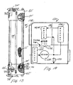
- FIGURE 1 is a diagrammatic illustration of a hydrogen peroxide vapor decontamination system in accordance with the present invention;
- FIGURE 2 is a side-view of the peroxy vapor generation system;
- FIGURE 3 is an end-view of the system of FIGURE 2;
- FIGURE 4 is a top view of the vaporizer unit and disposable dryer cartridge embodiment of FIGURES 2 and 3;
- FIGURE 5 is an enlarged view of the desiccant cartridge of FIGURES 2-4;
- FIGURE 6 is an enlarged sectional view of an end portion of the cartridge of FIGURE 5;
- FIGURE 7 is a side-sectional view of the desiccant cartridge receiving assembly of FIGURES 2-4;
- FIGURE 8 is a front view of an upper portion of the assembly of FIGURE 7;
- FIGURE 9 is a top view of the assembly of FIGURE 7;
- FIGURE 10 is an side view of the vaporizer system of FIGURE 2 with an alternate, reusable dryer;
- FIGURE 11 is an end view of the alternate embodiment of FIGURE 10;
- FIGURE 12 is a top view of the vaporizer unit and reusable dryer cartridge embodiment of FIGURES 10 and 11 with front access panel doors partially open;
- FIGURE 13 is a side sectional view of the reusable dryer cartridge of FIGURES 10-12; and
- FIGURE 14 is a diagrammatic illustration of a regenerator unit for the cartridge of FIGURES 10-13.
-
- With reference to FIGURES 1, 2, 3, and 4, a
vapor generation unit 10 vaporizes a peroxy solution from asolution source 12 and entrains the vapor in dry air which has been dried by adryer 14. The dry air and vapor are conveyed to a treatment chamber, such as an isolator 16. - In the preferred embodiment, the peroxy solution source is a container or cartridge of hydrogen peroxide in water solution which is received in a
cartridge interface 20. Once in the cartridge interface, the cartridge is interconnected with a dip tube assembly for withdrawing the solution. Although a solution of hydrogen peroxide in water vapor is preferred, other solutions are contemplated, such as peracetic acid and water, other peroxy compounds and water, peroxy compounds in alcohol and water, and the like. In a preferred embodiment, the hydrogen peroxide and water solution is 35-50% hydrogen peroxide. - The vaporizer system includes an injection pump 22 which injects metered amounts of the peroxy solution into a vaporizer 24. The vaporizer, in a preferred embodiment, is a heated surface, such as a heated plate or the interior surface of a bore onto which the peroxy solution is sprayed or injected forming peroxy and water vapor. Dry air from the
dryer 14 is preheated in apreheater 26 and supplied to the vaporizer to entrain the hydrogen peroxide or other peroxy vapor and water vapor. The vapor entrained in the air is supplied to the treatment chamber 16. - In the treatment chamber, hydrogen peroxide vapor interacts with microbes and other contaminants in an oxidation reaction, deactivating the microbial material and leaving water vapor suspended in the air. Thus, with time, the concentration of hydrogen peroxide in the treatment chamber drops. To maintain the concentration of hydrogen peroxide vapor, a portion of the vapor and air is withdrawn and fed through a destroyer 28, such as copper pellets. The copper pellets catalytically degrade the remaining peroxide vapor into water vapor and oxygen. A
blower 30, which provides the motive force to move the air and vapor, pumps the air and water vapor to thedryer 14. Desiccant in the dryer absorbs the water vapor such that air of accurately predictable low humidity is discharged to thepreheater 26. In this manner, air of known humidity is supplied to the vaporizer, permitting the vaporizer to optimize the concentration of peroxide vapor without condensation. It will be noted that if a significant amount of unexpected water vapor were returned to the vaporizer, the additional vapor content of the saturated air could push the total vapor content of one or both of the peroxide and the water vapor beyond the condensation point. - In a preferred embodiment, the
dryer 14 includes adisposable desiccant cartridge 40 which is clamped into a clampingassembly 42. - With reference to FIGURES 5 and 6, the desiccant cartridge includes a
cylindrical tube 44 which is closed at either end withend caps 46 to form a cartridge of preselected length.Apertures 48 are defined centrally in each end cap to allow for the passage of gas into and out of the cartridge. The apertures are covered on the inside bydisks 50 of screening material to retain adesiccant 52. A water vaporimpermeable end seal 54 is adhesively adhered over an exterior of each opening to prevent the desiccant within the cartridge from absorbing water vapor before it is mounted in the clampingassembly 42. The aperture in each end is surrounded by aresilient gasket 56, such as a closed cell foam of a material which is inert to hydrogen peroxide or other circulated gases. - With reference again to FIGURES 2 and 3, and further reference to FIGURES 7, 8, and 9, the clamping
assembly 42 includes a pair ofend elements end pieces lower end element 62 includes an inlet connection port or bore 70 for interconnection with anoutlet nipple 72 of thevapor generator assembly 10. A latch assembly 74 engages alip 76 around the outlet nipple to maintain the clampingassembly 42 attached to the vapor generator. The inlet port includes an L-shaped passage terminating in anoutlet port 78 adjacent an inlet to the cartridge. The lower assembly has asmooth sealing face 80 surrounding theoutlet port 78 to provide an air-tight seal with thelower gasket 56. The lower assembly includes an upstanding,semi-circular guide portion 82 which receives and positions a lower end of the cartridge centered on theoutlet port 78. - The
upper element 60 includes anoutlet port 90 which is dimensioned to be received in a fluid-tight relationship with anipple 92 of an inlet port for dry gas on thevaporizer unit 10. Alatch assembly 94 locks the upper element to thenipple assembly lip 95. Theupper element 60 includes an L-shaped passage terminating in an inlet port 96. The inlet port 96 is surrounded by apiston 98 of larger diameter than thegasket 56 of the desiccant cartridge. The piston defines a smooth, polished sealing face 100 which forms a sealing relationship with the desiccant cartridge gasket. Thepiston 98 is retracted by pulling ahandle 102 toward the user, away from the vaporizingunit 10.Springs 104 bias the piston toward engagement with the gasket of the desiccant cartridge. When a desiccant cartridge is to be inserted, thehandle 102 is pushed away from the user, retracting the piston. This loosens the seal between the piston and the gasket of the used desiccant cartridge which is removed. The adhesive seals 54 of the new desiccant cartridge are removed and the desiccant cartridge is inserted into the latchingunit 72 until its rear surfaces engage thealignment surface 82 of thelower element 62 and a matchingalignment surface 106 of theupper element 60. Thehandle 102 is returned to the angled position allowing thesprings 104 to bias the sealing face 100 of thepiston 98 into a fluid-tight seal with the upper gasket of the desiccant cartridge. An O-ring 108 between thepiston 98 and theupper element 60 prevents vapor from passing between the piston and the upper end element. - In one preferred embodiment, the desiccant cartridge is sized in accordance with the anticipated hydrogen peroxide consumption. In one embodiment, the dryer is sized to accommodate the moisture from one cycle of the largest enclosure under worst case conditions. In this embodiment, the desiccant cartridge is replaced at the beginning of each cycle. In another embodiment, the desiccant cartridge is sized to absorb all of the water vapor that is generated by the contents of the hydrogen peroxide cartridge. In this embodiment, the desiccant cartridge is replaced each time the hydrogen peroxide cartridge is replaced. In another embodiment, the desiccant cartridge is sized to be able to hold the water generated by a plurality of the hydrogen peroxide cartridges. As yet another alternative, the desiccant cartridge includes an indicator which provides a visual indication that the cartridge is nearing saturation and should be replaced. As yet another alternative, the
vaporization unit 10 includes a moisture sensor which senses the humidity of the air entering the preheater. When the humidity starts to rise, the vaporization unit provides a visual or audio signal indicating that thedesiccant cartridge 40 is due for replacement. - As another alternative, the alignment surfaces 82, 106 have projections that are received in corresponding recess in the
cartridge 40 to ensure accurate alignment. In another alternative,mating surface 80 of thelower element 62 and the lower end cap have mating projections and recesses outside of the perimeter of thegasket 56 to assure alignment. When thehandle 102 is pushed to retract the piston, a pawl holds thepiston 98 retracted. A projection or element on the upper end cap interacts with the pawl directly or through a connecting linkage to release the piston only when the top of the cartridge is properly received to release the piston. As another option, cutters can be provided on thelower element 62 and thepiston 98 to open the end seals 54 when the cartridge is properly aligned. - With reference to FIGURES 10-13, in another embodiment, a dryer cartridge 40' is attached directly to the
nipples vaporizer unit 10. This embodiment includes a first or top element 60' and a second or lower end element 62' which are interconnected by a desiccant cylinder 44'. The upper end element includes a bore 90' with a gasket configured to receive theuppermost nipple 92 in a fluid-tight relationship; and the lower end element defines a lower well 70' and a gasket 56' configured to receive thelower nipple 72 in a fluid tight seal. A lower latch 74' engages the latching surface of thelower nipple 72 and an upper latch 94' engages the latch surface of theupper nipple 92. Screen elements 50' are disposed adjacent upper and lower outlets of the cartridge to contain a desiccant 52' therebetween. Aglass sight 110 enables the operator to view alower desiccant chamber 112 that is defined between a pair of the lower screens 50'. The color of the desiccant is an indication to the user whether or not a dryer has been regenerated. In the preferred embodiment, the desicacant turns clear soon after the dryer is put in use. The desiccant turns color (blue in this case) after regeneration. - Preferably, all components of the reusable desiccant cartridge are constructed of metal or other materials capable of withstanding repeated exposure to temperatures on the order of 150° C. Alternately, the cartridge can be a single use cartridge that is disposed after being used.
- When the desiccant cartridge is saturated or cannot hold the moisture generated by the next cycle to be run, the latches 74', 94' are released and the drying cartridge is removed and replaced with a regenerated cartridge. With reference to FIGURE 14, the saturated cartridge is placed in a regeneration unit 120. The regeneration unit includes nipples of the same size and spacing as
nipples HEPA filter 122 which removes airborne contaminants. A blower 124 blows the filtered air through aheater 126 to amanifold 128. The manifold is connected with one or more desiccant cartridges 40' which are to be regenerated. The heated air, heated to about 150° C., is blown through the desiccant entraining the absorbed water, and discharged to the atmosphere. After the desiccant is fully regenerated, as determined by measuring the temperature of the discharged air with a temperature switch 130, based on time, or other factors, the circulation of heated air through the desiccant is stopped and a cooling fan 132 is started. The cooling fan cools the desiccant cartridge back to room temperature while the ports of the cartridge remain closed. Alockable door 134 is released once the desiccant cartridges have cooled to a temperature that is safe to handle. The desiccant cartridges remain connected to the manifold to prevent the cooling air from entering the chambers where humidity from the cooling air would be absorbed.
Claims (15)
- A peroxy vapor system including a liquid peroxy solution interface (20) for receiving a source (12) of liquid peroxy solution, a vapor generation unit (10) for vaporizing the liquid peroxy solution and entraining the vapor in dry air for delivery to a point of use, and, a replaceable desiccant dryer (14) connected with the vapor generation unit for drying air of vapor prior to entraining the generated vapor in the dried air, characterized by:a pair of nipples (72, 92) for interconnecting the dryer (14) with the vapor generating unit (10);the dryer including:a desiccant chamber (44, 44') connected between end pieces (60, 62; 60', 62'), each end piece including a bore (70, 90; 70', 90') that receives one of the nipples in a fluid tight relationship, andat least one latch (74, 94; 74', 94') for latching the end pieces to the nipples.
- The system as set forth in claim 1 further characterized by the desiccant dryer (14) including a desiccant cartridge (40, 40') including:a tubular chamber (44, 44) having end closures (46, 60', 62') at either end;a desiccant material (52') in the chamber;an inlet aperture (48, 70) defined in one end closure and an outlet aperture (48, 90') defined in an opposite end closure;annular gaskets (56, 56') surrounding the apertures of the end closures.
- The system as set forth in claim 2 wherein the desiccant cartridge (40) is further characterized by:a screen element (50, 50') at each end aperture for retaining the desiccant material (52') within the tubular element (44, 44'); andremovable seals (54) closing the end apertures to prevent humidity from entering the desiccant dryer before the seals are removed.
- The peroxy vapor system as set forth in claim 2 further comprised by the end pieces (60, 62) including:a clamping assembly (42) which receives the desiccant cartridge (40).
- The system as set forth in claim 4 further characterized by the clamping assembly (42) including:a piston (98) mounted in one of the end pieces (60), the piston having a sealing face (100) for engaging a cartridge gasket (56) in a sealing relationship therewith;a second gasket sealing face (80) on the other end piece (62);a means (102) for retracting the piston (98) to facilitate removal of a saturated desiccant cartridge and receipt of an unsaturated desiccant cartridge.
- The system as set forth in claim 5 further characterized by the clamping assembly (42) further including:wherein the retracting means includes a manually operable lever (102) which is operated to move the piston against the springs retracting it.springs (104) for biasing the piston (98) into contact with the desiccant cartridge gasket (56); and,
- The system as set forth in either one of claims 5 and 6 further characterized by:an alignment bracket (82, 106) associated with each end element (60, 62) for aligning the desiccant cartridge gaskets with the gasket sealing faces (80, 100) of the clamping assembly.
- The system as set forth in any one of claims 1-7 further characterized by:the pair of nipples (72, 92) projecting from the vapor generation unit (10) and each nipple having a latch engaging surface (76, 95); andthe latches (74, 94; 74', 94') engaging the nipple latch surface for latching the end pieces to the nipples.
- The system as set forth in claim 1 further characterized by the desiccant chamber (44) being detachable from the end pieces (60, 62), the end pieces including:a piston (98) mounted in one of the end elements (60), the piston having a sealing face (100) for engaging one face of the desiccant chamber in a sealing relationship therewith;a second sealing face (80) on the other end element (62) ;a mechanism (102) for retracting the piston to facilitate removal of a saturated desiccant chamber and receipt of an unsaturated desiccant cartridge.
- The system as set forth in any one of claims 1-9 further characterized by:the desiccant chamber (44, 44') having a moisture absorption capacity matched to a volume of liquid in a peroxy solution cartridge (12) that is received in the liquid peroxy solution receiving interface (20).
- The system as set forth in any one of claims 1-10 further including:a regeneration oven (12) for regenerating saturated dryers.
- A method of using the system of any one of claims 1-11 further characterized by:connecting a source of liquid peroxy solution with an interface for a vaporizer;vaporizing the liquid peroxy solution and entraining the vapor in dry air;supplying the entrained vapor in air to a point of use;returning air and vapor from the point of use through a replaceable desiccant dryer; andwhen or before the desiccant dryer becomes saturated, replacing the desiccant dryer.
- The method as set forth in claim 12 wherein the desiccant dryer includes a cartridge and wherein the replacing step includes:disconnecting a saturated desiccant dryer cartridge from a flow path leading to the vaporizer; and,connecting an unsaturated desiccant dryer cartridge in the flow path to replace the saturated cartridge.
- The method as set forth claim 13 wherein the source of peroxy liquid includes a canister containing a preselected volume of peroxy liquid and further including:loading a amount of desiccant in the cartridge which is sufficient to absorb the preselected volume.
- The method as set forth in either one of claims 13 and 14 further including:regenerating the saturated desiccant cartridge;attaching temporary seals to openings into the cartridge to prevent the regenerated desiccant from absorbing moisture; and,before connecting the regenerated cartridge, opening the seals.
Applications Claiming Priority (3)
| Application Number | Priority Date | Filing Date | Title |
|---|---|---|---|
| US36112902P | 2002-02-28 | 2002-02-28 | |
| US361129P | 2002-02-28 | ||
| PCT/US2003/006501 WO2003072150A1 (en) | 2002-02-28 | 2003-02-28 | Hydrogen peroxide vapor system with replaceable desiccant cartridge |
Publications (2)
| Publication Number | Publication Date |
|---|---|
| EP1478409A1 EP1478409A1 (en) | 2004-11-24 |
| EP1478409B1 true EP1478409B1 (en) | 2005-06-08 |
Family
ID=27766250
Family Applications (1)
| Application Number | Title | Priority Date | Filing Date |
|---|---|---|---|
| EP03709423A Expired - Lifetime EP1478409B1 (en) | 2002-02-28 | 2003-02-28 | Hydrogen peroxide vapor system with replaceable desiccant cartridge |
Country Status (12)
| Country | Link |
|---|---|
| US (1) | US7431900B2 (en) |
| EP (1) | EP1478409B1 (en) |
| JP (3) | JP3905887B2 (en) |
| KR (1) | KR100591077B1 (en) |
| CN (1) | CN1281281C (en) |
| AT (1) | ATE297226T1 (en) |
| AU (1) | AU2003212483B8 (en) |
| CA (1) | CA2476472C (en) |
| DE (1) | DE60300820T2 (en) |
| ES (1) | ES2244925T3 (en) |
| HK (1) | HK1075626A1 (en) |
| WO (1) | WO2003072150A1 (en) |
Families Citing this family (40)
| Publication number | Priority date | Publication date | Assignee | Title |
|---|---|---|---|---|
| DE60300820T2 (en) * | 2002-02-28 | 2006-03-23 | Steris Inc., Temecula | DEVICE FOR PRODUCING HYDROGEN PEROXIDE VAPOR WITH EXCHANGEABLE DRY MATERIAL CARTRIDGE |
| US6990819B2 (en) * | 2003-08-07 | 2006-01-31 | Kendro Laboratory Products | Dryer system for the prevention of frost in an ultra low temperature freezer |
| JP2006288647A (en) * | 2005-04-08 | 2006-10-26 | Daikin Ind Ltd | Sterilizing system |
| CN101479019B (en) * | 2006-04-26 | 2013-01-30 | 色谱研究供应股份有限公司 | High capacity gas filter system with indicator |
| DE102006036476A1 (en) * | 2006-08-04 | 2008-02-07 | Khs Ag | filter cartridge |
| US7700056B2 (en) * | 2006-08-10 | 2010-04-20 | American Sterilizer Company | Modular decontamination system |
| US20070080613A1 (en) * | 2006-09-20 | 2007-04-12 | Sterlite Optical Technologies Ltd | Storage and transportation device for storing and transporting optical fiber preform and precursors thereof |
| WO2008109253A1 (en) * | 2007-03-06 | 2008-09-12 | Steris Inc. | Transportable decontamination unit and decontamination process |
| US7919059B2 (en) * | 2007-04-27 | 2011-04-05 | American Sterilizer Company | Vaporized hydrogen peroxide decontamination system with concentration adjustment mode |
| US8137440B2 (en) * | 2007-05-09 | 2012-03-20 | Protégé Enterprises | Dryer having structure for enhanced drying and method of use |
| US8668765B2 (en) | 2007-05-09 | 2014-03-11 | Protege Enterprises | Dryer having structure for enhanced drying efficiency and method of use |
| US8007717B2 (en) | 2007-08-14 | 2011-08-30 | American Sterilizer Company | Method and apparatus for decontaminating a region without dehumidification |
| US8899556B2 (en) * | 2007-11-15 | 2014-12-02 | Lawrence Livermore National Security, Llc. | Systems and methods for generation of hydrogen peroxide vapor |
| JP5410411B2 (en) * | 2008-02-26 | 2014-02-05 | パナソニック株式会社 | Desulfurizer, hydrogen generator, fuel cell power generation system, and desulfurizing agent cartridge |
| CN105289208A (en) | 2009-06-25 | 2016-02-03 | Vtu控股有限责任公司 | Method of use of an ionic liquid and device for sorption of a gas |
| EP2278325A1 (en) * | 2009-07-13 | 2011-01-26 | Spark Holland B.V. | Flow through cartridge for selecting an analyte online with high performance liquid chromatography |
| DE102009060512A1 (en) | 2009-12-23 | 2011-07-07 | Metall + Plastic GmbH, 78315 | Flash steam generator and arrangement with flash steam generator |
| US20110232321A1 (en) * | 2010-03-24 | 2011-09-29 | Whirlpool Corporation | Atomization of food preservation solution |
| US8828126B2 (en) * | 2011-02-04 | 2014-09-09 | Leco Corporation | Removable final scrubber tube |
| CN103732660A (en) | 2011-06-03 | 2014-04-16 | 沙伯基础创新塑料知识产权有限公司 | Sterilized polyetherimide articles |
| KR101913825B1 (en) | 2011-06-03 | 2018-10-31 | 사빅 글로벌 테크놀러지스 비.브이. | Sterilized polyetherimide/polyphenylene ether sulfone articles |
| US10307499B2 (en) | 2011-09-22 | 2019-06-04 | Bürkert Contromatic Corp. | Devices, systems and methods for zone sterilization |
| US9855358B2 (en) | 2011-09-22 | 2018-01-02 | Bürkert Contromatic Corp. | Devices, systems and methods for zone sterilization |
| US10814026B2 (en) | 2011-09-22 | 2020-10-27 | Bürkert Contromatic Corp. | Devices, systems and methods for zone sterilization |
| US9125960B2 (en) * | 2011-09-22 | 2015-09-08 | Bürkert Contromatic Corp. | Devices, systems and methods for zone sterilization |
| US8992853B2 (en) * | 2011-09-22 | 2015-03-31 | Bürkert Contromatic Corp. | Devices, systems and methods for localized sterilization |
| US8686355B2 (en) * | 2012-03-08 | 2014-04-01 | Morpho Detection, Llc | Detection system assembly, dryer cartridge, and regenerator and methods for making and using the same |
| CN103041415B (en) * | 2012-12-07 | 2014-07-02 | 成都老肯科技股份有限公司 | Cabinet door for hydrogen peroxide low-temperature plasma sterilizer |
| ES2699305T3 (en) | 2013-12-30 | 2019-02-08 | American Sterilizer Co | Portable decontamination unit |
| WO2016025870A1 (en) | 2014-08-15 | 2016-02-18 | Global Oil EOR Systems, Ltd. | Hydrogen peroxide steam generator for oilfield applications |
| US10576178B2 (en) | 2014-10-22 | 2020-03-03 | Helder da Costa Goncalves | Sterilization device using hydrogen peroxide and ozone vaporized and combined through multiple capillary tubes |
| DE102015102491A1 (en) | 2015-02-20 | 2016-08-25 | Metall + Plastic Gmbh | Flash evaporator arrangement with flash evaporator and operating method |
| US10049868B2 (en) | 2016-12-06 | 2018-08-14 | Rapiscan Systems, Inc. | Apparatus for detecting constituents in a sample and method of using the same |
| US10458885B2 (en) | 2017-03-31 | 2019-10-29 | Rapiscan Systems, Inc. | Rapid desorber heating and cooling for trace detection |
| GB2561601A (en) * | 2017-04-20 | 2018-10-24 | Deutsche Post Ag | Process for aseptic filling of beverage packaging comprising an interior drinking straw |
| US11235329B2 (en) | 2017-08-10 | 2022-02-01 | Rapiscan Systems, Inc. | Systems and methods for substance detection using thermally stable collection devices |
| CN111630624A (en) | 2018-01-24 | 2020-09-04 | 拉皮斯坎系统股份有限公司 | Surface layer disruption and ionization using extreme ultraviolet radiation source |
| US11609214B2 (en) | 2019-07-31 | 2023-03-21 | Rapiscan Systems, Inc. | Systems and methods for improving detection accuracy in electronic trace detectors |
| US20220307708A1 (en) * | 2021-03-25 | 2022-09-29 | Vektra Systems LLC | Desiccant air purification device |
| CN117046297B (en) * | 2023-10-12 | 2024-01-02 | 常州宏川石化仓储有限公司 | Dry and wet waste gas conveying mechanism, vocs waste gas recycling system and recycling method |
Family Cites Families (24)
| Publication number | Priority date | Publication date | Assignee | Title |
|---|---|---|---|---|
| US2572311A (en) * | 1950-03-08 | 1951-10-23 | Francis W Burd | Moisture eliminating device for compressed-air systems |
| US3338032A (en) * | 1966-04-12 | 1967-08-29 | Robert M Siewert | Dehumidifier desiccant cartridge |
| US3552034A (en) * | 1968-06-17 | 1971-01-05 | Universal Dynamics Corp | Particle drying apparatus |
| US3705480A (en) * | 1970-02-06 | 1972-12-12 | Wallace M Wireman | Dehydrator for gaseous fluids |
| US4131442A (en) * | 1977-04-29 | 1978-12-26 | Graham-White Sales Corporation | Pneumatic compactor for particulate desiccant |
| EP0065019A1 (en) * | 1981-05-15 | 1982-11-24 | Bauer Kompressoren Gmbh | Method for the determination of the degree of saturation of a drying-cartridge, suitable for the drying of humid gases, and devices for carrying out the method |
| US4594082A (en) * | 1984-11-19 | 1986-06-10 | Harris Corporation | Dehydrating air-filtering apparatus |
| JPS6339414U (en) * | 1986-08-29 | 1988-03-14 | ||
| US4745772A (en) * | 1987-04-20 | 1988-05-24 | Ferris James E | Air conditioner auxiliary filter/drier refrigerant and chemical additive transfer device |
| US4909999A (en) * | 1987-07-06 | 1990-03-20 | American Sterilizer Company | Flow-through vapor phase sterilization system |
| JPH01139121A (en) * | 1987-11-25 | 1989-05-31 | Hitachi Ltd | Desiccating agent regenerator |
| DE3903711A1 (en) * | 1989-02-08 | 1990-08-16 | Sued Chemie Ag | DRYING CARTRIDGE |
| US4966697A (en) * | 1989-06-13 | 1990-10-30 | Rosaen Nils N | Fluid filter retaining device |
| US5173258A (en) * | 1989-10-11 | 1992-12-22 | American Sterilizer Company | Recirculation, vapor and humidity control in a sealable enclosure |
| US5114003A (en) * | 1991-03-28 | 1992-05-19 | E. I. Du Pont De Nemours And Company | Tablet vial with desiccant in bottom |
| GB9224162D0 (en) * | 1992-11-18 | 1993-01-06 | Bendix Ltd | Gas drying apparatus |
| DE4243816A1 (en) * | 1992-12-23 | 1994-06-30 | Zeolith Tech | Sorbent cartridge |
| GB9523717D0 (en) | 1995-11-20 | 1996-01-24 | Mdh Ltd | Method and apparatus for hydrogen peroxide vapour sterilization |
| US5876664A (en) * | 1996-06-14 | 1999-03-02 | American Sterilizer Company | Continuous-operation, closed loop decontamination system and method |
| US5792435A (en) * | 1997-04-08 | 1998-08-11 | Steris Corporation | Vapor phase decontaminant isolator apparatus with integral vapor phase decontaminant generator system |
| US6077480A (en) * | 1997-06-19 | 2000-06-20 | Steris Corporation | Multiple flashpoint vaporization system |
| US6488902B1 (en) * | 1997-11-03 | 2002-12-03 | Ethicon, Inc. | Sterilizer exhaust gas inactivation |
| FR2778584B1 (en) * | 1998-05-15 | 2000-08-04 | Sextant Avionique | DESICCATOR ENCLOSURE |
| DE60300820T2 (en) * | 2002-02-28 | 2006-03-23 | Steris Inc., Temecula | DEVICE FOR PRODUCING HYDROGEN PEROXIDE VAPOR WITH EXCHANGEABLE DRY MATERIAL CARTRIDGE |
-
2003
- 2003-02-28 DE DE60300820T patent/DE60300820T2/en not_active Expired - Lifetime
- 2003-02-28 CA CA002476472A patent/CA2476472C/en not_active Expired - Lifetime
- 2003-02-28 ES ES03709423T patent/ES2244925T3/en not_active Expired - Lifetime
- 2003-02-28 WO PCT/US2003/006501 patent/WO2003072150A1/en active IP Right Grant
- 2003-02-28 AT AT03709423T patent/ATE297226T1/en not_active IP Right Cessation
- 2003-02-28 EP EP03709423A patent/EP1478409B1/en not_active Expired - Lifetime
- 2003-02-28 CN CNB038049058A patent/CN1281281C/en not_active Expired - Fee Related
- 2003-02-28 JP JP2003570893A patent/JP3905887B2/en not_active Expired - Lifetime
- 2003-02-28 KR KR1020047013496A patent/KR100591077B1/en not_active IP Right Cessation
- 2003-02-28 US US10/377,557 patent/US7431900B2/en active Active
- 2003-02-28 AU AU2003212483A patent/AU2003212483B8/en not_active Expired
-
2005
- 2005-10-10 HK HK05108975A patent/HK1075626A1/en not_active IP Right Cessation
-
2006
- 2006-11-16 JP JP2006310793A patent/JP4533879B2/en not_active Expired - Lifetime
-
2010
- 2010-03-04 JP JP2010048253A patent/JP2010158677A/en not_active Withdrawn
Also Published As
| Publication number | Publication date |
|---|---|
| US7431900B2 (en) | 2008-10-07 |
| HK1075626A1 (en) | 2005-12-23 |
| AU2003212483B2 (en) | 2005-11-10 |
| CA2476472C (en) | 2007-08-07 |
| DE60300820T2 (en) | 2006-03-23 |
| JP3905887B2 (en) | 2007-04-18 |
| KR20040084947A (en) | 2004-10-06 |
| EP1478409A1 (en) | 2004-11-24 |
| CA2476472A1 (en) | 2003-09-04 |
| JP4533879B2 (en) | 2010-09-01 |
| KR100591077B1 (en) | 2006-06-19 |
| CN1638815A (en) | 2005-07-13 |
| AU2003212483B8 (en) | 2006-03-30 |
| JP2007038030A (en) | 2007-02-15 |
| US20030164091A1 (en) | 2003-09-04 |
| DE60300820D1 (en) | 2005-07-14 |
| CN1281281C (en) | 2006-10-25 |
| WO2003072150A1 (en) | 2003-09-04 |
| JP2005518839A (en) | 2005-06-30 |
| JP2010158677A (en) | 2010-07-22 |
| ES2244925T3 (en) | 2005-12-16 |
| ATE297226T1 (en) | 2005-06-15 |
| AU2003212483A1 (en) | 2003-09-09 |
Similar Documents
| Publication | Publication Date | Title |
|---|---|---|
| EP1478409B1 (en) | Hydrogen peroxide vapor system with replaceable desiccant cartridge | |
| US20210369899A1 (en) | Sterilization Method and Apparatus | |
| EP0298599B1 (en) | Treatment of materials | |
| JP6104473B2 (en) | Portable decontamination unit | |
| US5482541A (en) | Sorption cartridge | |
| WO2003068274A2 (en) | Sterilizing or disinfecting device | |
| CN113600588A (en) | Radioactive synthesis experimental device capable of self-purifying and monitoring and experimental fume hood |
Legal Events
| Date | Code | Title | Description |
|---|---|---|---|
| PUAI | Public reference made under article 153(3) epc to a published international application that has entered the european phase |
Free format text: ORIGINAL CODE: 0009012 |
|
| GRAP | Despatch of communication of intention to grant a patent |
Free format text: ORIGINAL CODE: EPIDOSNIGR1 |
|
| 17P | Request for examination filed |
Effective date: 20040826 |
|
| AK | Designated contracting states |
Kind code of ref document: A1 Designated state(s): AT BE BG CH CY CZ DE DK EE ES FI FR GB GR HU IE IT LI LU MC NL PT SE SI SK TR |
|
| AX | Request for extension of the european patent |
Extension state: AL LT LV MK RO |
|
| GRAS | Grant fee paid |
Free format text: ORIGINAL CODE: EPIDOSNIGR3 |
|
| GRAA | (expected) grant |
Free format text: ORIGINAL CODE: 0009210 |
|
| AK | Designated contracting states |
Kind code of ref document: B1 Designated state(s): AT BE BG CH CY CZ DE DK EE ES FI FR GB GR HU IE IT LI LU MC NL PT SE SI SK TR |
|
| PG25 | Lapsed in a contracting state [announced via postgrant information from national office to epo] |
Ref country code: SI Free format text: LAPSE BECAUSE OF FAILURE TO SUBMIT A TRANSLATION OF THE DESCRIPTION OR TO PAY THE FEE WITHIN THE PRESCRIBED TIME-LIMIT Effective date: 20050608 Ref country code: SK Free format text: LAPSE BECAUSE OF FAILURE TO SUBMIT A TRANSLATION OF THE DESCRIPTION OR TO PAY THE FEE WITHIN THE PRESCRIBED TIME-LIMIT Effective date: 20050608 Ref country code: TR Free format text: LAPSE BECAUSE OF FAILURE TO SUBMIT A TRANSLATION OF THE DESCRIPTION OR TO PAY THE FEE WITHIN THE PRESCRIBED TIME-LIMIT Effective date: 20050608 Ref country code: EE Free format text: LAPSE BECAUSE OF FAILURE TO SUBMIT A TRANSLATION OF THE DESCRIPTION OR TO PAY THE FEE WITHIN THE PRESCRIBED TIME-LIMIT Effective date: 20050608 Ref country code: AT Free format text: LAPSE BECAUSE OF FAILURE TO SUBMIT A TRANSLATION OF THE DESCRIPTION OR TO PAY THE FEE WITHIN THE PRESCRIBED TIME-LIMIT Effective date: 20050608 Ref country code: NL Free format text: LAPSE BECAUSE OF FAILURE TO SUBMIT A TRANSLATION OF THE DESCRIPTION OR TO PAY THE FEE WITHIN THE PRESCRIBED TIME-LIMIT Effective date: 20050608 Ref country code: CZ Free format text: LAPSE BECAUSE OF FAILURE TO SUBMIT A TRANSLATION OF THE DESCRIPTION OR TO PAY THE FEE WITHIN THE PRESCRIBED TIME-LIMIT Effective date: 20050608 |
|
| REG | Reference to a national code |
Ref country code: GB Ref legal event code: FG4D |
|
| REG | Reference to a national code |
Ref country code: CH Ref legal event code: EP |
|
| REF | Corresponds to: |
Ref document number: 60300820 Country of ref document: DE Date of ref document: 20050714 Kind code of ref document: P |
|
| REG | Reference to a national code |
Ref country code: IE Ref legal event code: FG4D |
|
| REG | Reference to a national code |
Ref country code: SE Ref legal event code: TRGR |
|
| PG25 | Lapsed in a contracting state [announced via postgrant information from national office to epo] |
Ref country code: BG Free format text: LAPSE BECAUSE OF FAILURE TO SUBMIT A TRANSLATION OF THE DESCRIPTION OR TO PAY THE FEE WITHIN THE PRESCRIBED TIME-LIMIT Effective date: 20050908 Ref country code: GR Free format text: LAPSE BECAUSE OF FAILURE TO SUBMIT A TRANSLATION OF THE DESCRIPTION OR TO PAY THE FEE WITHIN THE PRESCRIBED TIME-LIMIT Effective date: 20050908 Ref country code: DK Free format text: LAPSE BECAUSE OF FAILURE TO SUBMIT A TRANSLATION OF THE DESCRIPTION OR TO PAY THE FEE WITHIN THE PRESCRIBED TIME-LIMIT Effective date: 20050908 |
|
| PG25 | Lapsed in a contracting state [announced via postgrant information from national office to epo] |
Ref country code: PT Free format text: LAPSE BECAUSE OF FAILURE TO SUBMIT A TRANSLATION OF THE DESCRIPTION OR TO PAY THE FEE WITHIN THE PRESCRIBED TIME-LIMIT Effective date: 20051114 |
|
| NLV1 | Nl: lapsed or annulled due to failure to fulfill the requirements of art. 29p and 29m of the patents act | ||
| PG25 | Lapsed in a contracting state [announced via postgrant information from national office to epo] |
Ref country code: HU Free format text: LAPSE BECAUSE OF FAILURE TO SUBMIT A TRANSLATION OF THE DESCRIPTION OR TO PAY THE FEE WITHIN THE PRESCRIBED TIME-LIMIT Effective date: 20051209 |
|
| REG | Reference to a national code |
Ref country code: CH Ref legal event code: NV Representative=s name: AMMANN PATENTANWAELTE AG BERN |
|
| REG | Reference to a national code |
Ref country code: ES Ref legal event code: FG2A Ref document number: 2244925 Country of ref document: ES Kind code of ref document: T3 |
|
| PG25 | Lapsed in a contracting state [announced via postgrant information from national office to epo] |
Ref country code: MC Free format text: LAPSE BECAUSE OF NON-PAYMENT OF DUE FEES Effective date: 20060228 Ref country code: LU Free format text: LAPSE BECAUSE OF NON-PAYMENT OF DUE FEES Effective date: 20060228 |
|
| ET | Fr: translation filed | ||
| PLBE | No opposition filed within time limit |
Free format text: ORIGINAL CODE: 0009261 |
|
| STAA | Information on the status of an ep patent application or granted ep patent |
Free format text: STATUS: NO OPPOSITION FILED WITHIN TIME LIMIT |
|
| 26N | No opposition filed |
Effective date: 20060309 |
|
| BECA | Be: change of holder's address |
Owner name: AMERICAN STERILIZER CY5960 HEISLEY ROAD, US - MENT Effective date: 20050608 |
|
| BECH | Be: change of holder |
Owner name: AMERICAN STERILIZER CY Effective date: 20050608 |
|
| PGFP | Annual fee paid to national office [announced via postgrant information from national office to epo] |
Ref country code: CH Payment date: 20080228 Year of fee payment: 6 |
|
| PGFP | Annual fee paid to national office [announced via postgrant information from national office to epo] |
Ref country code: FI Payment date: 20080228 Year of fee payment: 6 Ref country code: IE Payment date: 20080227 Year of fee payment: 6 Ref country code: SE Payment date: 20080227 Year of fee payment: 6 |
|
| PGFP | Annual fee paid to national office [announced via postgrant information from national office to epo] |
Ref country code: BE Payment date: 20080306 Year of fee payment: 6 |
|
| REG | Reference to a national code |
Ref country code: CH Ref legal event code: PUE Owner name: AMERICAN STERILIZER COMPANY Free format text: STERIS, INC.#43425 BUSINESS PARK DRIVE#TEMECULA, CALIFORNIA 92590 (US) -TRANSFER TO- AMERICAN STERILIZER COMPANY#5960 HEISLEY ROAD#MENTOR, OH 44060 (US) |
|
| REG | Reference to a national code |
Ref country code: FR Ref legal event code: TP |
|
| PG25 | Lapsed in a contracting state [announced via postgrant information from national office to epo] |
Ref country code: CY Free format text: LAPSE BECAUSE OF FAILURE TO SUBMIT A TRANSLATION OF THE DESCRIPTION OR TO PAY THE FEE WITHIN THE PRESCRIBED TIME-LIMIT Effective date: 20050608 |
|
| BERE | Be: lapsed |
Owner name: AMERICAN STERILIZER CY Effective date: 20090228 |
|
| REG | Reference to a national code |
Ref country code: CH Ref legal event code: PL |
|
| PG25 | Lapsed in a contracting state [announced via postgrant information from national office to epo] |
Ref country code: CH Free format text: LAPSE BECAUSE OF NON-PAYMENT OF DUE FEES Effective date: 20090228 Ref country code: LI Free format text: LAPSE BECAUSE OF NON-PAYMENT OF DUE FEES Effective date: 20090228 Ref country code: FI Free format text: LAPSE BECAUSE OF NON-PAYMENT OF DUE FEES Effective date: 20090228 |
|
| EUG | Se: european patent has lapsed | ||
| REG | Reference to a national code |
Ref country code: IE Ref legal event code: MM4A |
|
| PG25 | Lapsed in a contracting state [announced via postgrant information from national office to epo] |
Ref country code: IE Free format text: LAPSE BECAUSE OF NON-PAYMENT OF DUE FEES Effective date: 20090302 |
|
| PG25 | Lapsed in a contracting state [announced via postgrant information from national office to epo] |
Ref country code: BE Free format text: LAPSE BECAUSE OF NON-PAYMENT OF DUE FEES Effective date: 20090228 |
|
| PG25 | Lapsed in a contracting state [announced via postgrant information from national office to epo] |
Ref country code: SE Free format text: LAPSE BECAUSE OF NON-PAYMENT OF DUE FEES Effective date: 20090301 |
|
| REG | Reference to a national code |
Ref country code: FR Ref legal event code: PLFP Year of fee payment: 14 |
|
| REG | Reference to a national code |
Ref country code: FR Ref legal event code: PLFP Year of fee payment: 15 |
|
| REG | Reference to a national code |
Ref country code: FR Ref legal event code: PLFP Year of fee payment: 16 |
|
| REG | Reference to a national code |
Ref country code: DE Ref legal event code: R082 Ref document number: 60300820 Country of ref document: DE Representative=s name: ETL WABLAT & KOLLEGEN PATENT- UND RECHTSANWALT, DE Ref country code: DE Ref legal event code: R082 Ref document number: 60300820 Country of ref document: DE Representative=s name: ETL IP PATENT- UND RECHTSANWALTSGESELLSCHAFT M, DE |
|
| REG | Reference to a national code |
Ref country code: DE Ref legal event code: R082 Ref document number: 60300820 Country of ref document: DE Representative=s name: ETL IP PATENT- UND RECHTSANWALTSGESELLSCHAFT M, DE |
|
| PGFP | Annual fee paid to national office [announced via postgrant information from national office to epo] |
Ref country code: GB Payment date: 20220225 Year of fee payment: 20 Ref country code: DE Payment date: 20220225 Year of fee payment: 20 |
|
| PGFP | Annual fee paid to national office [announced via postgrant information from national office to epo] |
Ref country code: IT Payment date: 20220222 Year of fee payment: 20 Ref country code: FR Payment date: 20220223 Year of fee payment: 20 Ref country code: ES Payment date: 20220301 Year of fee payment: 20 |
|
| REG | Reference to a national code |
Ref country code: DE Ref legal event code: R071 Ref document number: 60300820 Country of ref document: DE |
|
| REG | Reference to a national code |
Ref country code: GB Ref legal event code: PE20 Expiry date: 20230227 |
|
| REG | Reference to a national code |
Ref country code: ES Ref legal event code: FD2A Effective date: 20230428 |
|
| PG25 | Lapsed in a contracting state [announced via postgrant information from national office to epo] |
Ref country code: GB Free format text: LAPSE BECAUSE OF EXPIRATION OF PROTECTION Effective date: 20230227 |
|
| PG25 | Lapsed in a contracting state [announced via postgrant information from national office to epo] |
Ref country code: ES Free format text: LAPSE BECAUSE OF EXPIRATION OF PROTECTION Effective date: 20230301 |