EP1478048A2 - Antenna for cellular phone - Google Patents
Antenna for cellular phone Download PDFInfo
- Publication number
- EP1478048A2 EP1478048A2 EP04010759A EP04010759A EP1478048A2 EP 1478048 A2 EP1478048 A2 EP 1478048A2 EP 04010759 A EP04010759 A EP 04010759A EP 04010759 A EP04010759 A EP 04010759A EP 1478048 A2 EP1478048 A2 EP 1478048A2
- Authority
- EP
- European Patent Office
- Prior art keywords
- antenna
- cellular phone
- groove
- protrusion
- connector
- Prior art date
- Legal status (The legal status is an assumption and is not a legal conclusion. Google has not performed a legal analysis and makes no representation as to the accuracy of the status listed.)
- Withdrawn
Links
Images


Classifications
-
- H—ELECTRICITY
- H01—ELECTRIC ELEMENTS
- H01Q—ANTENNAS, i.e. RADIO AERIALS
- H01Q1/00—Details of, or arrangements associated with, antennas
- H01Q1/08—Means for collapsing antennas or parts thereof
- H01Q1/088—Quick-releasable antenna elements
-
- H—ELECTRICITY
- H01—ELECTRIC ELEMENTS
- H01Q—ANTENNAS, i.e. RADIO AERIALS
- H01Q1/00—Details of, or arrangements associated with, antennas
- H01Q1/12—Supports; Mounting means
- H01Q1/22—Supports; Mounting means by structural association with other equipment or articles
- H01Q1/24—Supports; Mounting means by structural association with other equipment or articles with receiving set
- H01Q1/241—Supports; Mounting means by structural association with other equipment or articles with receiving set used in mobile communications, e.g. GSM
- H01Q1/242—Supports; Mounting means by structural association with other equipment or articles with receiving set used in mobile communications, e.g. GSM specially adapted for hand-held use
Definitions
- the present invention relates to an antenna for a cellular phone, and in particular to an antenna for a cellular phone that is stably fixed to a body of a cellular phone wherein assembling and disassembling procedures are easy for thereby achieving an easier maintenance.
- a cellular phone is an apparatus so that people can freely communicate based on a wireless communication technology while people are moving.
- communication devices such as a cellular phone, a PCS phone, a digital phone, etc.
- the cellular phone includes an antenna for a signal transmission and receiving operation.
- the antenna of the cellular phone is generally classified into a fixed type antenna of which the length is not changed because it is fixed to the body of the cellular phone, and an extendable antenna in which a rod antenna is extended and contracted from an antenna housing fixed to the body of the cellular phone. W/hen designing the cellular phone, one between the fixed antenna and the extendable antenna is selected based on the function and design.
- Figure 1 is a perspective and partial cross sectional view illustrating a conventional antenna of a cellular phone.
- an antenna 10 in the cellular phone 1 having an extendable antenna, includes an antenna housing 11 protruded from an upper side of a lower frame 14a of a cell phone body 14, a rod antenna 15 extended or contacted into the housing 11, and an antenna holder 16 installed within the upper side of the lower frame 14a of the cell phone body 14.
- a metallic antenna holder 16 is installed in the upper side of the lower frame 14a of the cell phone body 14, wherein the antenna holder 16 is connected with a transmission and receiving circuit (not shown) of the cell phone body 14 for thereby receiving signals.
- the antenna housing 11 includes an antenna support part 12 having a circular cross section, and a metallic antenna connector 13 integrally formed in the lower side of the same.
- a threaded part 13a is formed in an outer side of the antenna connector 13.
- the antenna housing 11 is fixed to the cell phone body 14 in such a manner that the threaded part 13a of the antenna connector 13 is threaded to the antenna holder 16.
- the rod antenna 15 vertically passes through the antenna housing 11 and is extendable through the same.
- a contacting part (not shown) of the lower end portion of the rod antenna 15 contacts with the antenna connector 13 and is electrically connected with the body transmission and receiving circuit (not shown) for thereby achieving signal transmission and receiving operations.
- the antenna housing 11 When repairing the antenna in the case that the rod antenna 15 is broken, the antenna housing 11 is rotated, and the antenna housing 11 is separated from the cell phone body 14, and a new unit formed of the rod antenna 15 and the antenna housing 11 is assembled easily.
- the shape of the cross section of the antenna housing may be diversified.
- the cross section may be formed in a rectangular shape, a diamond shape, an elliptical shape, etc.
- Figure 2 is a perspective and partial assembling view illustrating a conventional antenna of a cellular phone.
- the antenna 20 includes an antenna housing 21 protruded from an upper side of the lower frame 27a of a cellular phone body 27, a rod antenna 25 extendable from the housing 21, and an antenna holder (not shown) installed in the upper side of the body lower frame 27a.
- the antenna housing 21 includes an antenna support part 22 having a rectangular cross section, and a metallic antenna connector 23 integrally formed in a lower side of the antenna support part 22.
- the antenna connector is formed in a cylindrical shape and has a threaded part in an outer side.
- the antenna connector 23 is formed in an edge shaped engaging structure and is engaged to the cellular phone body 27 by an edge engaging method.
- the construction that the antenna housing 21 is engaged to the cellular phone body 27 is changed based on an engaged state of the antenna support part 22 and the antenna connector 23. Namely, when viewing front side of the cellular phone, the antenna housing 21 may be viewed in a twisted shape. The above outer look is not good. Therefore, in the antenna having a certain cross section that is not a circular shape, there is a design limit that the antenna connector should be fabricated in an edge shape.
- the repairing operation of the antenna is performed through a very complicated procedure. Namely, in the repairing operation of the antenna 20, the battery pack 26 is first removed, and the lower frame 27a of the cellular phone body 27 is disassembled. The edge shaped antenna connector 23 positioned in the inner side of the cellular phone body 27 is exposed to the outside, and then the antenna 20 is exchanged.
- the lower frame 27a and the upper frame 27b are engaged by various bolts (not shown) and protect various electronic parts such as a transmission and receiving circuit (not shown) installed in the interior of the cellular phone body 27, so that it is impossible for user to easily disassemble the parts. Therefore, the user pays additional repairing charges to a service center.
- a second error may occur in various connection apparatuses of the transmission and receiving circuit and the cellular phone.
- a buffering groove is formed in the antenna holder for preventing the antenna from being escaped from the cellular phone body or from being damaged.
- the antenna holder is integrally formed in the cellular phone body.
- an object of the present invention to provide an antenna for a cellular phone that is stably fixed to a cellular phone body, and an assembling and disassembling procedure are easy, and an antenna exchanging operation is conveniently performed.
- a protrusion part is formed in an antenna connector for supporting a rod antenna, and the protrusion part is inserted into a guide groove part of the antenna holder inserted into the interior of the body of the cellular phone.
- the antenna is conveniently engaged or disassembled from the body of the cellular phone by rotating the antenna housing.
- an antenna for a cellular phone comprising an antenna holder having a guide groove part and engaged in a body of a cellular phone; an antenna housing that is formed of an antenna connector having a protrusion part engaged to the guide groove part and fixedly inserted into the antenna holder, and an antenna support part integrally formed in the antenna connector; and a rod antenna that passes through the antenna connector and the antenna support part, respectively, in such a manner that the rod antenna is extendable from the body of the cellular phone.
- the antenna holder includes a guide groove part formed of an entry groove formed in a hollow cylindrical shape in such a manner that the protrusion is inserted into one side of an upper hole; an entry straight line groove horizontally extended from the entry groove; a slant guiding groove downwardly extended from the entry straight line groove; and a fixed straight line groove horizontally extended from the slant guiding groove.
- Two guide groove parts are formed in the antenna holder, and two protrusion parts engaged with the guide groove part are formed in the antenna connector.
- An elastic protrusion is formed in a lower side of the antenna support part of the antenna housing, and the elastic protrusion part contacts with an outer side of the body of the cellular phone, so that the antenna housing is stably fixed to the body of the cellular phone.
- a fixed groove is formed in the fixed straight line groove of the guide groove part of the antenna holder wherein the protrusion part of the antenna connector is fixedly inserted into one of the fixed groove.
- an antenna for a cellular phone that includes an antenna housing formed of a metallic antenna connector electrically connected with a transmission and receiving circuit in the interior of a body of a cellular phone and having a vertical through hole in the interior of the body so that a rod antenna is upwardly expendable, and an antenna support part that is formed of a synthetic resin or rubber material and integrally formed in an outer side of the antenna connector by an insert injection method so that a cross sectional shape is line-symmetrical line an elliptical shape or a rectangular shape, an antenna engaging part formed in one side of the upper side of the body so that the antenna housing is engaged to the body of the cellular phone, and a metallic antenna holder installed in a hollow mounting groove formed in the antenna engaging part, there is provided an improved antenna for a cellular phone, comprising a protrusion step vertically formed in the upper side of the antenna holder at both sides of the same in such a manner that a downwardly slanted groove is formed from one side to the other side or from the other
- the height of the protrusion step is within a range of 0.2mm through 1 mm.
- the antenna 310 for a cellular phone is installed at a certain portion of a body 301 of a cellular phone 300 wherein a rod antenna 315 is extendable in an upward direction of the body 301.
- the antenna 310 includes an antenna holder 316 installed in the cellular phone body 301, an antenna housing 311 engaged to the antenna holder 316, and a rod antenna 315 passing through the antenna housing 311.
- the antenna holder 316 is formed in a metallic hollow cylindrical shape and includes a guide groove part 320 in a wall surface and is engaged to a lower frame 301a of the body 301 and is connected with a transmission and receiving circuit (not shown) of the body 301 for thereby performing a signal transmitting and receiving operation.
- the antenna housing 311 includes an antenna support part 312 having a rectangular cross section, and an antenna connector 313 integrally formed in the support part 312.
- the antenna part 312 is formed of an electrically insulated material and is integrally formed in the metallic antenna connector 313 by an injection method.
- the antenna support part 312 may have a rectangular cross section and may have a certain cross section shape such as a diamond shape, an elliptical shape etc. in consideration with the entire design of the cellular phone.
- the antenna housing 311 engaged with the support part 312 and the antenna connector 313 has a through hole (not shown) in a vertical direction, and a rod antenna 315 passes through the through hole based on a sliding movement method.
- An elastic protrusion part 312a contacting with the body 301 is formed in a lower side of the support part 312, so that the antenna housing 311 is stably fixed with respect to the body 301.
- a protrusion part 313a is formed in an outer side of the antenna connector 313 and is engaged with a guide groove part 320 of the antenna holder 316.
- the protrusion part 313a is moved through the guide groove part 320 and is fixed as the antenna housing 311 is rotated, so that the antenna housing 311 is stably fixed.
- the rod antenna 315 vertical passes through the antenna housing 311 and is installed in such a manner that it is extendable and contracted.
- the contacting part (not shown) of the lower end of the rod antenna 315 contacts with the antenna connector 313, so that an electrical connection with the transmission and receiving circuit (not shown) of the body is implemented through the antenna holder 316 for thereby performing a signal transmission and receiving operation.
- the guide groove part 320 is formed of a plurality of grooves formed in the wall surface of the antenna holder 316.
- the guide groove part 320 includes an entry groove 321 formed in an outer portion of the upper hole of the antenna hole 316 so that the protrusion part 313a is inserted, an entry straight line groove 322 horizontally extended from the entry groove 321, a slant guiding groove 323 extended in the lower direction from the entry straight line groove 322 at a certain inclination angle, a fixed straight line groove 324 horizontally extended from the slant guiding groove 323, and a fixed groove 325 formed in the end portion of the fixed straight line groove 324.
- the entry groove 321 operates as a path that the protrusion part 313a is inserted.
- the entry straight line groove 322 guides the protrusion part 313a to move in the direction of the slant guiding groove 323 as the antenna housing 311 is rotated.
- the protrusion part 313a When the protrusion part 313a is moved into the slant guiding groove 323, the elastic protrusion part 312a of the lower side of the antenna support part 312 contacts with the upper side of the body 301, so that the gap between the antenna housing 311 and the body 301 is decreased. At this time, the antenna holder 316 is pulled in the direction of the antenna housing 311 based on the construction of the slant guiding groove 323 in which a slant is formed in the axial direction of the antenna holder 316.
- the protrusion part 313a When the antenna housing 311 is rotated more, the protrusion part 313a is slid into the fixed straight line groove 324, so that the antenna housing 311 is fixed to the body 301, and the protrusion part 313a is inserted into the fixing groove 325. In the above state, it is inserted into a deeper portion in the direction of the antenna holder 316 as compared to when the protrusion part 313a is positioned in the entry groove 321 based on the construction of the slant guiding groove 323.
- the antenna holder 316 and the antenna housing 311 strongly pull each other based on the operation of the elastic protrusion part 312a. Therefore, since the protrusion part 313 maintains a stably inserted state into the fixing groove 325, the antenna housing 311 is stably fixed in the body 301.
- the antenna 310 When the antenna 310 is installed in the body 301 of the cellular phone 300 in the above described manner, since the position of the installation is determined based on an operation between the guide groove part 320 and the protrusion part 313a, the antenna 310 is installed in the body always in the same construction irrespective of the construction of the antenna housing 311.
- the fixing work for exchanging the antenna is performed by an easier method.
- the protrusion part 313a is escaped from the fixing groove 325 and the fixed straight line groove 324, and the antenna housing 311 and the body 301 are disengaged.
- the antenna housing 311 is more rotated, it is possible to fully separate the antenna 310 from the body 301.
- the antenna housing 311 is rotated at about 180° with respect to the body 301 for thereby implementing an engaging operation.
- two guide groove parts 420 are symmetrically provided in the antenna holder 416.
- Two protrusion parts 413a are provided in the antenna connector 413. Each protrusion part 413a is engaged to the guide groove part 420, so that the antenna housing 411 is fixed to the body.
- reference numeral 415 represents a rod antenna
- 412 represents an antenna support part.
- the guide groove part 420 includes an entry groove 421, an entry straight line groove 422, a slant guide groove 423, a fixed straight line groove 424 and a fixed groove 425.
- the construction of this embodiment is similar with the construction of the second embodiment of the present invention.
- the entire length of the guide groove part 420 is different from that of the first embodiment of the present invention.
- the entire length of the guide groove part 420 is different from the first embodiment of the present invention.
- two guide groove parts 420 are symmetrically formed on the antenna holder 416.
- the operations of each groove are the same as the operation of each groove of the guide groove part 320 according to the first embodiment of the present invention.
- the protrusion part 413a is engaged to the guide groove part 420 and is inserted into the fixed groove 425 as the antenna housing 411 is rotated at about 90°, so that the antenna housing 411 and the body are more stably fixed.
- the rod antenna 98 is extendable from the upper side of the body 100.
- the antenna housing 110 having the through hole 108 formed in the vertical direction is threaded to the body 100 of the cellular phone in a state that the antenna housing 110 is protruded at a certain height at the upper side of the body 100.
- the antenna housing 110 includes a molded synthetic antenna support part 112, and a metallic antenna connector 114 electrically connected with the transmission and receiving circuit (not shown) of the cellular phone.
- the cross section of the antenna support part 112 is seen in an elliptical shape.
- the shape of the cross section of the same may be a diamond shape or an elliptical shape.
- the antenna connector 114 is formed in a cylindrical shape, so that the rod antenna 98 passes through, and a threaded part 116 is formed in the lower outer wall side for engaging the antenna housing 110 to the body 100 of the cellular phone.
- an inwardly supported elastic member (not shown) for stably supporting the rod antenna 98 when it is extended, and for maintaining a stable electrical connection with the lower side of the rod antenna 98.
- an elastic member(not shown) may be outwardly supported in the lower side of the rod antenna 98 instead the elastic member is installed in the interior of the antenna connector 114.
- An antenna engaging part 120 is formed in one upper side of the body 100 of the cellular phone, and a hollow mounting groove 122 is formed in the interior of the antenna engaging part 120.
- a threaded portion is formed in the interior of the engaging groove 122, and an antenna holder 130 having an engaging threaded portion 124 formed in an outer portion is engaged.
- an insert injection may be formed together with the antenna holder 130 when molding the body 100 of the cellular phone instead the engaging threaded portion 124 is formed in an outer wall of the antenna holder 130.
- the antenna holder 130 is formed in a hollow cylindrical shape and has a threaded groove 132 corresponding to the threaded portion 116 in the inner wall.
- a pair of protrusion steps 134 are vertically formed at the upper side opposite to the antenna connector 114 in the portion in which the slanted surfaces stop, by cutting the shoulder portions at a certain slanted angle.
- a protrusion step 134' may be formed in the inner wall of the mounting groove 122 instead the protrusion step 134 is formed in the antenna connector 114. At this time, the protrusion step 134' is integrally formed when injecting the body of the cellular phone using synthetic resin like plastic.
- a stopper 140 is formed in the outer wall of the circular antenna connector 114 for limiting the rotation of the antenna connector 114 in such a manner that it is engaged with the protrusion step 134. Therefore, the stopper 140 formed in the outer wall of the antenna connector 114 is engaged with the protrusion step 134 formed in the upper surface of the antenna holder 130, or the stopper 140 is engaged with the protrusion step 134' formed in the inner wall of the mounting groove 122, so that the antenna connector 114 does not rotate. Therefore, the assembling direction of the antenna housing 110 is determined.
- the protrusion steps 134, 134' are adapted to limit the rotation of the antenna connector 114 and perform a function for determining the assembling direction of the antenna housing 110.
- the heights and thickness of the protrusion steps 134, 134' are preferably small within a range of 0.2mm to 1mm.
- Two engaging shoulder portions 150 are formed in the upper side of the antenna connector 114 in the same as the stopper 140 or in a similar shape of the stopper 140.
- the engaging shoulder portions 150 perform the function of preventing the insert-molded antenna connector 114 from being idle-rotated with respect to the synthetic resin antenna support part 112.
- the antenna holder 130 is engaged to the mounting groove 122 formed in the support member and is installed in such a manner that an extending line connecting the protrusion step 134 is matched with the upper surface of the body 100 of the cellular phone.
- the rod antenna 98 is inserted into the through hole 108, and an elastic member (not shown) is installed in the lower side of the rod antenna.
- the threaded portion of the antenna connector 114 is inserted into the upper side of the antenna holder 130 and is rotated in the clockwise direction, so that the antenna housing 110 is engaged to the body 100 of the cellular phone. At this time, it is rotated in the clockwise direction until the stopper 140 formed in an outer wall of the antenna connector 114 is caught by the protrusion step 134.
- the engaging threaded portion 124 is formed in an outer wall of the antenna holder 130 for thereby engaging the antenna holder 130 to the mounting groove 122.
- An insert molding may be performed when injecting and molding the body 100 of the cellular phone.
- the protrusion step 134' is formed in the inner wall of the mounting groove 122 for determining the assembling direction of the antenna connector 114, it is preferred that it is integrally molded when molding the body 100 of the cellular phone rather than the thread engagement achieved by forming the engaging screw 124.
- the extension line connecting the protrusion step 134' is horizontally formed and matched with the upper surface of the body 100.
- the rod antenna 98 is inserted into the through hole 108, and the elastic member (not shown) is installed at the end of the rod antenna 98.
- the threaded portion 116 of the antenna connector 114 is inserted into the upper side of the antenna holder 130 and is rotated in the clockwise direction, so that the antenna housing 110 is engaged to the body 100. At this time, it is rotated in the clockwise direction until the stopper 140 formed in the outer wall of the antenna connector 114 is caught by the protrusion step 134'.
- the shape of the insert injected antenna support part 112 has a good look balance with the body 100 of the cellular phone.
- the constructions of the protrusion step 135 formed in the antenna holder 130 and the stopper 141 formed in the antenna connector 114 are different from that of the third and fourth embodiments of the present invention.
- the antenna engaging part 120 is formed in the upper side of the body 100 of the cellular phone, and a hollow mounting groove 122 is formed in the interior of the antenna engaging part 120 so that the antenna holder 130 is engaged thereinto.
- a rotation limit surface 126 formed of a straight surface is formed in the outer side of the antenna holder 130.
- the inner wall of the mounting groove 122 is formed in a shape for accommodating the rotation limit surface 126 and has a function of limiting the rotation of the antenna holder 130.
- the antenna holder 130 is preferably inserted into the mounting groove 122 by a tight insertion method.
- the protrusion step 135 formed in the upper side of the antenna holder 130 has a certain construction changed from the third and fourth embodiments of the present invention.
- the slanted surfaces forming the protrusion steps 134, 134' are formed along the upper outer surfaces of the antenna holder 130 in a longitudinal direction, and the ends of the slanted surfaces extended from the opposite protrusion steps 134, 134' meet each other.
- the construction that the protrusion step 135 is vertically formed in the portion in which the slanted surface 135a formed in the upper side of the antenna holder 130 is downwardly slanted is similar with the constructions of the third and fourth embodiments of the present invention.
- the slanted surface 135a is formed shorter as compared to the third and fourth embodiments in which the slanted surface 135a is formed longer, so that the end, in which the slanted surface 135a extended in the opposite direction of the protrusion step 135 stops, contacts with the upper surfaces of the antenna holder 130. Therefore, the ends of the slanted surface 135a extended from the opposite protrusion steps 135 do not meet each other.
- the protrusion step 135 formed in the above described manner is adapted to guide the movement of the antenna connector so that the antenna connector 114 is smoothly engaged with the antenna holder 130.
- the antenna connector 114 is formed in a cylindrical shape, so that the rod antenna 98 passes through.
- a threaded part 116 is formed in the lower portion of the outer wall. Therefore, it is engaged to the threaded groove 132 of the inner side of the antenna holder 130.
- An engaging shoulder part 151 is formed in the upper side of the antenna connector 114.
- the antenna support part 112 and the antenna connector 114 are integrally formed by the insertion injection method and prevents the antenna connection 114 from being idle-rotated in the interior of the antenna support part 112.
- a stopper 141 is formed in an outer wall of the antenna connector 114 for limiting the rotation of the antenna connector 114 based on the engagement with the protrusion step 135.
- the stopper 141 is threaded with the protrusion step 135, so that the antenna connector 114 is not rotated for thereby determining the assembling direction of the antenna housing 110.
- the rotation limit surface 126 is tightly inserted into the mounting groove 122 of the antenna engaging part 120, so that the antenna holder 130 is preciously engaged, whereby it is possible to achieve an easier assembling operation.
- the shorter slanted surface of the protrusion step 135 guides the rotation of the antenna connector 114, so that the antenna connector 114 is smoothly and stably engaged with the antenna holder 130.
- the antenna is installed using the thread method.
- the antenna housing does not have a good look balance with the body of the cellular phone. Therefore, in the present invention, when the antenna is engaged to the body of the cellular phone, the antenna may be installed always in the same type irrespective of the outer look of the antenna.
- the antenna is stably fixed to the body of the cellular phone. The disassembling and assembling are easy. An exchanging work is convenient.
- the protrusion part is formed in the antenna connector adapted to support the rod antenna.
- the protrusion part is inserted into the guide groove part of the antenna holder installed in the body of the cellular phone.
- a stopper is formed in an outer wall of the antenna housing, and a protrusion step is formed in the antenna holder or the mounting groove of the body of the cellular phone engaged with the antenna housing. Therefore, the antenna housing is rotated in the clockwise direction until the stopper is caught by the protrusion step and is stopped, so that the antenna is assembled based on the tight insertion method.
Abstract
Description
- The present invention relates to an antenna for a cellular phone, and in particular to an antenna for a cellular phone that is stably fixed to a body of a cellular phone wherein assembling and disassembling procedures are easy for thereby achieving an easier maintenance.
- Generally, a cellular phone is an apparatus so that people can freely communicate based on a wireless communication technology while people are moving. Here, there are various kinds of communication devices such as a cellular phone, a PCS phone, a digital phone, etc.
- The cellular phone includes an antenna for a signal transmission and receiving operation. The antenna of the cellular phone is generally classified into a fixed type antenna of which the length is not changed because it is fixed to the body of the cellular phone, and an extendable antenna in which a rod antenna is extended and contracted from an antenna housing fixed to the body of the cellular phone. W/hen designing the cellular phone, one between the fixed antenna and the extendable antenna is selected based on the function and design.
- Figure 1 is a perspective and partial cross sectional view illustrating a conventional antenna of a cellular phone.
- As shown therein, in the
cellular phone 1 having an extendable antenna, anantenna 10 includes anantenna housing 11 protruded from an upper side of alower frame 14a of acell phone body 14, arod antenna 15 extended or contacted into thehousing 11, and anantenna holder 16 installed within the upper side of thelower frame 14a of thecell phone body 14. - A
metallic antenna holder 16 is installed in the upper side of thelower frame 14a of thecell phone body 14, wherein theantenna holder 16 is connected with a transmission and receiving circuit (not shown) of thecell phone body 14 for thereby receiving signals. Theantenna housing 11 includes an antenna supportpart 12 having a circular cross section, and ametallic antenna connector 13 integrally formed in the lower side of the same. A threadedpart 13a is formed in an outer side of theantenna connector 13. Theantenna housing 11 is fixed to thecell phone body 14 in such a manner that the threadedpart 13a of theantenna connector 13 is threaded to theantenna holder 16. - The
rod antenna 15 vertically passes through theantenna housing 11 and is extendable through the same. When therod antenna 15 is upwardly extended, a contacting part (not shown) of the lower end portion of therod antenna 15 contacts with theantenna connector 13 and is electrically connected with the body transmission and receiving circuit (not shown) for thereby achieving signal transmission and receiving operations. - When repairing the antenna in the case that the
rod antenna 15 is broken, theantenna housing 11 is rotated, and theantenna housing 11 is separated from thecell phone body 14, and a new unit formed of therod antenna 15 and theantenna housing 11 is assembled easily. - In order to meet user's various demands, the shape of the cross section of the antenna housing may be diversified. The cross section may be formed in a rectangular shape, a diamond shape, an elliptical shape, etc.
- Figure 2 is a perspective and partial assembling view illustrating a conventional antenna of a cellular phone.
- In the
cellular phone 2 adapting an extendable antenna as another example of the conventional art, as shown in Figure 1, theantenna 20 includes anantenna housing 21 protruded from an upper side of thelower frame 27a of acellular phone body 27, arod antenna 25 extendable from thehousing 21, and an antenna holder (not shown) installed in the upper side of the bodylower frame 27a. - Here, the
antenna housing 21 includes an antenna supportpart 22 having a rectangular cross section, and ametallic antenna connector 23 integrally formed in a lower side of theantenna support part 22. As shown in Figure 1, the antenna connector is formed in a cylindrical shape and has a threaded part in an outer side. Theantenna connector 23 is formed in an edge shaped engaging structure and is engaged to thecellular phone body 27 by an edge engaging method. - When the
antenna connector 23 is formed in a cylindrical shape and has a threaded part in an outer side of the same, the construction that theantenna housing 21 is engaged to thecellular phone body 27 is changed based on an engaged state of theantenna support part 22 and theantenna connector 23. Namely, when viewing front side of the cellular phone, theantenna housing 21 may be viewed in a twisted shape. The above outer look is not good. Therefore, in the antenna having a certain cross section that is not a circular shape, there is a design limit that the antenna connector should be fabricated in an edge shape. - In the conventional antenna having the above construction, when the rod antenna is broken due to an external impact, the repairing operation of the antenna is performed through a very complicated procedure. Namely, in the repairing operation of the
antenna 20, thebattery pack 26 is first removed, and thelower frame 27a of thecellular phone body 27 is disassembled. The edge shapedantenna connector 23 positioned in the inner side of thecellular phone body 27 is exposed to the outside, and then theantenna 20 is exchanged. - However, the
lower frame 27a and theupper frame 27b are engaged by various bolts (not shown) and protect various electronic parts such as a transmission and receiving circuit (not shown) installed in the interior of thecellular phone body 27, so that it is impossible for user to easily disassemble the parts. Therefore, the user pays additional repairing charges to a service center. When the service man repairs, since the service man must perform complicated works, a second error may occur in various connection apparatuses of the transmission and receiving circuit and the cellular phone. - In order to overcome the above described problems, according to the Korean laid-open utility model Nos. 2000-14202 and 2000-14216, even when a bending problem occurs in the antenna housing due to an external impact, a buffering groove is formed in the antenna holder for preventing the antenna from being escaped from the cellular phone body or from being damaged. In another example, the antenna holder is integrally formed in the cellular phone body. However, in the above cases, since it is impossible to exchange the antenna by an easier method, the above prior art fails to suggest a proper solution.
- Accordingly, it is an object of the present invention to provide an antenna for a cellular phone that is stably fixed to a cellular phone body, and an assembling and disassembling procedure are easy, and an antenna exchanging operation is conveniently performed.
- It is another object of the present invention to provide an antenna for a cellular phone that is always installed in the same construction irrespective of an outer look of an antenna when the antenna is engaged to a cellular phone body, and various designs of antenna may be selected for thereby enhancing a function and outer look of the cellular phone.
- To achieve the above objects, in the present invention, a protrusion part is formed in an antenna connector for supporting a rod antenna, and the protrusion part is inserted into a guide groove part of the antenna holder inserted into the interior of the body of the cellular phone. The antenna is conveniently engaged or disassembled from the body of the cellular phone by rotating the antenna housing.
- To achieve the above objects, there is provided an antenna for a cellular phone, comprising an antenna holder having a guide groove part and engaged in a body of a cellular phone; an antenna housing that is formed of an antenna connector having a protrusion part engaged to the guide groove part and fixedly inserted into the antenna holder, and an antenna support part integrally formed in the antenna connector; and a rod antenna that passes through the antenna connector and the antenna support part, respectively, in such a manner that the rod antenna is extendable from the body of the cellular phone.
- In addition, the antenna holder includes a guide groove part formed of an entry groove formed in a hollow cylindrical shape in such a manner that the protrusion is inserted into one side of an upper hole; an entry straight line groove horizontally extended from the entry groove; a slant guiding groove downwardly extended from the entry straight line groove; and a fixed straight line groove horizontally extended from the slant guiding groove.
- Two guide groove parts are formed in the antenna holder, and two protrusion parts engaged with the guide groove part are formed in the antenna connector.
- An elastic protrusion is formed in a lower side of the antenna support part of the antenna housing, and the elastic protrusion part contacts with an outer side of the body of the cellular phone, so that the antenna housing is stably fixed to the body of the cellular phone.
- A fixed groove is formed in the fixed straight line groove of the guide groove part of the antenna holder wherein the protrusion part of the antenna connector is fixedly inserted into one of the fixed groove.
- To achieve the above objects, in an antenna for a cellular phone that includes an antenna housing formed of a metallic antenna connector electrically connected with a transmission and receiving circuit in the interior of a body of a cellular phone and having a vertical through hole in the interior of the body so that a rod antenna is upwardly expendable, and an antenna support part that is formed of a synthetic resin or rubber material and integrally formed in an outer side of the antenna connector by an insert injection method so that a cross sectional shape is line-symmetrical line an elliptical shape or a rectangular shape, an antenna engaging part formed in one side of the upper side of the body so that the antenna housing is engaged to the body of the cellular phone, and a metallic antenna holder installed in a hollow mounting groove formed in the antenna engaging part, there is provided an improved antenna for a cellular phone, comprising a protrusion step vertically formed in the upper side of the antenna holder at both sides of the same in such a manner that a downwardly slanted groove is formed from one side to the other side or from the other side to one side, wherein the antenna holder is installed in the mounting groove in such a manner that an extension line connecting both protrusion steps is horizontal with respect to the upper surface of the body of the cellular phone; and a stopper provided at both sides of the outer wall of the antenna connector and engaged with the protrusion step, wherein both ends of the antenna support part are horizontal with respect to the upper surface of the body of the cellular phone and are matched with the upper surface of the antenna engaging part.
- The height of the protrusion step is within a range of 0.2mm through 1 mm.
- The present invention will become better understood with reference to the accompanying drawings which are given only by way of illustration and thus are not limitative of the present invention, wherein;
- Figure 1 is a perspective view of an antenna for a cellular phone and a partial cross sectional view of an antenna in a conventional art;
- Figure 2 is a perspective view of an antenna for a cellular phone and a partial assembling view of the same in another conventional art;
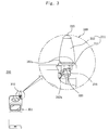
- Figure 3 is a perspective view of an antenna of a cellular phone and a partial cross sectional view of the same according to a first embodiment of the present invention;
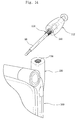
- Figure 4 is a disassembled perspective view of an antenna for a cellular phone according to a first embodiment of the present invention;
- Figure 5 is a disassembled perspective view of an antenna holder and an antenna according to a first embodiment of the present invention;
- Figure 6 is a disassembled perspective view of an antenna holder and an antenna according to a second embodiment of the present invention;
- Figure 7 is a partial cross sectional view illustrating an antenna engaging part according to a third embodiment of the present invention;
- Figure 8 is a disassembled perspective view of an antenna connector and an antenna holder according to a third embodiment of the present invention;
- Figure 9 is a partial cross sectional view illustrating an antenna engaging part according to a fourth embodiment of the present invention;
- Figure 10 is a partial enlarged view illustrating an antenna connector engaging part according to a fourth embodiment of the present invention;
- Figure 11 is a disassembled perspective view illustrating an antenna connector and an antenna holder according to a fifth embodiment of the present invention;
- Figure 12 is a partial cross sectional view illustrating an antenna engaging part according to a fifth embodiment of the present invention;
- Figure 13 is a partial enlarged view illustrating an antenna engaging part according to a fifth embodiment of the present invention; and
- Figure 14 is a perspective view illustrating the state of use of an antenna according to a fifth embodiment of the present invention.
-
- As shown in Figure 3, the
antenna 310 for a cellular phone according to a first embodiment of the present invention is installed at a certain portion of abody 301 of acellular phone 300 wherein arod antenna 315 is extendable in an upward direction of thebody 301. - The
antenna 310 includes anantenna holder 316 installed in thecellular phone body 301, anantenna housing 311 engaged to theantenna holder 316, and arod antenna 315 passing through theantenna housing 311. - As shown in Figure 4, the
antenna holder 316 is formed in a metallic hollow cylindrical shape and includes aguide groove part 320 in a wall surface and is engaged to alower frame 301a of thebody 301 and is connected with a transmission and receiving circuit (not shown) of thebody 301 for thereby performing a signal transmitting and receiving operation. - The
antenna housing 311 includes anantenna support part 312 having a rectangular cross section, and anantenna connector 313 integrally formed in thesupport part 312. Theantenna part 312 is formed of an electrically insulated material and is integrally formed in themetallic antenna connector 313 by an injection method. Theantenna support part 312 may have a rectangular cross section and may have a certain cross section shape such as a diamond shape, an elliptical shape etc. in consideration with the entire design of the cellular phone. - The
antenna housing 311 engaged with thesupport part 312 and theantenna connector 313 has a through hole (not shown) in a vertical direction, and arod antenna 315 passes through the through hole based on a sliding movement method. Anelastic protrusion part 312a contacting with thebody 301 is formed in a lower side of thesupport part 312, so that theantenna housing 311 is stably fixed with respect to thebody 301. - As shown in Figure 5, a
protrusion part 313a is formed in an outer side of theantenna connector 313 and is engaged with aguide groove part 320 of theantenna holder 316. Theprotrusion part 313a is moved through theguide groove part 320 and is fixed as theantenna housing 311 is rotated, so that theantenna housing 311 is stably fixed. - The
rod antenna 315 vertical passes through theantenna housing 311 and is installed in such a manner that it is extendable and contracted. When it is extended in the upward direction, the contacting part (not shown) of the lower end of therod antenna 315 contacts with theantenna connector 313, so that an electrical connection with the transmission and receiving circuit (not shown) of the body is implemented through theantenna holder 316 for thereby performing a signal transmission and receiving operation. - The
guide groove part 320 is formed of a plurality of grooves formed in the wall surface of theantenna holder 316. Namely, theguide groove part 320 includes anentry groove 321 formed in an outer portion of the upper hole of theantenna hole 316 so that theprotrusion part 313a is inserted, an entrystraight line groove 322 horizontally extended from theentry groove 321, aslant guiding groove 323 extended in the lower direction from the entrystraight line groove 322 at a certain inclination angle, a fixedstraight line groove 324 horizontally extended from theslant guiding groove 323, and a fixedgroove 325 formed in the end portion of the fixedstraight line groove 324. - The operation that the
protrusion part 313a is moved along theguide groove part 320, and theantenna housing 311 is fixed to thebody 301 will be described. - The
entry groove 321 operates as a path that theprotrusion part 313a is inserted. The entrystraight line groove 322 guides theprotrusion part 313a to move in the direction of theslant guiding groove 323 as theantenna housing 311 is rotated. - When the
protrusion part 313a is moved into theslant guiding groove 323, theelastic protrusion part 312a of the lower side of theantenna support part 312 contacts with the upper side of thebody 301, so that the gap between theantenna housing 311 and thebody 301 is decreased. At this time, theantenna holder 316 is pulled in the direction of theantenna housing 311 based on the construction of theslant guiding groove 323 in which a slant is formed in the axial direction of theantenna holder 316. - When the
antenna housing 311 is rotated more, theprotrusion part 313a is slid into the fixedstraight line groove 324, so that theantenna housing 311 is fixed to thebody 301, and theprotrusion part 313a is inserted into the fixinggroove 325. In the above state, it is inserted into a deeper portion in the direction of theantenna holder 316 as compared to when theprotrusion part 313a is positioned in theentry groove 321 based on the construction of theslant guiding groove 323. Theantenna holder 316 and theantenna housing 311 strongly pull each other based on the operation of theelastic protrusion part 312a. Therefore, since theprotrusion part 313 maintains a stably inserted state into the fixinggroove 325, theantenna housing 311 is stably fixed in thebody 301. - When the
antenna 310 is installed in thebody 301 of thecellular phone 300 in the above described manner, since the position of the installation is determined based on an operation between theguide groove part 320 and theprotrusion part 313a, theantenna 310 is installed in the body always in the same construction irrespective of the construction of theantenna housing 311. - In the thusly constituted antenna, when the
rod antenna 315 is damaged by an external impact, the fixing work for exchanging the antenna is performed by an easier method. - When rotating the
antenna housing 311 for exchanging theantenna 310, theprotrusion part 313a is escaped from the fixinggroove 325 and the fixedstraight line groove 324, and theantenna housing 311 and thebody 301 are disengaged. When theantenna housing 311 is more rotated, it is possible to fully separate theantenna 310 from thebody 301. - Therefore, it is possible to assemble and disassemble the
antenna 310 based on the above described easier procedure, and the user can easily repair without paying additional charges. In addition, it is possible to avoid the second error that may occur in the transmission and receiving circuit and various connection apparatuses in the cellular phone during the complicated repairing procedures. - In the first embodiment of the present invention, since only one protrusion part and one guide groove part are provided, so that the
antenna housing 311 is rotated at about 180° with respect to thebody 301 for thereby implementing an engaging operation. - As shown in Figure 6, in the second embodiment of the present invention, two
guide groove parts 420 are symmetrically provided in theantenna holder 416. Twoprotrusion parts 413a are provided in theantenna connector 413. Eachprotrusion part 413a is engaged to theguide groove part 420, so that theantenna housing 411 is fixed to the body. In the drawings,reference numeral 415 represents a rod antenna, and 412 represents an antenna support part. - The
guide groove part 420 includes anentry groove 421, an entrystraight line groove 422, aslant guide groove 423, a fixedstraight line groove 424 and a fixedgroove 425. Namely, the construction of this embodiment is similar with the construction of the second embodiment of the present invention. However, in the second embodiment of the present invention, the entire length of theguide groove part 420 is different from that of the first embodiment of the present invention. However, the entire length of theguide groove part 420 is different from the first embodiment of the present invention. Namely, twoguide groove parts 420 are symmetrically formed on theantenna holder 416. However, the operations of each groove are the same as the operation of each groove of theguide groove part 320 according to the first embodiment of the present invention. - The
protrusion part 413a is engaged to theguide groove part 420 and is inserted into the fixedgroove 425 as theantenna housing 411 is rotated at about 90°, so that theantenna housing 411 and the body are more stably fixed. - As shown in Figures 7 and 8, in the third embodiment of the present invention, the
rod antenna 98 is extendable from the upper side of thebody 100. Theantenna housing 110 having the throughhole 108 formed in the vertical direction is threaded to thebody 100 of the cellular phone in a state that theantenna housing 110 is protruded at a certain height at the upper side of thebody 100. Theantenna housing 110 includes a molded syntheticantenna support part 112, and ametallic antenna connector 114 electrically connected with the transmission and receiving circuit (not shown) of the cellular phone. - In the drawings, the cross section of the
antenna support part 112 is seen in an elliptical shape. The shape of the cross section of the same may be a diamond shape or an elliptical shape. - The
antenna connector 114 is formed in a cylindrical shape, so that therod antenna 98 passes through, and a threadedpart 116 is formed in the lower outer wall side for engaging theantenna housing 110 to thebody 100 of the cellular phone. In the interior of theantenna connector 114, there is provided an inwardly supported elastic member (not shown) for stably supporting therod antenna 98 when it is extended, and for maintaining a stable electrical connection with the lower side of therod antenna 98. On the contrary, an elastic member(not shown) may be outwardly supported in the lower side of therod antenna 98 instead the elastic member is installed in the interior of theantenna connector 114. - An
antenna engaging part 120 is formed in one upper side of thebody 100 of the cellular phone, and a hollow mountinggroove 122 is formed in the interior of theantenna engaging part 120. A threaded portion is formed in the interior of the engaginggroove 122, and anantenna holder 130 having an engaging threadedportion 124 formed in an outer portion is engaged. At this time, an insert injection may be formed together with theantenna holder 130 when molding thebody 100 of the cellular phone instead the engaging threadedportion 124 is formed in an outer wall of theantenna holder 130. - The
antenna holder 130 is formed in a hollow cylindrical shape and has a threadedgroove 132 corresponding to the threadedportion 116 in the inner wall. A pair ofprotrusion steps 134 are vertically formed at the upper side opposite to theantenna connector 114 in the portion in which the slanted surfaces stop, by cutting the shoulder portions at a certain slanted angle. - As shown in Figures 9 and 10, in the fourth embodiment of the present invention, a protrusion step 134' may be formed in the inner wall of the mounting
groove 122 instead theprotrusion step 134 is formed in theantenna connector 114. At this time, the protrusion step 134' is integrally formed when injecting the body of the cellular phone using synthetic resin like plastic. - In addition, a
stopper 140 is formed in the outer wall of thecircular antenna connector 114 for limiting the rotation of theantenna connector 114 in such a manner that it is engaged with theprotrusion step 134. Therefore, thestopper 140 formed in the outer wall of theantenna connector 114 is engaged with theprotrusion step 134 formed in the upper surface of theantenna holder 130, or thestopper 140 is engaged with the protrusion step 134' formed in the inner wall of the mountinggroove 122, so that theantenna connector 114 does not rotate. Therefore, the assembling direction of theantenna housing 110 is determined. - The protrusion steps 134, 134' are adapted to limit the rotation of the
antenna connector 114 and perform a function for determining the assembling direction of theantenna housing 110. The heights and thickness of the protrusion steps 134, 134' are preferably small within a range of 0.2mm to 1mm. - Two
engaging shoulder portions 150 are formed in the upper side of theantenna connector 114 in the same as thestopper 140 or in a similar shape of thestopper 140. The engagingshoulder portions 150 perform the function of preventing the insert-moldedantenna connector 114 from being idle-rotated with respect to the synthetic resinantenna support part 112. - The assembling procedures of the antenna according to the third and fourth embodiments of the present invention will be described.
- The assembling procedure according to the third embodiment of the present invention will be first described. The
antenna holder 130 is engaged to the mountinggroove 122 formed in the support member and is installed in such a manner that an extending line connecting theprotrusion step 134 is matched with the upper surface of thebody 100 of the cellular phone. Therod antenna 98 is inserted into the throughhole 108, and an elastic member (not shown) is installed in the lower side of the rod antenna. The threaded portion of theantenna connector 114 is inserted into the upper side of theantenna holder 130 and is rotated in the clockwise direction, so that theantenna housing 110 is engaged to thebody 100 of the cellular phone. At this time, it is rotated in the clockwise direction until thestopper 140 formed in an outer wall of theantenna connector 114 is caught by theprotrusion step 134. - The assembling procedure of the fourth embodiment of the present invention will be described. When the
antenna holder 130 is engaged to the mountinggroove 122 formed in the interior of theantenna engaging part 120, the engaging threadedportion 124 is formed in an outer wall of theantenna holder 130 for thereby engaging theantenna holder 130 to the mountinggroove 122. An insert molding may be performed when injecting and molding thebody 100 of the cellular phone. In the present invention, since the protrusion step 134' is formed in the inner wall of the mountinggroove 122 for determining the assembling direction of theantenna connector 114, it is preferred that it is integrally molded when molding thebody 100 of the cellular phone rather than the thread engagement achieved by forming the engagingscrew 124. - In addition, in the protrusion step 134', the extension line connecting the protrusion step 134' is horizontally formed and matched with the upper surface of the
body 100. Therod antenna 98 is inserted into the throughhole 108, and the elastic member (not shown) is installed at the end of therod antenna 98. The threadedportion 116 of theantenna connector 114 is inserted into the upper side of theantenna holder 130 and is rotated in the clockwise direction, so that theantenna housing 110 is engaged to thebody 100. At this time, it is rotated in the clockwise direction until thestopper 140 formed in the outer wall of theantenna connector 114 is caught by the protrusion step 134'. The shape of the insert injectedantenna support part 112 has a good look balance with thebody 100 of the cellular phone. - As shown in Figures 11, 12, 13 and 14 of the fifth embodiment of the present invention, the constructions of the
protrusion step 135 formed in theantenna holder 130 and thestopper 141 formed in theantenna connector 114 are different from that of the third and fourth embodiments of the present invention. - Namely, the
antenna engaging part 120 is formed in the upper side of thebody 100 of the cellular phone, and a hollow mountinggroove 122 is formed in the interior of theantenna engaging part 120 so that theantenna holder 130 is engaged thereinto. Arotation limit surface 126 formed of a straight surface is formed in the outer side of theantenna holder 130. Here, the inner wall of the mountinggroove 122 is formed in a shape for accommodating therotation limit surface 126 and has a function of limiting the rotation of theantenna holder 130. Theantenna holder 130 is preferably inserted into the mountinggroove 122 by a tight insertion method. - In addition, the
protrusion step 135 formed in the upper side of theantenna holder 130 has a certain construction changed from the third and fourth embodiments of the present invention. In the third and fourth embodiments of the present invention, the slanted surfaces forming the protrusion steps 134, 134' are formed along the upper outer surfaces of theantenna holder 130 in a longitudinal direction, and the ends of the slanted surfaces extended from the opposite protrusion steps 134, 134' meet each other. - In the fifth embodiment of the present invention, the construction that the
protrusion step 135 is vertically formed in the portion in which the slantedsurface 135a formed in the upper side of theantenna holder 130 is downwardly slanted is similar with the constructions of the third and fourth embodiments of the present invention. However, in the fifth embodiment of the present invention, the slantedsurface 135a is formed shorter as compared to the third and fourth embodiments in which the slantedsurface 135a is formed longer, so that the end, in which the slantedsurface 135a extended in the opposite direction of theprotrusion step 135 stops, contacts with the upper surfaces of theantenna holder 130. Therefore, the ends of the slantedsurface 135a extended from the opposite protrusion steps 135 do not meet each other. - The
protrusion step 135 formed in the above described manner is adapted to guide the movement of the antenna connector so that theantenna connector 114 is smoothly engaged with theantenna holder 130. - The
antenna connector 114 is formed in a cylindrical shape, so that therod antenna 98 passes through. A threadedpart 116 is formed in the lower portion of the outer wall. Therefore, it is engaged to the threadedgroove 132 of the inner side of theantenna holder 130. Anengaging shoulder part 151 is formed in the upper side of theantenna connector 114. Theantenna support part 112 and theantenna connector 114 are integrally formed by the insertion injection method and prevents theantenna connection 114 from being idle-rotated in the interior of theantenna support part 112. - A
stopper 141 is formed in an outer wall of theantenna connector 114 for limiting the rotation of theantenna connector 114 based on the engagement with theprotrusion step 135. Thestopper 141 is threaded with theprotrusion step 135, so that theantenna connector 114 is not rotated for thereby determining the assembling direction of theantenna housing 110. - In the above described construction, when the
antenna holder 130 is engaged to theantenna engaging part 120, therotation limit surface 126 is tightly inserted into the mountinggroove 122 of theantenna engaging part 120, so that theantenna holder 130 is preciously engaged, whereby it is possible to achieve an easier assembling operation. In addition, when theantenna connector 114 is ' engaged to theantenna holder 130 preciously engaged at the portion of theantenna engaging part 120, the shorter slanted surface of theprotrusion step 135 guides the rotation of theantenna connector 114, so that theantenna connector 114 is smoothly and stably engaged with theantenna holder 130. - As described above, in the case that the cross section of the antenna housing is not an elliptical shape, a rectangular shape or a circular shape, the antenna is installed using the thread method. In this case, the antenna housing does not have a good look balance with the body of the cellular phone. Therefore, in the present invention, when the antenna is engaged to the body of the cellular phone, the antenna may be installed always in the same type irrespective of the outer look of the antenna. The antenna is stably fixed to the body of the cellular phone. The disassembling and assembling are easy. An exchanging work is convenient.
- Namely, in the present invention, the protrusion part is formed in the antenna connector adapted to support the rod antenna. The protrusion part is inserted into the guide groove part of the antenna holder installed in the body of the cellular phone. In the present invention, it is possible to engage or disengage the antenna to/from the body of the cellular phone by rotating the antenna housing. A stopper is formed in an outer wall of the antenna housing, and a protrusion step is formed in the antenna holder or the mounting groove of the body of the cellular phone engaged with the antenna housing. Therefore, the antenna housing is rotated in the clockwise direction until the stopper is caught by the protrusion step and is stopped, so that the antenna is assembled based on the tight insertion method.
- As the present invention may be embodied in several forms without departing from the spirit or essential characteristics thereof, it should also be understood that the above-described examples are not limited by any of the details of the foregoing description, unless otherwise specified, but rather should be construed broadly within its spirit and scope as defined in the appended claims, and therefore all changes and modifications that fall within the meets and bounds of the claims, or equivalences of such meets and bounds are therefore intended to be embraced by the appended claims.
Claims (7)
- An antenna for a cellular phone, comprising:an antenna holder having a guide groove part and engaged in a body of a cellular phone;an antenna housing that is formed of an antenna connector having a protrusion part engaged to the guide groove part and fixedly inserted into the antenna holder, and an antenna support part integrally formed in the antenna connector; anda rod antenna that passes through the antenna connector and the antenna support part, respectively, in such a manner that the rod antenna is extendable from the body of the cellular phone.
- The antenna of claim 1, wherein said antenna holder includes a guide groove part formed of:an entry groove formed in a hollow cylindrical shape in such a manner that the protrusion is inserted into one side of an upper hole;an entry straight line groove horizontally extended from the entry groove;a slant guiding groove downwardly extended from the entry straight line groove; anda fixed straight line groove horizontally extended from the slant guiding groove.
- The antenna of claim 2, wherein two guide groove parts are formed in the antenna holder, and two protrusion parts engaged with the guide groove part are formed in the antenna connector.
- The antenna of one among claims 1 through 3, wherein an elastic protrusion is formed in a lower side of the antenna support part of the antenna housing, and the elastic protrusion part contacts with an outer side of the body of the cellular phone, so that the antenna housing is stably fixed to the body of the cellular phone.
- The antenna of claim 2, wherein a fixed groove is formed in the fixed straight line groove of the guide groove part of the antenna holder wherein the protrusion part of the antenna connector is fixedly inserted into one of the fixed groove.
- In an antenna for a cellular phone that includes an antenna housing formed of a metallic antenna connector electrically connected with a transmission and receiving circuit in the interior of a body of a cellular phone and having a vertical through hole in the interior of the body so that a rod antenna is upwardly expendable, and an antenna support part that is formed of a synthetic resin or rubber material and integrally formed in an outer side of the antenna connector by an insert injection method so that a cross sectional shape is line-symmetrical line an elliptical shape or a rectangular shape, an antenna engaging part formed in one side of the upper side of the body so that the antenna housing is engaged to the body of the cellular phone, and a metallic antenna holder installed in a hollow mounting groove formed in the antenna engaging part, an improved antenna for a cellular phone, comprising:a protrusion step vertically formed in the upper side of the antenna holder at both sides of the same in such a manner that a downwardly slanted groove is formed from one side to the other side or from the other side to one side, wherein the antenna holder is installed in the mounting groove in such a manner that an extension line connecting both protrusion steps is horizontal with respect to the upper surface of the body of the cellular phone; anda stopper provided at both sides of the outer wall of the antenna connector and engaged with the protrusion step, wherein both ends of the antenna support part are horizontal with respect to the upper surface of the body of the cellular phone and are matched with the upper surface of the antenna engaging part.
- The antenna of claim 6, wherein the height of the protrusion step is within a range of 0.2mm through 1mm.
Applications Claiming Priority (4)
| Application Number | Priority Date | Filing Date | Title |
|---|---|---|---|
| KR1020030031332A KR100608257B1 (en) | 2003-05-16 | 2003-05-16 | Contracting structure of hand phone antenna |
| KR2003031332 | 2003-05-16 | ||
| KR2003085275 | 2003-11-27 | ||
| KR1020030085275A KR100549806B1 (en) | 2003-11-27 | 2003-11-27 | Antenna assembly for a cellular phone |
Publications (2)
| Publication Number | Publication Date |
|---|---|
| EP1478048A2 true EP1478048A2 (en) | 2004-11-17 |
| EP1478048A3 EP1478048A3 (en) | 2005-01-19 |
Family
ID=33032433
Family Applications (1)
| Application Number | Title | Priority Date | Filing Date |
|---|---|---|---|
| EP04010759A Withdrawn EP1478048A3 (en) | 2003-05-16 | 2004-05-06 | Antenna for cellular phone |
Country Status (6)
| Country | Link |
|---|---|
| US (1) | US20040227676A1 (en) |
| EP (1) | EP1478048A3 (en) |
| JP (1) | JP2004343704A (en) |
| CN (1) | CN1551409A (en) |
| CA (1) | CA2458735A1 (en) |
| IL (1) | IL160616A0 (en) |
Families Citing this family (40)
| Publication number | Priority date | Publication date | Assignee | Title |
|---|---|---|---|---|
| TWI234310B (en) * | 2003-09-24 | 2005-06-11 | Benq Corp | Antenna engaging mechanism in wireless communication device |
| US7190311B2 (en) * | 2004-07-06 | 2007-03-13 | Motorola, Inc. | Alignment cam for non-circular retractable antenna |
| US7486240B2 (en) * | 2004-10-12 | 2009-02-03 | Qualcomm Incorporated | Devices and methods for retaining an antenna |
| KR100710624B1 (en) * | 2005-07-27 | 2007-12-03 | 엘지전자 주식회사 | Portable phone having screw type antenna |
| CN101567481B (en) * | 2008-04-22 | 2012-09-19 | 启碁科技股份有限公司 | Antenna module |
| US8902108B2 (en) * | 2008-05-30 | 2014-12-02 | Gigaset Communications Gmbh | Housing antenna system |
| JP5651974B2 (en) * | 2010-03-26 | 2015-01-14 | 富士通株式会社 | Mobile terminal device |
| TWI429135B (en) * | 2010-08-24 | 2014-03-01 | Gemtek Technology Co Ltd | Multi-directional pivoting antenna |
| US9247212B2 (en) | 2010-08-26 | 2016-01-26 | Blast Motion Inc. | Intelligent motion capture element |
| US9607652B2 (en) | 2010-08-26 | 2017-03-28 | Blast Motion Inc. | Multi-sensor event detection and tagging system |
| US9626554B2 (en) | 2010-08-26 | 2017-04-18 | Blast Motion Inc. | Motion capture system that combines sensors with different measurement ranges |
| US8994826B2 (en) | 2010-08-26 | 2015-03-31 | Blast Motion Inc. | Portable wireless mobile device motion capture and analysis system and method |
| US8702516B2 (en) | 2010-08-26 | 2014-04-22 | Blast Motion Inc. | Motion event recognition system and method |
| US9401178B2 (en) | 2010-08-26 | 2016-07-26 | Blast Motion Inc. | Event analysis system |
| US8944928B2 (en) | 2010-08-26 | 2015-02-03 | Blast Motion Inc. | Virtual reality system for viewing current and previously stored or calculated motion data |
| US8941723B2 (en) | 2010-08-26 | 2015-01-27 | Blast Motion Inc. | Portable wireless mobile device motion capture and analysis system and method |
| US8827824B2 (en) | 2010-08-26 | 2014-09-09 | Blast Motion, Inc. | Broadcasting system for broadcasting images with augmented motion data |
| US9940508B2 (en) | 2010-08-26 | 2018-04-10 | Blast Motion Inc. | Event detection, confirmation and publication system that integrates sensor data and social media |
| US9039527B2 (en) | 2010-08-26 | 2015-05-26 | Blast Motion Inc. | Broadcasting method for broadcasting images with augmented motion data |
| US9261526B2 (en) | 2010-08-26 | 2016-02-16 | Blast Motion Inc. | Fitting system for sporting equipment |
| US9406336B2 (en) | 2010-08-26 | 2016-08-02 | Blast Motion Inc. | Multi-sensor event detection system |
| US9396385B2 (en) | 2010-08-26 | 2016-07-19 | Blast Motion Inc. | Integrated sensor and video motion analysis method |
| US9646209B2 (en) | 2010-08-26 | 2017-05-09 | Blast Motion Inc. | Sensor and media event detection and tagging system |
| US8905855B2 (en) | 2010-08-26 | 2014-12-09 | Blast Motion Inc. | System and method for utilizing motion capture data |
| US9320957B2 (en) | 2010-08-26 | 2016-04-26 | Blast Motion Inc. | Wireless and visual hybrid motion capture system |
| US8903521B2 (en) | 2010-08-26 | 2014-12-02 | Blast Motion Inc. | Motion capture element |
| US9076041B2 (en) | 2010-08-26 | 2015-07-07 | Blast Motion Inc. | Motion event recognition and video synchronization system and method |
| US9604142B2 (en) | 2010-08-26 | 2017-03-28 | Blast Motion Inc. | Portable wireless mobile device motion capture data mining system and method |
| US9619891B2 (en) | 2010-08-26 | 2017-04-11 | Blast Motion Inc. | Event analysis and tagging system |
| US9235765B2 (en) | 2010-08-26 | 2016-01-12 | Blast Motion Inc. | Video and motion event integration system |
| US9418705B2 (en) | 2010-08-26 | 2016-08-16 | Blast Motion Inc. | Sensor and media event detection system |
| US8913134B2 (en) | 2012-01-17 | 2014-12-16 | Blast Motion Inc. | Initializing an inertial sensor using soft constraints and penalty functions |
| US10124230B2 (en) | 2016-07-19 | 2018-11-13 | Blast Motion Inc. | Swing analysis method using a sweet spot trajectory |
| US10974121B2 (en) | 2015-07-16 | 2021-04-13 | Blast Motion Inc. | Swing quality measurement system |
| US11565163B2 (en) | 2015-07-16 | 2023-01-31 | Blast Motion Inc. | Equipment fitting system that compares swing metrics |
| US9694267B1 (en) | 2016-07-19 | 2017-07-04 | Blast Motion Inc. | Swing analysis method using a swing plane reference frame |
| US11577142B2 (en) | 2015-07-16 | 2023-02-14 | Blast Motion Inc. | Swing analysis system that calculates a rotational profile |
| US10265602B2 (en) | 2016-03-03 | 2019-04-23 | Blast Motion Inc. | Aiming feedback system with inertial sensors |
| US10786728B2 (en) | 2017-05-23 | 2020-09-29 | Blast Motion Inc. | Motion mirroring system that incorporates virtual environment constraints |
| TWI751865B (en) * | 2020-12-29 | 2022-01-01 | 和碩聯合科技股份有限公司 | Electronic device |
Citations (6)
| Publication number | Priority date | Publication date | Assignee | Title |
|---|---|---|---|---|
| US4611213A (en) * | 1984-06-08 | 1986-09-09 | Amp Incorporated | Coaxial connector for antenna |
| FR2691841A1 (en) * | 1992-05-29 | 1993-12-03 | Peugeot | Radio aerial for car - has lower element connected to coaxial cable and click fitting internally into hole in car bodywork, with antenna support plugging into it from exterior of vehicle |
| US5859617A (en) * | 1995-06-30 | 1999-01-12 | Smk Corporation | Extendable rod antenna and helical antenna with frequency adjusting conductor |
| US5955999A (en) * | 1997-10-15 | 1999-09-21 | Motorola, Inc. | Antenna assembly for a radiotelephone |
| GB2337364A (en) * | 1998-05-15 | 1999-11-17 | Motorola Ltd | Antenna and radio unit with a ratchet coupling arrangement |
| US20010004248A1 (en) * | 1999-12-16 | 2001-06-21 | Naoyuki Takagi | Antenna device |
Family Cites Families (9)
| Publication number | Priority date | Publication date | Assignee | Title |
|---|---|---|---|---|
| US5243355A (en) * | 1991-03-04 | 1993-09-07 | Motorola, Inc. | Semiautomatic retractable antenna apparatus |
| GB2257835B (en) * | 1991-07-13 | 1995-10-11 | Technophone Ltd | Retractable antenna |
| US6078291A (en) * | 1996-09-24 | 2000-06-20 | Motorola, Inc. | Antenna assembly and method for attaching an antenna |
| JPH11298219A (en) * | 1998-04-10 | 1999-10-29 | Tokin Corp | Antenna and portable radio equipment using the antenna |
| US6414638B1 (en) * | 1998-07-27 | 2002-07-02 | Houkou Electric Corporation | Antenna for radio telephone |
| JP2000188503A (en) * | 1998-12-22 | 2000-07-04 | Yokowo Co Ltd | Antenna for portable radio unit |
| JP3537770B2 (en) * | 1999-04-06 | 2004-06-14 | 三菱電機株式会社 | Portable wireless device and method of manufacturing casing for portable wireless device |
| US6201503B1 (en) * | 1999-12-22 | 2001-03-13 | Kabushiki Kaisha Yokowo | Antenna for radio device and radio device |
| US6603433B1 (en) * | 2002-03-01 | 2003-08-05 | Auden Techno Corp. | Positioning structure of inner and outer insulation sleeve members for antenna |
-
2004
- 2004-02-24 US US10/785,801 patent/US20040227676A1/en not_active Abandoned
- 2004-02-25 CA CA002458735A patent/CA2458735A1/en not_active Abandoned
- 2004-02-26 IL IL16061604A patent/IL160616A0/en unknown
- 2004-03-03 JP JP2004059881A patent/JP2004343704A/en active Pending
- 2004-03-15 CN CNA2004100399516A patent/CN1551409A/en active Pending
- 2004-05-06 EP EP04010759A patent/EP1478048A3/en not_active Withdrawn
Patent Citations (6)
| Publication number | Priority date | Publication date | Assignee | Title |
|---|---|---|---|---|
| US4611213A (en) * | 1984-06-08 | 1986-09-09 | Amp Incorporated | Coaxial connector for antenna |
| FR2691841A1 (en) * | 1992-05-29 | 1993-12-03 | Peugeot | Radio aerial for car - has lower element connected to coaxial cable and click fitting internally into hole in car bodywork, with antenna support plugging into it from exterior of vehicle |
| US5859617A (en) * | 1995-06-30 | 1999-01-12 | Smk Corporation | Extendable rod antenna and helical antenna with frequency adjusting conductor |
| US5955999A (en) * | 1997-10-15 | 1999-09-21 | Motorola, Inc. | Antenna assembly for a radiotelephone |
| GB2337364A (en) * | 1998-05-15 | 1999-11-17 | Motorola Ltd | Antenna and radio unit with a ratchet coupling arrangement |
| US20010004248A1 (en) * | 1999-12-16 | 2001-06-21 | Naoyuki Takagi | Antenna device |
Also Published As
| Publication number | Publication date |
|---|---|
| CN1551409A (en) | 2004-12-01 |
| JP2004343704A (en) | 2004-12-02 |
| EP1478048A3 (en) | 2005-01-19 |
| IL160616A0 (en) | 2004-07-25 |
| US20040227676A1 (en) | 2004-11-18 |
| CA2458735A1 (en) | 2004-11-16 |
Similar Documents
| Publication | Publication Date | Title |
|---|---|---|
| EP1478048A2 (en) | Antenna for cellular phone | |
| US8355760B2 (en) | Portable terminal having reinforcement member | |
| EP3355157A1 (en) | Housing assembly and electronic device | |
| EP2020806A2 (en) | Combined mechanism for sliding movement and rotating movement and a portable electronic appliance employing the same | |
| KR20110015908A (en) | Antenna pattern frame, method and mould for manufacturing the same, electronic device having antenna pattern frame embeded therein and method for manufacturing the same | |
| CN201349370Y (en) | Dust-proof structure and electronic equipment with same | |
| CN102859976B (en) | Portable apparatus | |
| US8241782B2 (en) | Battery cover and portable electronic device using the same | |
| US20100035668A1 (en) | Slide hinge module for mobile phone | |
| US20110170245A1 (en) | Tilting portable electronic device | |
| US20110017000A1 (en) | Slide apparatus for mobile communication terminal | |
| US20040229666A1 (en) | Case for mobile communication terminal | |
| US20100027203A1 (en) | Latch | |
| CN101752537A (en) | Battery cover structure | |
| KR101097041B1 (en) | Apparatus of antenna hinge | |
| US8422214B2 (en) | Mobile electronic apparatus | |
| KR101059221B1 (en) | Slide Hinge Modules for Mobile Phones | |
| KR20050056705A (en) | A slide type mobile communication terminal | |
| KR100597163B1 (en) | Antenna assembly for a cellular phone | |
| US8517210B2 (en) | Screw protection cover and shell assembly using the same | |
| KR100549806B1 (en) | Antenna assembly for a cellular phone | |
| KR200356535Y1 (en) | Antenna assembly for a cellular phone | |
| KR200341723Y1 (en) | Antenna assembly for a cellular phone | |
| CN217414598U (en) | Structure capable of preventing single side abrasion | |
| JP6054903B2 (en) | Electronic device assembly method and electronic device |
Legal Events
| Date | Code | Title | Description |
|---|---|---|---|
| PUAI | Public reference made under article 153(3) epc to a published international application that has entered the european phase |
Free format text: ORIGINAL CODE: 0009012 |
|
| 17P | Request for examination filed |
Effective date: 20040506 |
|
| AK | Designated contracting states |
Kind code of ref document: A2 Designated state(s): AT BE BG CH CY CZ DE DK EE ES FI FR GB GR HU IE IT LI LU MC NL PL PT RO SE SI SK TR |
|
| AX | Request for extension of the european patent |
Extension state: AL HR LT LV MK |
|
| PUAL | Search report despatched |
Free format text: ORIGINAL CODE: 0009013 |
|
| AK | Designated contracting states |
Kind code of ref document: A3 Designated state(s): AT BE BG CH CY CZ DE DK EE ES FI FR GB GR HU IE IT LI LU MC NL PL PT RO SE SI SK TR |
|
| AX | Request for extension of the european patent |
Extension state: AL HR LT LV MK |
|
| AKX | Designation fees paid |
Designated state(s): AT BE BG CH CY CZ DE DK EE ES FI FR GB GR HU IE IT LI LU MC NL PL PT RO SE SI SK TR |
|
| STAA | Information on the status of an ep patent application or granted ep patent |
Free format text: STATUS: THE APPLICATION HAS BEEN WITHDRAWN |
|
| 18W | Application withdrawn |
Effective date: 20051007 |