EP1477934A2 - Image processing apparatus - Google Patents
Image processing apparatus Download PDFInfo
- Publication number
- EP1477934A2 EP1477934A2 EP04252601A EP04252601A EP1477934A2 EP 1477934 A2 EP1477934 A2 EP 1477934A2 EP 04252601 A EP04252601 A EP 04252601A EP 04252601 A EP04252601 A EP 04252601A EP 1477934 A2 EP1477934 A2 EP 1477934A2
- Authority
- EP
- European Patent Office
- Prior art keywords
- teaching model
- attitude
- captured
- images
- image
- Prior art date
- Legal status (The legal status is an assumption and is not a legal conclusion. Google has not performed a legal analysis and makes no representation as to the accuracy of the status listed.)
- Withdrawn
Links
Images



Classifications
-
- G—PHYSICS
- G05—CONTROLLING; REGULATING
- G05D—SYSTEMS FOR CONTROLLING OR REGULATING NON-ELECTRIC VARIABLES
- G05D1/00—Control of position, course, altitude or attitude of land, water, air or space vehicles, e.g. using automatic pilots
- G05D1/40—Control within particular dimensions
- G05D1/49—Control of attitude, i.e. control of roll, pitch or yaw
-
- G—PHYSICS
- G05—CONTROLLING; REGULATING
- G05D—SYSTEMS FOR CONTROLLING OR REGULATING NON-ELECTRIC VARIABLES
- G05D1/00—Control of position, course, altitude or attitude of land, water, air or space vehicles, e.g. using automatic pilots
- G05D1/20—Control system inputs
- G05D1/24—Arrangements for determining position or orientation
- G05D1/243—Means capturing signals occurring naturally from the environment, e.g. ambient optical, acoustic, gravitational or magnetic signals
-
- G—PHYSICS
- G06—COMPUTING OR CALCULATING; COUNTING
- G06T—IMAGE DATA PROCESSING OR GENERATION, IN GENERAL
- G06T7/00—Image analysis
- G06T7/70—Determining position or orientation of objects or cameras
- G06T7/73—Determining position or orientation of objects or cameras using feature-based methods
- G06T7/75—Determining position or orientation of objects or cameras using feature-based methods involving models
-
- G—PHYSICS
- G06—COMPUTING OR CALCULATING; COUNTING
- G06T—IMAGE DATA PROCESSING OR GENERATION, IN GENERAL
- G06T2207/00—Indexing scheme for image analysis or image enhancement
- G06T2207/30—Subject of image; Context of image processing
- G06T2207/30108—Industrial image inspection
- G06T2207/30164—Workpiece; Machine component
Definitions
- the present invention relates to an image processing apparatus for detecting the position and attitude of an object.
- the present invention relates to an image processing apparatus for recognizing and detecting the attitude of randomly piled obj ects having an identical form, the positions and attitudes of which vary three-dimensionally.
- a plurality of images of an object captured from various directions are stored in advance as teaching model images, whereupon the stored teaching model images are compared with an input image captured upon detection of the position and attitude of the obj ect in order to select the teaching model which most closely resembles the captured image.
- the position and attitude of the object are then determined on the basis of the selected teaching model.
- a visual sensor is caused to move to the position and attitude at which the object is to be recognized, and thus the position and attitude of the object are recognized accurately using this visual sensor.
- an image cutting recognition apparatus is constituted by an object learning apparatus and an object recognition apparatus.
- the region of an object is extracted from image data obtained by capturing images of the object from various directions using first image input means, and image processing data are obtained bynormalizing the image data value of the extracted object region.
- image processing data are obtained bynormalizing the image data value of the extracted object region.
- a learned image data set is obtained.
- the form of amanifold is then calculated from the learned image data set and characteristic vectors determined from the learned image data set.
- the region of the object is extracted from image data obtained using second image input means, whereupon a distance value is calculated from data obtained by normalizing the image data value of the extracted region, the aforementioned characteristic vectors, and the aforementioned manifold form, and thus the position, direction, and magnitude of the object are outputted.
- the technology described in the Japanese Unexamined Patent Application 2000-288974 is applied in particular to an operation to pick up randomly piled objects of the same shape one by one.
- a plurality of teaching model images is determined by capturing images of the objects from various directions.
- the teaching model images are then compared to input images obtained by capturing images of several of the piled objects, whereupon the teaching model image which most closely resembles the captured image is selected.
- the selected teaching model is then used to determine the three-dimensional position and attitude of the object.
- a visual sensor is moved to the position and attitude at which the object is to be recognized, and the position and attitude of the object are recognized accurately by the visual sensor.
- the position and attitude of the object can be recognized with greater accuracy as the number of teaching models is increased.
- An image processing apparatus recognizes the attitude of an object by means of a comparison between an input image of the object captured by imaging means and a teaching model of the object.
- the image processing apparatus comprises a first teaching model constituted by direction data obtained when images of the object are captured from a plurality of directions so as to cover discretely the entire range of views that the object is able to take, and captured images corresponding to the direction data; a second teaching model constituted by direction data obtained when images of the object are captured from a plurality of directions, covering only a partial range of the views that the object is able to take at a narrower directional variation pitch than that of the first teaching model, and captured images corresponding to the direction data; first comparing means for comparing a first input image of the object captured by the imaging means with each image of the first teaching model; relative position and attitude modifying means of the imaging means for modifying the position and attitude of the object relative to the imaging means on the basis of the comparison result of the first comparing means so as to enter the range of views of the second teaching model;
- the relative position and attitude modifying means may be constituted as a robot.
- the comparison by the first and second comparison means may be performed by matching.
- the comparison by the first and second comparing means may also be performed by comparing intermediate images produced by orthogonal transformation of the input image and multiple view images.
- an image processing apparatus which is capable of recognizing the attitude of an object in a wide range and with high precision using a small number of teaching models is provided.
- Fig. 1 is a system diagram of a robot system to which an image processing apparatus according to an embodiment of the present invention is applied.
- a robot controller 3 and an image processing apparatus 1 are connected via a communication interface.
- a camera 4 imaging means for capturing images of an object (workpiece 6) is mounted on the arm tip of a robot main body 2, the camera 4 and image processing apparatus 1 being connected by a signal wire so that images captured by the camera 4 are inputted into the image processing apparatus 1.
- the robot controller 3 and image processing apparatus 1 implement the entire system operation while transmitting and receiving information to and from each other synchronously.
- the robot controller 3 transmits the current position of the robot, which is learned by the robot controller 3, to the image processing apparatus 1, and outputs an imaging command to the image processing apparatus 1.
- the image processing apparatus 1 receives the imaging command from the robot controller 3 and captures an image of the workpiece 6 using the camera 4. Further, the image processing apparatus 1 transmits a target operating position of the robot, determined by the image processing apparatus 1, to the robot controller 3.
- the robot controller 3 controls driving sources such as servomotors which drive the various functional portions of the robot main body 2 in order to position the robot main body 2 in the target operating position.
- the numeral 5 in Fig. 1 indicates a hand attached to the arm tip of the robot.
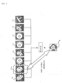
- Fig. 2 is a view illustrating a method of recognizing the position and attitude of the workpiece 6 by comparing a plurality of teaching model images obtained by capturing images of the workpiece 6 from a plurality of different directions with an inputted image captured by the camera 4.
- images of the workpiece subject to position and attitude recognition are captured from various directions. Each image is then related to data regarding the imaging direction at the time of image capture and stored in the image processing apparatus 1 as a first teaching model.
- images of the workpiece are captured from eight different directions, and the resulting images 10... are stored as the teaching model images.
- a captured and inputted image 9 of the workpiece 6 is compared respectively with the eight teaching model images, whereupon the teaching model which most closely resembles the input image 9 is selected.
- Conventional methods employed in this comparison include matching according to the correlation between the brightness of the images and a method in which orthogonal transformation is performed by means of Fourier transform, discrete cosine transform or similar and the degree of resemblance is calculated as a distance within a subspace by comparing the orthogonally transformed intermediate images with each other.
- orthogonal transformation By performing this orthogonal transformation, the data dimension can be reduced in comparison with a case in which a direct correlation calculation is performed on the images, and as a result, the calculation load involved in the comparison of similar images can be reduced.
- Fig. 2 shows as example in which as a result of the comparison, a teaching model 10a is selected as the teaching model most closely resembling the input image 9 from among the eight teaching models 10....
- Fig. 3 is an illustrative view of a method of obtaining the various images of the first teaching model in order to perform a first stage of the comparison.
- the various teaching model images used to perform the first stage of the comparison are obtained by capturing images of a workpiece from different directions in order to cover the entire region of variation in the view of the workpiece to be recognized, resulting from variation in the attitude of the workpiece.
- images of the workpiece 6 are captured while varying the sight line direction of the camera 4 that is mounted on the arm tip of the robot main body 2, or a plurality of images are captured by fixing the camera and varying the attitude of the workpiece 6 to alter the attitude of the workpiece 6 relative to the camera 4, thus dividing the entire region of the attitudes that can possibly be taken by the workpiece 6.
- images of the workpiece 6 are captured while varying the position of the camera 4 or the attitude of the workpiece 6 in various direction at a directional angle pitch of between 30 and 45 degrees from the reference coordinates at which the workpiece 6 is placed, whereupon the captured images are stored in storage means within the image processing apparatus 1 as the various images of the first teaching model.
- the imaging directions of the camera 4 relative to the imaged workpiece 6 are related to the captured images and stored in the storage means within the image processing apparatus 1 as teaching data of the first teaching model.
- second teaching model images are obtained for a second stage of the comparison, and these images are stored in storage means within the image processing apparatus 1. These second teaching model images are obtained by varying the imaging direction of the camera 4 relative to the workpiece 6 at a narrower pitch than the variation pitch of the imaging direction in the first teaching model within only a partial range of the viewing region of the workpiece 6.
- images are captured by varying the imaging direction every 10 degrees only within a range of ⁇ 30 degrees formed by the optical axis of the imaging camera with respect to the vertical direction (Z axis direction) , whereupon the captured images 20 are related to the corresponding imaging direction data and they are stored in storage means within the image processing apparatus 1 as the second teaching model.
- Fig. 5 is a flowchart of processing for determining the position and attitude of a workpiece using the robot system of this embodiment.
- the robot controller 3 drives various axles of the robot main body 2 to move the camera 4 mounted on the arm tip of the robot into an imaging position in relation to a pile of workpieces subject to three-dimensional position and attitude recognition (step 100). Then, the three-dimensional position of the camera is transmitted to the image processing apparatus together with an imaging command (step 101).
- a processor of the image processing apparatus 1 stores the three-dimensional position of the camera 4 transmitted from the robot controller 3, and upon reception of the imaging command, uses the camera 4 to capture an image of the workpiece 6, whereupon this image (first input image) is inputted (step 102).
- a comparison of the input image and the various teaching model images of the first teaching model stored in the storage means is then performed by means of matching or the like. Since details of the processing involved in this comparison are disclosed in detail in the aforementioned Japanese Unexamined Patent Application 2000-288974 and are known universally, a detailed description thereof has been omitted.
- the attitude of the camera 4 relative to the workpiece 6 is determined from the imaging direction of the camera in relation to the workpiece 6, which is stored in the selected teaching model (step 105).
- a target moving position of the camera 4 is then determined from the three-dimensional position of the camera 4 (the current position of the robot) stored in the step 101 and the attitude of the camera relative to the workpiece determined in the step 105, whereupon this target moving position is outputted to the robot controller 3 (step 106).
- the target moving position of the camera 4 is a target position to which the camera 4 is moved relative to the workpiece in order to cause the camera 4 to input an image to be used in the second stage of the comparison with the second teaching model.
- the robot controller 3 drives the various axles of the robot main body to move the camera 4 mounted on the arm tip of the robot to the received target moving position (step 107).
- An imaging command is then outputted to the image processing apparatus 1 (step 108).
- the image processing apparatus 1 receives the imaging command and captures an image (second input image) of the workpiece 6 using the camera 4 (step 109).
- the obtained image is compared with each of the second teaching model images in a similar fashion to the comparison with the first teaching model images, and a similar teaching model is selected.
- a teaching model with a degree of similarity at or above a predetermined level cannot be detected within the second teaching model, the processing ends.
- the teaching model most closely resembling the image is selected (steps 110, 111).
- the attitude of the camera 4 relative to the workpiece 6 is determined from the imaging direction of the camera 4 in relation to the workpiece that is stored in the selected teaching model (step 112).
- the position and attitude of the workpiece 6 are determined from the determined relative attitude of the camera 4 and the current three-dimensional position of the camera 4 (the target moving position determined in the step 106) (step 113).
- the attitude of the workpiece 6 is determined from a rough division thereof on the basis of the first teaching model, whereupon the camera 4 is moved in accordance with the determined workpiece attitude and position to a predetermined position and attitude within a predetermined range of the view of the workpiece 6 for capturing an image to be used in the comparison with the second teaching model.
- An image is then inputted and the inputted image is compared with the various images of the second teaching model, in which the attitude of the workpiece 6 is stored at a narrow pitch, and thus the position and attitude of the workpiece 6 is determined.
- the position and attitude of the workpiece 6 can be determined with a high degree of precision from a small number of teaching models.
- handling processing such as grasping the recognized workpiece 6 by the hand 5 and picking the workpiece 6 up is performed.
- the attitude of a workpiece can be recognized with a high degree of precision from a small number of teaching models.
Landscapes
- Engineering & Computer Science (AREA)
- Physics & Mathematics (AREA)
- General Physics & Mathematics (AREA)
- Computer Vision & Pattern Recognition (AREA)
- Theoretical Computer Science (AREA)
- Radar, Positioning & Navigation (AREA)
- Aviation & Aerospace Engineering (AREA)
- Remote Sensing (AREA)
- Automation & Control Theory (AREA)
- Manipulator (AREA)
- Image Analysis (AREA)
- Image Processing (AREA)
- Length Measuring Devices By Optical Means (AREA)
- Numerical Control (AREA)
Abstract
Description
Claims (4)
- An image processing apparatus for recognizing at least the attitude of an object by comparing an input image of said object captured by imaging means with a teaching model of said object, comprising:a first teaching model constituted by direction data obtained when images of said object are captured from a plurality of directions so as to cover discretely the entire range of views that said object is able to take, and captured images corresponding to said direction data;a second teaching model constituted by direction data obtained when images of said object are captured from a plurality of directions, covering only a partial range of the views that said object is able to take at a narrower directional variation pitch than that of said first teaching model, and captured images corresponding to said direction data;first comparing means for comparing a first input image of said object captured by said imaging means with each image of said first teaching model;relative position and attitude modifying means of said imaging means for modifying the position and attitude of said object relative to said imaging means on the basis of the comparison result of said first comparing means so as to enter the range of views of said second teaching model; andsecond comparing means for comparing a second input image of said object captured by said imaging means in the modified relative position and attitude thereof, using said second teaching model.
- The image processing apparatus according to claim 1, wherein said relative position and attitude modifying means are constituted by a robot.
- The image processing apparatus according to claim 1, wherein the comparison by said first and second comparing means is performed by matching.
- The image processing apparatus according to claim 1, wherein the comparison by said first and second comparing means is performed by comparing intermediate images produced by orthogonal transformation of said input image and said multiple view images.
Applications Claiming Priority (2)
| Application Number | Priority Date | Filing Date | Title |
|---|---|---|---|
| JP2003132962A JP3834297B2 (en) | 2003-05-12 | 2003-05-12 | Image processing device |
| JP2003132962 | 2003-05-12 |
Publications (2)
| Publication Number | Publication Date |
|---|---|
| EP1477934A2 true EP1477934A2 (en) | 2004-11-17 |
| EP1477934A3 EP1477934A3 (en) | 2009-01-07 |
Family
ID=33028321
Family Applications (1)
| Application Number | Title | Priority Date | Filing Date |
|---|---|---|---|
| EP04252601A Withdrawn EP1477934A3 (en) | 2003-05-12 | 2004-05-05 | Image processing apparatus |
Country Status (6)
| Country | Link |
|---|---|
| US (1) | US7283661B2 (en) |
| EP (1) | EP1477934A3 (en) |
| JP (1) | JP3834297B2 (en) |
| KR (1) | KR100693262B1 (en) |
| CN (1) | CN100379530C (en) |
| TW (1) | TWI244427B (en) |
Cited By (1)
| Publication number | Priority date | Publication date | Assignee | Title |
|---|---|---|---|---|
| WO2007090557A3 (en) * | 2006-02-08 | 2008-03-06 | Kuka Roboter Gmbh | Method for generating an environmental image |
Families Citing this family (38)
| Publication number | Priority date | Publication date | Assignee | Title |
|---|---|---|---|---|
| US6627863B2 (en) * | 2000-12-15 | 2003-09-30 | Mitutoyo Corporation | System and methods to determine the settings of multiple light sources in a vision system |
| EP1472052A2 (en) * | 2002-01-31 | 2004-11-03 | Braintech Canada, Inc. | Method and apparatus for single camera 3d vision guided robotics |
| US20070276539A1 (en) * | 2006-05-25 | 2007-11-29 | Babak Habibi | System and method of robotically engaging an object |
| WO2008036354A1 (en) * | 2006-09-19 | 2008-03-27 | Braintech Canada, Inc. | System and method of determining object pose |
| WO2008076942A1 (en) * | 2006-12-15 | 2008-06-26 | Braintech Canada, Inc. | System and method of identifying objects |
| US7957583B2 (en) * | 2007-08-02 | 2011-06-07 | Roboticvisiontech Llc | System and method of three-dimensional pose estimation |
| KR100920931B1 (en) * | 2007-11-16 | 2009-10-12 | 전자부품연구원 | Object posture recognition method of robot using TFT camera |
| JP4835616B2 (en) | 2008-03-10 | 2011-12-14 | トヨタ自動車株式会社 | Motion teaching system and motion teaching method |
| CN101637908B (en) * | 2008-07-29 | 2010-11-03 | 上海发那科机器人有限公司 | Visual positioning method for robot transport operation |
| JP4866890B2 (en) * | 2008-10-08 | 2012-02-01 | 本田技研工業株式会社 | Work shape estimation device |
| US8559699B2 (en) * | 2008-10-10 | 2013-10-15 | Roboticvisiontech Llc | Methods and apparatus to facilitate operations in image based systems |
| JP4651704B2 (en) * | 2008-11-14 | 2011-03-16 | シャープ株式会社 | Image processing device |
| JP5542329B2 (en) * | 2008-12-26 | 2014-07-09 | 株式会社新栄電器製作所 | Phase difference detection system |
| JP2010214546A (en) * | 2009-03-17 | 2010-09-30 | Fuji Electric Holdings Co Ltd | Assembly apparatus and assembly method |
| JP5525953B2 (en) * | 2010-07-29 | 2014-06-18 | 株式会社キーエンス | Dimension measuring apparatus, dimension measuring method and program for dimension measuring apparatus |
| US8781629B2 (en) * | 2010-09-22 | 2014-07-15 | Toyota Motor Engineering & Manufacturing North America, Inc. | Human-robot interface apparatuses and methods of controlling robots |
| JP5759133B2 (en) * | 2010-09-24 | 2015-08-05 | Juki株式会社 | Shape-based matching parameter adjustment device and component mounting device |
| US8983179B1 (en) * | 2010-11-10 | 2015-03-17 | Google Inc. | System and method for performing supervised object segmentation on images |
| JP5868005B2 (en) * | 2011-02-04 | 2016-02-24 | キヤノン株式会社 | Imaging apparatus, imaging condition setting method, program |
| JP5699697B2 (en) * | 2011-03-07 | 2015-04-15 | セイコーエプソン株式会社 | Robot device, position and orientation detection device, position and orientation detection program, and position and orientation detection method |
| US9279661B2 (en) * | 2011-07-08 | 2016-03-08 | Canon Kabushiki Kaisha | Information processing apparatus and information processing method |
| JP5806606B2 (en) * | 2011-12-01 | 2015-11-10 | キヤノン株式会社 | Information processing apparatus and information processing method |
| EP2602588A1 (en) | 2011-12-06 | 2013-06-12 | Hexagon Technology Center GmbH | Position and Orientation Determination in 6-DOF |
| JP6000579B2 (en) * | 2012-03-09 | 2016-09-28 | キヤノン株式会社 | Information processing apparatus and information processing method |
| US9251394B2 (en) * | 2012-04-05 | 2016-02-02 | Ancestry.Com Operations Inc. | System and method for estimating/determining the date of a photo |
| CN103112008B (en) * | 2013-01-29 | 2015-09-02 | 上海智周自动化工程有限公司 | Two vision robots for floor cutting locate and method for carrying automatically |
| JP2014180720A (en) * | 2013-03-19 | 2014-09-29 | Yaskawa Electric Corp | Robot system and calibration method |
| JP6915326B2 (en) * | 2017-03-17 | 2021-08-04 | 富士フイルムビジネスイノベーション株式会社 | Image processing equipment, image processing systems and programs |
| CN110127523A (en) * | 2018-02-02 | 2019-08-16 | 盟立自动化股份有限公司 | Suspension transportation device and system for automatic optical identification of materials |
| JP6836561B2 (en) | 2018-09-20 | 2021-03-03 | ファナック株式会社 | Image processing device and image processing method |
| US10926416B2 (en) * | 2018-11-21 | 2021-02-23 | Ford Global Technologies, Llc | Robotic manipulation using an independently actuated vision system, an adversarial control scheme, and a multi-tasking deep learning architecture |
| JP7047726B2 (en) * | 2018-11-27 | 2022-04-05 | トヨタ自動車株式会社 | Gripping robot and control program for gripping robot |
| JP6784361B1 (en) * | 2019-06-12 | 2020-11-11 | 株式会社アマダ | Work detection device and work detection method |
| US11113526B2 (en) * | 2019-07-23 | 2021-09-07 | Toyota Research Institute, Inc. | Training methods for deep networks |
| JP7427615B2 (en) * | 2021-01-04 | 2024-02-05 | 株式会社東芝 | Information processing device, information processing method and program |
| KR102633209B1 (en) * | 2021-07-22 | 2024-02-05 | 주식회사 테크디알 | Inspection Method and Device for Aluminum Pouch Thickness of Lithium Ion Battery |
| CN119698341A (en) * | 2022-08-23 | 2025-03-25 | 发那科株式会社 | Device, robot control device, robot system, and method |
| JP2025068381A (en) * | 2023-10-16 | 2025-04-28 | トヨタ自動車株式会社 | Information processing device, information processing system, and information processing method |
Family Cites Families (9)
| Publication number | Priority date | Publication date | Assignee | Title |
|---|---|---|---|---|
| KR100204101B1 (en) | 1990-03-02 | 1999-06-15 | 가나이 쓰도무 | Image processing device |
| US5499306A (en) * | 1993-03-08 | 1996-03-12 | Nippondenso Co., Ltd. | Position-and-attitude recognition method and apparatus by use of image pickup means |
| US5621807A (en) * | 1993-06-21 | 1997-04-15 | Dornier Gmbh | Intelligent range image camera for object measurement |
| JP3252941B2 (en) | 1994-11-29 | 2002-02-04 | 日本電信電話株式会社 | Image segmentation recognition device |
| JPH09128550A (en) * | 1995-10-31 | 1997-05-16 | Omron Corp | Image processing method and apparatus |
| JP3377465B2 (en) | 1999-04-08 | 2003-02-17 | ファナック株式会社 | Image processing device |
| JP3300682B2 (en) * | 1999-04-08 | 2002-07-08 | ファナック株式会社 | Robot device with image processing function |
| JP2003039364A (en) * | 2001-08-02 | 2003-02-13 | Denso Corp | Three-dimensional component posture recognition device and posture recognition method |
| JP2003065736A (en) * | 2001-08-24 | 2003-03-05 | Sanyo Electric Co Ltd | 3D modeling equipment |
-
2003
- 2003-05-12 JP JP2003132962A patent/JP3834297B2/en not_active Expired - Fee Related
-
2004
- 2004-04-19 TW TW093110810A patent/TWI244427B/en not_active IP Right Cessation
- 2004-04-28 US US10/833,003 patent/US7283661B2/en not_active Expired - Fee Related
- 2004-05-05 EP EP04252601A patent/EP1477934A3/en not_active Withdrawn
- 2004-05-11 KR KR1020040032876A patent/KR100693262B1/en not_active Expired - Fee Related
- 2004-05-12 CN CNB2004100380261A patent/CN100379530C/en not_active Expired - Fee Related
Cited By (1)
| Publication number | Priority date | Publication date | Assignee | Title |
|---|---|---|---|---|
| WO2007090557A3 (en) * | 2006-02-08 | 2008-03-06 | Kuka Roboter Gmbh | Method for generating an environmental image |
Also Published As
| Publication number | Publication date |
|---|---|
| KR100693262B1 (en) | 2007-03-13 |
| CN1550297A (en) | 2004-12-01 |
| JP2004333422A (en) | 2004-11-25 |
| US20050002555A1 (en) | 2005-01-06 |
| TWI244427B (en) | 2005-12-01 |
| US7283661B2 (en) | 2007-10-16 |
| JP3834297B2 (en) | 2006-10-18 |
| TW200427968A (en) | 2004-12-16 |
| EP1477934A3 (en) | 2009-01-07 |
| KR20040097904A (en) | 2004-11-18 |
| CN100379530C (en) | 2008-04-09 |
Similar Documents
| Publication | Publication Date | Title |
|---|---|---|
| US7283661B2 (en) | Image processing apparatus | |
| CN111745640B (en) | Object detection method, object detection device, and robot system | |
| US11511421B2 (en) | Object recognition processing apparatus and method, and object picking apparatus and method | |
| US8098928B2 (en) | Apparatus for picking up objects | |
| JP4226623B2 (en) | Work picking device | |
| US11654571B2 (en) | Three-dimensional data generation device and robot control system | |
| US7280687B2 (en) | Device for detecting position/orientation of object | |
| US7200260B1 (en) | Teaching model generating device | |
| JP5282717B2 (en) | Robot system | |
| US10740649B2 (en) | Object attitude detection device, control device, and robot system | |
| WO2020022302A1 (en) | Grasping device | |
| US11436754B2 (en) | Position posture identification device, position posture identification method and position posture identification program | |
| CN111583342A (en) | Target rapid positioning method and device based on binocular vision | |
| JP2003136465A (en) | Method for determining 3D position / posture of detection target and visual sensor for robot | |
| JP2778430B2 (en) | Three-dimensional position and posture recognition method based on vision and three-dimensional position and posture recognition device based on vision | |
| JP3208900B2 (en) | Method and apparatus for recognizing three-dimensional position and orientation based on vision | |
| JP3516668B2 (en) | Three-dimensional shape recognition method, apparatus and program | |
| US12597160B2 (en) | Method, system, and computer program for recognizing position and posture of object | |
| JP6026365B2 (en) | Image recognition method | |
| JP2014174629A (en) | Workpiece recognition method | |
| CN115609579A (en) | Pickup system | |
| JP2023170315A (en) | Method, system and computer program for recognizing position attitude of workpiece | |
| Macias | Visual and gesture guided robotic block stacking |
Legal Events
| Date | Code | Title | Description |
|---|---|---|---|
| PUAI | Public reference made under article 153(3) epc to a published international application that has entered the european phase |
Free format text: ORIGINAL CODE: 0009012 |
|
| AK | Designated contracting states |
Kind code of ref document: A2 Designated state(s): AT BE BG CH CY CZ DE DK EE ES FI FR GB GR HU IE IT LI LU MC NL PL PT RO SE SI SK TR |
|
| AX | Request for extension of the european patent |
Extension state: AL HR LT LV MK |
|
| PUAL | Search report despatched |
Free format text: ORIGINAL CODE: 0009013 |
|
| AK | Designated contracting states |
Kind code of ref document: A3 Designated state(s): AT BE BG CH CY CZ DE DK EE ES FI FR GB GR HU IE IT LI LU MC NL PL PT RO SE SI SK TR |
|
| AX | Request for extension of the european patent |
Extension state: AL HR LT LV MK |
|
| 17P | Request for examination filed |
Effective date: 20090701 |
|
| AKX | Designation fees paid |
Designated state(s): DE |
|
| 17Q | First examination report despatched |
Effective date: 20090814 |
|
| STAA | Information on the status of an ep patent application or granted ep patent |
Free format text: STATUS: THE APPLICATION IS DEEMED TO BE WITHDRAWN |
|
| 18D | Application deemed to be withdrawn |
Effective date: 20091229 |