EP1477904A1 - Bus architecture techniques employing busses with different complexities - Google Patents
Bus architecture techniques employing busses with different complexities Download PDFInfo
- Publication number
- EP1477904A1 EP1477904A1 EP04009344A EP04009344A EP1477904A1 EP 1477904 A1 EP1477904 A1 EP 1477904A1 EP 04009344 A EP04009344 A EP 04009344A EP 04009344 A EP04009344 A EP 04009344A EP 1477904 A1 EP1477904 A1 EP 1477904A1
- Authority
- EP
- European Patent Office
- Prior art keywords
- bus
- complexity
- states
- busses
- coupled
- Prior art date
- Legal status (The legal status is an assumption and is not a legal conclusion. Google has not performed a legal analysis and makes no representation as to the accuracy of the status listed.)
- Granted
Links
Images



Classifications
-
- G—PHYSICS
- G06—COMPUTING OR CALCULATING; COUNTING
- G06F—ELECTRIC DIGITAL DATA PROCESSING
- G06F13/00—Interconnection of, or transfer of information or other signals between, memories, input/output devices or central processing units
- G06F13/38—Information transfer, e.g. on bus
- G06F13/40—Bus structure
- G06F13/4004—Coupling between buses
- G06F13/4027—Coupling between buses using bus bridges
-
- G—PHYSICS
- G06—COMPUTING OR CALCULATING; COUNTING
- G06F—ELECTRIC DIGITAL DATA PROCESSING
- G06F2213/00—Indexing scheme relating to interconnection of, or transfer of information or other signals between, memories, input/output devices or central processing units
- G06F2213/0038—System on Chip
Definitions
- This invention relates to control of busses and more particularly relates to such control employing busses of different complexities.
- SoC system on a chip
- Busses in a typical SoC use many bus protocols of differing levels of complexity.
- a bus typically employs an address, data, and control.
- a typical SoC includes a multiple-master bus that supports multiple bus masters, also called “initiators” and “requestors,” and one or more single-master busses that support only one bus master.
- a bus bridge is used to connect two (or more) separate busses.
- Bridges may connect two busses with the same protocol (for example, a PCI-to-PCI bridge,) or busses with different protocols (for example, a PCI-to-USB bridge or a bridge that translates between a first bus that operates in a first plurality of states and a second bus that operates in a second plurality of states that may form a subset of the first plurality of states.)
- bus interfaces employing bus bridges are commonly available to simplify the task.
- a bus interface can be used as a bridge between a relatively simple bus and a relatively complex bus.
- a bus interface allows a designer to access a complex bus from a simple, single-master bus. This simplifies the designer's task.
- a multiple-master or complex bus is usually significantly more complex than a single-master or simple bus.
- a multiple-master bus may include facilities for:
- a single-master bus or simple bus does not usually require most of the functions described in the preceding paragraph.
- a simple bus may have a few states for "read,” “write,” or “idle.”
- a complex bus may have a very large state-space with controls and states for arbitration, errors, configuration, timing, bursts, termination, and interrupts.
- a simple read/write/address/data bus can be defined with a few states, and a few sheets of paper.
- a complex bus like PCI, has hundreds of states and requires many hundreds of pages to describe. This difference in complexity translates directly into hardware costs in terms of gates, development time and verification time.
- Fig. 1 shows one form of an existing SoC bus architecture.
- An integrated circuit 10 employing an SoC includes a complex system bus 12 comprising an address bus 14 and a data bus 16.
- Circuit 10 also includes master devices 31-32 and slave devices 35-37.
- Simple single-master busses 41-42 comprise address busses 44-45 and data busses 47-48.
- Simple slave busses 51-53 include address busses 54-56 and data busses 57-59. Busses 51-53 also comprise single-master busses.
- the system bus 12 may have a very complex multiple-master protocol.
- Most SoC architectures define modules with a simple single-master local bus, and use bus interfaces, such as interfaces 21-25, to translate the local bus transactions to the complex system bus protocol.
- Fig. 2 illustrates another form of an existing SoC bus architecture in which a bus bridge 50 divides system bus 12 into segment 1 and segment 2.
- bus bridge 50 can be used to segment the system bus.
- Bus topologies may grow very complex, and be very difficult to analyze.
- the present invention addresses the foregoing problems and provides a solution.
- An apparatus embodiment of the present invention is useful in an integrated circuit system comprising a system bus with a first complexity.
- communication among a plurality of devices in part through the system bus is enabled by providing apparatus comprising:
- a method embodiment of the present invention is useful in an integrated circuit system comprising plurality of devices interconnected by a first bus and one or more second busses.
- data is transmitted among the plurality of devices with reference to an address associated with the data by a method comprising operating the first bus at the first complexity, and operating the one or more second busses at a second complexity less than the first complexity.
- the method translates between the first complexity and the second complexity so that the data is routed on the first bus and on the one or more second busses in response to the address or is routed only on the one or more second busses in response to the address.
- an apparatus for enabling communication among a plurality of devices in part through the system bus comprising:
- an integrated circuit system comprising a system bus with a first complexity, and an apparatus for enabling communication among a plurality of devices in part through the system bus comprising:
- system bus is arranged to operate in a first plurality of states, wherein the first bus and second bus each are arranged to operate in a second plurality of states different from the first plurality of states and wherein the bus interface comprises a bridge arranged to translate between the first states and the second states.
- the first plurality of states comprises one or more states for address, data, idle, arbitration, errors, configuration, timing, bursts, termination and interrupts and wherein the second plurality of states comprises a subset of the first plurality of states.
- the bus interface comprises:
- second complexity, third complexity, fourth complexity, fifth complexity and sixth complexity comprise the same complexity.
- the system bus is arranged to operate in a first plurality of states, wherein the first bus and second bus each are arranged to operate in a second plurality of states different from the first plurality of states and wherein the first bridge and second bridge are arranged to translate between the first states and the second states.
- the first bridge responds to an address from the second device and wherein the second bridge responds to an address from the system bus.
- the second device generates a first address and first data and wherein the first bridge directs the first data to one of the system bus and the second bridge in response to the first address.
- system bus transmits a second address and second data and wherein the second bridge directs the first data to the first device in response to the first address and directs the second data to the first device in response to the second address.
- the apparatus further comprises:
- the first device comprises a first slave
- the second device comprises a first master
- the first bus comprises a first slave bus
- the second bus comprises a first master bus
- the bus interface comprises a first bus interface
- the first bus interface comprises:
- second complexity, third complexity, fourth complexity, fifth complexity and sixth complexity comprise the same complexity.
- the first bridge responds to a first address from the bus master and wherein the second bridge responds to a second address from the system bus.
- the first master generates a first address and first data and wherein the first bridge directs the first data to one of the system bus and the second bridge in response to the first address.
- system bus transmits a second address and second data and wherein the second bridge directs the first data to the first slave in response to the first address and directs the second data to the first slave in response to the second address.
- the apparatus further comprises:
- one of the plurality of devices comprises a processor coupled to the system bus and wherein the processor comprises a third master.
- system bus comprises a multiple-master bus and wherein the first bus and second bus comprise single-master busses.
- a method of transmitting data among the plurality of devices with reference to an address associated with the data comprises:
- the first bus is arranged to operate in a first plurality of states and wherein the one or more second busses are arranged to operate in a second plurality of states different from the first plurality of states.
- the translating comprises translating between the first plurality of states and the second plurality of states.
- the first plurality of states comprises one or more states for address, data, idle, arbitration, errors, configuration, timing, bursts, termination and interrupts and wherein the second plurality of states comprises a subset of the first plurality of states.
- the plurality of devices comprises slave devices and master devices.
- bus architecture is simplified and the design of circuits for communication between devices coupled through busses is simplified to a degree previously unattainable. The time required for such design and the cost of such design is reduced accordingly.
- Figure 1 is a schematic block diagram of one type of an existing integrated circuit for controlling busses of varying complexity.
- Figure 2 is a schematic block diagram of another type of an existing integrated circuit for controlling busses of varying complexity.
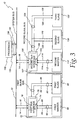
- FIG. 3 is a schematic block diagram of one form of integrated circuit made in accordance with the invention and employing 3-way bus interfaces.
- Figure 4 is a schematic block diagram of one of the 3-way bus interfaces shown in Fig. 3.
- an integrated circuit system 70 employing an SoC includes a first bus interface 72, which may include a bridge.
- the word "interface” is used in the sense described in The Authoritative Dictionary Of IEEE Standards Terms (IEEE Press 2000), p. 574 “(4) A shared boundary.”
- the word “bridge” is used in the sense described in The Authoritative Dictionary Of IEEE Standards Terms (IEEE Press 2000), p. 119 “(4) A hardware adapter that forwards transactions between buses.”
- a bus interface can be used as a bridge between a relatively simple bus and a relatively complex bus.
- Interface 72 also includes a master port 74, a slave port 75 and a bus port 76, and handles communication with a first master device 80.
- Master device 80 may be implemented, for example, by a processor (such as processor 130), or an MPEG decoder, and may be coupled to the other end of a bridge.
- Interface 72 is coupled to system bus 12 through port 76 and is coupled to device 80 through a first master bus 82, which includes an address bus 84 and a data bus 86.
- a first slave device 90 is coupled to port 75 of interface 72 by a first slave bus 92, which includes an address bus 94 and a data bus 96.
- Slave 90 may be an end user, a generator of data, or a bridge to another bus that is coupled to an end user.
- Coupled includes coupling between devices that can communicate through intermediate devices.
- master 80 is coupled to slave 90 through bus 82, interface 72 and bus 92.
- a second bus interface 102 which may include a bridge, includes a master port 104, a slave port 105 and a bus port 106.
- Interface 102 is coupled to system bus 12 through port 106 and is coupled to a second master device 110 through a second master bus 112 that includes an address bus 114 and a data bus 116.
- Interface 102 communicates with a second slave device 120 and a third slave device 122 through a second slave bus 124, which includes an address bus 126 and a data bus 128.
- a processor device 130 such as a digital signal processor, is coupled to system bus 12 through a bus 132 comprising an address bus 134 and a data bus 136.
- Processor 130 may operate as a master with respect to slaves 90, 120 and 122.
- Fig. 4 illustrates 3-way interface 72 in more detail. Interface 72 could be built in a number of ways. Fig. 4 shows one possible implementation of interface 72, but other implementations are possible. An exemplary functionality of interface 72 includes:
- a bus interface 140 is coupled through a second master bus 142, which includes an address bus 144 and a data bus 146, to a first bridge 150 that is coupled to device 80 through bus 82.
- a bus interface 160 is coupled through a third slave bus 162, which includes an address bus 164 and a data bus 166, to another bridge 170 that is coupled to device 90 through bus 92.
- interfaces 140 and 160 can be omitted, and the system bus 12 can be connected to bridges 150 and 170.
- Bridge 150 is coupled to bridge 170 through a second slave bus 172, which includes an address bus 174 and a data bus 176.
- Interface 102 (Fig. 3) is identical to interface 72 and may be understood with reference to Fig. 4.
- System bus 12 has a first complexity, and the remaining busses 82, 92, 112, 124, 142, 162 and 172 have a second complexity less than the first complexity.
- the second complexity of busses 82, 92, 112, 124, 142, 162 and 172 may all be the same.
- System bus 12 is a multiple-master bus that is a complex bus, and busses 82, 92, 112, 124, 142, 162 and 172 are single-master busses that are simple busses.
- Bus 12 operates in a plurality of first states that includes one or more of the states of address, data, idle, arbitration, errors, configuration, timing, bursts, termination and interrupts.
- Busses 82, 92, 112, 124, 142, 162 and 172 operate in a plurality of second states different from the first states.
- the second states are a subset of the first states.
- Interfaces 72 and 102 (Fig. 3), as well as bridges within the interfaces, such as bridges 150 and 170 (Fig. 4), translate between the different states in which bus 12 and the remaining busses 82, 92, 112, 124, 142, 162 and 172 operate.
- any master in system 70 may send data to or receive data from any other slave in system 70.
- Any slave in system 70 may send data to or receive data from any master.
- first bridge 150 responds to an address from master 80
- second bridge 170 responds to an address from system bus 12.
- master 80 generates a first address and first data and the first bridge 150 directs the first data to system bus 12 or second bridge 170 in response to the first address.
- the system bus 12 may transmit a second address and second data. If so, the second bridge 170 directs the first data to slave 90 in response to the first address and directs the second data to the slave 90 in response to the second address.
- a module it is possible for a module to be both a bus master and a bus slave.
- Interface 72 for example, is both a system bus master and a system bus slave.
- the method embodiment of the invention is useful in an integrated circuit system comprising plurality of devices, such as masters 80 and 110 , slaves 90, 120 and 122 and processor 130.
- the devices are interconnected by a first bus, such as system bus 12, and one or more second busses, such as busses 82 and 92 or 112 and 124 (Fig. 3), or busses 82, 92, 142, 162 and 172 (Fig. 4).
- Data is transmitted among the plurality of devices with reference to an address associated with the data, such as an address transmitted on any of the previously described address busses.
- System bus 12 is operated at a first complexity
- the second busses are operated at a second complexity less than the first complexity. There is translation between the first complexity and the second complexity so that the data is routed on the first bus and one or more second busses in response to the address or is routed only on the one or more second busses in response to the address.
- System bus 12 may be operated in a first plurality of states and the one or more second busses may be operated in a second plurality of states different from the first plurality of states. If so, the translating comprises translating between the first plurality of states and the second plurality of states.
- the first plurality of states for bus 12 include one or more of address, data, idle, arbitration, errors, configuration, timing, bursts, termination and interrupts.
- Busses 82, 92, 112, 124, 142, 162 and 172 operate in a plurality of second states different from the first states. The second states are a subset of the first states.
- Three-way interfaces like interfaces 72 and 102, are known in the art, but their use in connection with a system bus and various simple or single-master busses as shown in the drawings is believed to be novel, and offers a number of advantages.
- Interface 72 handles the complexity of the system bus at the local bus level.
- the local busses include busses 82, 92, 112, 124, 142, 162 and 172.
- a local bus is generally much easier to deal with than system bus 12.
- the bridge solution illustrated in Fig. 2 has multiple system bus segments. This generally requires a complex system bus protocol (such as backoff/retry) to handle resource conflicts.
- the embodiment shown in Figs. 3-4 does not require this capability from the system bus.
- N N system bus segments.
- the worst-case transaction could traverse (N-1) bridges, each with backoff/retry. This path could take a very long time, and could be very difficult to analyze.
- Figs. 3-4 Local (intra-block) accesses in a segmented-bus system depend on the system bus topology and protocol. In the embodiment illustrated in Figs. 3-4, local access times are guaranteed by the bus interface 72. The embodiment of Figs. 3-4 allows blocks with local accesses to be verified independent of the system. (This is a substantial benefit.)
- the local busses 82, 92, 112, 124, 142, 162 and 172 are relatively simple. Bridges for the local busses, such as bridges 150 and 172, are much easier to build than bridges for the system bus 12. For simple single-master local busses, the local bus bridges may only require a few thousand gates.
- Timing within a block is analyzable.
- the worst-case local access time is twice the worst-case local slave response time. (Once for a system bus access, and once for the local access.) This worst-case time is independent of the system bus protocol or topology.
- each block may be verified independent of the rest of the system. Blocks do not need re-verification if the system bus topology changes.
- the system has global access. Any master may access any slave over the system bus. (Unless specific restrictions are added.)
- the system has no immediate resource conflicts. No bus master is ever required to "backoff" the system bus due to a resource conflict. (This greatly simplifies the protocol requirements of the system bus.)
- the loading of the system bus is significantly reduced. There are fewer modules on the system bus, and local (intra-block) traffic is kept off the system bus.
- the architecture is easy to use.
- the only blocks that need to deal with the complex system bus protocol are the 3-way bus interfaces 72 and 102. All other modules or blocks use the simple interface.
- system bus 12 can be segmented, bridged, or switched without affecting the structure of the blocks. But, complex switching of the system bus 12 is usually not required.
Landscapes
- Engineering & Computer Science (AREA)
- General Engineering & Computer Science (AREA)
- Theoretical Computer Science (AREA)
- Computer Hardware Design (AREA)
- Physics & Mathematics (AREA)
- General Physics & Mathematics (AREA)
- Bus Control (AREA)
- Information Transfer Systems (AREA)
Abstract
Description
Claims (10)
- In an integrated circuit system comprising a system bus with a first complexity, apparatus for enabling communication among a plurality of devices in part through the system bus comprising:at least a first device;at least a second device; anda bus interface coupled to the system bus, coupled to the first device through a first bus with a second complexity less than the first complexity.
- The apparatus of claim 1, the bus interface coupled to the system bus, coupled to the first device through the first bus with the second complexity less than the first complexity, further being coupled to the second device through a second bus with a third complexity less than the first complexity.
- The apparatus of claim 2 wherein the system bus is arranged to operate in a first plurality of states, wherein the first bus and second bus each are arranged to operate in a second plurality of states different from the first plurality of states and wherein the bus interface comprises a bridge arranged to translate between the first states and the second states.
- The apparatus of claim 3 wherein the first plurality of states comprises one or more states for address, data, idle, arbitration, errors, configuration, timing, bursts, termination and interrupts and wherein the second plurality of states comprises a subset of the first plurality of states.
- The apparatus of any of the claims 2 to 4 wherein the bus interface comprises:a first bridge coupled to the second device over the second bus and coupled to the system bus over a third bus with a fourth complexity less than the first complexity; anda second bridge coupled to the first device over the first bus, coupled to the first bridge over a fourth bus with a fifth complexity less than the first complexity and coupled to the system bus over a fifth bus with a sixth complexity less than the first complexity.
- The apparatus of claim 5 wherein second complexity, third complexity, fourth complexity, fifth complexity and sixth complexity comprise the same complexity.
- In an integrated circuit system comprising plurality of devices interconnected by a first bus and one or more second busses, a method of transmitting data among the plurality of devices with reference to an address associated with the data comprising:operating the first bus at the first complexity;operating the one or more second busses at a second complexity less than the first complexity;translating between the first complexity and the second complexity so that the data is routed on the first bus and the one or more second busses in response to the address or is routed only on the one or more second busses in response to the address.
- The method of claim 7 wherein the first bus is arranged to operate in a first plurality of states and wherein the one or more second busses are arranged to operate in a second plurality of states different from the first plurality of states.
- The method of claim 8 wherein the translating comprises translating between the first plurality of states and the second plurality of states.
- The method of claim 9 wherein the first plurality of states comprises one or more states for address, data, idle, arbitration, errors, configuration, timing, bursts, termination and interrupts and wherein the second plurality of states comprises a subset of the first plurality of states.
Applications Claiming Priority (2)
| Application Number | Priority Date | Filing Date | Title |
|---|---|---|---|
| US437497 | 1982-10-28 | ||
| US10/437,497 US7130953B2 (en) | 2003-03-05 | 2003-05-13 | Bus architecture techniques employing busses with different complexities |
Publications (2)
| Publication Number | Publication Date |
|---|---|
| EP1477904A1 true EP1477904A1 (en) | 2004-11-17 |
| EP1477904B1 EP1477904B1 (en) | 2008-08-13 |
Family
ID=33029791
Family Applications (1)
| Application Number | Title | Priority Date | Filing Date |
|---|---|---|---|
| EP04009344A Expired - Lifetime EP1477904B1 (en) | 2003-05-13 | 2004-04-20 | Bus architecture techniques employing busses with different complexities |
Country Status (3)
| Country | Link |
|---|---|
| US (1) | US7130953B2 (en) |
| EP (1) | EP1477904B1 (en) |
| DE (1) | DE602004015667D1 (en) |
Families Citing this family (8)
| Publication number | Priority date | Publication date | Assignee | Title |
|---|---|---|---|---|
| US7010641B2 (en) * | 2003-01-31 | 2006-03-07 | Agilent Technologies, Inc. | Integrated circuit routing resource optimization algorithm for random port ordering |
| JP4233373B2 (en) * | 2003-04-14 | 2009-03-04 | 株式会社ルネサステクノロジ | Data transfer control device |
| WO2011136796A1 (en) * | 2010-04-30 | 2011-11-03 | Hewlett-Packard Development Company, L.P. | Management data transfer between processors |
| KR20120097831A (en) * | 2011-02-25 | 2012-09-05 | 삼성전자주식회사 | System on chip bus system |
| US9934184B1 (en) * | 2015-09-25 | 2018-04-03 | Amazon Technologies, Inc. | Distributed ordering system |
| US10255210B1 (en) | 2016-03-01 | 2019-04-09 | Amazon Technologies, Inc. | Adjusting order of execution of a target device |
| EP3819778A1 (en) | 2019-11-07 | 2021-05-12 | Ams Ag | Bus system and method for operating a bus system |
| US11494329B2 (en) * | 2020-02-27 | 2022-11-08 | Advantest Corporation | NVMe-MI over SMBus multi-master controller with other SMBus and I2C masters in a single FPGA chip |
Family Cites Families (10)
| Publication number | Priority date | Publication date | Assignee | Title |
|---|---|---|---|---|
| DE4317567A1 (en) * | 1993-05-26 | 1994-12-01 | Siemens Ag | Method for operating a bus system and arrangement for carrying out the method |
| US5727172A (en) * | 1995-05-01 | 1998-03-10 | Motorola, Inc. | Method and apparatus for performing atomic accesses in a data processing system |
| US5812800A (en) * | 1995-09-11 | 1998-09-22 | Advanced Micro Devices, Inc. | Computer system which includes a local expansion bus and a dedicated real-time bus and including a multimedia memory for increased multi-media performance |
| GB2332344A (en) * | 1997-12-09 | 1999-06-16 | Sony Uk Ltd | Set top box integrated circuit |
| US6061764A (en) * | 1998-01-26 | 2000-05-09 | Intel Corporation | Coherent variable length reads which implicates multiple cache lines by a memory controller connected to a serial and a pipelined bus utilizing a plurality of atomic transactions |
| US6112311A (en) * | 1998-02-20 | 2000-08-29 | International Business Machines Corporation | Bridge failover system |
| US6598110B1 (en) * | 1998-11-25 | 2003-07-22 | Texas Instruments Inc | Method and apparatus for data conversion in a computer bus |
| US6532511B1 (en) * | 1999-09-30 | 2003-03-11 | Conexant Systems, Inc. | Asochronous centralized multi-channel DMA controller |
| US6636947B1 (en) * | 2000-08-24 | 2003-10-21 | International Business Machines Corporation | Coherency for DMA read cached data |
| US7356619B2 (en) * | 2002-05-09 | 2008-04-08 | International Business Machines Corporation | Method and apparatus for dynamic management of input/output subsystem addressing |
-
2003
- 2003-05-13 US US10/437,497 patent/US7130953B2/en not_active Expired - Fee Related
-
2004
- 2004-04-20 DE DE602004015667T patent/DE602004015667D1/en not_active Expired - Lifetime
- 2004-04-20 EP EP04009344A patent/EP1477904B1/en not_active Expired - Lifetime
Non-Patent Citations (6)
| Title |
|---|
| "AMBA Specification (Rev 2.0)", 13 May 1999, ARM, XP002288981 * |
| "The CoreConnect Bus Architecture", IBM, 1999, XP002204519 * |
| ALDWORTH P J: "System-on-a-chip bus architecture for embedded applications", COMPUTER DESIGN, 1999. (ICCD '99). INTERNATIONAL CONFERENCE ON AUSTIN, TX, USA 10-13 OCT. 1999, LOS ALAMITOS, CA, USA,IEEE COMPUT. SOC, US, 10 October 1999 (1999-10-10), pages 297 - 298, XP010360495, ISBN: 0-7695-0406-X * |
| FLYNN D: "AMBA: ENABLING REUSABLE ON-CHIP DESIGNS", IEEE MICRO, IEEE INC. NEW YORK, US, vol. 17, no. 4, 1 July 1997 (1997-07-01), pages 20 - 27, XP000658531, ISSN: 0272-1732 * |
| MIPS: "MIPS SOC-it(TM) 101 System Controller Family Datasheet", 30 November 2002, MIPS TECHNOLOGIES INC., INTERNET, XP002288979 * |
| MIPS: "SOC-it Press Presentation", 29 July 2002, MIPS TECHNOLOGIES INC., INTERNET, XP002288980 * |
Also Published As
| Publication number | Publication date |
|---|---|
| US7130953B2 (en) | 2006-10-31 |
| US20040177205A1 (en) | 2004-09-09 |
| DE602004015667D1 (en) | 2008-09-25 |
| EP1477904B1 (en) | 2008-08-13 |
Similar Documents
| Publication | Publication Date | Title |
|---|---|---|
| US5828865A (en) | Dual mode bus bridge for interfacing a host bus and a personal computer interface bus | |
| US5933610A (en) | Predictive arbitration system for PCI bus agents | |
| US7506089B2 (en) | Bus system and method thereof | |
| US6108738A (en) | Multi-master PCI bus system within a single integrated circuit | |
| US6816938B2 (en) | Method and apparatus for providing a modular system on-chip interface | |
| US20050071533A1 (en) | System resource router | |
| US6981088B2 (en) | System and method of transferring data words between master and slave devices | |
| US7475182B2 (en) | System-on-a-chip mixed bus architecture | |
| CN100557589C (en) | Advanced microcontroller bus architecture system with reduced power consumption and driving method thereof | |
| US6633944B1 (en) | AHB segmentation bridge between busses having different native data widths | |
| KR19990077461A (en) | Method and system for supporting multiple peripheral component interconnect (pci) buses by a single pci bridge within a computer system | |
| US7107365B1 (en) | Early detection and grant, an arbitration scheme for single transfers on AMBA advanced high-performance bus | |
| US5867645A (en) | Extended-bus functionality in conjunction with non-extended-bus functionality in the same bus system | |
| EP1477904B1 (en) | Bus architecture techniques employing busses with different complexities | |
| KR102865968B1 (en) | Data communication with enhanced speed mode | |
| US20120221754A1 (en) | System on chip bus system and a method of operating the bus system | |
| US6687773B1 (en) | Bridge for coupling digital signal processor to on-chip bus as master | |
| KR100291409B1 (en) | Method and apparatus for supporting two secondary decode agents on the same bus in a computer system | |
| US20030188071A1 (en) | On-chip high speed data interface | |
| KR100963706B1 (en) | Data transmission method, data transmission bridge and high speed data transmission device | |
| US7945806B2 (en) | Data processing apparatus and method for controlling a transfer of payload data over a communication channel | |
| US20080172510A1 (en) | Parallel bus architecture and related method for interconnecting sub-systems utilizing a parallel bus | |
| US6912609B2 (en) | Four-phase handshake arbitration | |
| CN119576537A (en) | Peripheral integrated system, writing method, reading method, instantiation method and chip | |
| US11995007B1 (en) | Multi-port, multi-protocol varied size RAM controller |
Legal Events
| Date | Code | Title | Description |
|---|---|---|---|
| PUAI | Public reference made under article 153(3) epc to a published international application that has entered the european phase |
Free format text: ORIGINAL CODE: 0009012 |
|
| AK | Designated contracting states |
Kind code of ref document: A1 Designated state(s): AT BE BG CH CY CZ DE DK EE ES FI FR GB GR HU IE IT LI LU MC NL PL PT RO SE SI SK TR |
|
| AX | Request for extension of the european patent |
Extension state: AL HR LT LV MK |
|
| 17P | Request for examination filed |
Effective date: 20050517 |
|
| AKX | Designation fees paid |
Designated state(s): DE FR GB |
|
| 17Q | First examination report despatched |
Effective date: 20060208 |
|
| RAP1 | Party data changed (applicant data changed or rights of an application transferred) |
Owner name: BROADCOM CORPORATION |
|
| GRAP | Despatch of communication of intention to grant a patent |
Free format text: ORIGINAL CODE: EPIDOSNIGR1 |
|
| GRAS | Grant fee paid |
Free format text: ORIGINAL CODE: EPIDOSNIGR3 |
|
| GRAA | (expected) grant |
Free format text: ORIGINAL CODE: 0009210 |
|
| AK | Designated contracting states |
Kind code of ref document: B1 Designated state(s): DE FR GB |
|
| REG | Reference to a national code |
Ref country code: GB Ref legal event code: FG4D |
|
| REF | Corresponds to: |
Ref document number: 602004015667 Country of ref document: DE Date of ref document: 20080925 Kind code of ref document: P |
|
| PLBE | No opposition filed within time limit |
Free format text: ORIGINAL CODE: 0009261 |
|
| STAA | Information on the status of an ep patent application or granted ep patent |
Free format text: STATUS: NO OPPOSITION FILED WITHIN TIME LIMIT |
|
| 26N | No opposition filed |
Effective date: 20090514 |
|
| REG | Reference to a national code |
Ref country code: FR Ref legal event code: ST Effective date: 20091231 |
|
| PG25 | Lapsed in a contracting state [announced via postgrant information from national office to epo] |
Ref country code: FR Free format text: LAPSE BECAUSE OF NON-PAYMENT OF DUE FEES Effective date: 20091222 |
|
| PGFP | Annual fee paid to national office [announced via postgrant information from national office to epo] |
Ref country code: GB Payment date: 20130422 Year of fee payment: 10 |
|
| GBPC | Gb: european patent ceased through non-payment of renewal fee |
Effective date: 20140420 |
|
| PG25 | Lapsed in a contracting state [announced via postgrant information from national office to epo] |
Ref country code: GB Free format text: LAPSE BECAUSE OF NON-PAYMENT OF DUE FEES Effective date: 20140420 |
|
| REG | Reference to a national code |
Ref country code: DE Ref legal event code: R082 Ref document number: 602004015667 Country of ref document: DE Representative=s name: BOSCH JEHLE PATENTANWALTSGESELLSCHAFT MBH, DE Ref country code: DE Ref legal event code: R081 Ref document number: 602004015667 Country of ref document: DE Owner name: AVAGO TECHNOLOGIES INTERNATIONAL SALES PTE. LT, SG Free format text: FORMER OWNER: BROADCOM CORP., IRVINE, CALIF., US Ref country code: DE Ref legal event code: R081 Ref document number: 602004015667 Country of ref document: DE Owner name: AVAGO TECHNOLOGIES GENERAL IP (SINGAPORE) PTE., SG Free format text: FORMER OWNER: BROADCOM CORP., IRVINE, CALIF., US |
|
| REG | Reference to a national code |
Ref country code: DE Ref legal event code: R082 Ref document number: 602004015667 Country of ref document: DE Representative=s name: BOSCH JEHLE PATENTANWALTSGESELLSCHAFT MBH, DE Ref country code: DE Ref legal event code: R081 Ref document number: 602004015667 Country of ref document: DE Owner name: AVAGO TECHNOLOGIES INTERNATIONAL SALES PTE. LT, SG Free format text: FORMER OWNER: AVAGO TECHNOLOGIES GENERAL IP (SINGAPORE) PTE. LTD., SINGAPORE, SG |
|
| PGFP | Annual fee paid to national office [announced via postgrant information from national office to epo] |
Ref country code: DE Payment date: 20230411 Year of fee payment: 20 |
|
| REG | Reference to a national code |
Ref country code: DE Ref legal event code: R071 Ref document number: 602004015667 Country of ref document: DE |