EP1477742A1 - Joint in a fireplace - Google Patents
Joint in a fireplace Download PDFInfo
- Publication number
- EP1477742A1 EP1477742A1 EP04396035A EP04396035A EP1477742A1 EP 1477742 A1 EP1477742 A1 EP 1477742A1 EP 04396035 A EP04396035 A EP 04396035A EP 04396035 A EP04396035 A EP 04396035A EP 1477742 A1 EP1477742 A1 EP 1477742A1
- Authority
- EP
- European Patent Office
- Prior art keywords
- joint
- locking part
- locking
- groove
- planar surface
- Prior art date
- Legal status (The legal status is an assumption and is not a legal conclusion. Google has not performed a legal analysis and makes no representation as to the accuracy of the status listed.)
- Granted
Links
- 239000004575 stone Substances 0.000 claims abstract description 40
- 230000008878 coupling Effects 0.000 claims abstract description 24
- 238000010168 coupling process Methods 0.000 claims abstract description 24
- 238000005859 coupling reaction Methods 0.000 claims abstract description 24
- 239000000463 material Substances 0.000 claims abstract description 10
- 238000005304 joining Methods 0.000 claims abstract description 6
- 239000002184 metal Substances 0.000 claims description 14
- 229910052751 metal Inorganic materials 0.000 claims description 14
- XEEYBQQBJWHFJM-UHFFFAOYSA-N Iron Chemical compound [Fe] XEEYBQQBJWHFJM-UHFFFAOYSA-N 0.000 claims description 6
- 229910052742 iron Inorganic materials 0.000 claims description 2
- 238000003754 machining Methods 0.000 description 2
- 238000003825 pressing Methods 0.000 description 2
- 229910001018 Cast iron Inorganic materials 0.000 description 1
- 229910001208 Crucible steel Inorganic materials 0.000 description 1
- 238000010420 art technique Methods 0.000 description 1
- 229910010293 ceramic material Inorganic materials 0.000 description 1
- 230000009970 fire resistant effect Effects 0.000 description 1
- 238000003780 insertion Methods 0.000 description 1
- 230000037431 insertion Effects 0.000 description 1
- 238000004519 manufacturing process Methods 0.000 description 1
- 239000010959 steel Substances 0.000 description 1
Images

Classifications
-
- F—MECHANICAL ENGINEERING; LIGHTING; HEATING; WEAPONS; BLASTING
- F24—HEATING; RANGES; VENTILATING
- F24B—DOMESTIC STOVES OR RANGES FOR SOLID FUELS; IMPLEMENTS FOR USE IN CONNECTION WITH STOVES OR RANGES
- F24B1/00—Stoves or ranges
- F24B1/02—Closed stoves
- F24B1/04—Closed stoves built-up from glazed tiles
- F24B1/06—Construction of tiles or bracing means therefor, e.g. shim liner
Definitions
- the invention relates to a joint to be used in a fireplace as defined in the preamble of claim 1 for joining a stone part and a structural part made of other material with one another.
- FI 96347 in which a sheet-like hook is fixed to one longitudinal and two transverse grooves
- FI 83559 in which a sheet-like, curved hook, provided with end pegs, is inserted into a longitudinal groove and two borings
- FI 101491 in which an elongated, sheet-like metal strip provided with gripping projections is inserted into an elongated groove so that the metal strip engages the edges of the groove. All these are functional structures per se, but only applicable to the joining of two stone elements, and particularly soapstone elements, straight and directly with each other.
- the objective of the invention is to eliminate the drawbacks referred to above.
- One specific objective of the invention is to disclose a new type of joint to be used in fireplaces between a stone part and a structural part made of other material, which enables a faster and more cost-efficient making of the joint and which makes the joint tighter and firmer, enabling the use of more simple and thus more advantageous joint parts and minimising the machining of the stone parts to be handled.
- the invention relates to a joint in a fireplace for joining a stone part and a structural part made of other material with one another.
- the other material usually consists of metal, cast iron or steel, but also e.g. various ceramic materials, tiles and other burned clays as well as various fire-resistant masses are possible.
- the stone part to be used in a fireplace includes a first planar surface against which the structural part is joined, and a second planar surface which is at an angle against the first planar surface.
- the second planar surface includes a groove extending away from the structural part and being formed by the edges and the bottom.
- the joint between the stone part and structural part includes an elongated locking part.
- the first planar surface and the second planar surface of the stone part preferably are perpendicular to each other, and preferably the planar surfaces have a common sharp edge, from which they extend into different directions at an angle of 90 degrees with respect to each other.
- the stone part functions a stone part in the shape of a rectangular parallelepiped.
- the first end of the elongated locking part includes a coupling element and the structural part includes a counterpart of the coupling element for locking the locking part and the structural part rigidly with respect to one another in the longitudinal direction of the locking part.
- the coupling element and the counterpart lock the locking part into the structural part in the longitudinal direction of the locking part inflexibly rigidly and non-yieldingly.
- substantially the one end of the locking part includes at least one edge tightening element for implementing the longitudinal tightening fastening of the locking part in the edge of the groove.
- the coupling element consists of a rigid fold of the locking part, preferably a fold of 90 degrees in the elongated locking part.
- a rigid fold of the locking part preferably a fold of 90 degrees in the elongated locking part.
- the coupling element consists of a rigid hook, groove or notch, i.e. a suitable shape deviating from straight and uniform and enabling a sufficient gripping between the joint part and the structural part.
- the counterpart of the coupling element consists of a hole, opening, projection or shoulder in the structural part to which the coupling element can be coupled.
- the locking part includes at least two opposite edge tightening elements for implementing the tightening fastening in both edges of the groove. It is also possible that there are several edge tightening elements on opposite sides of the locking part so that the fastening, tightening and locking of the locking part, and through it that of the structural part, can be implemented along a long stretch in both edges of the groove. It must also be noted that, depending on the locking part, it is possible to use in the invention even a rather low groove, and this groove can always be equal in depth, i.e. the bottom of the groove can be a straight one because the locking and fastening are performed by pressing into the edges of the grooves and not into the borings made on the bottom of the groove, as in the prior-art technique.
- the edge tightening element consists of a projection, protuberance, edge or peg, which as being partly supported on the groove edge, implements the tightening fastening. It is possible to use any sharp edges known per se that are perpendicular or at a slight oblique angle with respect to the groove to be locked for implementing a suitable locking and tightening. Also variously shaped projections and protuberances may have particular shapes, or figures or series implementing the desired locking and tightening functions may have been formed of them.
- the locking part consists of a metal strip such as e.g. a flat iron, whose first end has been shaped to form the desired coupling element and which has at its second end, or at least farther from the first end, one or more edge tightening elements.
- a metal strip such as e.g. a flat iron, whose first end has been shaped to form the desired coupling element and which has at its second end, or at least farther from the first end, one or more edge tightening elements.
- the locking part consists of a metal bar such as a sufficiently thick and rigid metal wire.
- the groove in the second planar surface can be curved or complicated, it preferably is a straight groove which is easy and simple to machine.
- the straight groove preferably is at a right angle, i.e. perpendicular to the second planar surface, although an oblique groove is not an excluded embodiment of the invention.
- the joint to be used in fireplaces as defined in the invention has considerable advantages over prior art.
- the joints between the stone part of the fireplace and structural parts made of other material can be made tight and firm.
- the joints are easy and simple to make.
- the locking parts to be used are simple and advantageous, and mounting them is fast with no need for specific tools, just by hammering.
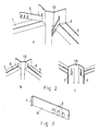
- Fig. 1 shows four different phases of the fact of how a metallic, sheet-like structural part 2 is fastened and joined with a stone part 1 having the shape of a rectangular parallelepiped.
- the stone part 1 includes a first straight planar surface 3, against which the sheet-like structural part 2 is fastened, and a second straight planar surface 4, which is perpendicular to the first planar surface 3.
- Machined on the surface of the second planar surface 4 is a groove 5 of a substantially uniform depth, which is perpendicular to the first planar surface 3, as well as perpendicular to the surface of the sheet-like structural part that comes against the stone part.
- the locking part 6 to be used consists of a flat iron part having at the first end thereof a short fold of 90 degrees which forms a coupling element 7.
- a coupling element 7 Arranged in the vicinity of the second end of the locking part 6, on its both planar and wide outer surfaces, are three edge tightening elements 9, i.e. sharp edged ridges, which are at a slight angle with respect to the transverse direction of the elongated locking part.
- the planar part of the metallic sheet-like structural part that comes against the first planar surface 3 includes, as a counterpart 8 of the coupling element 7, a narrow vertical opening through which the coupling element can be inserted inside, i.e. through the opening.
- a coupling element 7 is inserted into the counterpart 8, after which the locking part 6 is turned (Fig. c) so as to be in parallel to the groove 5 on top of it, and is stretched on top of the stone part 1 as far as possible so that the parts to be attached 1 and 2 come joined with one another along their entire corresponding surfaces.
- the locking part 6 is hit e.g. with a hammer substantially straight inside the groove 5.
- the edge tightening elements 9 engage the opposite edges of the groove, and due to the slight obliqueness of these, pull and tighten the structural part 2 tightly into the planar surface 3. A tidy, fast and firm joint is achieved.
- Fig. 2 shows another embodiment of the invention in which there are two stone parts 1, and the joint is designed to join these two stone parts with one another at a right angle using an angle profile 10.
- the locking parts 6 are attached to the counterparts of the coupling elements that are disposed in the angle profile, i.e. the narrow, elongated openings (Fig. a).
- the stone parts 1 and the angle profile 2 between them are in place (Fig. b)
- the locking parts 6 are hit into the grooves 5 corresponding to them, whereby the edge tightening elements tighten and lock the stone parts 1 and the angle profile 2 into each other.
- the counterparts of the coupling elements i.e. the elongated openings in the angle profile, are relatively long with respect to the corresponding width of the locking part 6, substantially double. These openings extend partly into the area of the stone part to be fastened and partly above it. In this manner, the insertion of the locking parts into the openings is successful also when both the stone part and the structural part to be fastened to it already are in place.
- Fig. 3 shows in more detail one locking part 6 to be used in a joint in accordance with the invention.
- the flat iron part i.e. the straight, planar, thin and narrow metal strip
- the flat iron part is, from its one end, turned into a right angle through a short distance, to form at the first end thereof a coupling element 7.
- edge tightening elements 9 consist of straight and sharp edged ridges or projections whose straight lines are in parallel with one another. These lines are at a slightly oblique angle from the vertical direction with respect to the longitudinal direction of the locking part for implementing the desired tightening locking when hitting the locking part into the groove of the stone.
Landscapes
- Engineering & Computer Science (AREA)
- Chemical & Material Sciences (AREA)
- Combustion & Propulsion (AREA)
- Mechanical Engineering (AREA)
- General Engineering & Computer Science (AREA)
- Finishing Walls (AREA)
- Ceramic Products (AREA)
- Crystals, And After-Treatments Of Crystals (AREA)
- Processing Of Stones Or Stones Resemblance Materials (AREA)
- Adhesives Or Adhesive Processes (AREA)
- Inorganic Insulating Materials (AREA)
- Led Device Packages (AREA)
Abstract
Description
- The invention relates to a joint to be used in a fireplace as defined in the preamble of
claim 1 for joining a stone part and a structural part made of other material with one another. - The closest prior art in the field of the invention represent Finnish patents FI 87687, FI 87688, FI 87689, FI 88070 and FI 89304. All these patent publications disclose different angle structures of fireplaces in which two cornerwise placed stone parts are joined with each other from the corner using a suitably shaped metal profile, which is fixed to the stone element using various hooks or the like. The fixing of the hooks in the stone element has been performed first in a longitudinal groove and at the end in a vertical boring. The fixing of the metal profile has been implemented in many different flexible and locking manners.
- Common to all the prior-art structures, besides the longitudinal groove, is the need for a transverse boring and a rigid locking into the stone. In addition, all the tightening, pressing and locking are implemented at the end of the hook that is situated on the side of the metal profile.
- Several problems are associated with the prior art. Longitudinal grooves and transverse borings or grooves have to be machined in the stone, which makes the machining of the stone both slow and costly. Most of the prior-art hooks consist of two or more parts, making their manufacturing costs high. Similarly, the use, mounting in place and tightening of hooks consisting of more than one part is slow, thus incurring additional costs.
- Known in the field are also various locking hooks and locking strips which are designed for fixing two adjacent stone elements directly to each other. As an example of these we mention FI 96347 in which a sheet-like hook is fixed to one longitudinal and two transverse grooves; FI 83559 in which a sheet-like, curved hook, provided with end pegs, is inserted into a longitudinal groove and two borings; as well as FI 101491 in which an elongated, sheet-like metal strip provided with gripping projections is inserted into an elongated groove so that the metal strip engages the edges of the groove. All these are functional structures per se, but only applicable to the joining of two stone elements, and particularly soapstone elements, straight and directly with each other.
- Lately, as the structures and structural materials of fireplaces made mainly of stone diversify and as the use of stone becomes common also in conjunction with conventional metallic stoves, there is a need to develop tight joint structures that are very heat-resistant, that enable the joining of stone and a structural part made of other material, such as metal, with one another, sufficiently firmly and fixedly.
- The objective of the invention is to eliminate the drawbacks referred to above. One specific objective of the invention is to disclose a new type of joint to be used in fireplaces between a stone part and a structural part made of other material, which enables a faster and more cost-efficient making of the joint and which makes the joint tighter and firmer, enabling the use of more simple and thus more advantageous joint parts and minimising the machining of the stone parts to be handled.
- As for the features characteristic of the invention, reference is made to them in the claims.
- The invention relates to a joint in a fireplace for joining a stone part and a structural part made of other material with one another. The other material usually consists of metal, cast iron or steel, but also e.g. various ceramic materials, tiles and other burned clays as well as various fire-resistant masses are possible. The stone part to be used in a fireplace includes a first planar surface against which the structural part is joined, and a second planar surface which is at an angle against the first planar surface. The second planar surface includes a groove extending away from the structural part and being formed by the edges and the bottom. The joint between the stone part and structural part includes an elongated locking part.
- The first planar surface and the second planar surface of the stone part preferably are perpendicular to each other, and preferably the planar surfaces have a common sharp edge, from which they extend into different directions at an angle of 90 degrees with respect to each other. Thus, for example, as the stone part functions a stone part in the shape of a rectangular parallelepiped.
- According to the invention, the first end of the elongated locking part includes a coupling element and the structural part includes a counterpart of the coupling element for locking the locking part and the structural part rigidly with respect to one another in the longitudinal direction of the locking part. In this manner, the coupling element and the counterpart lock the locking part into the structural part in the longitudinal direction of the locking part inflexibly rigidly and non-yieldingly. Furthermore, according to the invention, substantially the one end of the locking part includes at least one edge tightening element for implementing the longitudinal tightening fastening of the locking part in the edge of the groove.
- In one embodiment of the invention, the coupling element consists of a rigid fold of the locking part, preferably a fold of 90 degrees in the elongated locking part. When the counterpart of the structural part made of other material is correctly shaped to correspond to a straight fold, i.e. it has a suitable sharp edge behind which the straight fold can be supported, a firm and rigid coupling between the joint part and the structural part can be easily implemented.
- In another embodiment of the invention, the coupling element consists of a rigid hook, groove or notch, i.e. a suitable shape deviating from straight and uniform and enabling a sufficient gripping between the joint part and the structural part.
- In one embodiment of the invention, the counterpart of the coupling element consists of a hole, opening, projection or shoulder in the structural part to which the coupling element can be coupled.
- In a preferred embodiment of the invention, the locking part includes at least two opposite edge tightening elements for implementing the tightening fastening in both edges of the groove. It is also possible that there are several edge tightening elements on opposite sides of the locking part so that the fastening, tightening and locking of the locking part, and through it that of the structural part, can be implemented along a long stretch in both edges of the groove. It must also be noted that, depending on the locking part, it is possible to use in the invention even a rather low groove, and this groove can always be equal in depth, i.e. the bottom of the groove can be a straight one because the locking and fastening are performed by pressing into the edges of the grooves and not into the borings made on the bottom of the groove, as in the prior-art technique.
- Advantageously, the edge tightening element consists of a projection, protuberance, edge or peg, which as being partly supported on the groove edge, implements the tightening fastening. It is possible to use any sharp edges known per se that are perpendicular or at a slight oblique angle with respect to the groove to be locked for implementing a suitable locking and tightening. Also variously shaped projections and protuberances may have particular shapes, or figures or series implementing the desired locking and tightening functions may have been formed of them.
- In one embodiment of the invention, the locking part consists of a metal strip such as e.g. a flat iron, whose first end has been shaped to form the desired coupling element and which has at its second end, or at least farther from the first end, one or more edge tightening elements.
- In another embodiment of the invention, the locking part consists of a metal bar such as a sufficiently thick and rigid metal wire.
- While the groove in the second planar surface can be curved or complicated, it preferably is a straight groove which is easy and simple to machine. Similarly, the straight groove preferably is at a right angle, i.e. perpendicular to the second planar surface, although an oblique groove is not an excluded embodiment of the invention.
- The joint to be used in fireplaces as defined in the invention has considerable advantages over prior art. The joints between the stone part of the fireplace and structural parts made of other material can be made tight and firm. The joints are easy and simple to make. The locking parts to be used are simple and advantageous, and mounting them is fast with no need for specific tools, just by hammering. Apart from the one longitudinal groove, no other grooves or borings need to be machined in the stone parts as this longitudinal groove usually is ready in the stone parts to be used.
- In the following, the invention will be described in more detail with reference to the accompanying drawings, in which
- Fig. 1 represents different mounting phases of one embodiment of the invention;
- Fig. 2 represents different mounting phases of another embodiment of the invention; and
- Fig. 3 represents one locking part in accordance with the invention.
-
- Fig. 1 shows four different phases of the fact of how a metallic, sheet-like
structural part 2 is fastened and joined with astone part 1 having the shape of a rectangular parallelepiped. Thestone part 1 includes a first straightplanar surface 3, against which the sheet-likestructural part 2 is fastened, and a second straightplanar surface 4, which is perpendicular to the firstplanar surface 3. Machined on the surface of the secondplanar surface 4 is agroove 5 of a substantially uniform depth, which is perpendicular to the firstplanar surface 3, as well as perpendicular to the surface of the sheet-like structural part that comes against the stone part. - The
locking part 6 to be used consists of a flat iron part having at the first end thereof a short fold of 90 degrees which forms acoupling element 7. Arranged in the vicinity of the second end of thelocking part 6, on its both planar and wide outer surfaces, are three edge tightening elements 9, i.e. sharp edged ridges, which are at a slight angle with respect to the transverse direction of the elongated locking part. - The planar part of the metallic sheet-like structural part that comes against the first
planar surface 3 includes, as acounterpart 8 of thecoupling element 7, a narrow vertical opening through which the coupling element can be inserted inside, i.e. through the opening. - When fastening the
structural part 2, which is e.g. a metallic back plate of a stove provided with a stone covering, into the stone part 1 (Fig. b), acoupling element 7 is inserted into thecounterpart 8, after which thelocking part 6 is turned (Fig. c) so as to be in parallel to thegroove 5 on top of it, and is stretched on top of thestone part 1 as far as possible so that the parts to be attached 1 and 2 come joined with one another along their entire corresponding surfaces. After this (Fig. d), thelocking part 6 is hit e.g. with a hammer substantially straight inside thegroove 5. In that case, the edge tightening elements 9 engage the opposite edges of the groove, and due to the slight obliqueness of these, pull and tighten thestructural part 2 tightly into theplanar surface 3. A tidy, fast and firm joint is achieved. - Fig. 2 shows another embodiment of the invention in which there are two
stone parts 1, and the joint is designed to join these two stone parts with one another at a right angle using anangle profile 10. Herein, in a manner as shown in Fig. 1, the lockingparts 6 are attached to the counterparts of the coupling elements that are disposed in the angle profile, i.e. the narrow, elongated openings (Fig. a). When thestone parts 1 and theangle profile 2 between them are in place (Fig. b), the lockingparts 6 are hit into thegrooves 5 corresponding to them, whereby the edge tightening elements tighten and lock thestone parts 1 and theangle profile 2 into each other. - As can be seen particularly from Fig. c, the counterparts of the coupling elements, i.e. the elongated openings in the angle profile, are relatively long with respect to the corresponding width of the locking
part 6, substantially double. These openings extend partly into the area of the stone part to be fastened and partly above it. In this manner, the insertion of the locking parts into the openings is successful also when both the stone part and the structural part to be fastened to it already are in place. - Fig. 3 shows in more detail one locking
part 6 to be used in a joint in accordance with the invention. The flat iron part, i.e. the straight, planar, thin and narrow metal strip, is, from its one end, turned into a right angle through a short distance, to form at the first end thereof acoupling element 7. In the vicinity of the second end thereof, on its both planar surfaces, are three edge tightening elements 9. They consist of straight and sharp edged ridges or projections whose straight lines are in parallel with one another. These lines are at a slightly oblique angle from the vertical direction with respect to the longitudinal direction of the locking part for implementing the desired tightening locking when hitting the locking part into the groove of the stone. - In the foregoing, the invention has been described by way of example with reference to the accompanying drawings while various embodiments of the invention are possible within the scope of the inventive idea defined by the claims.
Claims (10)
- A joint in a fireplace for joining a stone part (1) and a structural part (2) made of other material to one another, the stone part including a first planar surface (3, against which the structural part is fastened, and a second planar surface (4), which is at an angle against the first planar surface and which includes a groove (5) extending away from the structural part and being formed by the edges and the bottom, the joint including an elongated locking part (6), characterised in that the first end of the locking part (6) includes a coupling element (7) and the structural part (2) includes a counterpart (8) of the coupling element for rigidly locking the locking part and the structural part with respect to one another in the longitudinal direction of the locking part, and that substantially the one end of the locking part includes at least one edge tightening element (9) for implementing the longitudinal tightening fastening of the locking part into the edge of the groove.
- The joint as defined in claim 1, characterised in that the coupling element (7) consists of the rigid fold of the first end of the locking part (6).
- The joint as defined in claim 1, characterised in that the coupling element consists of a rigid hook, groove or notch.
- The joint as defined in any one of claims 1-3, characterised in that the counterpart (8) of the coupling element (7) consists of a hole, opening, projection or shoulder in the structural part to which the coupling element can be coupled.
- The joint as defined in any one of claims 1-4, the invention, characterised in that the locking part (6) includes at least two opposite edge tightening elements (9) for implementing the tightening fastening of the locking part in both edges of the groove.
- The joint as defined in any one of claims 1-5, characterised in that the edge tightening element (9) consists of a projection, protuberance, edge or peg, which as being partly supported on the edge of the groove, implements the tightening fastening.
- The joint as defined in any one of claims 1-6, characterised in that the locking part (6) consists of a metal strip, such as a flat iron.
- The joint as defined in any one of claims 1-8, characterised in that the locking part consists of a metal bar, such as a sufficiently thick and rigid metal wire.
- The joint as defined in any one of claims 1-8, characterised in that the first planar surface (3) and the second planar surface (4) of the structural part (2) are perpendicular to each other.
- The joint as defined in any one of claims 1-9, characterised in that the groove (5) in the second planar surface (4) is straight and equal in depth.
Applications Claiming Priority (2)
| Application Number | Priority Date | Filing Date | Title |
|---|---|---|---|
| FI20030731 | 2003-05-15 | ||
| FI20030731A FI114335B (en) | 2003-05-15 | 2003-05-15 | Joining the fireplace |
Publications (2)
| Publication Number | Publication Date |
|---|---|
| EP1477742A1 true EP1477742A1 (en) | 2004-11-17 |
| EP1477742B1 EP1477742B1 (en) | 2009-04-29 |
Family
ID=8566116
Family Applications (1)
| Application Number | Title | Priority Date | Filing Date |
|---|---|---|---|
| EP04396035A Expired - Lifetime EP1477742B1 (en) | 2003-05-15 | 2004-05-14 | Joint in a fireplace |
Country Status (4)
| Country | Link |
|---|---|
| EP (1) | EP1477742B1 (en) |
| AT (1) | ATE430289T1 (en) |
| DE (1) | DE602004020830D1 (en) |
| FI (1) | FI114335B (en) |
Cited By (1)
| Publication number | Priority date | Publication date | Assignee | Title |
|---|---|---|---|---|
| WO2017076393A1 (en) * | 2015-11-05 | 2017-05-11 | CB stone-tec GmbH | Thermal-protection corner profile for stone-slab claddings of fireplaces |
Citations (9)
| Publication number | Priority date | Publication date | Assignee | Title |
|---|---|---|---|---|
| US3214802A (en) * | 1963-04-09 | 1965-11-02 | Stanley Works | Fastener |
| FI87689B (en) | 1991-01-04 | 1992-10-30 | Juhani Lehikoinen | Construction for corner joint of an oven |
| FI87688B (en) | 1990-11-30 | 1992-10-30 | Juhani Lehikoinen | Fastening device |
| FI87687B (en) | 1990-10-11 | 1992-10-30 | Juhani Lehikoinen | FOERBINDNING AV HOERNPROFIL FOER ELDSTAD |
| FI88070B (en) | 1990-03-02 | 1992-12-15 | Juhani Lehikoinen | Angle construction for fireplace |
| FI89304B (en) | 1991-10-23 | 1993-05-31 | Juhani Lehikoinen | Fireplace corner construction |
| FI96347B (en) | 1993-10-07 | 1996-02-29 | Nunnanlahden Uuni Oy | Fasteners |
| EP0745810A2 (en) * | 1995-05-29 | 1996-12-04 | Nunnanlahden Uuni Oy | Fixing device |
| EP1236836A2 (en) * | 2001-02-15 | 2002-09-04 | Nunnanlahden Uuni Oy | Corner joint structure |
-
2003
- 2003-05-15 FI FI20030731A patent/FI114335B/en active IP Right Grant
-
2004
- 2004-05-14 EP EP04396035A patent/EP1477742B1/en not_active Expired - Lifetime
- 2004-05-14 AT AT04396035T patent/ATE430289T1/en not_active IP Right Cessation
- 2004-05-14 DE DE602004020830T patent/DE602004020830D1/en not_active Expired - Lifetime
Patent Citations (9)
| Publication number | Priority date | Publication date | Assignee | Title |
|---|---|---|---|---|
| US3214802A (en) * | 1963-04-09 | 1965-11-02 | Stanley Works | Fastener |
| FI88070B (en) | 1990-03-02 | 1992-12-15 | Juhani Lehikoinen | Angle construction for fireplace |
| FI87687B (en) | 1990-10-11 | 1992-10-30 | Juhani Lehikoinen | FOERBINDNING AV HOERNPROFIL FOER ELDSTAD |
| FI87688B (en) | 1990-11-30 | 1992-10-30 | Juhani Lehikoinen | Fastening device |
| FI87689B (en) | 1991-01-04 | 1992-10-30 | Juhani Lehikoinen | Construction for corner joint of an oven |
| FI89304B (en) | 1991-10-23 | 1993-05-31 | Juhani Lehikoinen | Fireplace corner construction |
| FI96347B (en) | 1993-10-07 | 1996-02-29 | Nunnanlahden Uuni Oy | Fasteners |
| EP0745810A2 (en) * | 1995-05-29 | 1996-12-04 | Nunnanlahden Uuni Oy | Fixing device |
| EP1236836A2 (en) * | 2001-02-15 | 2002-09-04 | Nunnanlahden Uuni Oy | Corner joint structure |
Cited By (1)
| Publication number | Priority date | Publication date | Assignee | Title |
|---|---|---|---|---|
| WO2017076393A1 (en) * | 2015-11-05 | 2017-05-11 | CB stone-tec GmbH | Thermal-protection corner profile for stone-slab claddings of fireplaces |
Also Published As
| Publication number | Publication date |
|---|---|
| FI114335B (en) | 2004-09-30 |
| FI20030731A0 (en) | 2003-05-15 |
| ATE430289T1 (en) | 2009-05-15 |
| EP1477742B1 (en) | 2009-04-29 |
| DE602004020830D1 (en) | 2009-06-10 |
Similar Documents
| Publication | Publication Date | Title |
|---|---|---|
| US8793956B2 (en) | Multi-positionable wall or ceiling panel | |
| CN110998106B (en) | Interlocking fastening clamp | |
| US6408589B1 (en) | Clip for attachment to flanges of structural steel | |
| US20110255915A1 (en) | Furniture bracket | |
| KR101631862B1 (en) | Appartment Masonry Brick Walls Coupling Device | |
| JPH03117707A (en) | Flange fastening clip | |
| EP1477742B1 (en) | Joint in a fireplace | |
| CA2648908A1 (en) | Sub-flooring assembly and method | |
| US9464433B1 (en) | Self-tightening splice | |
| JP6169046B2 (en) | Joint structure between pit frames | |
| US5160212A (en) | Corner joint for building units of stone | |
| EP0745810B1 (en) | Fixing device | |
| JP2010106636A (en) | Surface aligning tool for external wall panel, and surface aligning method for external wall panel | |
| EP1516977A1 (en) | Panel, in particular for wood floors | |
| TWI917276B (en) | extension rod structure | |
| JP3148867U (en) | Steel pipe sliding joint structure | |
| JP7820758B2 (en) | Wedge for connecting orthogonal pipes in greenhouses | |
| JP3914238B2 (en) | Grating and lattice panel | |
| CN111480012A (en) | Connecting element, mechanical joint and use of two connecting elements in a mechanical joint | |
| JP2009150199A (en) | Joint metallic material for construction | |
| JP3125473U7 (en) | ||
| JP3218330U (en) | Wooden shelf structure | |
| JPH0860766A (en) | Wall panel connection structure | |
| JPS5846250Y2 (en) | Cross rod joint | |
| TWM546436U (en) | Door panel and sliding door |
Legal Events
| Date | Code | Title | Description |
|---|---|---|---|
| PUAI | Public reference made under article 153(3) epc to a published international application that has entered the european phase |
Free format text: ORIGINAL CODE: 0009012 |
|
| AK | Designated contracting states |
Kind code of ref document: A1 Designated state(s): AT BE BG CH CY CZ DE DK EE ES FI FR GB GR HU IE IT LI LU MC NL PL PT RO SE SI SK TR |
|
| AX | Request for extension of the european patent |
Extension state: AL HR LT LV MK |
|
| 17P | Request for examination filed |
Effective date: 20050512 |
|
| AKX | Designation fees paid |
Designated state(s): AT BE BG CH CY CZ DE DK EE ES FI FR GB GR HU IE IT LI LU MC NL PL PT RO SE SI SK TR |
|
| 17Q | First examination report despatched |
Effective date: 20060630 |
|
| 17Q | First examination report despatched |
Effective date: 20060630 |
|
| RAP1 | Party data changed (applicant data changed or rights of an application transferred) |
Owner name: NUNNAUUNI OY |
|
| GRAP | Despatch of communication of intention to grant a patent |
Free format text: ORIGINAL CODE: EPIDOSNIGR1 |
|
| GRAS | Grant fee paid |
Free format text: ORIGINAL CODE: EPIDOSNIGR3 |
|
| GRAA | (expected) grant |
Free format text: ORIGINAL CODE: 0009210 |
|
| AK | Designated contracting states |
Kind code of ref document: B1 Designated state(s): AT BE BG CH CY CZ DE DK EE ES FI FR GB GR HU IE IT LI LU MC NL PL PT RO SE SI SK TR |
|
| REG | Reference to a national code |
Ref country code: GB Ref legal event code: FG4D |
|
| REG | Reference to a national code |
Ref country code: CH Ref legal event code: EP |
|
| REF | Corresponds to: |
Ref document number: 602004020830 Country of ref document: DE Date of ref document: 20090610 Kind code of ref document: P |
|
| REG | Reference to a national code |
Ref country code: IE Ref legal event code: FG4D |
|
| NLV1 | Nl: lapsed or annulled due to failure to fulfill the requirements of art. 29p and 29m of the patents act | ||
| PG25 | Lapsed in a contracting state [announced via postgrant information from national office to epo] |
Ref country code: AT Free format text: LAPSE BECAUSE OF FAILURE TO SUBMIT A TRANSLATION OF THE DESCRIPTION OR TO PAY THE FEE WITHIN THE PRESCRIBED TIME-LIMIT Effective date: 20090429 Ref country code: FI Free format text: LAPSE BECAUSE OF FAILURE TO SUBMIT A TRANSLATION OF THE DESCRIPTION OR TO PAY THE FEE WITHIN THE PRESCRIBED TIME-LIMIT Effective date: 20090429 Ref country code: ES Free format text: LAPSE BECAUSE OF FAILURE TO SUBMIT A TRANSLATION OF THE DESCRIPTION OR TO PAY THE FEE WITHIN THE PRESCRIBED TIME-LIMIT Effective date: 20090809 Ref country code: PT Free format text: LAPSE BECAUSE OF FAILURE TO SUBMIT A TRANSLATION OF THE DESCRIPTION OR TO PAY THE FEE WITHIN THE PRESCRIBED TIME-LIMIT Effective date: 20090829 |
|
| PG25 | Lapsed in a contracting state [announced via postgrant information from national office to epo] |
Ref country code: PL Free format text: LAPSE BECAUSE OF FAILURE TO SUBMIT A TRANSLATION OF THE DESCRIPTION OR TO PAY THE FEE WITHIN THE PRESCRIBED TIME-LIMIT Effective date: 20090429 Ref country code: SE Free format text: LAPSE BECAUSE OF FAILURE TO SUBMIT A TRANSLATION OF THE DESCRIPTION OR TO PAY THE FEE WITHIN THE PRESCRIBED TIME-LIMIT Effective date: 20090729 Ref country code: SI Free format text: LAPSE BECAUSE OF FAILURE TO SUBMIT A TRANSLATION OF THE DESCRIPTION OR TO PAY THE FEE WITHIN THE PRESCRIBED TIME-LIMIT Effective date: 20090429 Ref country code: NL Free format text: LAPSE BECAUSE OF FAILURE TO SUBMIT A TRANSLATION OF THE DESCRIPTION OR TO PAY THE FEE WITHIN THE PRESCRIBED TIME-LIMIT Effective date: 20090429 |
|
| PG25 | Lapsed in a contracting state [announced via postgrant information from national office to epo] |
Ref country code: MC Free format text: LAPSE BECAUSE OF NON-PAYMENT OF DUE FEES Effective date: 20090531 |
|
| REG | Reference to a national code |
Ref country code: CH Ref legal event code: PL |
|
| PG25 | Lapsed in a contracting state [announced via postgrant information from national office to epo] |
Ref country code: DK Free format text: LAPSE BECAUSE OF FAILURE TO SUBMIT A TRANSLATION OF THE DESCRIPTION OR TO PAY THE FEE WITHIN THE PRESCRIBED TIME-LIMIT Effective date: 20090429 Ref country code: EE Free format text: LAPSE BECAUSE OF FAILURE TO SUBMIT A TRANSLATION OF THE DESCRIPTION OR TO PAY THE FEE WITHIN THE PRESCRIBED TIME-LIMIT Effective date: 20090429 Ref country code: CZ Free format text: LAPSE BECAUSE OF FAILURE TO SUBMIT A TRANSLATION OF THE DESCRIPTION OR TO PAY THE FEE WITHIN THE PRESCRIBED TIME-LIMIT Effective date: 20090429 Ref country code: LI Free format text: LAPSE BECAUSE OF NON-PAYMENT OF DUE FEES Effective date: 20090531 Ref country code: CH Free format text: LAPSE BECAUSE OF NON-PAYMENT OF DUE FEES Effective date: 20090531 Ref country code: RO Free format text: LAPSE BECAUSE OF FAILURE TO SUBMIT A TRANSLATION OF THE DESCRIPTION OR TO PAY THE FEE WITHIN THE PRESCRIBED TIME-LIMIT Effective date: 20090429 |
|
| PG25 | Lapsed in a contracting state [announced via postgrant information from national office to epo] |
Ref country code: SK Free format text: LAPSE BECAUSE OF FAILURE TO SUBMIT A TRANSLATION OF THE DESCRIPTION OR TO PAY THE FEE WITHIN THE PRESCRIBED TIME-LIMIT Effective date: 20090429 Ref country code: BE Free format text: LAPSE BECAUSE OF FAILURE TO SUBMIT A TRANSLATION OF THE DESCRIPTION OR TO PAY THE FEE WITHIN THE PRESCRIBED TIME-LIMIT Effective date: 20090429 |
|
| REG | Reference to a national code |
Ref country code: FR Ref legal event code: ST Effective date: 20100129 |
|
| PLBE | No opposition filed within time limit |
Free format text: ORIGINAL CODE: 0009261 |
|
| STAA | Information on the status of an ep patent application or granted ep patent |
Free format text: STATUS: NO OPPOSITION FILED WITHIN TIME LIMIT |
|
| REG | Reference to a national code |
Ref country code: IE Ref legal event code: MM4A |
|
| GBPC | Gb: european patent ceased through non-payment of renewal fee |
Effective date: 20090729 |
|
| PG25 | Lapsed in a contracting state [announced via postgrant information from national office to epo] |
Ref country code: BG Free format text: LAPSE BECAUSE OF FAILURE TO SUBMIT A TRANSLATION OF THE DESCRIPTION OR TO PAY THE FEE WITHIN THE PRESCRIBED TIME-LIMIT Effective date: 20090729 |
|
| 26N | No opposition filed |
Effective date: 20100201 |
|
| PG25 | Lapsed in a contracting state [announced via postgrant information from national office to epo] |
Ref country code: IE Free format text: LAPSE BECAUSE OF NON-PAYMENT OF DUE FEES Effective date: 20090514 Ref country code: FR Free format text: LAPSE BECAUSE OF NON-PAYMENT OF DUE FEES Effective date: 20090629 |
|
| PG25 | Lapsed in a contracting state [announced via postgrant information from national office to epo] |
Ref country code: GB Free format text: LAPSE BECAUSE OF NON-PAYMENT OF DUE FEES Effective date: 20090729 |
|
| PG25 | Lapsed in a contracting state [announced via postgrant information from national office to epo] |
Ref country code: GR Free format text: LAPSE BECAUSE OF FAILURE TO SUBMIT A TRANSLATION OF THE DESCRIPTION OR TO PAY THE FEE WITHIN THE PRESCRIBED TIME-LIMIT Effective date: 20090730 |
|
| PG25 | Lapsed in a contracting state [announced via postgrant information from national office to epo] |
Ref country code: IT Free format text: LAPSE BECAUSE OF FAILURE TO SUBMIT A TRANSLATION OF THE DESCRIPTION OR TO PAY THE FEE WITHIN THE PRESCRIBED TIME-LIMIT Effective date: 20090429 |
|
| PG25 | Lapsed in a contracting state [announced via postgrant information from national office to epo] |
Ref country code: LU Free format text: LAPSE BECAUSE OF NON-PAYMENT OF DUE FEES Effective date: 20090514 |
|
| PG25 | Lapsed in a contracting state [announced via postgrant information from national office to epo] |
Ref country code: HU Free format text: LAPSE BECAUSE OF FAILURE TO SUBMIT A TRANSLATION OF THE DESCRIPTION OR TO PAY THE FEE WITHIN THE PRESCRIBED TIME-LIMIT Effective date: 20091030 |
|
| PG25 | Lapsed in a contracting state [announced via postgrant information from national office to epo] |
Ref country code: TR Free format text: LAPSE BECAUSE OF FAILURE TO SUBMIT A TRANSLATION OF THE DESCRIPTION OR TO PAY THE FEE WITHIN THE PRESCRIBED TIME-LIMIT Effective date: 20090429 |
|
| PG25 | Lapsed in a contracting state [announced via postgrant information from national office to epo] |
Ref country code: CY Free format text: LAPSE BECAUSE OF FAILURE TO SUBMIT A TRANSLATION OF THE DESCRIPTION OR TO PAY THE FEE WITHIN THE PRESCRIBED TIME-LIMIT Effective date: 20090429 |
|
| PGFP | Annual fee paid to national office [announced via postgrant information from national office to epo] |
Ref country code: DE Payment date: 20230524 Year of fee payment: 20 |
|
| REG | Reference to a national code |
Ref country code: DE Ref legal event code: R071 Ref document number: 602004020830 Country of ref document: DE |