EP1477596A2 - Method of cutting yarn during doffing in spinning machine - Google Patents
Method of cutting yarn during doffing in spinning machine Download PDFInfo
- Publication number
- EP1477596A2 EP1477596A2 EP04009105A EP04009105A EP1477596A2 EP 1477596 A2 EP1477596 A2 EP 1477596A2 EP 04009105 A EP04009105 A EP 04009105A EP 04009105 A EP04009105 A EP 04009105A EP 1477596 A2 EP1477596 A2 EP 1477596A2
- Authority
- EP
- European Patent Office
- Prior art keywords
- yarn
- spindle
- cop
- cutting member
- base portion
- Prior art date
- Legal status (The legal status is an assumption and is not a legal conclusion. Google has not performed a legal analysis and makes no representation as to the accuracy of the status listed.)
- Granted
Links
Images




Classifications
-
- D—TEXTILES; PAPER
- D01—NATURAL OR MAN-MADE THREADS OR FIBRES; SPINNING
- D01H—SPINNING OR TWISTING
- D01H1/00—Spinning or twisting machines in which the product is wound-up continuously
- D01H1/14—Details
- D01H1/38—Arrangements for winding reserve lengths of yarn on take-up packages or spindles, e.g. transfer tails
-
- D—TEXTILES; PAPER
- D01—NATURAL OR MAN-MADE THREADS OR FIBRES; SPINNING
- D01H—SPINNING OR TWISTING
- D01H9/00—Arrangements for replacing or removing bobbins, cores, receptacles, or completed packages at paying-out or take-up stations ; Combination of spinning-winding machine
- D01H9/02—Arrangements for replacing or removing bobbins, cores, receptacles, or completed packages at paying-out or take-up stations ; Combination of spinning-winding machine for removing completed take-up packages and replacing by bobbins, cores, or receptacles at take-up stations; Transferring material between adjacent full and empty take-up elements
- D01H9/16—Yarn-severing arrangements, e.g. for cutting transfer tails; Separating of roving in flyer
Definitions
- the present invention relates to a method of cutting yarn during doffing in a spinning machine, such as a ring spinning machine or a ring twisting machine. More specifically, the present invention relates to a method of cutting yarn during doffing in a spinning machine of the type in which the taking up of yarn is automatically effected upon re-starting of the machine after the fitting of an empty bobbin onto a spindle from which cop has been pulled up by a doffing device.
- a spinning machine such as a ring spinning machine or a ring twisting machine, in which yarn is taken up through a traveler
- yarn is taken up through a traveler
- a tail yarn cutting portion on the spindle base portion and a tail yarn winding portion below the same after a full bobbin state has been attained, a ring rail is abruptly lowered to perform oblique winding, and then yarn is wound around the tail yarn winding portion, the yarn (tail yarn) connected from the tail yarn winding portion to the full cop being cut by the tail yarn cutting portion when the full cop is pulled out.
- the term "roller part” means a drafting device, and, in a ring twisting machine, it means a plurality of sets of roller portions supplying yarn.
- the tail yarn wound around the tail yarn winding portion remains thereon after doffing, and the amount of remnant yarn increases as doffing is repeated, so that it is necessary to frequently perform remnant yarn treatment. Further, since the winding length of the tail yarn is large, the remnant yarn is hard to remove.
- a tail yarn cutting member 51 is equipped with a bobbin fitting portion 51 onto which a bobbin B is fitted and a cutter portion 51b provided below the bobbin fitting portion 51a.
- a ring rail is stopped in a state in which yarn connected to cop by way of a traveler passes a position below the contact portion where the tail yarn cutting member and the spindle base portion are in contact with each other; the spindle is stopped, with about a roll or less of yarn wound at a position somewhat below the above-mentioned contact portion.
- this state as shown in Fig.
- cop 53 is pulled up by a doffing device 52, and the tail yarn cutting member 51 is raised together with the cop 53 up to halfway through the pulling up, and yarn Y connected from the cop 53 to a traveler 56 of a ring rail 55 is guided to a position between the tail yarn cutting member 51 and a spindle base portion 54.
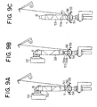
- the ascent of the tail yarn cutting member 51 is regulated by a regulating means, and as shown in Fig. 9B of the present application, the tail yarn cutting member 51 detached from the cop 53 descends to a position where it abuts the spindle base portion 54. Then, the yarn Y connected from the cop 53 to the traveler 56 of the ring rail 55 is grasped between the tail yarn cutting member 51 and the spindle base portion 54, and the cop 53 further ascends, whereby the yarn Y is cut by the cutter portion 51b.
- the angle at which the yarn Y forming an oblique winding 53a is wound around the bobbin i. e. , the angle thereof with respect to the horizontal plane
- the method according to JP 2002-173837 A is executed in a state in which the above-mentioned winding angle is small, it can occur that the yarn Y connected from the cop 53 to the grasping portion is wound around the bobbin fitting portion 51a and the spindle during the further ascent of the cop 53 from the state in which the yarn Y is grasped between the tail yarn cutting member 51 and the spindle base portion 54.
- the yarn Y is not cut by the cutter portion 51b but is torn off, with the result that the cut yarn end is larger than in the case in which the yarn is cut by the cutter portion 51b.
- the cut yarn end becomes longer, the requisite power consumption for rotating the spindle at the time of taking up increases, and also scattering of waste cotton occurs.
- the diameter of the cutter portion 51b is increased, the yarn Y can be cut at a position where it abuts the cutter portion 51b. However, this involves an increase in the power consumption during take-up operation.
- the present invention has been made in view of the above problem in the prior art. It is an object of the present invention to provide a method of cutting yarn during doffing in a spinning machine which makes it possible to effect yarn cutting so as to attain a short yarn end even in a case in which the yarn is of low count and the cop diameter is large.
- a method of cutting yarn during doffing includes the steps of: grasping yarn connected from a traveler to the cop by a spindle base portion and a grasping member after forming an oblique winding on the cop during suspension for doffing, the grasping member being fitted onto the spindle base portion so as to be capable of ascending and descending; grasping the cop by the doffing device; rotating the spindle in a state in which the spindle is capable of relative rotation with respect to the cop to thereby attain a state in which the oblique winding formed on the cop extends straight from a top portion of the cop to a grasping position where grasping by the grasping member is effected; and raising the cop further by the doffing device to cut the yarn.
- the yarn connected from the traveler to the cop is grasped between the spindle base portion and the grasping member fitted onto the spindle base portion so as to be capable of ascending and descending with respect to the spindle base portion.
- the cop is grasped by the doffing device and the spindle is rotated in a state in which it is capable of relative rotation with respect to the cop, thereby attaining a state in which the oblique winding formed on the cop extends straight from the top portion of the cop to the position where the grasping by the grasping member is effected.
- the cop is further raised by the doffing device to cut the yarn.
- the winding angle of the yarn forming the oblique winding with respect to the bobbin i.e., the angle thereof with respect to the horizontal plane
- the yarn is not cut at a position corresponding to a cutter portion or edge portion if there is any, but is torn off above the cutter portion or edge portion, resulting in a rather long yarn end.
- the yarn connected from the traveler to the cop is grasped by the grasping member, and the cop is raised after the oblique winding is changed so as to extend straight, so that a state is attained in which the yarn abuts the cutter portion or the edge portion at a large angle, and the yarn is cut by the cutter portion or the edge portion.
- the yarn is of low count and the cop has a large diameter, it is possible to effect cutting so as to attain a short yarn end.
- the grasping member includes a bobbin fitting portion onto which a bobbin is fitted and a tail yarn cutting member equipped with a cutter portion provided below the bobbin fitting portion, the tail yarn cutting member being capable of ascending and descending along a blade extending upwardly from the spindle base portion and capable of grasping between the tail yarn cutting member and the spindle base portion the yarn connected from the traveler to the cop, and the method further includes the steps of: stopping a ring rail in a state in which, during suspension for doffing, yarn connected to the cop by way of the traveler passes a position below a contact portion where the tail yarn cutting member and the spindle base portion are in contact with each other; stopping the spindle in a state in which a roll or less of yarn is wound at a position below the contact portion where the tail yarn cutting member and the spindle base portion are in contact with each other; pulling up the cop by the doffing device after moving a lappet to a retracted position; raising the tail yarn cutting member together
- the grasping member a tail yarn cutting member equipped with a bobbin fitting portion onto which a bobbin is fitted and a cutter portion provided below the bobbin fitting portion.
- the spindle is stopped, with one or less roll of yarn wound at a position not higher than the contact portion where the tail yarn cutting member and the spindle base portion are in contact with each other.
- the lappet is moved to the retracted position, and then the cop is pulled up by the doffing device, so that the yarn connected from the cop to the traveler is guided, halfway through the pulling up, to a position between the tail yarn cutting member and the spindle base portion.
- the ascent of the tail yarn cutting member is regulated by the regulating means, the tail yarn cutting member is detached from the cop and descends, and the yarn is grasped between the tail yarn cutting member detached from the cop and the spindle base portion.
- the spindle is rotated, and a state is attained in which the oblique winding formed on the cop extends straight from the top portion of the cop to the position where the grasping by the grasping member is effected, and then the cop is further raised by the doffing device to cause the yarn to be reliably cut by the cutter portion.
- the method further includes the steps of: straightening yarn that is connected from the lappet to the traveler while wound around the spindle, by returning the lappet to a spinning position after pulling up the cop from the spindle by the doffing device; and moving the lappet again to the retracted position to fit the empty bobbin onto the spindle.
- the lappet is returned to the spinning position, whereby the winding of the yarn is canceled. Then, the empty bobbin is fitted onto the spindle, with the lappet being again arranged at the retracted position where it does not interfere with the doffing.
- the method further includes the step of: fitting the empty bobbin onto the spindle in a state in which the yarn connected from the lappet to the traveler while wound around the spindle has been moved to a position where the yarn is not caught by the bobbin, by raising the ring rail after pulling up the cop from the spindle by the doffing device.
- the ring rail is raised in a state in which the cop is doffed and prior to the fitting of the empty bobbin onto the spindle, whereby the yarn extending from the lappet to the traveler is moved, while being wound around the spindle, to a position where the yarn is not caught by the bobbin at the time of the fitting of the empty bobbin onto the spindle. In this state, the emptybobbin is fitted onto the spindle.
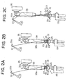
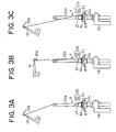
- Figs. 1A and 1B, 2A through 2C, and 3A through 3C are schematic side views illustrating the operation at the time of doffing;
- Fig. 4 is a schematic diagram showing a construction of a ring spinning machine;
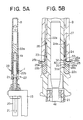
- Fig. 5A is a schematic side view, partly in section, of a spindle;
- Fig. 5B is a sectional view showing how a tail yarn cutting member is mounted;
- Fig. 6 is a schematic perspective view of the tail yarn cutting member and a spindle base portion;
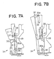
- Figs. 7A and 7B are schematic diagrams showing the relationship between the spinning machine and a doffing device.
- a lifting drive system, a draft part, and a spindle drive system are independently drive-controlled.
- a rotation shaft 2 of a front roller 1 constituting the draft part is rotated through a row of gears (not shown) arranged between the rotation shaft 2 and a driving shaft 3 rotated by a main motor M.
- a spindle 4 is rotated through a spindle tape (not shown) stretched between the spindle 4 and a tin pulley 5 fixed to the driving shaft 3.
- the RPM ratio between the front roller 1 and the spindle 4 is set in correspondence with the spinning condition (the number of twists).
- the main motor M a variable-speed motor driven through an inverter 6 is used.
- a sensor S1 In the vicinity of a gear 2a fixed to the rotation shaft 2 so as to be capable of integral rotation, there is arranged a sensor S1 adapted to output pulse signals in correspondence with the rotation of the front roller 1.
- the lifting device causes a ring rail 8 and a lappet angle 9 to ascend and descend through a line shaft 7.
- a lappet 10 mounted to the lappet angle 9 is a lappet 10 equipped with a snail wire 10a, and yarn Y sent out from the front roller 1 is guided to a traveler 11, which is slidable on a ring 8a, by way of the snail wire 10a.
- the lifting device is basically of the same construction as the device disclosed in JP 7-300728 A.
- the line shaft 7 is arranged along the longitudinal direction of a machine frame of the spinning machine, and screw gears 12 (only one of which is shown in Fig. 4), arranged at predetermined intervals, are fitted into the line shaft so as to be capable of integral rotation.
- the ring rail 8 is supported by a plurality of porker pillars 13 (only one of which is shown in Fig. 4).
- the porker pillars 13 are supported on the machine frame (not shown) so as to be vertically movable and have screw portions 13a in the lower portions thereof. Each screw portion 13a is threadedly engaged with a nut member 14 rotatably supported at a predetermined height position on the machine frame.
- each nut member 14 there are integrally formed screw gears (not shown) in mesh with the screw gears 12.
- the lappet angle 9 can also be caused to ascend and descend in synchronism with the ring rail 8 by a similar ascent/descent mechanism.
- the line shaft 7 is connected to the drive shaft of a servo motor 15 through a row of gears (not shown), and its rotating speed and rotating direction can be freely changed.
- the servo motor 15 is drive-controlled by a control device 16 through a servo driver 17.
- the servo motor 15 is equipped with a rotary encoder 18.
- the spindle 4 is rotatably supported by a bolster 20 fixed to a spindle rail 19, through the intermediation of a bearing 21.
- the spindle 4 is equipped with a blade portion 22 and a spindle shaft 4a firmly attached to the lower central portion of the blade portion 22, and the spindle shaft 4a is rotatably supported by the bolster 20.
- the blade portion 22 is formed of aluminum or an aluminum alloy except for a spindle base portion 22b, and the spindle base portion 22b, which is formed of resin, is fitted into the lower portion of a blade 22a.
- the spindle shaft 4a is insert-molded in the blade portion 22, which is formed of aluminum or an aluminum alloy.
- a tail yarn cutting member 23 serving as a grasping member which is capable of ascending and descending.
- the tail yarn cutting member 23 is equipped with a bobbin fitting portion 24 onto which a bobbin B is fitted and a cutter portion 25 provided below the bobbin fitting portion 24.
- the cutter portion 25 includes a separate annular cutter member 25a and is equipped with a plurality of lock protrusions 25b for fixing the cutter member 25a.
- the diameter of the forward end portion of the cutter member 25a is larger than the outer diameter of the lower end portion of the bobbin B.
- the bobbin fitting portion 24 is formed in a cylindrical configuration, and has on its inner side a recess 24a for accommodating a coil spring 26.
- the lower end portion of the tail yarn cutting member 23 is kept in contact with the spindle base portion 22b, making it possible to grasp tail yarn between the tail yarn cutting member 23 and the spindle base portion 22b.
- a collar 27 serving as a stopper is fixed to the blade 22a at a position where its lower portion is opposed to the upper end of the bobbin fitting portion 24 in a state in which the tail yarn cutting member 23 is in contact with the spindle base portion 22b.
- the outer diameter of the collar 27 is somewhat smaller than the inner diameter of the recess 24a, and the tail yarn cutting member 23 slides along the collar 27.
- the bobbin fitting portion 24 is formed such that its outer diameter gradually decreases toward its upper end.
- the coil spring 26 is accommodated in the recess 24a, with its lower end abutting the lower end of the recess 24a and its upper end abutting the lower end of the collar 27.
- the coil spring 26 constitutes a spring for constantly urging the tail yarn cutting member 23 toward the spindle base portion 22b. Further, the coil spring 26 is provided between the tail yarn cutting member 23 and the blade 22a and constitutes a regulating means adapted to prohibit, at the time of doffing, the ascent of the tail yarn cutting member 23 beyond the position where the tail yarn cutting member 23 is in contact with the spindle base portion 22b by a predetermined height or more.
- a plurality of radially extending protrusions 28a and 28b and recesses 29a and 29b that can be engaged with each other.
- the lower end portion of the tail yarn cutting member 23 and the upper end portion of the spindle base portion 22b are equipped with a plurality of teeth in mesh with each other. It is desirable that the height of the protrusions 28a and 28b and the depth of the recesses 29a and 29b be approximately 2 mm.
- the lower end portion of the tail yarn cutting member 23 is formed so as to constitute a part of the slope of an imaginary cone whose rotation center is the spindle 4 and whose apex is situated above a plane including the outer periphery of the above-mentioned lower end portion and perpendicular to the spindle 4.
- the upper end portion of the spindle base portion 22 is also formed so as to constitute a part of the slope of an imaginary cone whose rotation center is the spindle 4 and whose apex is situated above a plane including the outer periphery of the above-mentioned lower end portion and perpendicular to the spindle 4.
- End surfaces 30 on the blade 22a side of the protrusions 28b of the spindle base portion 22b are formed so as to be curved surfaces constituting the slope of a downwardly facing imaginary cone whose rotation center is the spindle 4.
- a wall 31 capable of abutting the end surfaces 30 and having a curved surface 31a forming the slope of an imaginary cone whose rotation center is the spindle.
- the end surfaces 30 and the wall 31 constitute an aligning means for securing coaxiality of the tail yarn cutting member 23 with respect to the spindle base portion 22b.
- an annular groove 32 In the lower outer peripheral surface of the bobbin fitting portion 24, there is formed an annular groove 32, in which a rubber ring 33 is accommodated so as to partially protrude from the groove 32.
- the rubber ring 33 constitutes a fitting force enhancing means for enhancing the force with which the bobbin fitting portion 24 and the bobbin B are connected together by fitting.
- the ring spinning machine is equipped with a well-known overall type doffing device (bobbin replacing device) 34.
- the doffing device 34 is equipped with a doffing bar 35 equipped with a bobbin grasping device 35a, replacing an empty bobbin E on a peg 36a of a feeding device 36 arranged below the spindle rail 19 and cop 38 on the spindle 4.
- the bobbin grasping device 35a provided on the doffing bar 35 moves along the line indicated by the arrow, fitting the empty bobbin E pulled up from the peg 36a onto an intermediate peg 37.
- the bobbin grasping device 35a moves to a position corresponding to the top of the cop 38 on the spindle 4, and after grasping the cop 38, moves along the line indicated by the arrow in Fig. 7B, pulls up the cop 38 on the spindle 4, and then fits it onto the peg 36a of the feeding device 36.
- the bobbin grasping device 35a moves again along the line indicated by the arrow in Fig. 7A, and fits the empty bobbin E on the intermediate peg 37 onto the spindle 4 before moving along the line indicated by the arrow in Fig. 7B to be returned to the standby position above the peg 36a.
- the control device 16 is equipped with a CPU (central processing unit) 39, a program memory 40, an operation memory 41, and an input device 42.
- the CPU 39 operates based on predetermined program data stored in the program memory 40, and controls themainmotorMandthe servomotor 15 through an interface and drive circuit (not shown).
- the program memory 40 consists of read only memory (ROM), which stores the above-mentioned program data and various items of data necessary for the execution thereof.
- the program data includes a control program for controlling the main motor M and the servo motor 15 during take-up operation, a control program for controlling the doffing device during doffing operation (bobbin replacement operation) after doffing stop, and a control program for controlling the main motor M.
- the various items of data include spinning conditions, such as the count of the yarn to be spun and the spindle RPM during spinning operation, and data corresponding to the number of times that chasing of the ring rail 8 is effected until a full bobbin state is attained.
- the operation memory 41 consists of memory allowing reading and rewriting (RAM), and temporarily stores data input by the input device 42, computation results obtained by the CPU 39, etc.
- the operation memory 41 is equipped with a backup power source (not shown).
- the input device 42 is used to input spinning condition data, such as the count of the yarn to be spun, the spindle RPM during spinning operation, the spinning length, the lift length, and the chase length.
- the CPU 39 is connected to the sensor S1 and the rotary encoder 18 through an interface.
- the CPU 39 calculates the spinning amount based on an output signal from the sensor S1.
- the CPU 39 recognizes the moving direction and position of the ring rail 8 based on an output signal from the rotary encoder 18, and based on the values thereof, controls the servo motor 15 such that the ring rail 8 performs predetermined ascending and descending motions corresponding to the spinning conditions.
- the CPU 39 recognizes, based on a signal from the doffing device 34, the stage of the doffing operation.
- the yarn Y connected from the cop 38 to the traveler 11 is grasped by the tail yarn cutting member 23 and the spindle base portion 22b, and then the spindle 4 is rotated at low speed by a predetermined amount.
- the ascertaining of the grasping of the yarn Y by the tail yarn cutting member 23 is effected based on a signal from the rotary encoder 18 corresponding to a predetermined position during doffing rise of the doffing device 34previouslyobtainedbyexperiment. Further, thepredetermined amount by which the spindle 4 is rotated at low speed is previously obtained by experiment in correspondence with the spinning conditions.
- the spinning condition data such as the count of the yarn to be spun, the spindle RPM during spinning operation, the spinning length, the lift length, and the chase length
- the bobbin B is attached to the spindle 4 so as to be capable of integral rotation in a state in which the lower portion of the bobbin B is fitted onto the bobbin fitting portion 24 of the tail yarn cutting member 23, with its upper portion being engaged with a lock member.
- the control device 16 drive-controls the servo motor 15 in synchronism with the main motor M in accordance with the spinning conditions input by the input device 42 and stored in the operation memory 41.
- the servo motor 15 is driven, the line shaft 7 is rotated through the row of gears, and the ring rail 8, the lappet angle 9, etc. are caused to ascend or descend. Further, the yarn Y sent out from the front roller 1 is taken up on the bobbin B by way of the snail wire 10a and the traveler 11.
- a full-bobbin-stop time is reached, a top bunch winding is formed, and then the ring rail 8 is abruptly lowered to form an oblique winding (barrel winding) 38a on the cop (full bobbin) 38 attached to the spindle 4. Thereafter, the ring rail 8 is stopped in a state in which the yarn Y connected to the cop 38 by way of the traveler 11 passes a position below the contact portion where the tail yarn cutting member 23 and the spindle base portion 22b are in contact with each other.
- braking is effected to stop the spindle 4 so as to attain a state in which approximately one roll of yarn is wound at a position somewhat below the contact portion where the tail yarn cutting member 23 and the spindle base portion 22b are in contact with each other, thereby attaining the state as shown in Fig. 1B.
- the lappet 10 is arranged at a retracted position where it does not interfere with doffing, and then the cop (full bobbin) 38 is pulled up by the doffing device 34.
- the tail yarn cutting member 23 is raised together with the cop 38 halfway through the pulling up, and the yarn Y connected from the cop 38 to the traveler 11 is guided to a position between the tail yarn cutting member 23 and the spindle base portion 22b.
- the yarn Y wound around the spindle base portion 22b moves along the outer surface of the blade 22a.
- the tail yarn cutting member 23 rising together with the cop 38 reaches a predetermined height, the tail yarn cutting member 23 is detached from the cop 38 by the urging force of the coil spring 26.
- the tail yarn cutting member 23 is lowered to the position where it abuts the spindle base portion 22b, and the yarn Y connected from the cop 38 to the traveler 11 is grasped between the tail yarn cutting member 23 and the spindle base portion 22b.
- the spindle 4 is rotated in a state in which it is capable of relative rotation with respect to the cop 38 grasped by the doffing device 34.
- the cop 38 is further raised by the doffing device 34, and a state is attained in which the yarn Y abuts the cutter portion 25 at a large angle close to 90 degrees, and the yarn Y is reliably cut by the cutter portion 25. Further, the operation of the doffing device 34 is continued and the cop 38 undergoes doffing until the state as shown in Fig. 3A is attained.
- the lappet 10 is returned to the spinning position, whereby the winding of the yarn Y around the spindle 4 is canceled.
- the lappet 10 is reversed to the retracted position again, and as shown in Fig. 3C, a state is attained in which the yarn Y extending to the traveler 11 by way of the lappet 10 is straight. Thereafter, an empty bobbin is fitted onto the spindle 4.
- the winding angle of the yarn Y forming the oblique winding 38a with respect to the bobbin B (the angle thereof with respect to the horizontal plane) is small, so that, when the cop 38 is raised as it is, the portion of the yarn Y below the oblique winding 38a may be wound around the spindle 4.
- the cop 38 is pulled up in this state, the yarn Y is not cut by the cutter portion 25 despite the presence of the cutter portion 25 but torn off above the cutter portion 25, resulting in a long yarn end.
- the cop 38 is not raised as it is from the position shown in Fig. 2B but raised after a change to cause the oblique winding 38a to extend straight, so that the yarn Y abuts the cutter portion 25 at a large angle, whereby the yarn Y is cut reliably by the cutter portion 25.
- the end portion of the yarn Y connected to the traveler 11 is grasped between the tail yarn cutting member 23 and the spindle base portion 22b until the next doffing.
- the tail yarn grasped between the tail yarn cutting member 23 and the spindle base portion 22b is connected to the cop 38 at the time of the next doffing and is detached from the spindle 4.
- the yarn Y abuts the cutter portion 25 at a large angle (an angle close to 90 degrees) , and the yarn Y is cut by the cutter portion 25. Further, since the cop 38 is not rotated, it is possible to prevent the yarn Y extending from the snail wire 10a to the traveler 11 from being wound around the spindle 4, and there is no need to perform the operation of moving the lappet 10 to the retracted position again after the lappet 10 is arranged at the spinning position prior to the fitting of the empty bobbin.
- the yarn Y connected from the lappet 10 to the traveler 11 while wound around the spindle 4 is moved to a position where it is not grasped between the bobbin B and the spindle 4 at the time of fitting the empty bobbin onto the spindle 4.
- the lappet 10 is moved to the spinning position from the retracted position, and arranged at the spinning position again, the empty bobbin being fitted after straightening the yarn Y connected from the lappet 10 to the traveler 11, there is no fear of the yarn Y being caught between the empty bobbin and the spindle 4 when the empty bobbin is fitted onto the spindle 4.
- the construction of the tail yarn cutting member 23 is not restricted to the one in which the protrusions 28a and the recesses 29a are formed on the surface thereof opposed to the spindle base portion 22b. Further, the construction of the cutter portion 25 is not restricted to the one in which the edge member 25a is a separate component. For example, as shown in Fig. 8, it is also possible to integrally form, as the tail yarn cutting member 23, a disc-like edge portion 24b at the lower end of the bobbin fitting portion 24. The outer configuration of the edge portion 24b is not restricted to the circular one; it may also be of a saw-tooth-like configuration.
- a magnet as an urging means for urging the tail yarn cutting member 23 toward the spindle base portion 22b in the state in which the tail yarn cutting member 23 and the spindle base portion 22b are in contact with each other.
- a magnet is embedded in the upper surface of the spindle base portion 22b, and a magnetic material (e.g., iron) is fixed to the lower surface of the bottom portion of the tail yarn cutting member 23.
- a magnet on either side of the spindle base portion 22b and the tail yarn cutting member 23, or provide a magnet on the tail yarn cutting member 23 side and a magnetic material on the spindle base portion 22b side.
- a retaining ring or a pin as a stopper is fixed to a predetermined position on the blade 22a as a regulating means for regulating the ascent of the tail yarn cutting member 23.
- the tail yarn cutting member 23 abuts the retaining ring or the pin during its ascent together with the cop 38, whereby it is detached from the cop 38.
- the end surfaces of the protrusions 28a and 28b and the bottom surfaces of the recesses 29a and 29b are not necessarily inclined outwardly and downwardly; they may also be horizontal. However, when a force to pull out the grasped yarn Y is applied, the resistance to the pulling-out of the yarn is larger in the case of the downwardly inclined configuration, making it harder for the yarn to be pulled out.
- the fitting force enhancing means is not restricted to the rubber ring 33; it may also be a plate-like or linear spring material.
- the spring material is not restricted to a completely ring-like one; it is also possible to adopt a spring in the form of a partially cut-out ring. Further, it is also possible to accommodate a spring member in a recess formed in the outer surface of the bobbin fitting portion 24 such that its arcuate portion protrudes. It is also possible to provide a button urged by a spring.
- the outer diameter of the cutter portion 25 may be smaller than the outer diameter of the bottom portion of the bobbin B. In this case, there is no fear of the yarn Y connected from the cop 38 to the traveler 11 during doffing being cut before being grasped between the tail yarn cutting member 23 and the spindle base portion 22b.
- the construction of the grasping member capable of grasping the yarn Y connected from the traveler 11 to the cop 38 in cooperation with the spindle base portion 22b during doffing is not restricted to the one which, as in the case of the tail yarn cutting member 23, descends to grasp the yarn Y after having risen integrally with the cop 38.
- the cutter portion 25 it is also possible to provide an edge portion, causing the yarn Y to abut the edge portion during the doffing of the cop 38 to be torn off.
- the driving system for the spindle 4 it is possible to adopt, instead of the construction in which the spindle is driven by the spindle tape wrapped around the tin pulley 5, a construction in which the spindle 4 is driven by a tangential belt. Further, it is also possible to adopt a so-called single-spindle drive system in which a motor is provided for each spindle.
- the present invention is applicable not only to a ring spinning machine, but also to a ring twisting machine.
Landscapes
- Engineering & Computer Science (AREA)
- Mechanical Engineering (AREA)
- Textile Engineering (AREA)
- Spinning Or Twisting Of Yarns (AREA)
Abstract
Description
Claims (6)
- Amethod of cutting yarn during doffing in a spinning machine in which yarn is automatically taken up when re-starting the machine after an empty bobbin is fitted onto a spindle from which cop has been pulled up by a doffing device, the method comprising the steps of:grasping yarn connected from a traveler to the cop by a spindle base portion and a graspingmember after forming an oblique winding on the cop during suspension for doffing, the grasping member being fitted onto the spindle base portion so as to be capable of ascending and descending;grasping the cop by the doffing device;rotating the spindle in a state in which the spindle is capable of relative rotation with respect to the cop to thereby attain a state in which the oblique winding formed on the cop extends straight from a top portion of the cop to a grasping position where grasping by the grasping member is effected; andraising the cop further by the doffing device to cut the yarn.
- A method according to Claim 1, wherein the grasping member includes a bobbin fitting portion onto which a bobbin is fitted and a tail yarn cutting member equipped with a cutter portion provided below the bobbin fitting portion, the tail yarn cutting member being capable of ascending and descending along a blade extending upwardly from the spindle base portion and capable of grasping between the tail yarn cutting member and the spindle base portion the yarn connected from the traveler to the cop, the method further comprising the steps of:stopping a ring rail in a state in which, during suspension for doffing, yarn connected to the cop by way of the traveler passes a position below a contact portion where the tail yarn cutting member and the spindle base portion are in contact with each other;stopping the spindle in a state in which a roll or less of yarn is wound at a position below the contact portion where the tail yarn cutting member and the spindle base portion are in contact with each other;pulling up the cop by the doffing device after moving a lappet to a retracted position;raising the tail yarn cutting member together with the cop halfway through the pulling up of the cop;guiding the yarn connected from the cop to the traveler to a position between the tail yarn cutting member and the spindle base portion; andgrasping the yarn between the tail yarn cutting member, which is detached from the cop by regulating ascent of the tail yarn cutting member with a regulating means, and the spindle base portion.
- A method according to Claim 2, further comprising the steps of:straightening yarn that is connected from the lappet to the traveler while wound around the spindle, by returning the lappet to a spinning position after pulling up the cop from the spindle by the doffing device; andmoving the lappet again to the retracted position to fit the empty bobbin onto the spindle.
- A method according to Claim 2, further comprising the step of fitting the empty bobbin onto the spindle in a state in which the yarn connected from the lappet to the traveler while wound around the spindle has been moved to a position where the yarn is not caught by the bobbin, by raising the ring rail after pulling up the cop from the spindle with the doffing device.
- A method according to Claim 1, further comprising the step of rotating the spindle by a predetermined amount, with the spindle being capable of relative rotation with respect to the cop.
- A method according to Claim 2, wherein the tail yarn cutting member is urged toward the spindle base portion.
Applications Claiming Priority (2)
| Application Number | Priority Date | Filing Date | Title |
|---|---|---|---|
| JP2003134871 | 2003-05-13 | ||
| JP2003134871A JP4001052B2 (en) | 2003-05-13 | 2003-05-13 | Yarn cutting method during doffing in a spinning machine |
Publications (3)
| Publication Number | Publication Date |
|---|---|
| EP1477596A2 true EP1477596A2 (en) | 2004-11-17 |
| EP1477596A3 EP1477596A3 (en) | 2005-11-09 |
| EP1477596B1 EP1477596B1 (en) | 2008-12-17 |
Family
ID=33028349
Family Applications (1)
| Application Number | Title | Priority Date | Filing Date |
|---|---|---|---|
| EP20040009105 Expired - Lifetime EP1477596B1 (en) | 2003-05-13 | 2004-04-16 | Method of cutting yarn during doffing in spinning machine |
Country Status (4)
| Country | Link |
|---|---|
| EP (1) | EP1477596B1 (en) |
| JP (1) | JP4001052B2 (en) |
| CN (1) | CN100335696C (en) |
| DE (1) | DE602004018422D1 (en) |
Cited By (1)
| Publication number | Priority date | Publication date | Assignee | Title |
|---|---|---|---|---|
| CN113604915A (en) * | 2021-07-07 | 2021-11-05 | 湖北天门纺织机械股份有限公司 | Adjusting system for doffing and yarn breaking of spinning frame and optimization method thereof |
Families Citing this family (4)
| Publication number | Priority date | Publication date | Assignee | Title |
|---|---|---|---|---|
| JP2007284823A (en) * | 2006-04-17 | 2007-11-01 | Toyota Industries Corp | Method for cutting off remaining yarn in spinning machine |
| CN106904491B (en) * | 2017-03-17 | 2023-03-31 | 杭州锐冠科技有限公司 | Wire plugging device |
| EP3748054B1 (en) * | 2019-06-06 | 2023-02-22 | Lakshmi Machine Works Ltd. | Ring spinning machine comprising a lappet tilting apparatus and an automatic yarn piecing assembly |
| CN111441112B (en) * | 2020-05-09 | 2024-12-03 | 浙江日发纺机技术有限公司 | Spinning device and automatic yarn dropping and yarn feeding method thereof |
Family Cites Families (4)
| Publication number | Priority date | Publication date | Assignee | Title |
|---|---|---|---|---|
| JPS5720613Y2 (en) * | 1973-12-27 | 1982-05-04 | ||
| IT1208008B (en) * | 1987-02-13 | 1989-06-01 | Savio Spa | MIXTURE COMPOSITIONS WITH WATER ABASE OF A HYDROPHILIC CATIONIC POLYMEO AND ANIONIC TENSION-ACTIVE AGENT, AND USEFUL AS FLOCCULATING AGENTS |
| DE19537687A1 (en) * | 1995-10-11 | 1997-04-17 | Spindelfabrik Hartha Gmbh | Precise yarn cutter at a spinning or twisting machine spindle |
| JP4284863B2 (en) * | 2000-12-07 | 2009-06-24 | 株式会社豊田自動織機 | Bottom thread cutting method and bottom thread cutting device in spinning machine |
-
2003
- 2003-05-13 JP JP2003134871A patent/JP4001052B2/en not_active Expired - Fee Related
-
2004
- 2004-04-16 DE DE200460018422 patent/DE602004018422D1/en not_active Expired - Lifetime
- 2004-04-16 EP EP20040009105 patent/EP1477596B1/en not_active Expired - Lifetime
- 2004-05-12 CN CNB2004100445904A patent/CN100335696C/en not_active Expired - Fee Related
Cited By (1)
| Publication number | Priority date | Publication date | Assignee | Title |
|---|---|---|---|---|
| CN113604915A (en) * | 2021-07-07 | 2021-11-05 | 湖北天门纺织机械股份有限公司 | Adjusting system for doffing and yarn breaking of spinning frame and optimization method thereof |
Also Published As
| Publication number | Publication date |
|---|---|
| DE602004018422D1 (en) | 2009-01-29 |
| EP1477596A3 (en) | 2005-11-09 |
| JP2004339621A (en) | 2004-12-02 |
| JP4001052B2 (en) | 2007-10-31 |
| CN1550585A (en) | 2004-12-01 |
| CN100335696C (en) | 2007-09-05 |
| EP1477596B1 (en) | 2008-12-17 |
Similar Documents
| Publication | Publication Date | Title |
|---|---|---|
| EP1477595A2 (en) | Method of operating ring spinning machine during suspension for doffing and method of cutting yarn during doffing | |
| EP1477596B1 (en) | Method of cutting yarn during doffing in spinning machine | |
| CN101319418B (en) | Method and appratus for controlling roving machine | |
| EP1477597B1 (en) | Tail yarn cutting device for spinning machine | |
| JP4284863B2 (en) | Bottom thread cutting method and bottom thread cutting device in spinning machine | |
| JP2005336662A (en) | Method for removing residual thread in loom | |
| JP2007284823A (en) | Method for cutting off remaining yarn in spinning machine | |
| EP0953661B1 (en) | Method of forming cop for spinning machine | |
| JP2000303270A (en) | Spinning machine winding operation control device | |
| JP3136989B2 (en) | Method for preventing breakage of yarn at startup of spinning machine and drive control device for spinning machine | |
| JP2004346445A (en) | Operation method in stopping of doffing in spinning machine and yarn cutting method in doffing | |
| JPH11152630A (en) | Yarn cutting in fine spinning frame | |
| JP2001279538A (en) | Spinning machines such as ring spinning machines | |
| JPS63182421A (en) | Method for stopping operation of spinning frame | |
| JP3136990B2 (en) | Ring rail lifting and lowering method at start of spinning machine and ring rail lifting and lowering control device | |
| JP3480125B2 (en) | Spinning machine operation method and drive control device | |
| JPH083824A (en) | Stopping of spinning machine and stopping-controlling apparatus | |
| JP2001316948A (en) | Method for stopping ring spinning loom and ring spinning loom | |
| JPH07310242A (en) | Method for shutdown in spinning machine and shutdown control unit | |
| JPH0835129A (en) | Method of forming cop with stretching and twisting frame | |
| JP2924165B2 (en) | Automatic roving method of roving in roving machine | |
| JP2002266176A (en) | Stopping method and stopping controlling apparatus in spinning machine | |
| JPH09302535A (en) | Winding of tail yarn in spinning machinery and controller for lifting and lowering of ring rail | |
| JPH0748682Y2 (en) | Rover bobbin tail cutting device | |
| JP3003295B2 (en) | Method to prevent shoulder collapse of formed roving winding in roving machine |
Legal Events
| Date | Code | Title | Description |
|---|---|---|---|
| PUAI | Public reference made under article 153(3) epc to a published international application that has entered the european phase |
Free format text: ORIGINAL CODE: 0009012 |
|
| AK | Designated contracting states |
Kind code of ref document: A2 Designated state(s): AT BE BG CH CY CZ DE DK EE ES FI FR GB GR HU IE IT LI LU MC NL PL PT RO SE SI SK TR |
|
| AX | Request for extension of the european patent |
Extension state: AL HR LT LV MK |
|
| PUAL | Search report despatched |
Free format text: ORIGINAL CODE: 0009013 |
|
| AK | Designated contracting states |
Kind code of ref document: A3 Designated state(s): AT BE BG CH CY CZ DE DK EE ES FI FR GB GR HU IE IT LI LU MC NL PL PT RO SE SI SK TR |
|
| AX | Request for extension of the european patent |
Extension state: AL HR LT LV MK |
|
| 17P | Request for examination filed |
Effective date: 20051121 |
|
| AKX | Designation fees paid |
Designated state(s): CH DE IT LI |
|
| GRAP | Despatch of communication of intention to grant a patent |
Free format text: ORIGINAL CODE: EPIDOSNIGR1 |
|
| GRAS | Grant fee paid |
Free format text: ORIGINAL CODE: EPIDOSNIGR3 |
|
| GRAA | (expected) grant |
Free format text: ORIGINAL CODE: 0009210 |
|
| AK | Designated contracting states |
Kind code of ref document: B1 Designated state(s): CH DE IT LI |
|
| REG | Reference to a national code |
Ref country code: CH Ref legal event code: EP |
|
| REG | Reference to a national code |
Ref country code: CH Ref legal event code: NV Representative=s name: NOVAGRAAF INTERNATIONAL SA |
|
| REF | Corresponds to: |
Ref document number: 602004018422 Country of ref document: DE Date of ref document: 20090129 Kind code of ref document: P |
|
| PLBE | No opposition filed within time limit |
Free format text: ORIGINAL CODE: 0009261 |
|
| STAA | Information on the status of an ep patent application or granted ep patent |
Free format text: STATUS: NO OPPOSITION FILED WITHIN TIME LIMIT |
|
| 26N | No opposition filed |
Effective date: 20090918 |
|
| REG | Reference to a national code |
Ref country code: CH Ref legal event code: PL |
|
| PG25 | Lapsed in a contracting state [announced via postgrant information from national office to epo] |
Ref country code: LI Free format text: LAPSE BECAUSE OF NON-PAYMENT OF DUE FEES Effective date: 20090430 Ref country code: CH Free format text: LAPSE BECAUSE OF NON-PAYMENT OF DUE FEES Effective date: 20090430 |
|
| PG25 | Lapsed in a contracting state [announced via postgrant information from national office to epo] |
Ref country code: IT Free format text: LAPSE BECAUSE OF NON-PAYMENT OF DUE FEES Effective date: 20090416 |
|
| REG | Reference to a national code |
Ref country code: DE Ref legal event code: R084 Ref document number: 602004018422 Country of ref document: DE |
|
| PGFP | Annual fee paid to national office [announced via postgrant information from national office to epo] |
Ref country code: DE Payment date: 20170411 Year of fee payment: 14 |
|
| REG | Reference to a national code |
Ref country code: DE Ref legal event code: R119 Ref document number: 602004018422 Country of ref document: DE |
|
| PG25 | Lapsed in a contracting state [announced via postgrant information from national office to epo] |
Ref country code: DE Free format text: LAPSE BECAUSE OF NON-PAYMENT OF DUE FEES Effective date: 20181101 |