CROSS-REFERENCE TO RELATED PATENT APPLICATIONS
The present application claims priority to U.S. provisional patent application
serial number 60/469,822, which contains subject matter related to that disclosed in U.S.
Patent Application Serial No. 10/336,991, filed January 6, 2003, entitled "Rotation
Sensor" and now issued as U.S. patent 6,715,368 B1; U.S. Patent Application Serial No.
10/316,442, filed on December 11, 2002, entitled "Rotation Sensor" and now issued as
U.S. patent 6,725,734 B1; Japanese Patent Application No. 2002-299218, filed in the
Japanese Patent Office on October 11,2002; and Japanese Patent Application No. 2002-14185,
filed in the Japanese Patent Office on January 23, 2002, the entire contents of
each of which being incorporated herein by reference.
BACKGROUND OF THE INVENTION
FIELD OF THE INVENTION
The present invention relates to rotation sensors and couplings used in rotation
sensors, where such rotation sensors may be used as an automotive rotation sensor for
steering systems. More particularly, the present invention relates to contact-type
automotive rotation sensors and couplings therefor.
DISCUSSION OF THE BACKGROUND
A general summary of the related art is provided in the two U.S. Patent
Applications cited above, and therefore is not repeated in detail. Furthermore, it is
worth noting that conventional couplings used in rotation sensors generally include
coupling mechanisms made of metal, where shifting motions in the coupling
mechanisms are absorbed by the elasticity of the coupling mechanisms themselves.
Thus, the coupling mechanisms are generally complex, 3-dimensional structures made
from a single substrate (such as a metal sheet). The complex shapes enable the coupling
to prevent relative motion in a rotational sense between a rotor and a base to be
restricted, while motion in either one dimension or another dimension of an x-y plane is
permitted. This motion in the x-y plane is accomplished by having the coupling absorb
the translational movement by compression, and extension of the resilient portions of
the coupling. Conventional couplings interconnect an inner member to an outer
member by way of "rails" formed in the coupling. A second set of rails interconnects
the outer member to a base.
A market for rotation sensors and couplings for use in a rotation sensor is the
highly competitive automotive parts industry. The manufacturing environment for
products supplied to automotive manufacturers is highly competitive in terms of product
price, size and weight, and maintainability. Furthermore, automotive manufacturers
often require "second sourcing" for automotive parts to avoid the risk inherent with
receiving parts from a sole-source provider. One limitation with being able to obtain
quality parts from a "second-source," is the compatibility of one manufacturer's
coupling for use in a general rotation sensor. For example, one coupling may be
designed in a compatible fashion with surrounding components, by accounting for
weight, moment of the second rotating plate, and friction with the surrounding
components, because the shaft and the second rotating plate are interconnected by the
elastic coupling component. However, if there is a change in the surrounding parts, the
compatibility, and ultimately the reduced reliability of the coupling or the rotation
sensor itself, may be compromised.
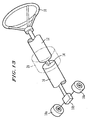
Figure 13 shows a portion of an automobile, to which the rotation sensor (and
the coupling therefore) may be mounted to a steering handle 10 that is directly coupled
to a column shaft 12. The steering shaft is coupled through a torsion bar 14 to the
column shaft 12 and on the other end is coupled to an electrically-operated power
steering mechanism 18. This power steering mechanism accommodates the rack and
pinion for steering front wheels 19 and an electric motor for assisting a steering
operation.
During the steering operation, the torsion bar 14 couples the column shaft 12
with the steering shaft 16 and receives a reactive twisting force from a road surface. As
a result, a rotational deviation occurs between the column shaft 12 and the steering shaft
16. Rotation sensors serve the general function of identifying the rotational deviation
and therefore the reaction torque that is applied to the steering shaft 16 and in turn the
steering handle 10.
SUMMARY OF THE INVENTION
An object of the present invention is to address the above-identified and other
limitations of conventional rotation sensors and couplings used in the rotation sensors.
The present inventor recognized that a problem with conventional systems is
that because they are based on integral structures, the burden of accommodating shifting
forces in the steering mechanism rests on the bending elasticity of the coupling
mechanism. However, the complexity of the coupling mechanism required to provide a
sufficiently large difference in stiffness between the angular direction and lateral
direction, results in a complex structure that is difficult to manufacture. Such a part
would also be unique to the surrounding components used with it.
The present inventor also recognized that the elasticity of the conventional
couplings needs to be a design consideration that takes into account the unique weight,
moment of the second rotating plate, and the friction with the surrounding components,
so that the shaft and the second rotating plate may be accurately coupled by way of the
coupling. However, any change in surrounding components, either for one particular
car model, or others, may compromise the operational effectiveness of the coupling,
based on the insufficient elasticity of the coupling for the modified environment in
which it is used.
In light of these problems, the present inventor recognized that a multi-component
coupling, that does not exclusively rely on elasticity, would offer benefits in
terms of simplified manufacturability, ability to operate in multiple environments with
differing surrounding parts, and is easily replaceable. Functional attributes of the
present invention as recognized by the present inventor are that the coupling is able to
transfer the angular motion of the shaft accurately to the second turntable (or plate) and
can do so without damping or delay.
Another attribute of the present invention is that by having a coupling with
separate subcomponents that cooperate with one another, it is possible to allow
sufficient tolerance against, or even absorbing, the lateral or vertical shifting motions of
the shaft or the tumbling motion of the shaft and as a result to suppress the deterioration
of the sensing function, which is present in conventional devices.
These and other objects are addressed by way of the present invention. A non-exhaustive
list of attributes of the present invention include a multi-component coupling
mechanism that includes projections, and recesses that receive the projections so that
the relative motion of the respective subcomponents, may be controlled, mainly
allowing motion in a lateral and vertical directions, but not in a relative rotational
context.
According to one aspect of the invention, a coupling includes a first coupling
member, a second coupling member, and a third coupling member being located in
between the first coupling member and the second coupling member. The third
coupling member has formed thereon a first pair of connecting elements diametrically
opposed to one another and defining a first axis, and further has formed thereon a
second pair of connecting elements diametrically opposed to one another and defining a
second axis that is substantially perpendicular to the first axis. The first coupling
member has formed thereon a third pair of connecting elements configured to conform
to the first pair of connecting elements of the third coupling member. Formed on the
second coupling member is a fourth pair of connecting elements configured to conform
to the second pair of connecting elements of the third coupling member.
Another aspect of the invention is a rotation sensor including a casting having a
coupling contained therein. The coupling includes a first coupling member, a second
coupling member, and a third coupling member being located in between the first
coupling member and the second coupling member. The third coupling member has
formed thereon a first pair of connecting elements diametrically opposed to one another
and defining a first axis, and further has formed thereon a second pair of connecting
elements diametrically opposed to one another and defining a second axis that is
substantially perpendicular to the first axis. The first coupling member has formed
thereon a third pair of connecting elements configured to conform to the first pair of
connecting elements of the third coupling member. Formed on the second coupling
member is a fourth pair of connecting elements configured to conform to the second
pair of connecting elements of the third coupling member.
In still another aspect of the invention a coupling includes a first coupling
member, a second coupling member, and a third coupling member being located in
between the first
coupling member and the second coupling member. Also included are means for
joining the first coupling member to the third coupling member, and means for joining
the second coupling member with the third coupling member.
BRIEF DESCRIPTION OF THE DRAWINGS
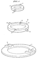
Figure 1 is a perspective view of respective subcomponents of a coupling
according to the present invention;
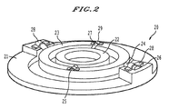
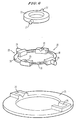
Figure 2 is the same coupling as shown in Figure 1, although the subcomponents
are placed together and held in place by elastic members which permit limited motion in
a z-direction, perpendicular to an x-y plane;
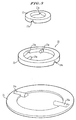
Figure 3 is a perspective view of another embodiment of the coupling according
to the present invention;
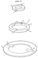
Figure 4 is another embodiment of the coupling according to the present
invention;
Figure 5 is yet another embodiment according to the present invention;
Figure 6 is another embodiment of a coupling according to the present invention;
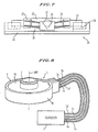
Figure 7 corresponds with the coupling in Figure 6, although is shown in an
assembled configuration;
Figure 8 is a perspective view of a rotation sensor that includes one of the
couplings embodiments of the present invention;
Figure 9 is a perspective view of another coupling, that uses an integral, single
piece construction;
Figure 10 is a cross-section of a rotation sensor according to the present
invention;
Figure 11 is a plan view of a torque sensor that includes the coupling of Figure
9;
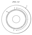
Figure 12 is a schematic plan view of a base plate of a rotation sensor according
to the present invention; and
Figure 13 shows a portion of an automobile, to which a rotation sensor can be
mounted.
DETAILED DESCRIPTION OF THE PREFERRED EMBODIMENTS
Embodiments of the present invention will now be described hereinafter in detail
with reference with the accompanying drawings. Figure 1 is a perspective view of the
respective subcomponents of a coupling 20. These subcomponents include a first
coupling ring 21, a second coupling ring 22, and a third coupling ring 23. The third
coupling ring 23 is of a ring shape (a portion of a cylinder) and includes a pair of
connecting projections 24 disposed on an outer circumferential surface of the third
coupling ring 23, at diametrically opposed positions along a first diameter. Facing an
inner portion of the third coupling ring 23, at diametrically opposed positions are v-grooves
25. The grooves 25 are positioned along a second diameter, which is
perpendicular to the first diameter. Although the grooves (v-shaped grooves) 25 are
shown as v-shaped, flat or U-shaped grooves are examples of other acceptably-shaped
grooves as well. Other shapes may be used as well, where the design consideration is to
reduce the number of contact points (or surface area) between the projections and
grooves, so as to permit motion along the second diameter, of the second ring 22 that
will fit therein. The material for the third ring 23, may be metal, plastic, epoxy resin or
other material (or combination of materials, such as Teflon coated substrates) that
provides a relatively easy material to manufacture, yet provides the rigidity and
durability associated with frequent use in an automobile environment, regardless of the
surrounding components.
The first coupling ring 21 includes a pair of v-grooves 26 formed on an upper
surface of the ring 21. The v-grooves 26 are diametrically opposed to one another on
the ring 21, and positioned so as to receive the connecting projections of the third
coupling ring 23. Moreover, the third coupling ring 23 has an outer diameter that is
shorter than the inner diameter of the first ring 21. However, the distance from one end
of a first of the projections 24 on the third ring, and outer end of the second projection
24 on the third ring 23, is such that they are received by the grooves 26. Once in the
grooves 26, the projections are free to slide along the first diameter direction. By
having the third coupling ring 23 disposed within the grooves 26, the third coupling ring
23 is free to rotate with the first ring 21 and can unilaterally shift along the first
diameter in the v-grooves 26.
The second coupling ring 22 also includes a pair of projections 27, which sit
within the v-grooves 25 of the third coupling ring 23. Thus, the second coupling ring 22
can freely rotate with the first ring 21 and the third ring 23, but is able to unilaterally
move in the v-grooves 25 along the second diameter.
Figure 2 is a diagram of an assembled coupling component 20. As can be seen,
the third ring 23 is allowed to move a limited distance along the first diameter of the
first ring 21, but is restricted in its movement in a perpendicular direction or in a
rotational direction. The movement of the third ring 23 along the first diameter is
restricted by the outer circumferential surface of the third ring 23 contacting the inner
surface of the first ring 21.
Spring plates 28 and 29 are attached (or integrally formed) to respective surfaces
of the rings on which the grooves are formed, and placed overtop of the projections that
fit into the grooves. When arranged this way, the third coupling ring 23 is able to move
in a limited range in an axial direction (z direction, relative to an x-y plane in which the
respective rings are disposed), only restrained by the elasticity of the spring plates 28
and 29. The spring plates 28 and 29 may be made of a resilient metallic material, or
another material that has some elasticity and durability, such as elastic bands or straps.
The coupling rings 21 and 22 are connected by way of the third coupling ring
23, even though the upper or lower surfaces of the coupling ring 21 and coupling ring
22 are not necessarily co-planar. Furthermore, a lateral shift between the two coupling
rings 21 and 22 is absorbed by way of a "sliding" motion of the connecting projections
24 and 27 in the v- grooves 26 and 25, respectively. As a consequence, the movement of
the respective rings need not absorb the motion by way of the elasticity of the materials
used to make the coupling mechanism. The sliding motion is possible, by using the
subcomponents that fit into one another and are held by the elastic spring plates 28 and
29.
While the v-grooves 26, are shown to be built on ridges on an otherwise planar
surface of the first ring 21, the grooves 26 may be integrally formed so as to be below
the surface of the ring 21, thereby making the upper surfaces of the rings 22 and 23
more co-planar with the upper surfaces of the ring 21. While there may be some
applications where co-planar operation is useful, there also are numerous applications
where the co-planar structure is not required.
Figure 3 shows an alternate embodiment, where the first connection ring 21
includes connecting projections 26a having a flat bottom surface formed to be co-planar
with the bottom surface of the connecting ring 21, but on an upper surface thereof
contain a ridge, which is an upper portion of a half cylinder shape. The connecting
portions 26a also projects "in-ward" from an interior circumferential surface, rather than
being disposed on an outer surface of the connecting ring 21. As a consequence, the
third ring 23 includes v-grooves 24a, formed on the bottom surface thereof that are
positioned to receive the connecting portions 26a when the third ring 23 is positioned
over top of the first ring 21. The projecting portions 26a carry the third ring 23, such
that the third ring 23 is free to move along the diameter defined by the two projecting
portions 26a. However, the motion of the third ring 23 is restricted in a direction that is
transverse to the diameter defined between the projection connecting portions 26a.
The third ring 23 also includes inwardly extending connecting portions 25a that
as are of a cylindrical shape. Because the connecting portions 25a on the third
connecting ring 23 are inwardly directed, v-grooves 27a are formed on a bottom outer
surface of the second ring 22. In this way, when the second ring 22 is placed over top
of the third ring 23, the connecting portions 25a sit within the v-grooves 27a of the
second connecting ring 22. In this way, the second connecting ring 22 is free to move
in the direction that is traverse to the first diameter defined by the connecting portions
26a on the first ring 21, but are restricted from moving along the first diameter
direction. When the three rings are placed together as previously discussed, a torque
shaft may be moved either along the first diameter defined by the connecting portions
26a or traverse to it, but not rotated relative to the other rings. As was the case with the
embodiment shown in Figure 2, elastic members such as spring plates may be placed
over top of the coupling portions so as to hold the connecting portions within the
respective v-grooves.
Figure 4 is another embodiment of the present invention. In this embodiment
the first coupling ring 21 is like that previously discussed with regard to Figure 1.
Likewise, the second coupling ring 22 is like that previously discussed with regard to
the embodiment discussed in Figure 3. However, the third coupling ring 23 includes
connecting portions 24b which are disposed on outer surface of the third coupling ring
23, at diametrically opposed positions. A second pair of connecting projections 25b are
disposed on an inner surface of the third coupling ring 23 and along a diameter that is
traverse to the diameter defined between the projection portions 24b. In this
embodiment, the connecting projections all include a sphere on an outer end portion
thereof. The sphere contacts the inclined sides of the v- grooves 26 and 27b at two
positions. By minimizing the number of contact points in the v-grooves lowers the
amount of friction thus permitting sliding action along the designated diameters. The
amount of friction can be controlled by coating the surface(s) of the sphere and/or v-groove
with a material (such as a resin, or TEFLON) with a predetermined coefficient
of friction, and/or by roughening the contact surfaces. As was the case with the
previous embodiments, elastic members such as spring plates may be placed over top of
the connecting projections 24b and 25b such that the respective rings are held together
and permit translatory motion in a z-direction (perpendicular to the x-y plane defined by
the two diameters of the connecting portions).
Figure 5 shows yet another embodiment of a connector according to the present
invention, where the third ring 23 includes only v-grooves, and no connecting
projections. V-grooves 24a are positioned to receive connecting portions 26a of first
coupling ring 21.
V-grooves 25 are formed on an upper surface of the third ring 23 so as to receive the
connecting portions 27 on the second ring 22. As with the other embodiments, the
combined structure (perhaps combined with the use of elastic members to hold the
respective projections in the grooves) may permit motion in a first diametric direction,
or a second diametric direction that is traverse to the first diametric direction, but not in
a relative (with regard to the rings) rotating direction. The elasticity of the spring
members used to hold the respective parts together will define the amount of motion
that is permitted in the z direction.
Figure 6 is yet a further embodiment where the third coupling ring 23 includes a
set of parallel spring feet 30, a pair of connecting projections 24 and a pair of v-groove
components. In this case, the parallel spring feet are configured to absorb a shift
between the first coupling ring 21 and the second coupling ring 22 along the axis that is
perpendicular to the plane in which the first ring 21 is positioned.
Figure 7 shows an assembled version of the coupling of Figure 6 with the
respective positioning of the projection portions within the v-grooves. Furthermore, the
projection portion 27 is shown to have 2 contact points within the v-groove 25. This
type of connection minimizes the amount of fixing between these parts so as to enable
free movement of the projection portion 27 in one dimension within the v-groove 25,
namely along the crux portion of the v-groove 25. While the connecting projections
have previously been shown as a spherical, cylindrical, or half-cylindrical shape, they
may also be half circles or, when viewed in cross-section, arc-shaped. Furthermore, the
shapes of the grooves have been illustrated as v-groove shapes may be other receptacles
as well. The present inventor recognized that the amount of resistance to movement is a
function of the nature of the contact surfaces. Thus, the bottom may be u-shaped or flat,
depending on the shape of the projection that fits therein. Less preferably, a shape such
as a u-shape in combination with a cylindrical shape may be used, but the area of
contact surface would increase, thereby increasing the personal coefficient between the
projections. Nevertheless, it is contemplated that such structures may be included as an
attribute of the present invention.
Each of the above described embodiments may also include resiliency members
(such as a spring) placed in the v-groove, or receptacle. For example, as shown in
Figure 1, a spring may be placed in each v-groove 26 such that each spring presses
against the outer vertical wall in the v-groove portion, and the other end of the spring
biases the projection toward the center of the first ring 21. In this way, the third ring 23
returns to a center position after being pushed further into one of the two v-grooves 26.
Alternatively, the projections may include spring members formed thereon, or if the
spring material is stiff enough, it may be used as the projection. A solid, but resilient
material, such as rubber may be used as the material that forms the projections.
The table below, shows the respective combinations that may be used between
the first coupling ring, third coupling ring and second coupling ring with regard to
combinations of projections and grooves.
| No. | The first Coupling | The third Coupling | The second Coupling |
| 1 | The 3rd connecting projections | The 1st V-grooves The 2nd connecting projections | The 4th V-grooves |
| 2 | The 3rd connecting projections | The 1st V-grooves The 2nd V-grooves | The 4th connecting projections |
| 3 | The 3rd V-grooves | The 1st connecting projections The 2nd connecting projections | The 4th V-grooves |
| 4 | The 3rd V-grooves | The 1st connecting projections The 2nd V-grooves | The 4th connecting projections |
Once again, need not be limited to a cylindrical (or circle when viewed in cross-section),
half cylinder, or spherical shape. Likewise, the receptacles need not be formed
as V-grooves. Other shaped receptacles could be used as well, including U-shaped or
flat grooves (for example).
Advantages of the present invention, and the embodiments as presently shown,
include the attribute that the coupling structure is simple as compared to the complex
integral shape of conventional devices. Furthermore, fabrication of such devices does
not include complex shapes, or complex manufacturing processes.
Another advantage is that the sliding action of the respective rings, made
possible by way of the cooperating projections and grooves, enables the absorption of
shifting motions of the shaft and helps avoid a kink in the shaft so as to enable accurate
transfer of the angular motion.
Furthermore, by having the sliding action of the subcomponents within one
another, the structure offers the benefit of transferring less vibration to the electrical
contacts, which is an inevitable detriment of conventional coupling mechanisms based
on a single elastic metallic sheet formed from a single piece of metal. Furthermore, no
backlash is experienced since the projection shaft is held into the V-groove with an
elastic member. Thus, the amount of wear and backlash, which is often the problem in
combination of shafts and sockets, can be reduced, if not eliminated.
Figure 8 is a perspective view of a rotation sensor 1 in accordance with the
present invention. Rotation sensor 1 may incorporate the coupling mechanisms
previously discussed in Figures 1-7. The rotation sensor 1 has an active rotor 2 in a
fouler rotor (not shown) having a common rotation axis Art and is contained in a casting
4 having a vessel 4b and a lid 4a. The rotation sensor 1 is supplied with electric power
through one of the cables 1a, 1b, 1c, and 1d, from a feeder unit inside a controller 11.
Additionally, the rotation sensor 1 sends detected voltages indicative of steering angle
and torque to be measured, respectively, through one or more of the wires 1a, 1b, 1c, or
1d. Likewise, the wires 1a-1d are used for passing signals with regard to torque
measurement for use by a steering-angle measuring computing unit and a torque
computing unit arranged inside the controller 11 respectively.
For simplicity, a single "integral" coupling ring 8, having respective resiliency
members 8c and opposing resiliency members 8b is now described so as to simplify the
subsequent description in regards to Figure 11. However, it should be recognized that
the rotation sensor according to the present invention may also use and preferably uses
the other coupling mechanisms disclosed herein (Figures 1-7, for example). The
coupling ring 8 in Figure 9, includes mounting holes 8b, 8d, and 8e for attachment to a
base unit. The ring 8a interconnects the respective elastic members disposed about it.
Figure 10 is a cross section view of a rotation sensor according to the present
invention. Once again the coupling mechanisms previously discussed may be
substituted for the coupling mechanism shown in Figures 9 and 10. A detailed
description of the corresponding structure is shown in Figure 3 of U.S. Patent
Application Serial No. 10/316,442 now issued as U.S. Patent No. 6,725,734 B1, and
therefore will not be repeated here. Figure 11 is a top view of a coupling mechanism 8
of Figure 9 and has parts that correspond with those shown in Figure 10, although from
a cross-sectional view.
Figure 12 is a plan view of an upper face of a base plate 5, that includes the
electrical resistor 5d. The electrical resistor 5d is for steering angle detection. The
resistor 5b is formed by electrically conductive resin by using a printed circuit board
forming technique, as an example. As shown in Figure 12, the electrical resistor 5d is
formed into an annular shape and has two reference points A and B that are spaced at a
circumferential distance of x on the electrical resistor 5d. A predetermined reference
voltage is applicable across the reference points A and B. The operation of this resistor
in cooperation with the brushes and base plate is described in U.S. Application Serial
No. 10/336,991, and therefore will not be repeated herein.
The present invention is not limited to the specific embodiments described
hereinabove. All suitable modifications and equivalents may be regarded as falling
within the scope of the invention as well as equivalents of the disclosed invention.