EP1477370A2 - Biological information of a driver detection apparatus - Google Patents
Biological information of a driver detection apparatus Download PDFInfo
- Publication number
- EP1477370A2 EP1477370A2 EP04252718A EP04252718A EP1477370A2 EP 1477370 A2 EP1477370 A2 EP 1477370A2 EP 04252718 A EP04252718 A EP 04252718A EP 04252718 A EP04252718 A EP 04252718A EP 1477370 A2 EP1477370 A2 EP 1477370A2
- Authority
- EP
- European Patent Office
- Prior art keywords
- heart rate
- missing
- time
- points
- rate data
- Prior art date
- Legal status (The legal status is an assumption and is not a legal conclusion. Google has not performed a legal analysis and makes no representation as to the accuracy of the status listed.)
- Granted
Links
Images


Classifications
-
- G—PHYSICS
- G08—SIGNALLING
- G08B—SIGNALLING SYSTEMS, e.g. PERSONAL CALLING SYSTEMS; ORDER TELEGRAPHS; ALARM SYSTEMS
- G08B21/00—Alarms responsive to a single specified undesired or abnormal condition and not otherwise provided for
- G08B21/02—Alarms for ensuring the safety of persons
- G08B21/06—Alarms for ensuring the safety of persons indicating a condition of sleep, e.g. anti-dozing alarms
-
- A—HUMAN NECESSITIES
- A61—MEDICAL OR VETERINARY SCIENCE; HYGIENE
- A61B—DIAGNOSIS; SURGERY; IDENTIFICATION
- A61B5/00—Measuring for diagnostic purposes; Identification of persons
- A61B5/02—Detecting, measuring or recording for evaluating the cardiovascular system, e.g. pulse, heart rate, blood pressure or blood flow
- A61B5/024—Measuring pulse rate or heart rate
- A61B5/0245—Measuring pulse rate or heart rate by using sensing means generating electric signals, i.e. ECG signals
-
- A—HUMAN NECESSITIES
- A61—MEDICAL OR VETERINARY SCIENCE; HYGIENE
- A61B—DIAGNOSIS; SURGERY; IDENTIFICATION
- A61B5/00—Measuring for diagnostic purposes; Identification of persons
- A61B5/68—Arrangements of detecting, measuring or recording means, e.g. sensors, in relation to patient
- A61B5/6887—Arrangements of detecting, measuring or recording means, e.g. sensors, in relation to patient mounted on external non-worn devices, e.g. non-medical devices
-
- B—PERFORMING OPERATIONS; TRANSPORTING
- B60—VEHICLES IN GENERAL
- B60R—VEHICLES, VEHICLE FITTINGS, OR VEHICLE PARTS, NOT OTHERWISE PROVIDED FOR
- B60R16/00—Electric or fluid circuits specially adapted for vehicles and not otherwise provided for; Arrangement of elements of electric or fluid circuits specially adapted for vehicles and not otherwise provided for
- B60R16/02—Electric or fluid circuits specially adapted for vehicles and not otherwise provided for; Arrangement of elements of electric or fluid circuits specially adapted for vehicles and not otherwise provided for electric constitutive elements
- B60R16/023—Electric or fluid circuits specially adapted for vehicles and not otherwise provided for; Arrangement of elements of electric or fluid circuits specially adapted for vehicles and not otherwise provided for electric constitutive elements for transmission of signals between vehicle parts or subsystems
- B60R16/0231—Circuits relating to the driving or the functioning of the vehicle
-
- A—HUMAN NECESSITIES
- A61—MEDICAL OR VETERINARY SCIENCE; HYGIENE
- A61B—DIAGNOSIS; SURGERY; IDENTIFICATION
- A61B5/00—Measuring for diagnostic purposes; Identification of persons
- A61B5/16—Devices for psychotechnics; Testing reaction times ; Devices for evaluating the psychological state
- A61B5/18—Devices for psychotechnics; Testing reaction times ; Devices for evaluating the psychological state for vehicle drivers or machine operators
-
- B—PERFORMING OPERATIONS; TRANSPORTING
- B60—VEHICLES IN GENERAL
- B60W—CONJOINT CONTROL OF VEHICLE SUB-UNITS OF DIFFERENT TYPE OR DIFFERENT FUNCTION; CONTROL SYSTEMS SPECIALLY ADAPTED FOR HYBRID VEHICLES; ROAD VEHICLE DRIVE CONTROL SYSTEMS FOR PURPOSES NOT RELATED TO THE CONTROL OF A PARTICULAR SUB-UNIT
- B60W40/00—Estimation or calculation of non-directly measurable driving parameters for road vehicle drive control systems not related to the control of a particular sub unit, e.g. by using mathematical models
- B60W40/08—Estimation or calculation of non-directly measurable driving parameters for road vehicle drive control systems not related to the control of a particular sub unit, e.g. by using mathematical models related to drivers or passengers
- B60W2040/0872—Driver physiology
-
- B—PERFORMING OPERATIONS; TRANSPORTING
- B60—VEHICLES IN GENERAL
- B60W—CONJOINT CONTROL OF VEHICLE SUB-UNITS OF DIFFERENT TYPE OR DIFFERENT FUNCTION; CONTROL SYSTEMS SPECIALLY ADAPTED FOR HYBRID VEHICLES; ROAD VEHICLE DRIVE CONTROL SYSTEMS FOR PURPOSES NOT RELATED TO THE CONTROL OF A PARTICULAR SUB-UNIT
- B60W2540/00—Input parameters relating to occupants
- B60W2540/22—Psychological state; Stress level or workload
-
- B—PERFORMING OPERATIONS; TRANSPORTING
- B60—VEHICLES IN GENERAL
- B60W—CONJOINT CONTROL OF VEHICLE SUB-UNITS OF DIFFERENT TYPE OR DIFFERENT FUNCTION; CONTROL SYSTEMS SPECIALLY ADAPTED FOR HYBRID VEHICLES; ROAD VEHICLE DRIVE CONTROL SYSTEMS FOR PURPOSES NOT RELATED TO THE CONTROL OF A PARTICULAR SUB-UNIT
- B60W2540/00—Input parameters relating to occupants
- B60W2540/221—Physiology, e.g. weight, heartbeat, health or special needs
Definitions
- the present invention relates to a biological information detection apparatus which detects biological information of a human being or an animal.
- a sleepiness alarm system which judges the sleepiness state of a driver who is driving a vehicle by measuring a biological information such as heart rate, pulsebeat, respiration, temperature, skin resistance and blood pressure of the driver and notifies the driver of the sleepiness state.
- Electrodes which detect biological information from hands of the driver are attached to a steering wheel of a vehicle having such a sleepiness alarm system mounted thereon. Therefore, the driver must always touch the electrodes and consequently the driver is forced to undergo an excessive burden. Therefore, even if the driver temporarily releases one hand or both hands from the electrodes, a heart rate detection apparatus capable of correctly detecting the heart rate serving as biological information of the driver has been proposed. See, for example, Japanese Patent Application Laid-Open Publication No.
- the missing section of the heart rate signal is compensated for by using a heart rate signal obtained after recovery.
- An object of the present invention is to provide a biological information detection apparatus capable of acquiring biological information of a driver continuously even while the driver keeps one hand or both hands apart from electrodes for detecting biological information.
- a biological information detection apparatus which detects biological information of a human body, provided with: a sensor which detects an electric signal corresponding to the biological information from the human body as a biological signal; a missing detection device which detects a missing section of the biological signal; a storage device which stores the biological signal at each of n (where n is a natural number) consecutive points in time; an average calculation device which calculates an average value of the biological signal at points in time which are included in the n points in time and which are not included in the missing section; a weighted addition device which outputs a result obtained by conducting weighted addition on the biological signal at the n points in time, as a final biological signal; and a missing interpolation device which, in conducting the weighted addition, changes the biological signal at each of the points in time included in the missing section to the average value.
- FIG. 1 is a diagram showing a configuration of a heart rate detection apparatus serving as a biological information detection apparatus according to the present invention.
- a detection electrode 11a for detecting an electric potential of a left hand of a driver and a detection electrode 11b for detecting an electric potential of a right hand are provided on a steering wheel 10 of a vehicle.
- An amplifier 12 amplifies an electric signal corresponding to a potential difference between the left and right hands of the driver acquired by the detection electrodes 11a and 11b, and supplies a resultant signal to a band pass filter 13.
- the band pass filter 13 extracts a myocardium pulse signal (an electrocardiogram signal) corresponding to a motion of a myocardium of the driver from the electric signal, and supplies the myocardium pulse signal to a heart rate data detection circuit 14 and a missing detection circuit 15.
- the heart rate data detection circuit 14 measures the heart rate per unit time on the basis of the myocardium pulse signal.
- the heart rate data detection circuit 14 may measure a 0.15 to 0.4 Hz component of the variation of the pulse interval of the myocardium pulse signal as an RSA (Respiratory Sinus Arrhythmia) value, which represents fluctuation of the pulse interval concerning the respiration variation.
- the heart rate data detection circuit 14 detects a heart rate data CD, which represents the measured heart rate and RSA value, and supplies it successively to a selector 16 every predetermined repetition period.
- the missing detection circuit 15 supplies a missing detection signal of a logic level 1 to the selector 16. Otherwise, the missing detection circuit 15 supplies a missing detection signal of a logic level 0 to the selector 16 . In other words, if the myocardiumpulse signal has noise of at least the predetermined level mixed therein, the missing detection circuit 15 judges that the driver releases a hand from the detection electrode 11a or 11b and consequently the heart rate data CD is missing, and generates the missing detection signal of the logic level 1.
- the selector 16 While the missing detection signal of the logic level 0 is being supplied to the selector 16, the selector 16 supplies the heart rate data CD to an FIR (Finite Impulse Response) filter 17 as heart rate data X (n) at an n-th point in time.
- the selector 16 supplies "0" to the FIR filter 17 as the heart rate data X (n) .
- the selector 16 supplies it to the FIR filter 17 as it is, whereas if the heart rate data CD is judged to be missing, the selector 16 supplies "0" to the FIR filter 17.
- the FIR filter 17 includes unit delay elements D 1 to D n-1 connected in series, selectors SL 1 to SL n , coefficient multipliers K 1 to K n , and an adder AD.
- Each of the unit delay elements D 1 to D n-1 takes in input data at timing of a clock signal having the same repetition period as the above-described predetermined repetition period, and outputs it.
- the unit delay element D n-1 takes in the input heart rate data X (n) after a delay equivalent to the above-described predetermined repetition period, and outputs it as heart rate data X (n-1) at a point in time (n-1).
- the unit delay element D n-2 takes in the heart rate data X (n-1) after a delay equivalent to the above-described predetermined repetition period, and outputs it as heart rate data X (n-2) at a point in time (n-2).
- the unit delay element D n-3 takes in the heart rate data X (n-2) after a delay equivalent to the above-described predetermined repetition period, and outputs it as heart rate data X (n-3) at a point in time (n-3).
- the unit delay elements D n-4 to D 1 take in input data after a delay equivalent to the above-described predetermined repetition period, and outputs it as heart rate data X (n-4) at a point in time (n-4) to heart rate data X (1) at a point in time (1) respectively.
- the heart rate data X (1) to X (n) are supplied to the selectors SL 1 to SL n , respectively.
- the selectors SL 1 to SL n select either the supplied heart rate data X or average heart rate data AV supplied from a missing interpolation control circuit 18, and supplies the selected one to coefficient multipliers K 1 to K n , respectively.
- the selectors SL 1 to SL n executes the selection described above respectively according to selection signals S 1 to S n supplied from the missing interpolation control circuit 18. For example, if the selection signal S 1 is at the logic level 0, the selector SL 1 supplies the heart rate data X (1) to the coefficientmultiplier K 1 . On the other hand, if the selection signal S1 is at the logic level 1, the selector SL 1 supplies the average heart rate data AV to the coefficient multiplier K 1 .
- the selector SL n supplies the heart rate data X (n) to the coefficient multiplier K n .
- the selector SL n supplies the average heart rate data AV to the coefficient multiplier K n .
- the coefficient multipliers K 1 to K n supply multiplication results, which are obtained by multiplying data values supplied from the selectors SL 1 to SL n respectively by predetermined coefficients a 1 to a (n) , to the adder AD.
- the adder AD finds the sum total of the results of multiplication operations conducted by the coefficient multipliers K 1 to K n , and supplies the sum total to a switch 19 as heart rate data CCD.
- the coefficient multipliers K 1 to K n and the adder AD conduct weighted addition on the heart rate data X or the average heart rate data AV supplied from the selectors SL 1 to SL n , and obtain the heart rate data CCD.
- the switch 19 Upon being supplied with an output enable signal from the missing interpolation control circuit 18, the switch 19 assumes the on-state and outputs the heart rate data CCD as heart rate data representing the heart rate of the driver. On the other hand, upon being supplied with an output disable signal from the missing interpolation control circuit 18, the switch 19 assumes the off-state and stops outputting the heart rate data.
- a navigation apparatus, an acoustic apparatus using mental condition determination, or a sleepiness alarm system (all of which are not illustrated) mounted on a vehicle conducts various mental state determinations including the sleepiness determination of the driver on the basis of heart rate data output from the switch 19.
- the detection electrodes 11a and 11b, the amplifier 12, the band pass filter 13, and the heart rate data detection circuit 14 according to this embodiment serve as a sensor according to the present invention
- the missing detection circuit 15 according to this embodiment serves as a missing detection device according to the present invention
- the unit delay elements D 1 to D n-1 according to this embodiment serve as a storage device according to the present invention
- the missing interpolation control circuit 18 according to this embodiment serves as an average calculation device and a missing interpolation device according to the present invention
- the selectors SL 1 to SL n , the coefficient multipliers K 1 to K n , and the adder AD according to this embodiment serve as a weighted addition device according to the present invention
- the missing interpolation control circuit 18 and the switch 19 according to this embodiment serve as a device which stops outputting the biological signal according to the present invention.
- the missing interpolation control circuit 18 executes control on the FIR filter 17, the switch 19 and an alarm generation circuit 20.
- the alarm generation circuit 20 serves as an alarm device according to the present invention.
- the missing interpolation control circuit 18 repetitively executes a determination whether the rising edge of the clock signal has been detected, until a determination that the rising edge of the clock signal has been detected is obtained (step S0).
- the missing interpolation control circuit 18 stores the heart rate data X (1) to X (n) supplied from the FIR filter 17 in an internal memory (not illustrated) (step S1).
- the missing interpolation control circuit 18 stores an effective data flag FL as shown in FIG. 3 in the internal memory in association with each of heart rate data X which are included in the heart rate data X (1) to X (n) and which are different from 0 in value (step S2).
- heart rate data X provided with the effective data flag FL indicates effective data
- heart rate data X which is not provided with the effective data flag FL indicates ineffective data acquired at the time of missing.
- the missing interpolation control circuit 18 finds the total number of effective data flags FL added so as to be associated with the heart rate data X (1) to X (n) as shown in FIG. 3, and stores the total number as the total number N of effective data (step S3). Subsequently, the missing interpolation control circuit 18 determines whether the total number N of effective data is less than an interpolation limit number N L which can be interpolated by the FIR filter 17 (step S4). If the total number N of effective data is determined at the step S4 to be less than the interpolation limit number N L , the missing interpolation control circuit 18 supplies the output disable signal to the switch 19 (step S5).
- the switch 19 assumes the off-state and stops outputting the heart rate data. In other words, if the number N of effective data included in the heart rate data X (1) to X (n) respectively corresponding to the first point in time to the n-th point in time is less than the interpolation limit number N L , then interpolation for the missing section cannot be conducted, and consequently outputting the heart rate data is stopped.
- the missing interpolation control circuit 18 After execution of the step S5, the missing interpolation control circuit 18 returns to execution of the step S0 and repetitively executes the operation described above.
- the missing interpolation control circuit 18 determines whether or not the total number N of effective data is less than an alarm threshold N A , which is greater than the interpolation limit number N L by a predetermined number (step S6). If the total number N of effective data is determined at the step S6 to be less than the alarm threshold N A , then the missing interpolation control circuit 18 supplies an alarm signal ALM to the alarm generation circuit 20 (step S7).
- the alarm generation circuit 20 supplies an audio signal and a video signal corresponding to a guide announcement, which urges the driver to bring one hand or both hands respectively into positive contact with the detection electrodes 11, to a speaker 21 and a display apparatus 22, respectively.
- the alarm is given to the driver before the number of effective data becomes less than the interpolation limit number N L .
- the generation of the alarm at the step S7 is not executed each time the total number N of effective data is determined to be less than the alarm threshold N A . For example, if the total number of times the total number N of effective data is determined to be less than the alarm threshold N A has exceeded six, the alarm is generated at the step S7.
- the missing interpolation control circuit 18 After the execution of the step S7, or when the total number N of effective data is determined at the step S6 not to be less than the alarm threshold N A , the missing interpolation control circuit 18 conducts the following operation.
- the missing interpolation control circuit 18 calculates an average value of heart rate data included in the heart rate data X (1) to X (n) stored in the internal memory and provided with the effective data flag FL, and supplies the average value to the selectors SL 1 to SL n in the FIR filter 17 respectively as average heart rate data AV (step S8). Subsequently, the missing interpolation control circuit 18 supplies a selection signal S of a logic level 0 to each of selectors SL supplied with heart rate data X provided with the effective data flag FL as shown in FIG.
- the missing interpolation control circuit 18 supplies a selection signal S of a logic level 0 to the selectors SL 1 and SL 5 to SL n , and supplies a selection signal S of a logic level 1 to the selectors SL 2 to SL 4 .
- each of selectors SL supplied with a selection signal S of a logic level 0 supplies heart rate data X to a corresponding coefficientmultiplier K
- each of selectors SL supplied with a selection signal S of a logic level 1 supplies the average heart rate data AV instead of the heart rate data X to a corresponding coefficient multiplier K.
- heart rate data X is provided with the effective data flag FL, the heart rate data X is supplied to the coefficient multiplier K as it is.
- heart rate data X which is not provided with the effective data flag FL, i.e., heart rate data X determined to be so-called ineffective data
- the average heart rate data AV which is the average value of the heart rate data determined to be effective data
- the coefficient multiplier K instead of the heart rate data X.
- the missing interpolation control circuit 18 supplies the output enable signal to the switch 19 (step S10). Thereafter, the missing interpolation control circuit 18 returns to the execution of the step S0, and executes the above-described operation repetitively.
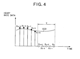
- a result obtained by conducting the weighted addition on heart rate data X at points in time which are included in n consecutive points in time and which are not included in the missing section and on the average heart rate data AV at points in time which are included in the missing section is generated as heart rate data CCD representing the heart rate of the driver.
- heart rate data X (1) to X (n) are effective data
- heart rate data represented as below is output.
- CCD a 1 •X (1) +a 2 •X (2) +a 3 •X (3) +a 4 •X (4) +a 5 •X (5) +, ⁇ , +a n-1 •X (n-1) +a n •X (n)
- AV average value
- CCD a 1 •X (1) +a 2 •X (2) +a 3 •X (3) +a 4 •X (4) +a 5 •X (5) +, ⁇ , +AV•X (n-4) +AV•X (n-3) +AV•X (n-2) +AV•X (n-1) +AV•X (n)
- the heart rate detection apparatus which detects heart rate as biological information of a driver has been described.
- biological information to be detected is not limited to the heart rate, but the present invention can be applied to various biological information detection apparatuses for pulsebeat, respiration, temperature, skin resistance, blood pressure, brain waves, or the like.
- each of the band pass filter 13 , the heart rate data detection circuit 14, the missing detection circuit 15, the selector 16, the FIR filter 17, the missing interpolation control circuit 18 and the switch 19 has a hardware configuration.
- these functions may be implemented by software.
Landscapes
- Health & Medical Sciences (AREA)
- Life Sciences & Earth Sciences (AREA)
- Engineering & Computer Science (AREA)
- Physics & Mathematics (AREA)
- Veterinary Medicine (AREA)
- Cardiology (AREA)
- Biomedical Technology (AREA)
- Heart & Thoracic Surgery (AREA)
- Medical Informatics (AREA)
- Molecular Biology (AREA)
- Surgery (AREA)
- Animal Behavior & Ethology (AREA)
- General Health & Medical Sciences (AREA)
- Public Health (AREA)
- Biophysics (AREA)
- Pathology (AREA)
- Signal Processing (AREA)
- Physiology (AREA)
- Automation & Control Theory (AREA)
- Mechanical Engineering (AREA)
- Business, Economics & Management (AREA)
- Emergency Management (AREA)
- General Physics & Mathematics (AREA)
- Measuring Pulse, Heart Rate, Blood Pressure Or Blood Flow (AREA)
- Measurement And Recording Of Electrical Phenomena And Electrical Characteristics Of The Living Body (AREA)
- Arrangements For Transmission Of Measured Signals (AREA)
- Measurement Of The Respiration, Hearing Ability, Form, And Blood Characteristics Of Living Organisms (AREA)
- Measuring And Recording Apparatus For Diagnosis (AREA)
Abstract
Description
Claims (4)
- A biological information detection apparatus which detects biological information of a human body, characterized in that the biological information detection apparatus comprises:a sensor (11a, 11b, 12, 13, 14) which detects an electric signal corresponding to the biological information from the human body as a biological signal;a missing detection device (15) which detects a missing section of the biological signal;a storage device (D1 to Dn-1) which stores the biological signal at each of n (where n is a natural number) consecutive points in time;an average calculation device (18) which calculates an average value of the biological signal at points in time which are included in the n points in time and which are not included in the missing section;a weighted addition device (SL1 to SLn, K1 to Kn, AD) which outputs a result obtained by conducting weighted addition on the biological signal at the n points in time, as a final biological signal; anda missing interpolation device (18) which, in conducting the weighted addition, changes the biological signal at each of the points in time included in the missing section to the average value.
- The biological information detection apparatus according to claim 1, characterized in that the storage device (D1 to Dn-1) changes the biological signal at each of the points in time included in the missing section to a predetermined value and stores the predetermined value.
- The biological information detection apparatus according to claim 1, characterized in that the weighted addition device (SL1 to SLn, K1 to Kn, AD) comprises a device (18, 19) which stops outputting the biological signal when a total number of points in time which are included in the n points in time and which are not included in the missing section is less than a first predetermined number.
- The biological information detection apparatus according to claim 3, characterized in that the biological information detection apparatus further comprising an alarm device (20) which gives an alarm when the total number of points in time which are included in the n points in time and which are not included in the missing section is less than a second predetermined number which is greater than the first predetermined number.
Applications Claiming Priority (2)
| Application Number | Priority Date | Filing Date | Title |
|---|---|---|---|
| JP2003132743 | 2003-05-12 | ||
| JP2003132743A JP3966833B2 (en) | 2003-05-12 | 2003-05-12 | Biological information detection device |
Publications (3)
| Publication Number | Publication Date |
|---|---|
| EP1477370A2 true EP1477370A2 (en) | 2004-11-17 |
| EP1477370A3 EP1477370A3 (en) | 2005-12-14 |
| EP1477370B1 EP1477370B1 (en) | 2006-11-15 |
Family
ID=33028315
Family Applications (1)
| Application Number | Title | Priority Date | Filing Date |
|---|---|---|---|
| EP04252718A Expired - Lifetime EP1477370B1 (en) | 2003-05-12 | 2004-05-11 | Biological information of a driver detection apparatus |
Country Status (4)
| Country | Link |
|---|---|
| US (1) | US7134997B2 (en) |
| EP (1) | EP1477370B1 (en) |
| JP (1) | JP3966833B2 (en) |
| DE (1) | DE602004003166T2 (en) |
Cited By (2)
| Publication number | Priority date | Publication date | Assignee | Title |
|---|---|---|---|---|
| JP2004329735A (en) * | 2003-05-12 | 2004-11-25 | Pioneer Electronic Corp | Biological information detector |
| WO2011111056A1 (en) * | 2010-03-12 | 2011-09-15 | Tata Consultancy Services Limited | A system for vehicle security, personalization and cardiac activity monitoring of a driver |
Families Citing this family (19)
| Publication number | Priority date | Publication date | Assignee | Title |
|---|---|---|---|---|
| AU2005222712A1 (en) | 2004-03-18 | 2005-09-29 | Helicor Inc. | Methods and devices for relieving stress |
| CN1956680A (en) * | 2004-05-24 | 2007-05-02 | 日本先锋公司 | Biological information detection device |
| US8002711B2 (en) * | 2005-03-18 | 2011-08-23 | Respironics, Inc. | Methods and devices for relieving stress |
| US20080071177A1 (en) * | 2005-04-28 | 2008-03-20 | Pioneer Corporation | Bioinformation Sensor |
| JP4289413B2 (en) * | 2007-03-26 | 2009-07-01 | 株式会社デンソー | Biological information measuring device |
| WO2010143535A1 (en) * | 2009-06-08 | 2010-12-16 | 公立大学法人名古屋市立大学 | Sleepiness assessment device |
| DE102012002037B4 (en) | 2012-02-03 | 2015-03-05 | automation & software Günther Tausch GmbH | Device for carrying out driver status analyzes |
| DE202012001096U1 (en) | 2012-02-03 | 2012-05-03 | automation & software Günther Tausch GmbH | Device for carrying out driver status analyzes |
| CN103315728B (en) * | 2012-03-20 | 2015-12-09 | 深圳市飘浮互动科技有限公司 | Heart rate detection and display packing and device thereof |
| JP5884681B2 (en) * | 2012-08-29 | 2016-03-15 | 株式会社デンソー | Signal processing apparatus and program |
| JP6519344B2 (en) * | 2015-06-25 | 2019-05-29 | 富士通株式会社 | Heartbeat interval specifying program, heart beat interval specifying device, and heart beat interval specifying method |
| DE102015013841B4 (en) | 2015-10-23 | 2020-07-09 | Thomas Körber | System for monitoring the driver in a vehicle |
| US10524735B2 (en) | 2017-03-28 | 2020-01-07 | Apple Inc. | Detecting conditions using heart rate sensors |
| JP6846288B2 (en) * | 2017-06-02 | 2021-03-24 | 日本電信電話株式会社 | Instantaneous heart rate time series data complement device, complement method and its program |
| DE102017129406A1 (en) * | 2017-12-11 | 2019-06-13 | Christian Möstl | SYSTEM AND METHOD FOR CONTROLLING HAND POSITIONS IN A VEHICLE'S INTERIOR |
| JP6956974B2 (en) * | 2017-12-12 | 2021-11-02 | 株式会社テクノアクセルネットワークス | Heart rate data output device, heart rate data output method, heart rate data output program and pacemaker |
| CN112790744A (en) * | 2020-03-24 | 2021-05-14 | 张武 | Health detection and analysis system for multi-union data |
| US20230389849A1 (en) * | 2022-06-03 | 2023-12-07 | Apple Inc. | Cardiac Monitoring and Management System |
| US12565225B2 (en) | 2023-07-24 | 2026-03-03 | Caterpillar Paving Products Inc. | Work machine control based on biometrics |
Family Cites Families (15)
| Publication number | Priority date | Publication date | Assignee | Title |
|---|---|---|---|---|
| US4420000A (en) * | 1981-09-28 | 1983-12-13 | Camino Laboratories, Inc. | Method and apparatus for measuring heartbeat rate |
| JPS5969059A (en) * | 1982-10-15 | 1984-04-19 | 松下電工株式会社 | Pulse meter |
| US4706072A (en) * | 1983-11-30 | 1987-11-10 | Aisin Seiki Kabushiki Kaisha | Human condition monitoring and security controlling apparatus on a road-vehicle |
| JPS6384516A (en) * | 1986-09-30 | 1988-04-15 | アイシン精機株式会社 | Heart rate meter for car |
| JPH0341926A (en) * | 1989-07-07 | 1991-02-22 | Matsushita Electric Works Ltd | Detector for change in sleeping state and sleeping state controller |
| JPH06197888A (en) * | 1993-01-06 | 1994-07-19 | Mitsubishi Motors Corp | Doze warning device for vehicle |
| JP3113118B2 (en) * | 1993-03-09 | 2000-11-27 | マツダ株式会社 | Vehicle control device |
| JP3319140B2 (en) * | 1994-04-19 | 2002-08-26 | いすゞ自動車株式会社 | Heart rate variability waveform analysis method and apparatus |
| JP3619662B2 (en) * | 1998-02-18 | 2005-02-09 | パイオニア株式会社 | Biological information detection device |
| JP3727803B2 (en) * | 1999-03-18 | 2005-12-21 | パイオニア株式会社 | Biological information detection device |
| US6312382B1 (en) * | 1999-11-15 | 2001-11-06 | Ronald Mucci | Method and apparatus for extracting cardiac information from acoustic information acquired with an ultrasound device |
| JP4514372B2 (en) * | 2001-08-28 | 2010-07-28 | パイオニア株式会社 | Information providing system, information providing method, information providing program, server device in information providing system, and terminal device in information providing system |
| JP2003118421A (en) * | 2001-10-12 | 2003-04-23 | Pioneer Electronic Corp | Organism state measuring device and method, mobile body navigation system and method, library device, and computer program |
| JP4252268B2 (en) * | 2002-08-29 | 2009-04-08 | パイオニア株式会社 | Fatigue level determination system, fatigue level determination method, and fatigue level determination program |
| JP3966833B2 (en) * | 2003-05-12 | 2007-08-29 | パイオニア株式会社 | Biological information detection device |
-
2003
- 2003-05-12 JP JP2003132743A patent/JP3966833B2/en not_active Expired - Fee Related
-
2004
- 2004-05-11 DE DE602004003166T patent/DE602004003166T2/en not_active Expired - Lifetime
- 2004-05-11 US US10/842,475 patent/US7134997B2/en not_active Expired - Lifetime
- 2004-05-11 EP EP04252718A patent/EP1477370B1/en not_active Expired - Lifetime
Cited By (5)
| Publication number | Priority date | Publication date | Assignee | Title |
|---|---|---|---|---|
| JP2004329735A (en) * | 2003-05-12 | 2004-11-25 | Pioneer Electronic Corp | Biological information detector |
| WO2011111056A1 (en) * | 2010-03-12 | 2011-09-15 | Tata Consultancy Services Limited | A system for vehicle security, personalization and cardiac activity monitoring of a driver |
| CN102469948A (en) * | 2010-03-12 | 2012-05-23 | 塔塔咨询服务有限公司 | Systems for Vehicle Safety, Personalization, and Cardiac Activity Monitoring for Drivers |
| CN102469948B (en) * | 2010-03-12 | 2015-06-03 | 塔塔咨询服务有限公司 | A system for vehicle security, personalization and cardiac activity monitoring of a driver |
| US9144389B2 (en) | 2010-03-12 | 2015-09-29 | Tata Consultancy Services Limited | System for vehicle security, personalization and cardiac activity monitoring of a driver |
Also Published As
| Publication number | Publication date |
|---|---|
| DE602004003166T2 (en) | 2007-09-06 |
| EP1477370B1 (en) | 2006-11-15 |
| DE602004003166D1 (en) | 2006-12-28 |
| JP3966833B2 (en) | 2007-08-29 |
| JP2004329735A (en) | 2004-11-25 |
| US7134997B2 (en) | 2006-11-14 |
| US20040230104A1 (en) | 2004-11-18 |
| EP1477370A3 (en) | 2005-12-14 |
Similar Documents
| Publication | Publication Date | Title |
|---|---|---|
| US7134997B2 (en) | Biological information detection apparatus | |
| US9480432B2 (en) | Processing of periodic physiological signals | |
| US9420958B2 (en) | System and method for determining changes in a body state | |
| JP4855721B2 (en) | Blood pressure measurement device | |
| CN101873826B (en) | Ear heart monitoring device and method | |
| EP2409638A1 (en) | Biological parameter monitoring method, computer program, and biological parameter monitoring device | |
| WO1998041143A1 (en) | Pulse wave detector and pulsimeter | |
| JP2003245258A (en) | Method and apparatus for monitoring contractions using linear predictive modeling of abdominal surface EMG signals | |
| RU2012101554A (en) | ECG CONTROL WITH REDUCED FALSE ALARMS IN CONNECTION WITH ASYSTOLIA | |
| JP3658580B2 (en) | Sleep depth estimating device and futon provided with the same | |
| US20110144461A1 (en) | Pulse frequency measuring method and apparatus | |
| JP3729143B2 (en) | Pulse wave measuring device | |
| US7130429B1 (en) | Method and an apparatus for processing auscultation signals | |
| US20190320926A1 (en) | Heartbeat detection method and heartbeat detection device | |
| US20200245875A1 (en) | Heartbeat detection device, heartbeat detection method, and program | |
| WO2007032226A1 (en) | Heart rate meter and method for removing noise of heart beat waveform | |
| JP4415466B2 (en) | Biological signal detection device and non-invasive blood pressure monitor | |
| JP7139959B2 (en) | Biological information detector | |
| JPH1189832A (en) | Fetal movement meter | |
| JP3829544B2 (en) | Sleep detection device | |
| EP2938247B1 (en) | Method and apparatus for reducing motion artifacts in ecg signals | |
| JP3952608B2 (en) | Heartbeat meter | |
| JP2018192128A (en) | Sleepiness determination apparatus and program | |
| CN109222945B (en) | Systems, methods, devices, and apparatus for fitness monitoring in a vehicle | |
| JP6531187B2 (en) | Body sound analysis device, body sound analysis method, computer program and recording medium |
Legal Events
| Date | Code | Title | Description |
|---|---|---|---|
| PUAI | Public reference made under article 153(3) epc to a published international application that has entered the european phase |
Free format text: ORIGINAL CODE: 0009012 |
|
| AK | Designated contracting states |
Kind code of ref document: A2 Designated state(s): AT BE BG CH CY CZ DE DK EE ES FI FR GB GR HU IE IT LI LU MC NL PL PT RO SE SI SK TR |
|
| AX | Request for extension of the european patent |
Extension state: AL HR LT LV MK |
|
| PUAL | Search report despatched |
Free format text: ORIGINAL CODE: 0009013 |
|
| AK | Designated contracting states |
Kind code of ref document: A3 Designated state(s): AT BE BG CH CY CZ DE DK EE ES FI FR GB GR HU IE IT LI LU MC NL PL PT RO SE SI SK TR |
|
| AX | Request for extension of the european patent |
Extension state: AL HR LT LV MK |
|
| 17P | Request for examination filed |
Effective date: 20051205 |
|
| GRAP | Despatch of communication of intention to grant a patent |
Free format text: ORIGINAL CODE: EPIDOSNIGR1 |
|
| AKX | Designation fees paid |
Designated state(s): DE FR GB |
|
| GRAS | Grant fee paid |
Free format text: ORIGINAL CODE: EPIDOSNIGR3 |
|
| GRAA | (expected) grant |
Free format text: ORIGINAL CODE: 0009210 |
|
| AK | Designated contracting states |
Kind code of ref document: B1 Designated state(s): DE FR GB |
|
| REG | Reference to a national code |
Ref country code: GB Ref legal event code: FG4D |
|
| REF | Corresponds to: |
Ref document number: 602004003166 Country of ref document: DE Date of ref document: 20061228 Kind code of ref document: P |
|
| REG | Reference to a national code |
Ref country code: GB Ref legal event code: 746 Effective date: 20070424 |
|
| ET | Fr: translation filed | ||
| PLBE | No opposition filed within time limit |
Free format text: ORIGINAL CODE: 0009261 |
|
| STAA | Information on the status of an ep patent application or granted ep patent |
Free format text: STATUS: NO OPPOSITION FILED WITHIN TIME LIMIT |
|
| 26N | No opposition filed |
Effective date: 20070817 |
|
| REG | Reference to a national code |
Ref country code: FR Ref legal event code: PLFP Year of fee payment: 13 |
|
| REG | Reference to a national code |
Ref country code: FR Ref legal event code: PLFP Year of fee payment: 14 |
|
| REG | Reference to a national code |
Ref country code: FR Ref legal event code: PLFP Year of fee payment: 15 |
|
| PGFP | Annual fee paid to national office [announced via postgrant information from national office to epo] |
Ref country code: DE Payment date: 20200428 Year of fee payment: 17 Ref country code: FR Payment date: 20200414 Year of fee payment: 17 |
|
| PGFP | Annual fee paid to national office [announced via postgrant information from national office to epo] |
Ref country code: GB Payment date: 20200430 Year of fee payment: 17 |
|
| REG | Reference to a national code |
Ref country code: DE Ref legal event code: R119 Ref document number: 602004003166 Country of ref document: DE |
|
| GBPC | Gb: european patent ceased through non-payment of renewal fee |
Effective date: 20210511 |
|
| PG25 | Lapsed in a contracting state [announced via postgrant information from national office to epo] |
Ref country code: GB Free format text: LAPSE BECAUSE OF NON-PAYMENT OF DUE FEES Effective date: 20210511 Ref country code: DE Free format text: LAPSE BECAUSE OF NON-PAYMENT OF DUE FEES Effective date: 20211201 |
|
| PG25 | Lapsed in a contracting state [announced via postgrant information from national office to epo] |
Ref country code: FR Free format text: LAPSE BECAUSE OF NON-PAYMENT OF DUE FEES Effective date: 20210531 |