EP1476104B1 - An insertion device for an electrode array - Google Patents
An insertion device for an electrode array Download PDFInfo
- Publication number
- EP1476104B1 EP1476104B1 EP03742445A EP03742445A EP1476104B1 EP 1476104 B1 EP1476104 B1 EP 1476104B1 EP 03742445 A EP03742445 A EP 03742445A EP 03742445 A EP03742445 A EP 03742445A EP 1476104 B1 EP1476104 B1 EP 1476104B1
- Authority
- EP
- European Patent Office
- Prior art keywords
- electrode array
- housing
- straightening
- engagement portion
- capture
- Prior art date
- Legal status (The legal status is an assumption and is not a legal conclusion. Google has not performed a legal analysis and makes no representation as to the accuracy of the status listed.)
- Expired - Lifetime
Links
- 238000003780 insertion Methods 0.000 title description 27
- 230000037431 insertion Effects 0.000 title description 27
- 210000003477 cochlea Anatomy 0.000 claims abstract description 70
- 238000000034 method Methods 0.000 claims abstract description 24
- 239000000463 material Substances 0.000 claims description 25
- 210000003813 thumb Anatomy 0.000 claims description 9
- 230000007246 mechanism Effects 0.000 claims description 8
- 239000004033 plastic Substances 0.000 claims description 8
- 229920003023 plastic Polymers 0.000 claims description 8
- 230000000694 effects Effects 0.000 claims description 7
- 229920001343 polytetrafluoroethylene Polymers 0.000 claims description 4
- 239000004810 polytetrafluoroethylene Substances 0.000 claims description 4
- -1 polypropylene Polymers 0.000 claims description 3
- 230000002028 premature Effects 0.000 claims description 3
- 239000004743 Polypropylene Substances 0.000 claims description 2
- 229920001155 polypropylene Polymers 0.000 claims description 2
- 210000003811 finger Anatomy 0.000 description 10
- 238000001356 surgical procedure Methods 0.000 description 7
- 210000000860 cochlear nerve Anatomy 0.000 description 6
- 230000000638 stimulation Effects 0.000 description 6
- 230000006378 damage Effects 0.000 description 5
- 230000008569 process Effects 0.000 description 5
- 241001611835 Modiola Species 0.000 description 4
- 230000008901 benefit Effects 0.000 description 4
- 239000007943 implant Substances 0.000 description 4
- 230000035807 sensation Effects 0.000 description 4
- 230000000295 complement effect Effects 0.000 description 3
- 230000005684 electric field Effects 0.000 description 3
- 229910052751 metal Inorganic materials 0.000 description 3
- 239000002184 metal Substances 0.000 description 3
- 210000005036 nerve Anatomy 0.000 description 3
- 230000002441 reversible effect Effects 0.000 description 3
- 230000007704 transition Effects 0.000 description 3
- 206010011878 Deafness Diseases 0.000 description 2
- 230000005540 biological transmission Effects 0.000 description 2
- 238000005516 engineering process Methods 0.000 description 2
- 210000002768 hair cell Anatomy 0.000 description 2
- 230000006872 improvement Effects 0.000 description 2
- 208000014674 injury Diseases 0.000 description 2
- 238000004519 manufacturing process Methods 0.000 description 2
- 210000001079 scala tympani Anatomy 0.000 description 2
- 230000005236 sound signal Effects 0.000 description 2
- 229910000811 surgical stainless steel Inorganic materials 0.000 description 2
- 210000001519 tissue Anatomy 0.000 description 2
- 230000008733 trauma Effects 0.000 description 2
- 230000000472 traumatic effect Effects 0.000 description 2
- RTAQQCXQSZGOHL-UHFFFAOYSA-N Titanium Chemical compound [Ti] RTAQQCXQSZGOHL-UHFFFAOYSA-N 0.000 description 1
- 230000009471 action Effects 0.000 description 1
- 239000000560 biocompatible material Substances 0.000 description 1
- 210000004556 brain Anatomy 0.000 description 1
- 230000008859 change Effects 0.000 description 1
- 238000004891 communication Methods 0.000 description 1
- 231100000895 deafness Toxicity 0.000 description 1
- 239000012777 electrically insulating material Substances 0.000 description 1
- 230000007613 environmental effect Effects 0.000 description 1
- 230000007717 exclusion Effects 0.000 description 1
- 230000006870 function Effects 0.000 description 1
- 210000004247 hand Anatomy 0.000 description 1
- 210000003128 head Anatomy 0.000 description 1
- 208000016354 hearing loss disease Diseases 0.000 description 1
- 230000004048 modification Effects 0.000 description 1
- 238000012986 modification Methods 0.000 description 1
- 238000004806 packaging method and process Methods 0.000 description 1
- 239000003973 paint Substances 0.000 description 1
- 239000011295 pitch Substances 0.000 description 1
- 229920001296 polysiloxane Polymers 0.000 description 1
- ZLIBICFPKPWGIZ-UHFFFAOYSA-N pyrimethanil Chemical compound CC1=CC(C)=NC(NC=2C=CC=CC=2)=N1 ZLIBICFPKPWGIZ-UHFFFAOYSA-N 0.000 description 1
- 238000011160 research Methods 0.000 description 1
- 230000004936 stimulating effect Effects 0.000 description 1
- 239000010966 surgical stainless steel Substances 0.000 description 1
- 210000003582 temporal bone Anatomy 0.000 description 1
- 229910052719 titanium Inorganic materials 0.000 description 1
- 239000010936 titanium Substances 0.000 description 1
Images













Classifications
-
- A—HUMAN NECESSITIES
- A61—MEDICAL OR VETERINARY SCIENCE; HYGIENE
- A61F—FILTERS IMPLANTABLE INTO BLOOD VESSELS; PROSTHESES; DEVICES PROVIDING PATENCY TO, OR PREVENTING COLLAPSING OF, TUBULAR STRUCTURES OF THE BODY, e.g. STENTS; ORTHOPAEDIC, NURSING OR CONTRACEPTIVE DEVICES; FOMENTATION; TREATMENT OR PROTECTION OF EYES OR EARS; BANDAGES, DRESSINGS OR ABSORBENT PADS; FIRST-AID KITS
- A61F11/00—Methods or devices for treatment of the ears or hearing sense; Non-electric hearing aids; Methods or devices for enabling ear patients to achieve auditory perception through physiological senses other than hearing sense; Protective devices for the ears, carried on the body or in the hand
-
- A—HUMAN NECESSITIES
- A61—MEDICAL OR VETERINARY SCIENCE; HYGIENE
- A61B—DIAGNOSIS; SURGERY; IDENTIFICATION
- A61B17/00—Surgical instruments, devices or methods
- A61B17/34—Trocars; Puncturing needles
- A61B17/3468—Trocars; Puncturing needles for implanting or removing devices, e.g. prostheses, implants, seeds, wires
-
- A—HUMAN NECESSITIES
- A61—MEDICAL OR VETERINARY SCIENCE; HYGIENE
- A61N—ELECTROTHERAPY; MAGNETOTHERAPY; RADIATION THERAPY; ULTRASOUND THERAPY
- A61N1/00—Electrotherapy; Circuits therefor
- A61N1/02—Details
- A61N1/04—Electrodes
- A61N1/05—Electrodes for implantation or insertion into the body, e.g. heart electrode
- A61N1/0526—Head electrodes
- A61N1/0541—Cochlear electrodes
-
- A—HUMAN NECESSITIES
- A61—MEDICAL OR VETERINARY SCIENCE; HYGIENE
- A61B—DIAGNOSIS; SURGERY; IDENTIFICATION
- A61B17/00—Surgical instruments, devices or methods
- A61B2017/00477—Coupling
-
- A—HUMAN NECESSITIES
- A61—MEDICAL OR VETERINARY SCIENCE; HYGIENE
- A61B—DIAGNOSIS; SURGERY; IDENTIFICATION
- A61B17/00—Surgical instruments, devices or methods
- A61B2017/00743—Type of operation; Specification of treatment sites
- A61B2017/00787—Surgery of the ear
-
- A—HUMAN NECESSITIES
- A61—MEDICAL OR VETERINARY SCIENCE; HYGIENE
- A61B—DIAGNOSIS; SURGERY; IDENTIFICATION
- A61B90/00—Instruments, implements or accessories specially adapted for surgery or diagnosis and not covered by any of the groups A61B1/00 - A61B50/00, e.g. for luxation treatment or for protecting wound edges
- A61B90/03—Automatic limiting or abutting means, e.g. for safety
- A61B2090/033—Abutting means, stops, e.g. abutting on tissue or skin
- A61B2090/034—Abutting means, stops, e.g. abutting on tissue or skin abutting on parts of the device itself
-
- A—HUMAN NECESSITIES
- A61—MEDICAL OR VETERINARY SCIENCE; HYGIENE
- A61N—ELECTROTHERAPY; MAGNETOTHERAPY; RADIATION THERAPY; ULTRASOUND THERAPY
- A61N1/00—Electrotherapy; Circuits therefor
- A61N1/18—Applying electric currents by contact electrodes
- A61N1/32—Applying electric currents by contact electrodes alternating or intermittent currents
- A61N1/36—Applying electric currents by contact electrodes alternating or intermittent currents for stimulation
- A61N1/36036—Applying electric currents by contact electrodes alternating or intermittent currents for stimulation of the outer, middle or inner ear
- A61N1/36038—Cochlear stimulation
Definitions
- the present invention relates to a device, method and system for the insertion of an electrode array into a cochlea of a subject and the simultaneous removal of a straightening means of the electrode array.
- cochlear implant systems have been developed. Such systems bypass the hair cells in the cochlea and directly deliver electrical stimulation to the auditory nerve fibres, thereby allowing the brain to perceive a hearing sensation resembling the natural hearing sensation normally delivered to the auditory nerve.
- US Patent 4532930 provides a description of one type of traditional cochlear implant system.
- cochlear implant systems have consisted of essentially two components, an external component commonly referred to as a processor unit and an internal implanted component commonly referred to as a stimulator/receiver unit. Traditionally, both of these components have cooperated together to provide the sound sensation to a user.
- the external component has traditionally consisted of a microphone for detecting sounds, such as speech and environmental sounds, a speech processor that converts the detected sounds, particularly speech, into a coded signal, a power source such as a battery, and an external transmitter coil.
- the coded signal output by the speech processor is transmitted transcutaneously to the implanted stimulator/receiver unit situated within a recess of the temporal bone of the user.
- This transcutaneous transmission occurs via the external transmitter coil which is positioned to communicate with an implanted receiver coil provided with the stimulator/receiver unit.
- This communication serves two essential purposes, firstly to transcutaneously transmit the coded sound signal and secondly to provide power to the implanted stimulator/receiver unit.
- this link has been in the form of a radio frequency (RF) link, but other such links have been proposed and implemented with varying degrees of success.
- RF radio frequency
- the implanted stimulator/receiver unit traditionally includes a receiver coil that receives the coded signal and power from the external processor component, and a stimulator that processes the coded signal and outputs a stimulation signal to an intracochlear electrode assembly which applies the electrical stimulation directly to the auditory nerve producing a hearing sensation corresponding to the original detected sound.
- the external componentry has been carried on the body of the user, such as in a pocket of the users' clothing, a belt pouch or in a harness, while the microphone has been mounted on a clip behind the ear or on the lapel of the user.
- the physical dimensions of the speech processor have been able to be reduced allowing for the external componentry to be housed in a small unit capable of being worn behind the ear of the user.
- This unit allows the microphone, power unit and the speech processor to be housed in a single unit capable of being discretely worn behind the ear, with the external transmitter coil still positioned on the side of the user's head to allow for the transmission of the coded sound signal from the speech processor and power to the implanted stimulator unit.
- the cochlea is tonotopically mapped.
- the cochlea can be partitioned into regions, with each region being responsive to signals in a particular frequency range.
- This property of the cochlea is exploited by providing the electrode assembly with an array of electrodes, each electrode being arranged and constructed to deliver a cochlea stimulating signal within a preselected frequency range to the appropriate cochlea region. The electrical currents and electric fields from each electrode stimulate the nerves disposed on the modiola of the cochlea.
- the magnitude of the currents flowing from these electrodes and the intensity of the corresponding electric fields are a function of the distance between the electrodes and the modiola. If this distance is relatively great, the threshold current magnitude must be larger than if the distance is relatively small. Moreover, the current from each electrode may flow in all directions, and the electrical fields corresponding to adjacent electrodes may overlap, thereby causing cross-electrode interference. In order to reduce the threshold stimulation amplitude and to eliminate cross-electrode interference, it is advisable to keep the distance between the electrode array and the modiola as small as possible. This is best accomplished by providing the electrode array in the shape which generally follows the shape of the modiola. Also, this way the delivery of the electrical stimulation to the auditory nerve is most effective as the electrode contacts are as close to the auditory nerves that are particularly responsive to selected pitches of sound waves.
- the electrode In order to achieve this electrode array position close to the inside wall of the cochlea, the electrode needs to be designed in such a way that it assumes this position upon or immediately following insertion into the cochlea. This is a challenge as the array needs to be shaped such that it assumes a curved shape to conform with the natural shape of the inside wall of the cochlea and must also be shaped such that the insertion process causes minimal trauma to the sensitive structures of the cochlea. In this sense, it is desirable that the electrode array is held in a generally straight configuration at least during the initial stages of the insertion procedure.
- an electrode array that includes a spiral-shaped carrier which has a natural spiral shape generally conforming to the configuration of a cochlea.
- Such an array may also include a straightening element or stylet to enable the carrier to be maintained in a straight configuration for insertion.
- the straightening member is then typically removed from the carrier following insertion thereby allowing the carrier to take on its natural spiral-shape and assume a position adjacent the inner wall of the cochlea.
- the straightening member is removed following the insertion of the electrode array into the cochlea by clamping an exposed end of the straightening member with tweezers and gradually removing the stylet. This technique is difficult to coordinate and requires both hands of a surgeon to perform.
- the present invention is directed to an insertion tool for an electrode assembly which is constructed to address the abovementioned problems of prior devices.
- the present invention provides a device as set forth in claim 1, and a method of using this device as set forth in claim 46.
- the electrode array is configured to be implanted in a cochlea of a subject.
- the housing may include a handle and a tip member wherein the handle and tip member may be integral with one another or alternatively, the tip may be removably connected to the handle.
- the housing may also include an inner member positioned at least partially within an outer member.
- the electrode array positioning member may comprise a number of structures and may be moved from its first position to its second position by a number of means. In each embodiment discussed below, it may be seen that movement of the electrode array positioning member in a direction towards the distal end of the housing relative to a substantially fixed capture member allows the electrode array which has been loaded onto the device to effectively "advance off' the straightening member.
- said electrode array positioning member comprises an elongate member that substantially extends through said housing from a first end to a second end, said second end adapted to engage part of the electrode array.
- the electrode array positioning member may be connected to the handle of the housing such that as the handle is moved in a direction towards the distal end of the housing, said electrode array positioning member is also moved in said direction.
- this embodiment enables a surgeon to manipulate the device of the present invention much like a pen.
- the electrode array positioning member may comprise a plunger member.
- a length of the electrode array positioning member adjacent the first end of the electrode array positioning member extends beyond the proximal end of the housing.
- the plunger member typically includes an actuator member at its first end wherein said actuator member, which may be a thumb rest, is adapted to abut with the proximal end of the housing. This abutment limits movement of the electrode array positioning member towards the distal end of the housing thus ensuring that a user does not advance an electrode array too far into a cochlea of a subject.
- the electrode array positioning member may be connected to or brought into engagement with a slider such that movement of the slider towards the distal end of the housing causes movement of said electrode array positioning member in said direction.
- the slider may move along a slot in the wall of the housing and include finger rests to enable a user to move the slider along said slot.
- the second end of the electrode array positioning member may be forked, grooved or slotted to optimise engagement with the electrode array.
- the electrode array positioning member adjacent the second end may comprise a substantially hollow cylinder defining an internal lumen therein.
- the lumen of the electrode array positioning member also receives an engagement portion of the straightening member of the electrode array.
- the electrode array positioning member may include a grooved or recessed portion at or adjacent its second end to receive the engagement portion of the straightening member.
- the housing may include an inner member and an outer member.
- the inner member and the outer member typically make up part of the tip member of the housing and are configured such that one of said inner member or outer member is fixed relative to the other member such that the relatively “movable” member may include the electrode array positioning member and the substantially “fixed” member may include the capture member.
- the capture member may include a number of structures but in each embodiment has the feature that it engages and "captures" the engagement portion of the straightening member such that as the electrode array is advanced into a cochlea of a subject during a procedure, the engagement portion of the straightening member is held by the capture member and the electrode array is allowed to "advance off" the straightening member.
- the capture member may be essentially fixed relative to the electrode array positioning member.
- the capture member does not substantially move in a direction towards the distal end of the housing of the device, which, when the device is in use, is towards a cochlea of a subject. It is envisaged, however, that the capture member may be moved relatively in a direction away from the distal end of the housing such that the straightening member of the electrode array may be fully removed from an electrode array.
- the capture member may comprise an elongate member which extends from one end to a capture end. At or adjacent the capture end said capture member may include a flap, hook, loop or tie or any member capable of engaging with the engagement portion of the straightening member when said electrode array is loaded onto the device of the present invention.
- the capture end may include a pair of jaw members which are movable from a first open position to a second closed position such that in the second closed position, the jaw members clamp around the engagement portion of the straightening member.
- the capture member may include a member positioned on or forming part of a wall of the housing.
- the capture member may be positioned on one of said inner or outer members.
- one of the inner member or the outer member is movable relative to the other that is substantially fixed.
- the capture member may be positioned on said substantially fixed member.
- the capture member may include a flap, hook, loop or tie or any member capable of engaging with the engagement portion of the straightening member.
- At least a portion of the electrode array positioning member adjacent its second end includes a slot along its wall. Said slotted portion may receive at least part of the capture member.
- the capture end of the capture member may comprise a substantially hollow cylinder.
- the second end or a portion adjacent the second end of the electrode array positioning member is receivable within a lumen formed by the substantially hollow cylinder of the capture member.
- the flap, hook, loop or tie member of the capture member preferably extends inwardly of the capture end such that it may engage the engagement portion of the straightening member received by the electrode array positioning member.
- the capture member is positioned on a wall of an inner member or an outer member of the tip member of the housing, it is preferred that the inner member and the outer member are substantially hollow in structure such that the inner member is slidably receivable within the outer member.
- the electrode array positioning member may comprise the inner member.
- the capture member is positioned on the outer member such that at least part of the capture member extends through the slotted portion of the electrode array positioning member.
- the electrode array positioning member may comprise the outer member and the inner member includes the capture member.
- the electrode array may be received within both the inner and the outer members such that the engagement portion of the straightening member of the electrode array expends into the lumen of the inner member and engages with the capture member. The outer member engages the electrode array such that as the outer member is moved so too is the electrode array.
- the capture member preferably includes a flap member made from a resiliently flexible material such as a plastics material.
- the principle of capture of the engagement portion of the straightening member of the electrode array relies upon movement or deformation of the flap member caused by movement of the engagement portion through the lumen of the electrode array positioning member as the electrode array is loaded onto the device of the invention.
- the force of the moving engagement portion of the straightening member against the flap member causes the flap member to move from a first position substantially occluding the lumen of the electrode array positioning member to a second position which allows passage of the engagement portion of the straightening member past the flap member.
- the "deforming" force ie.
- said flap member may return to its original configuration such that it substantially occludes the lumen of the electrode array positioning member and prevents the engagement portion from moving in a reverse direction. This may be achieved in a number of ways as discussed in further detail below.
- the capture member may include a hook, press stud, or other like member that extends from the capture member and into the lumen of the electrode array positioning member whereupon it engages a complementary structure such as a loop member comprising the engagement portion of the straightening member.
- the jaw members are made from a suitably malleable material to allow movement of said jaw members from a first open position to a second closed position.
- the jaw members may be moved to their closed position by movement of the electrode array positioning member.
- the capture member may be positioned within at least the substantially hollow cylinder of the second end of the electrode array positioning member such that the jaw members extend beyond the second end and flare outwardly from said second end. Movement of the electrode array positioning member to its second position causes the second end of the electrode array positioning member to abut with the flared out jaw members.
- the continued force applied to the jaw members as the electrode array positioning member moves from its first to its second position causes said jaw members to deform and take on their second closed position thereby capturing the engagement portion of the straightening member of an electrode array loaded onto the device.
- the straightening member of the electrode array typically extends through a central lumen or along a slot in the electrode array from a proximal end of said electrode array to a leading tip of the electrode array.
- the straightening member acts to straighten a pre-curved electrode array thus enabling insertion of the electrode array through a cochleostomy and into the cochlea.
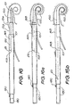
- said engagement portion of the straightening member which is captured by the capture member extends beyond the proximal end of the electrode array and may include a number of structures including but not limited to a substantially spherical member, a hemispherical member, a conical member, a bullet-like member, or an arrow-shaped member.
- the engagement portion may include a loop or other like structure or a combination of a loop with any one of the substantially spherical, hemispherical, conical, bullet-like, or arrow-shaped members.
- the loop is located furthest from the electrode array than either the substantially spherical, hemispherical, conical, bullet-like, or arrow-shaped member. This has the advantage that a surgeon may maintain the option of inserting the electrode array manually wherein the loop may be more easily captured by a hand tool such as a hook, forceps, tweezers or the like.
- the engagement portion of the straightening member may comprise a structure such as a substantially spherical, hemispherical, conical, bullet-like, or arrow-shaped member having an aperture therein such that said aperture may act as a means of manual capture of the straightening member and the substantially spherical, hemispherical, conical, bullet-like, or arrow-shaped member as a means of deforming the flap member and resulting in capture of the engagement portion of the straightening member.
- the electrode array may be loaded into a cartridge member with the engagement portion of the straightening member extending from one end of the cartridge member.
- the end of the cartridge member with the engagement portion of the straightening member extending therefrom is received within the distal end of the housing of the device.
- said portion of the straightening device may be caused to move through the lumen of the substantially hollow portion of the electrode array positioning member and along the slotted portion of the electrode array positioning member.
- the capture member may extend into the slot formed in the wall of said slotted portion.
- the capture member includes a flap member
- the flap member typically extends into and substantially occludes the lumen of the hollow cylinder of the electrode array positioning member.
- the flap member is made from a resiliently flexible material, as the engagement portion of the straightening member is moved into and along the slotted portion of the electrode array positioning member, the engagement portion of the straightening member is forced against the flap member causing said flap member to move or deform such that it no longer substantially occludes the lumen of the electrode array positioning member. This allows the engagement portion of the straightening member to pass the flap member.
- the flap member may resume its original configuration extending through the slot of the slotted portion of the electrode array positioning member and into the lumen of the electrode array positioning member and substantially occluding said lumen.
- the flap member may only be movable or deformable in one direction to allow the engagement portion of the straightening member to pass.
- the flap member therefore acts as a "one-way gate" for the engagement portion of the straightening member.
- the second end of the electrode array positioning member when the electrode array is loaded onto the device, the second end of the electrode array positioning member abuts with the proximal end of the electrode array.
- the electrode array positioning member comprises a plunger member
- the plunger member when the plunger member is moved in a direction towards the distal end of the housing, the second end of the electrode array positioning member pushes the proximal end of the electrode array such that the electrode array is advanced from the distal end of the housing, and when used in a surgical procedure, advanced into a cochlea of a subject.
- the engagement portion of the straightening member captured by the flap member is held by the "one way gate” system of the flap member and thus prevented from advancing with the electrode array.
- the entire straightening member is, therefore, prevented from advancing into the cochlea with the electrode array and the electrode array "advances off" the straightening member and into the cochlea.
- the electrode array may then start to take on a pre-curved configuration within the cochlea of the subject.
- the capture member may be moved in a direction towards the proximal end of the housing.
- the capture member includes a flap member, such movement causes the flap member to abut with part of the engagement portion of the straightening member and pull the engagement portion of the straightening member along the slotted portion of the electrode array positioning member in a direction towards the proximal end of the housing.
- the capture member may be connected to a slide member which may be positioned on an outer wall of the housing or, alternatively, within the housing and having a portion extending from the housing to enable manipulation of said slide member by a user.
- the capture member may be connected to said slide member by a number of means including by a tie member or, alternatively, by a pulling rod.
- the slide member typically includes two fingers rests which extend from said slide member and through two opposing slots in the wall of the housing. A user may therefore move the finger rests along the slots of the housing to effect movement of the capture member. Movement of the finger rests in a direction towards the proximal end of the housing typically effects full withdrawal of the straightening member from the electrode array.
- the device of the present invention may further comprise a safety mechanism to prevent withdrawal of the straightening member before the electrode array positioning member has moved to its second position and the electrode array advanced into the cochlea of a subject.
- the slide member has a spring member housed in a recess of said slide member.
- the spring member is preferably made from a resiliently flexible material and includes a main body which, on one side is hingedly connected to a leg member. On an opposing side of the main body, the spring member includes a housing engagement portion which extends from the main body and into a niche in the inner wall of the housing of the device. When the housing engagement portion is positioned within the niche of the housing, any movement of the spring member and the slide member relatively towards or away from the distal end of the housing is prevented.
- the slide member and the main body of the spring member may further include a groove which receives a portion of the electrode array positioning member thereby allowing the electrode array positioning member to pass through the groove of the slide member as the electrode array positioning member is moved from its first to its second position.
- the electrode array positioning member comprises a number of components connected to or integral with one another.
- the electrode array positioning member includes a plunger member made up of a thumb rest connected to or integral with a pushing arm.
- the thumb rest and pushing arm are preferably made from a relatively hard material such as a hard plastics material.
- the pushing arm may be connected to or integral with an intermediate member which is typically made from a relatively more flexible material than the thumb rest and pushing arm. Further, the intermediate member can have a smaller cross-sectional diameter than the pushing arm.
- the intermediate member is connected to or integral with an end member which receives the electrode array.
- the end member is typically made from a suitably biocompatible material such as surgical stainless steel or titanium.
- a portion of the pushing arm adjacent its connection with the intermediate member is tapered to form a shoulder.
- the intermediate member typically passes along the groove of the slide and spring member when the plunger is actuated and the electrode array is advanced into a cochlea. Movement of the intermediate member along the groove of the spring member does not disrupt the configuration of the resiliently flexible spring member. Accordingly, if the spring member is positioned such that the housing engagement member is within the niche in the housing, movement of the intermediate member of the electrode array positioning member along the groove does not dislodge said housing engagement member and the spring member, slide member and the capture member (which is connected to the slide member) are therefore prevented from moving either in a direction relatively towards or away from the distal end of the housing, that is, each of these components are fixed relative to the housing and the electrode array positioning member. This enables the electrode array positioning member to be moved to its second position without the risk of the straightening member of the electrode array being withdrawn prematurely from said array.
- the tapered portion of the pushing arm extends into the groove in the spring member.
- the shoulder of the pushing arm pushes against a wall of the groove of the main body, causing the main body to move about its hinged joint with the leg member from a first position wherein the main body is relatively spaced from the leg member to a second position wherein said main body is relatively less spaced from the leg member.
- the leg member is substantially prevented from moving relative to the main body as it is relatively securely housed within a complementary structure of the slide member. Movement of the main body of the spring member relative to the leg member disengages the housing engagement member from the niche in the inner wall of the housing. With the housing engagement member disengaged from the inner wall of the housing, the slide member and the capture member are free to be moved by way of the finger rests in a direction towards the proximal end of the housing.
- the distal end of the housing abuts with the cochlea during the entire procedure of insertion of the electrode array and removal of the straightening member from the electrode array.
- the device may include a safety mechanism to prevent the distal end of the housing advancing too far into a cochlea of a subject.
- the device may include a cochleostomy stopper at or adjacent the distal end which abuts with an edge of a cochleostomy.
- the device may include at least one stopper member which prevents the electrode array positioning member from moving beyond a predetermined position.
- the stopper member may include an engagement member which engages with a latch member when the electrode array positioning member is in its second position. Such engagement with said latch member prevents the electrode array positioning member moving any further beyond the second position.
- the latch member may be positioned on any part of the device including on a wall of the housing or may form part of the capture member.
- the limiting factor in this case may be the length of a slot in the housing along which the slider may travel.
- a portion of the electrode array extends a distance of approximately 7 to 10 mm from the distal end of the housing.
- the leading tip of the electrode array is positioned in the middle of the lumen near the back of the basal turn of the scala tympani such that said leading tip of the electrode does not exert pressure on the surrounding tissue.
- the electrode array As the electrode array is moved to its second position by movement of the electrode array positioning member, the electrode array continues to follow a trajectory along the middle of the lumen of the scala tympani thereby avoiding pressure on the lateral wall of the cochlea thus minimising the potential for trauma to the lateral wall and the modiolar wall.
- the device of the present invention may further include a means to release an electrode array loaded thereon.
- the electrode array may be released by a surgeon should manual insertion be preferred.
- the device of the present invention includes a safety clip member to prevent premature movement of the electrode array positioning member and thus movement of the electrode array.
- a safety clip member to prevent premature movement of the electrode array positioning member and thus movement of the electrode array.
- the safety clip may be positioned in engagement with the electrode array positioning member at or adjacent its first end.
- the safety clip may further abut with a portion of the housing such that the electrode array positioning member is prevented from moving to its second position.
- the safety clip is included in the packaging of the device to provide support during shipment and transportation. As a result, once unpacked, the device is in the correct position for an assembled cartridge and electrode array to be attached.
- the housing of the device may be made from a plastics material such as polytetrafluoroethylene (PTFE) or polypropylene.
- the housing may be made from a metal such as surgical steel, or a combination of metal and/or plastic. The choice of material may depend upon whether the device is manufactured as a re-usable or a disposable device.
- the housing is tapered towards the distal end. Further, it is preferred that the housing is angled in structure such as to provide a good line of vision for a surgeon during insertion of the electrode array.
- the electrode array positioning member and the capture member may also be angled along their length to correspond with the angled structure of the housing. Preferably, the angle of the housing is in the region of 20 to 30°.
- the housing includes a handle and a tip member wherein the tip member is angled relative to the handle.
- the tip member may be removably connected to the handle. Further, the tip member may be rotated relative to the handle such that rotational orientation of an electrode array loaded on the device may be set by a surgeon as desired or preferred for each surgery.
- a region of the housing adjacent the distal end includes a window to allow a user to view the electrode array during loading of the electrode array onto the device.
- the user should be able to view the engagement portion of the straightening member of the electrode array which is captured by the capture member through the window.
- the electrode array may be mounted on the device during the manufacture of the device. Typically, however, the electrode array is mounted on the device by a surgeon, immediately prior to surgery.
- the device of the present invention further comprises a cartridge member for an electrode array, said electrode array having a straightening member, the cartridge member including an elongate body extending from a first end to a second end, said elongate body having an internal lumen extending therethrough which is adapted to receive the electrode array; the cartridge member further including a window in a portion of the sidewall of the elongate body adjacent the first end wherein said window enables a user to view a portion of the electrode array.
- the electrode array may be loaded onto the cartridge member by feeding a portion of the straightening member of the electrode array which extends from said electrode array into the second end of the cartridge member.
- the elongate body further includes a slot along at least a portion of its length to accommodate the leads of the electrode array.
- the slot is substantially straight and constant in width as it extends along said at least a portion of the elongate body.
- the electrode array is preferably oriented such that the electrical leads of the electrode array are substantially aligned with said slot of the cartridge member.
- the electrode array may then be guided into the cartridge member by pulling lightly on the electrical leads of the electrode array until the portion of the straightening member which extends from the electrode array also extends from the first end of the cartridge member.
- the cartridge member and electrode array may be used with the device disclosed in the first aspect of the invention wherein the cartridge member may be loaded onto the distal end of the housing of the device and the electrode array positioning member of the device caused to engage the electrode array within the cartridge member.
- the cartridge may come pre-loaded with the electrode array or, alternatively, a surgeon may load the electrode array onto the cartridge prior to a procedure.
- a portion of the housing adjacent the distal end of the housing of the device includes a window.
- the window of the cartridge member is aligned with the window in the housing of the device.
- the cartridge member and electrode array may be taken to be correctly mounted and a user may then commence with the surgical procedure.
- the cartridge may be made from a number of materials and is preferably made from an electrically insulating material.
- the cartridge includes an electrically insulating layer between the elongate body of the cartridge member and the electrode array.
- a metal cartridge member may be coated on an inner wall defining the lumen of the main body with, for example, ParalyneTM, PTFE, a lubricious silicone, or a plastic paint such as ABS.
- the device of the present invention further provides an electrode array, the electrode array including an elongate body which extends from a proximal end to a distal end and a straightening member extending along at least part of the length of the elongate body wherein at least a portion of the straightening member extends beyond the proximal end of the elongate body, said at least a portion including a substantially spherical member, a substantially hemispherical member or an arrow-shaped member.
- a device of one embodiment of the present invention is generally depicted as 10 in the accompanying drawings.
- the device 10 is used for inserting an electrode array 100 into a cochlea of a subject and removing a straightening member 101 of the electrode array 100.
- the device comprises a housing 11 which extends from a proximal end 12 to a distal end 13.
- the distal end 13 is adapted to receive a portion of the electrode array 100.
- the device further comprises an electrode array positioning member 14 which extends through the housing 11 from a first end 15 to a second end 16.
- the second end 16 engages part of the electrode array 100 such that movement of the electrode array positioning member 14 from a first position to a second position effects movement of the electrode array 100 from a first position substantially within the housing 11 to a second position substantially extending from the distal end 13 of the housing 11.
- the device 10 also has a capture member 17 which extends through the housing 11 from one end 23 to a capture end 24.
- the capture end 24 engages a portion of the straightening member 101 of the electrode array 100 such that the straightening member 101 is restricted from moving with the electrode array 100 from its first position substantially within the housing 11 to its second position substantially extending from the distal end 13 of the housing 11.
- the electrode array positioning member 14 includes a plunger 18 at its first end 15.
- a user exerts pressure on the plunger 18 to cause movement of the electrode array positioning member 14 from its first position to its second position, that is in a direction towards the distal end 13 of the housing 11.
- the plunger 18 includes a thumb rest 19 which is adapted to abut with the proximal end 12 of the housing 11. This abutment limits movement of the plunger 18 towards the distal end 13 of the housing 11 thus ensuring that a user does not advance the electrode array 100 to an undesirable depth into a cochlea of a subject.
- a region 21 of the electrode array positioning member 14 adjacent to the second end 16 is slotted as depicted in Figure 3a .
- the slotted region 21 receives part of the straightening member 101 of the electrode array 100 as described in further detail below.
- the slotted region 21 may also include a window as depicted in Figure 3b .
- the slotted region 21 also receives a portion of the capture member 17.
- the capture member 17 comprises an elongate member 22 which extends from the one end 23 to the capture end 24.
- the capture member 17 includes a flap member 25 located adjacent the capture end 24.
- the flap member 25 is adapted to engage part of the straightening member 101 of the electrode array 100 when said electrode array 100 is loaded onto the device 10.
- the capture end 24 of the capture member 17 forms a hollow cylinder 26 which, when the device 10 is fully assembled, extends around the second end 16 or a portion adjacent thereto of the electrode array positioning member 14 (as shown in Figures 2 and 4 ).
- the flap member 25 extends from the capture end 24 and into the slotted region 21 of the electrode array positioning member 14.
- the straightening member 101 of the electrode array 100 extends through a central lumen or along a slot in the electrode array (not shown) and an engagement portion 103 extends beyond the proximal end 102 of the electrode array 100.
- the straightening member 101 acts to straighten a pre-curved electrode array thus enabling insertion of the electrode array into the cochlea.
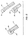
- the engagement portion 103 of the straightening member 101 includes a ball member 104, a loop 105, an arrow member 106, a bullet member 107 or a hemispherical member 108.
- the engagement portion includes loop 105 in combination with any one of ball member 104, arrow member 106, bullet member 107 or hemispherical member 108.
- loop 105 is located further from the electrode array 100 than either ball member 104, arrow member 106, bullet member 107 or hemispherical member 108.
- a surgeon may therefore maintain the option of inserting the electrode array 100 manually wherein the loop 105 may be more easily captured by a hand tool such as a hook, forceps, tweezers or the like.
- a hand tool such as a hook, forceps, tweezers or the like.
- the loop 105 is formed from an aperture 109 in bullet member 107.
- the aperture 109 enables a surgeon to capture the straightening member 101 with a hand tool as mentioned above.
- the electrode array 100 is loaded onto a cartridge member 29 with engagement portion 103 extending from one end of the cartridge member 29.
- the end of the cartridge member 29 with the engagement portion 103 extending therefrom is received within the distal end 13 of the housing 11.
- the engagement portion 103 moves through the slotted region 21 of electrode array positioning member 14.
- the flap member 25 of the capture member 17 extends into the slotted region 21.
- the flap member 25 is made from a resiliently flexible material, as the engagement portion 103 moves into and along the slotted region 21 of the electrode array positioning member 14, the flap member 25 is deformed by the engagement portion 103 as it passes said flap member 25. Once the engagement portion 103 has moved beyond the flap member 25, the flap member 25 resumes its original configuration, that is, extending through the slot of the slotted region 21 of the electrode array positioning member 14.
- the positioning of the flap member 25 extending through the slot of the slotted region 21 prevents any further movement of the engagement portion 103 in the reverse direction, that is, towards the second end 16 of the electrode array positioning member 14.
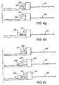
- Figure 6g to 6i show the engagement portion 103 passing the flap member 25.
- the engagement portion 103 includes ball member 104 whereas in Figure 6h , the engagement portion 103 includes a hemispherical member 108.
- the engagement portion 103 shown in Figure 6i includes an arrow member 106 which has the advantage that it is has a gradual and longer taper than the ball 104 or the hemisphere 108.
- the second end 16 of the electrode array positioning member 14 abuts with a proximal end 102 of the electrode array 100.
- the engagement portion 103 extends into the slotted region 21 of the positioning member 14 and is held within the slotted region 21 by the flap member 25.
- the second end 16 of the electrode array positioning member 14 pushes the proximal end 102 of the electrode array 100 such that the electrode array 100 is advanced from the distal end 13 of the housing 11, and when used in a surgical procedure, advanced into a cochlea of a subject.
- the engagement portion 103 of the straightening member 101 is held by the flap member 25 of the capture member 17 and therefore the straightening member 101 is restricted from advancing into the cochlea with the electrode array 100.
- the straightening member 101 with the electrode array 100 may be some advancement of the straightening member 101 with the electrode array 100, however such advancement will only be relatively minimal until the flap member 25 captures the engagement portion 103 of the of the straightening member 101. Accordingly, the electrode array 100 advances off the straightening member 101 and into the cochlea.
- the electrode array 100 may then start to take on a pre-curved configuration within the cochlea of the subject, allowing the electrode array to assume a mid scala trajectory into the cochlea which reduces the reliance on the sensitive structures of the walls of the cochlea to guide the electrode array into the cochlea. As a result, this provides a more efficient, safer, less traumatic, and potentially deeper electrode array insertion procedure.
- the capture member 17 is moved in a direction towards the proximal end 12 of the housing 11. Such movement causes the flap member 25 of the capture member 17 to abut with the engagement portion 103 of the straightening member 101 and pull said engagement portion 103 along the slotted region 21 of the electrode array positioning member 14 in a direction towards the proximal end 12 of the housing 11.
- the one end 23 of the capture member 17 is connected to a slide member 31, which when the device is fully assembled, is located within the housing 11.
- the slide member 31 includes two fingers rests 32 which extend from the slide member 31 through two opposing slots 33 in the wall of the housing 11. A user moves the finger rests 32 along the slots 33 to effect movement of the capture member 17. Movement of the finger rests 32 in a direction towards the proximal end 12 of the housing 11 will effect full withdrawal of the straightening member 101 from the electrode array 100.
- the device 10 further comprises a safety mechanism to prevent withdrawal of the straightening member 101 before the electrode array positioning member 14 has moved to its second position and the electrode array 100 advanced into the cochlea of a subject.
- the slide member 31 further includes a spring member 34 which is housed within a recess in the slide member.
- the spring member 34 is made from a resiliently flexible material and includes a main body 35 which on one side 36 is hingedly connected to a leg member 37. On an opposing side 38 of the main body 35, the spring member 34 includes a housing engagement portion 39 which extends from the main body 3 5 and into a niche (not shown) in the inner wall of the housing 11 of the device 10.
- any movement of the spring member in either a direction towards the distal end 13 or the proximal end 12 of the housing 11 is prevented.
- the spring member 34 is housed within the slide member 31, the slide member 31 and the capture member 17 (which is connected to said slide member 31) are prevented from moving in either direction.
- the slide member 31 and the main body 35 of the spring member 34 further include a groove 40 which receives a portion of the electrode array positioning member 14 and allows the electrode array positioning member to pass therethrough.
- the electrode array positioning member 14 comprises a number of components connected to or integral with one another.
- the plunger member 18 comprises a thumb rest 19 connected to or integral with a pushing arm 41.
- the pushing arm 41 is connected to or integral with an intermediate member 42 which has a smaller cross-sectional diameter than the pushing arm 41.
- the intermediate member 42 is connected to or integral with an end member 43.
- the end of the pushing arm 41 which is connected to the intermediate member 42 is slightly tapered in its join with the intermediate member 42. Accordingly, said end of the pushing arm 41 which joins with the intermediate member 42 forms a shoulder 44.
- the intermediate member 42 passes through the groove 40 of the slide member 31 and the spring member 34 when the plunger 18 is actuated and the electrode array 100 advanced into a cochlea. Movement of the intermediate member 42 through the groove 40 does not disrupt the configuration of the spring member 34. Accordingly, if the spring member 34 is positioned such that the housing engagement member 39 is within the niche in the housing 11, movement of the intermediate member 42 through the groove 40 does not dislodge the housing engagement member 39 and thus the spring member 34, slide member 31 and capture member 17 are fixed in position relative to the housing 11. This enables the electrode array positioning member 14 to be moved to its second position without the straightening member 101 of the electrode array 100 being withdrawn prematurely from said array.
- the tapered end of the pushing arm extends into the groove 40 until the shoulder 44 of the pushing arm 41 pushes against a wall of the groove 40 of the main body 34.
- This causes the main body 34 to move about its hinged joint with the leg member 37 from a first position wherein the main body 34 is relatively spaced from the leg member 37 to a second position wherein said main body 34 is relatively less spaced from the leg member 37.
- Such movement of the main body 34 of the spring member 34 disengages the housing engagement member 39 from the niche in the inner wall of the housing 11.
- the slide member 31 and the capture member 17 are free to be moved by way of the finger rests 32 in a direction towards the proximal end 12 of the housing 11.
- the housing 11 is tapered towards the distal end 13 to form a tip member 50 suitable for introduction into a patient.
- the tip member 50 may be integral with the remainder of the housing 11 or may in the alternative be detachable from the remainder of the housing 11 as shown in Figure 2 .
- the tip member 50 is angled relative to the remainder of the housing 11 to provide a good line of vision for a surgeon during insertion of the electrode array 100.
- the electrode array positioning member 14 and the capture member 17 are also angled along their length to correspond with the angled structure of the housing 11.
- the tip member 50 of the housing 11 includes a window 46 to allow a user to view the electrode array 100 once said array is loaded onto the device 10. If loaded correctly, the user should be able to view the engagement portion 103 of the straightening member 101 through the window as shown in Figure 7 .
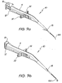
- Figures 9a, 9b and 9c show the device during the various stages of a surgical procedure.
- the plunger 18 is steadily moved towards the proximal end 12 of the housing 11 until it abuts with the proximal end 12 and cannot be moved any further.
- the movement of the plunger 18 advances the electrode array 100 from the distal end 13 of the housing 11.
- the electrode array 100 advances off the straightening member and from the housing 11, whereupon it takes on a pre-determined curved configuration.
- the finger rests 32 may then be drawn back towards the proximal end 12 of the housing 11 such that the straightening member 101 is fully removed from the electrode array 100.
- a cartridge member as defined in the third aspect of the invention is generally depicted as 129 in the accompanying drawings.
- the cartridge member 129 is shown when used with electrode array 100 which has straightening member 101 extending therefrom.
- the cartridge member 129 includes an elongate body 130 which extends from a first end 131 to a second end 132.
- the elongate body 130 has an internal lumen 133 which extends therethrough and which is adapted to receive the electrode array 100.
- the cartridge member 129 further includes a slot 134 along a portion of the length of the elongate body to accommodate the electrical leads of the electrode array 100 and a window 135 in a portion of the sidewall of the elongate body 130 adjacent the first end 131.
- the window 135 5 enables a user to view a portion of the electrode array 100 which is positioned within the lumen 133 of the cartridge member 129.
- the electrode array 100 is loaded onto the cartridge member 129 by feeding the engagement portion 103 of the straightening member 101 of the electrode array 100 into the second end 132 of the cartridge member.
- the electrode array 100 is oriented such that the electrical leads of the electrode array 100 are substantially aligned with the slot 134 along the elongate body 130 of the cartridge member 129.
- the electrode array 100 is then guided into the cartridge member 129 by pulling lightly on the electrical leads of the electrode array 100 until the ball 104 and loop 105 extend from the first end 131 of the cartridge member 129.
- the cartridge member 129 and electrode array 100 may be used with device 10 as depicted in Figures 10b and 10c .
- the cartridge member 129 is loaded onto the distal end 13 of the housing 11 and the electrode array positioning member 14 of the device 10 caused to engage the electrode array 100 within the cartridge member 129.
- a portion of the housing 11 adjacent the distal end 13 includes a window 46.
- the window 135 5 of the cartridge member 129 is aligned with the window 46 in the housing 11 of the device 10.
- Figures 11a to 11d show a further embodiment of device 10 of the present invention wherein the electrode array positioning member 14 comprises an elongate member extending from first end 15 to second end 16. Second end 16 is forked to maximise engagement with electrode array 100.
- the positioning member includes a plunger 18 at its first end 15. Movement of the plunger 18 in the direction shown by the arrow in Figure 11d causes the electrode array 100 to move from the distal end of the housing 11 and into a cochlea of a patient.
- the capture member 17 of this embodiment comprises a tie member 150 which is anchored at one end 151 to an anchor 152 located on a wall of the housing 11. At its second end 153 the tie member 150 engages the engagement portion 103 of straightening member 101. In this case, the tie member forms a loop at the second end 153 to engage a complementary part of the engagement portion.
- the engagement portion 103 of the straightening member is held by the tie member 150 and thus the electrode array 100 advances off the straightening member 101.
- This embodiment has a number of safety features including a cochleostomy stopper 154 positioned adjacent the distal end 13 of the housing 11. During an insertion procedure, the cochleostomy stopper 154 abuts with an edge of a cochleostomy such that the housing 11 is prevented from advancing too far into a cochlea of a subject.
- the electrode array positioning member 14 includes a second stopper 155 located at a position along its length. The second stopper 155 abuts with a portion of the housing 11 such that the electrode array positioning member 14 is prevented from moving any further in a direction towards the distal end 13 of the housing 11.
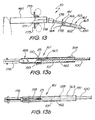
- FIG. 12 A further embodiment of device 10 is depicted in Figures 12, 12a, 12b , 13, 13a and 13b .
- the housing 11 comprises a handle 160 and a tip member 161.
- the tip member 161 includes the electrode array positioning member 14 which comprises an inner member 162 which is slidably receivable within an outer member 163.
- the inner member 162 comprises an elongate tubular structure extending from a first end 164 connected to the handle 160 to a second end 165 adapted to receive electrode array 100.
- the tubular structure of the inner member 162 defines an internal lumen 159 extending therethrough.
- the outer member 163 also comprises a tubular structure defining an internal lumen 170.
- the outer member 163 extends from a proximal end 166 relatively adjacent the handle 160 to a distal end 167 relatively distal the handle 160.
- the outer member 163 further includes capture member 17 positioned along the length of the outer member 163.
- the handle 160 comprises a plunger member 168 which, when the device is in use, is moved forward relative to the outer member 163 and in a direction towards the cochlea (not depicted) of the subject.
- a plunger member 168 which, when the device is in use, is moved forward relative to the outer member 163 and in a direction towards the cochlea (not depicted) of the subject.
- the inner member 162 As the inner member 162 is connected to the handle 160, such movement causes the inner member 162 to move longitudinally forward relative to the outer member 163 until at least part of the inner member extends beyond the distal end 167 of the outer member 163. This action advances the electrode array 100 forward of the outer member 163 and into the cochlea.
- the outer member 163 includes a cochleostomy stopper 154 as depicted in Figures 12a and 13a .
- the cochleostomy stopper 154 is located adjacent the distal end 167 of the outer member 163.
- the cochleostomy stopper 154 abuts with the edge of a cochleostomy (not shown) thereby preventing the outer member 163 from moving into the cochlea.
- the outer member 163 is substantially fixed in a position and cannot move further into the cochlea during use of the device 10.
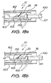
- the capture member 17 comprises a flap member 25 as depicted in Figures 12a, 12b , 13a and 13b .
- the flap member 25 extends from a wall 169 of the outer member into the lumen 170 of the tubular outer member 163 and through a slot 158 in the a wall of the inner member 162 such that it extends into lumen 159 of the inner member 162.
- the engagement portion 103 of the straightening member 101 of the electrode array 100 is depicted as a loop 105 which is engaged by flap member 25.
- the device 10 may further include a tie line 171.
- the tie line 171 is connected at a first end 172 to an actuator member 173 located on handle 160. At a second end 174, the tie line 171 is connected to loop 105 of straightening member 101.
- the tie line 171 is a flexible cord made from a suture-type material. Such material has the advantage that it is biocompatible.
- the actuator member 173 is a sliding means 175 which is movable along a length of the handle 160.
- the tie line 171 is pulled taut such that the straightening member 101 together with the outer member 163 (as the outer member is in engagement with the straightening member via the capture member) are pulled away from a cochleostomy thereby fully withdrawing the straightening member 101 from the electrode array 100.
- the device 10 includes a pulling rod 176 which is connected at one end 177 to the sliding means 175 and connected at a second end 178 to the proximal end 166 of the outer member 163. Movement of the sliding means 175 in a direction away from a surgical site causes the outer member 163 to withdraw from the cochleostomy site. As the capture member 17 of the outer member 163 is in engagement with engagement portion 103 of straightening member 101, movement of the sliding means 175 in this manner fully withdraws the straightening member 101 from the electrode array 100.
- the outer member 163 comprises the electrode array positioning member 14 which is connected to plunger member 168.
- the inner member 162 includes the capture member 17 ie flap member 25 on a wall of the inner member and extending into lumen 159 of inner member 162.
- Movement of plunger member 168 causes movement of the outer member 163 relatively towards a surgical site such that the electrode array 100 is advanced into a cochlea of a subject.
- the outer member 163 may be directly connected to the handle 160 as depicted in Figure 14 or, alternatively connected to the handle by a piston member 180 as depicted in Figures 15, 15a and 15b .
- the pulling rod 176 is connected at its second end 174 to the first end 164 of the inner member 162. Movement of the sliding means 175 in a direction away from a surgical site causes the inner member to move away from the surgical site thereby fully withdrawing the straightening member 101 from the electrode array 100.
- the device shown in Figures 17 and 17a, b and c has a housing 11 which comprises an inner member 162 and an outer member 163.
- the inner member is received within lumen 170 of the outer member 163.
- the electrode array positioning member 14 in this embodiment may be seen as an elongate pushing rod 190 which extends through lumen 159 of inner member 162, along a substantially length of the inner member 162.
- the inner member 162 includes the capture member which typically comprises flap member 25 extending from a wall of the inner member 162 and into the lumen 159 of inner member 162.
- the capture member engages engagement portion 103 of the straightening member which extends into the lumen 159 at the second end 165 of the inner member 162 when an electrode array is loaded onto the device.
- the electrode array is advanced into the cochlea 300 during a procedure by pushing plunger 18.
- the inner member 162 is held in a relatively fixed manner such that it cannot move in said forward direction.
- the electrode array 100 therefore advances off the straightening member 101.
- the electrode array positioning member 14 may include an actuator member 191.
- the actuator member 191 extends from the elongate pushing rod 190 and through slots in the walls of the both the inner member 162 and the outer member 163. The actuator member 191 may be moved along said slots to actuate movement of the electrode array positioning member 14.
- the second end 16 of the electrode array positioning member 14 includes a recessed portion 192 to accommodate engagement portion 103 of the straightening member 101.
- the electrode array loaded on the device 10 may be moved by pushing the pushing rod against a proximal end 200 of the electrode array rather than pushing against engagement portion 103. This prevents damage to the engagement portion 103 which is housed in said recessed portion 192.
- FIGS 19, 19a and 19b show how the elongate pushing rod 192 may be moved by movement of the actuator member 191. Rather than being connected to or forming part of the elongate pushing rod 190, the actuator member is brought into engagement with a proximal end 193 of the pushing rod 190.
- the actuator member is a slide which may move along slots in the inner and the outer members.
- the actuator member 191 further includes an extension member 194.
- the extension member 194 When the pushing rod 190 is in its second position, the extension member 194 abuts with a wedge 195 that inwardly extends from a wall of the inner member 162 and into lumen 159 of inner member 162.
- the extension member 194 is relatively rigid in structure and when the actuator member 191 is withdrawn from the surgical site, the extension member 194 exerts pressure on the wedge member 195 thereby causing the inner member 162 to also move in a direction away from the surgical site.
- the inner member 162 includes the capture member 17, such movement allows full withdrawal of the straightening member 101 of an electrode array 100.
- the capture member 17 includes a pair of jaw members 200 at its capture end 24.
- the jaw members 200 are made from a suitably malleable material to allow movement of said jaw members 200 from a first open position(shown in Figure 20 ) to a second closed position (shown in Figure 20a ).
- the jaw members 200 are moved to their closed position by movement of the electrode array positioning member 14 which in this embodiment comprises inner member 162.
- the jaw members 200 may be held by elongate member 201 which extends through lumen 159 of inner member 162.
- the jaw members 200 extend from the second end 165 of the inner member 162 and flare outwardly from said second end 165. Movement of the inner member 162 by actuator member 191 causes the second end 165 of the inner member 162 to abut with the flared out jaw members 200.
- the continued force applied to the jaw members 200 as the inner member 162 moves from its first to its second position causes said jaw members 200 to deform and take on their second closed position thereby capturing the engagement portion 103 of the straightening member of an electrode array 100 loaded onto the device 10.
- the capture member is prevented from moving in the direction of the inner member 162 by stopper member 204 which abuts with a shoulder 205 of a recessed section 206 of the capture member 17.
- the capture member 17 of this embodiment further includes a latch member 202 which engages actuator member 191 when the inner member 162 is in its second position.
- a latch member 202 which engages actuator member 191 when the inner member 162 is in its second position.
- the device 10 includes a safety clip 210 which is depicted in Figure 21 , and when used with the device 10 in Figures 22a, b and c .
- the safety clip 210 prevents premature movement of the electrode array positioning member 14 and thus movement of the electrode array 100.
- the safety clip 210 is clipped onto a region of the electrode array positioning member 14 adjacent its first end 15. In the embodiment depicted, a region of the electrode array positioning member 14 adjacent said first end 15 extends beyond the proximal end 12 of the housing 11. Movement of the first end 15 of the electrode array positioning member towards the proximal end 12 of the housing allows the electrode array 100 to advance off straightening member 101 and into a cochlea of a subject. The safety clip 210 abuts with the proximal end 12 of the housing 11 thereby preventing any such forward movement of the electrode array positioning member 14.
Landscapes
- Health & Medical Sciences (AREA)
- Life Sciences & Earth Sciences (AREA)
- Public Health (AREA)
- General Health & Medical Sciences (AREA)
- Engineering & Computer Science (AREA)
- Biomedical Technology (AREA)
- Heart & Thoracic Surgery (AREA)
- Veterinary Medicine (AREA)
- Animal Behavior & Ethology (AREA)
- Nuclear Medicine, Radiotherapy & Molecular Imaging (AREA)
- Surgery (AREA)
- Otolaryngology (AREA)
- Cardiology (AREA)
- Radiology & Medical Imaging (AREA)
- Pathology (AREA)
- Medical Informatics (AREA)
- Molecular Biology (AREA)
- Acoustics & Sound (AREA)
- Physics & Mathematics (AREA)
- Biophysics (AREA)
- Psychology (AREA)
- Vascular Medicine (AREA)
- Electrotherapy Devices (AREA)
- Surgical Instruments (AREA)
- Prostheses (AREA)
- Battery Electrode And Active Subsutance (AREA)
Abstract
Description
- The present invention relates to a device, method and system for the insertion of an electrode array into a cochlea of a subject and the simultaneous removal of a straightening means of the electrode array.
- In many people who are profoundly deaf, the reason for deafness is absence of, or destruction of, the hair cells in the cochlea which transduce acoustic signals into nerve impulses. These people are unable to derive suitable benefit from conventional hearing aid systems, no matter how loud the acoustic stimulus is made, because there is damage to or absence of the mechanism for nerve impulses to be generated from sound in the normal manner.
- It is for this purpose that cochlear implant systems have been developed. Such systems bypass the hair cells in the cochlea and directly deliver electrical stimulation to the auditory nerve fibres, thereby allowing the brain to perceive a hearing sensation resembling the natural hearing sensation normally delivered to the auditory nerve.
US Patent 4532930 provides a description of one type of traditional cochlear implant system. - Typically, cochlear implant systems have consisted of essentially two components, an external component commonly referred to as a processor unit and an internal implanted component commonly referred to as a stimulator/receiver unit. Traditionally, both of these components have cooperated together to provide the sound sensation to a user.
- The external component has traditionally consisted of a microphone for detecting sounds, such as speech and environmental sounds, a speech processor that converts the detected sounds, particularly speech, into a coded signal, a power source such as a battery, and an external transmitter coil.
- The coded signal output by the speech processor is transmitted transcutaneously to the implanted stimulator/receiver unit situated within a recess of the temporal bone of the user. This transcutaneous transmission occurs via the external transmitter coil which is positioned to communicate with an implanted receiver coil provided with the stimulator/receiver unit.
- This communication serves two essential purposes, firstly to transcutaneously transmit the coded sound signal and secondly to provide power to the implanted stimulator/receiver unit. Conventionally, this link has been in the form of a radio frequency (RF) link, but other such links have been proposed and implemented with varying degrees of success.
- The implanted stimulator/receiver unit traditionally includes a receiver coil that receives the coded signal and power from the external processor component, and a stimulator that processes the coded signal and outputs a stimulation signal to an intracochlear electrode assembly which applies the electrical stimulation directly to the auditory nerve producing a hearing sensation corresponding to the original detected sound.
- Traditionally, the external componentry has been carried on the body of the user, such as in a pocket of the users' clothing, a belt pouch or in a harness, while the microphone has been mounted on a clip behind the ear or on the lapel of the user.
- More recently, due in the main to improvements in technology, the physical dimensions of the speech processor have been able to be reduced allowing for the external componentry to be housed in a small unit capable of being worn behind the ear of the user. This unit allows the microphone, power unit and the speech processor to be housed in a single unit capable of being discretely worn behind the ear, with the external transmitter coil still positioned on the side of the user's head to allow for the transmission of the coded sound signal from the speech processor and power to the implanted stimulator unit.
- Together with improvements in available technology, much research has been undertaken in the area of understanding the way sound is naturally processed by the human auditory system. With such an increased understanding of how the cochlea naturally processes sounds of varying frequency and magnitude, there is a need to provide an improved cochlear implant system that delivers electrical stimulation to the auditory nerve in a way that takes into account the natural characteristics of the cochlea.
- It is known in the art that the cochlea is tonotopically mapped. In other words, the cochlea can be partitioned into regions, with each region being responsive to signals in a particular frequency range. This property of the cochlea is exploited by providing the electrode assembly with an array of electrodes, each electrode being arranged and constructed to deliver a cochlea stimulating signal within a preselected frequency range to the appropriate cochlea region. The electrical currents and electric fields from each electrode stimulate the nerves disposed on the modiola of the cochlea.
- It has been found that in order for these electrodes to be effective, the magnitude of the currents flowing from these electrodes and the intensity of the corresponding electric fields, are a function of the distance between the electrodes and the modiola. If this distance is relatively great, the threshold current magnitude must be larger than if the distance is relatively small. Moreover, the current from each electrode may flow in all directions, and the electrical fields corresponding to adjacent electrodes may overlap, thereby causing cross-electrode interference. In order to reduce the threshold stimulation amplitude and to eliminate cross-electrode interference, it is advisable to keep the distance between the electrode array and the modiola as small as possible. This is best accomplished by providing the electrode array in the shape which generally follows the shape of the modiola. Also, this way the delivery of the electrical stimulation to the auditory nerve is most effective as the electrode contacts are as close to the auditory nerves that are particularly responsive to selected pitches of sound waves.
- In order to achieve this electrode array position close to the inside wall of the cochlea, the electrode needs to be designed in such a way that it assumes this position upon or immediately following insertion into the cochlea. This is a challenge as the array needs to be shaped such that it assumes a curved shape to conform with the natural shape of the inside wall of the cochlea and must also be shaped such that the insertion process causes minimal trauma to the sensitive structures of the cochlea. In this sense, it is desirable that the electrode array is held in a generally straight configuration at least during the initial stages of the insertion procedure.
- Several procedures have been adopted to provide for an electrode assembly that is relatively straightforward to insert while adopting a curved configuration following insertion in the cochlea. In this regard, it is known to make an electrode array that includes a spiral-shaped carrier which has a natural spiral shape generally conforming to the configuration of a cochlea. Such an array may also include a straightening element or stylet to enable the carrier to be maintained in a straight configuration for insertion. The straightening member is then typically removed from the carrier following insertion thereby allowing the carrier to take on its natural spiral-shape and assume a position adjacent the inner wall of the cochlea. Such a configuration is described in the Applicant's
issued US Patent 6,421,569 . - Typically, the straightening member is removed following the insertion of the electrode array into the cochlea by clamping an exposed end of the straightening member with tweezers and gradually removing the stylet. This technique is difficult to coordinate and requires both hands of a surgeon to perform.
- Document
US-A-6 149 657 discloses a device as described in the preamble ofclaim 1. - One problem with such a technique is that it is difficult to control the insertion process so that damage to the sensitive structures of the cochlea can be avoided. This is due to the fact that the cochlea has a natural spiral shape and the insertion of a substantially straight electrode array into such a space will cause the array to impact upon the walls of the cochlea, increasing the risk for damage to the cochlea walls if due care is not taken. It is typically not until the electrode array is fully inserted that the transition of the array from substantially straight to spirally curved is affected, hence the change transition does not aid in the insertion process as such.
- A number of tools have been developed to assist in the insertion of the electrode array and subsequent removal of the straightening element. Typically, such devices have been difficult to use and have required complex sliding mechanisms to achieve the desired result. This has resulted in tools that are difficult to manufacture, difficult to clean for re-use, have an increased probability of failure due to their complexity, and which have not been specifically designed to control the shape transition of the electrode array to aid in a non-traumatic insertion procedure.
- The present invention is directed to an insertion tool for an electrode assembly which is constructed to address the abovementioned problems of prior devices.
- Any discussion of documents, acts, materials, devices, articles or the like which has been included in the present specification is solely for the purpose of providing a context for the present invention. It is not to be taken as an admission that any or all of these matters form part of the prior art base or were common general knowledge in the field relevant to the present invention as it existed before the priority date of each claim of this application.
- Throughout this specification the word "comprise", or variations such as "comprises" or "comprising", will be understood to imply the inclusion of a stated element, integer or step, or group of elements, integers or steps, but not the exclusion of any other element, integer or step, or group of elements, integers or steps.
- The present invention provides a device as set forth in
claim 1, and a method of using this device as set forth inclaim 46. - In a preferred embodiment, the electrode array is configured to be implanted in a cochlea of a subject.
- The housing may include a handle and a tip member wherein the handle and tip member may be integral with one another or alternatively, the tip may be removably connected to the handle. The housing may also include an inner member positioned at least partially within an outer member.
- The electrode array positioning member may comprise a number of structures and may be moved from its first position to its second position by a number of means. In each embodiment discussed below, it may be seen that movement of the electrode array positioning member in a direction towards the distal end of the housing relative to a substantially fixed capture member allows the electrode array which has been loaded onto the device to effectively "advance off' the straightening member.
- In a preferred embodiment, said electrode array positioning member comprises an elongate member that substantially extends through said housing from a first end to a second end, said second end adapted to engage part of the electrode array.
- With reference to movement of the electrode array positioning member, the electrode array positioning member may be connected to the handle of the housing such that as the handle is moved in a direction towards the distal end of the housing, said electrode array positioning member is also moved in said direction. In use, this embodiment enables a surgeon to manipulate the device of the present invention much like a pen.
- Alternatively, the electrode array positioning member may comprise a plunger member. In this embodiment, it is preferred that a length of the electrode array positioning member adjacent the first end of the electrode array positioning member extends beyond the proximal end of the housing. When the device is in use, the surgeon may exert pressure on the plunger member to cause movement from its first position to its second position. The plunger member typically includes an actuator member at its first end wherein said actuator member, which may be a thumb rest, is adapted to abut with the proximal end of the housing. This abutment limits movement of the electrode array positioning member towards the distal end of the housing thus ensuring that a user does not advance an electrode array too far into a cochlea of a subject.
- Still further, the electrode array positioning member may be connected to or brought into engagement with a slider such that movement of the slider towards the distal end of the housing causes movement of said electrode array positioning member in said direction. The slider may move along a slot in the wall of the housing and include finger rests to enable a user to move the slider along said slot.
- The second end of the electrode array positioning member may be forked, grooved or slotted to optimise engagement with the electrode array.
- Alternatively, at least a portion of the electrode array positioning member adjacent the second end may comprise a substantially hollow cylinder defining an internal lumen therein. In this regard, it is preferred that in addition to being adapted to engage and position an electrode array, the lumen of the electrode array positioning member also receives an engagement portion of the straightening member of the electrode array.
- Similarly, the electrode array positioning member may include a grooved or recessed portion at or adjacent its second end to receive the engagement portion of the straightening member.
- In another embodiment, the housing may include an inner member and an outer member. The inner member and the outer member typically make up part of the tip member of the housing and are configured such that one of said inner member or outer member is fixed relative to the other member such that the relatively "movable" member may include the electrode array positioning member and the substantially "fixed" member may include the capture member.
- The capture member may include a number of structures but in each embodiment has the feature that it engages and "captures" the engagement portion of the straightening member such that as the electrode array is advanced into a cochlea of a subject during a procedure, the engagement portion of the straightening member is held by the capture member and the electrode array is allowed to "advance off" the straightening member. In this regard, the capture member may be essentially fixed relative to the electrode array positioning member.
- By the term "substantially fixed", it is considered that the capture member does not substantially move in a direction towards the distal end of the housing of the device, which, when the device is in use, is towards a cochlea of a subject. It is envisaged, however, that the capture member may be moved relatively in a direction away from the distal end of the housing such that the straightening member of the electrode array may be fully removed from an electrode array.
- In a preferred embodiment, the capture member may comprise an elongate member which extends from one end to a capture end. At or adjacent the capture end said capture member may include a flap, hook, loop or tie or any member capable of engaging with the engagement portion of the straightening member when said electrode array is loaded onto the device of the present invention.
- Alternatively, the capture end may include a pair of jaw members which are movable from a first open position to a second closed position such that in the second closed position, the jaw members clamp around the engagement portion of the straightening member.
- Rather than an elongate member extending through the main body, the capture member may include a member positioned on or forming part of a wall of the housing. For instance, in the embodiment having a tip member which comprises an inner member and an outer member, the capture member may be positioned on one of said inner or outer members. As discussed above, one of the inner member or the outer member is movable relative to the other that is substantially fixed. The capture member may be positioned on said substantially fixed member. The capture member may include a flap, hook, loop or tie or any member capable of engaging with the engagement portion of the straightening member.
- It is also preferred that at least a portion of the electrode array positioning member adjacent its second end includes a slot along its wall. Said slotted portion may receive at least part of the capture member.
- In the embodiment wherein the electrode array positioning member is an elongate structure extending from a first end to a second end and the capture member also comprises an elongate structure extending from one end to a capture end, it is envisaged that the capture end of the capture member may comprise a substantially hollow cylinder. The second end or a portion adjacent the second end of the electrode array positioning member is receivable within a lumen formed by the substantially hollow cylinder of the capture member. The flap, hook, loop or tie member of the capture member preferably extends inwardly of the capture end such that it may engage the engagement portion of the straightening member received by the electrode array positioning member.
- In the embodiment wherein the capture member is positioned on a wall of an inner member or an outer member of the tip member of the housing, it is preferred that the inner member and the outer member are substantially hollow in structure such that the inner member is slidably receivable within the outer member.
- In one embodiment, the electrode array positioning member may comprise the inner member. In this embodiment, the capture member is positioned on the outer member such that at least part of the capture member extends through the slotted portion of the electrode array positioning member.
- In another embodiment, the electrode array positioning member may comprise the outer member and the inner member includes the capture member. In this embodiment, the electrode array may be received within both the inner and the outer members such that the engagement portion of the straightening member of the electrode array expends into the lumen of the inner member and engages with the capture member. The outer member engages the electrode array such that as the outer member is moved so too is the electrode array.
- The capture member preferably includes a flap member made from a resiliently flexible material such as a plastics material. In this embodiment, the principle of capture of the engagement portion of the straightening member of the electrode array relies upon movement or deformation of the flap member caused by movement of the engagement portion through the lumen of the electrode array positioning member as the electrode array is loaded onto the device of the invention. In this regard, the force of the moving engagement portion of the straightening member against the flap member causes the flap member to move from a first position substantially occluding the lumen of the electrode array positioning member to a second position which allows passage of the engagement portion of the straightening member past the flap member. Upon release of the "deforming" force, ie. once the engagement portion has passed the flap member, said flap member may return to its original configuration such that it substantially occludes the lumen of the electrode array positioning member and prevents the engagement portion from moving in a reverse direction. This may be achieved in a number of ways as discussed in further detail below.
- Alternatively, the capture member may include a hook, press stud, or other like member that extends from the capture member and into the lumen of the electrode array positioning member whereupon it engages a complementary structure such as a loop member comprising the engagement portion of the straightening member.
- In the embodiment wherein the capture member includes a pair of jaw members at its capture end, it is envisaged that the jaw members are made from a suitably malleable material to allow movement of said jaw members from a first open position to a second closed position. In one embodiment, the jaw members may be moved to their closed position by movement of the electrode array positioning member. In this regard, the capture member may be positioned within at least the substantially hollow cylinder of the second end of the electrode array positioning member such that the jaw members extend beyond the second end and flare outwardly from said second end. Movement of the electrode array positioning member to its second position causes the second end of the electrode array positioning member to abut with the flared out jaw members. The continued force applied to the jaw members as the electrode array positioning member moves from its first to its second position causes said jaw members to deform and take on their second closed position thereby capturing the engagement portion of the straightening member of an electrode array loaded onto the device.
- The straightening member of the electrode array typically extends through a central lumen or along a slot in the electrode array from a proximal end of said electrode array to a leading tip of the electrode array. The straightening member acts to straighten a pre-curved electrode array thus enabling insertion of the electrode array through a cochleostomy and into the cochlea.
- Typically, said engagement portion of the straightening member which is captured by the capture member extends beyond the proximal end of the electrode array and may include a number of structures including but not limited to a substantially spherical member, a hemispherical member, a conical member, a bullet-like member, or an arrow-shaped member. Alternatively, as mentioned above, the engagement portion may include a loop or other like structure or a combination of a loop with any one of the substantially spherical, hemispherical, conical, bullet-like, or arrow-shaped members. In this latter embodiment, it is preferred that the loop is located furthest from the electrode array than either the substantially spherical, hemispherical, conical, bullet-like, or arrow-shaped member. This has the advantage that a surgeon may maintain the option of inserting the electrode array manually wherein the loop may be more easily captured by a hand tool such as a hook, forceps, tweezers or the like.
- In a further embodiment, the engagement portion of the straightening member may comprise a structure such as a substantially spherical, hemispherical, conical, bullet-like, or arrow-shaped member having an aperture therein such that said aperture may act as a means of manual capture of the straightening member and the substantially spherical, hemispherical, conical, bullet-like, or arrow-shaped member as a means of deforming the flap member and resulting in capture of the engagement portion of the straightening member.
- In one embodiment, the electrode array may be loaded into a cartridge member with the engagement portion of the straightening member extending from one end of the cartridge member. The end of the cartridge member with the engagement portion of the straightening member extending therefrom is received within the distal end of the housing of the device. As the cartridge member is loaded onto said distal end, said portion of the straightening device may be caused to move through the lumen of the substantially hollow portion of the electrode array positioning member and along the slotted portion of the electrode array positioning member.
- As discussed above, at least part of the capture member may extend into the slot formed in the wall of said slotted portion. Where the capture member includes a flap member, the flap member typically extends into and substantially occludes the lumen of the hollow cylinder of the electrode array positioning member. In the embodiment wherein the flap member is made from a resiliently flexible material, as the engagement portion of the straightening member is moved into and along the slotted portion of the electrode array positioning member, the engagement portion of the straightening member is forced against the flap member causing said flap member to move or deform such that it no longer substantially occludes the lumen of the electrode array positioning member. This allows the engagement portion of the straightening member to pass the flap member. Once the engagement portion of the straightening member has moved beyond the flap member, the flap member may resume its original configuration extending through the slot of the slotted portion of the electrode array positioning member and into the lumen of the electrode array positioning member and substantially occluding said lumen.
- Typically, the flap member may only be movable or deformable in one direction to allow the engagement portion of the straightening member to pass. The flap member therefore acts as a "one-way gate" for the engagement portion of the straightening member.
- In a preferred embodiment, when the electrode array is loaded onto the device, the second end of the electrode array positioning member abuts with the proximal end of the electrode array. In the embodiment wherein the electrode array positioning member comprises a plunger member, when the plunger member is moved in a direction towards the distal end of the housing, the second end of the electrode array positioning member pushes the proximal end of the electrode array such that the electrode array is advanced from the distal end of the housing, and when used in a surgical procedure, advanced into a cochlea of a subject.
- As the electrode array is advanced into the cochlea, the engagement portion of the straightening member captured by the flap member is held by the "one way gate" system of the flap member and thus prevented from advancing with the electrode array. The entire straightening member is, therefore, prevented from advancing into the cochlea with the electrode array and the electrode array "advances off" the straightening member and into the cochlea. Substantially free of the straightening member, the electrode array may then start to take on a pre-curved configuration within the cochlea of the subject.
- To fully remove the straightening member from the electrode array, the capture member may be moved in a direction towards the proximal end of the housing. Where the capture member includes a flap member, such movement causes the flap member to abut with part of the engagement portion of the straightening member and pull the engagement portion of the straightening member along the slotted portion of the electrode array positioning member in a direction towards the proximal end of the housing.
- In this regard, the capture member may be connected to a slide member which may be positioned on an outer wall of the housing or, alternatively, within the housing and having a portion extending from the housing to enable manipulation of said slide member by a user. The capture member may be connected to said slide member by a number of means including by a tie member or, alternatively, by a pulling rod. The slide member typically includes two fingers rests which extend from said slide member and through two opposing slots in the wall of the housing. A user may therefore move the finger rests along the slots of the housing to effect movement of the capture member. Movement of the finger rests in a direction towards the proximal end of the housing typically effects full withdrawal of the straightening member from the electrode array.
- The device of the present invention may further comprise a safety mechanism to prevent withdrawal of the straightening member before the electrode array positioning member has moved to its second position and the electrode array advanced into the cochlea of a subject. In this regard, typically, the slide member has a spring member housed in a recess of said slide member. The spring member is preferably made from a resiliently flexible material and includes a main body which, on one side is hingedly connected to a leg member. On an opposing side of the main body, the spring member includes a housing engagement portion which extends from the main body and into a niche in the inner wall of the housing of the device. When the housing engagement portion is positioned within the niche of the housing, any movement of the spring member and the slide member relatively towards or away from the distal end of the housing is prevented.
- The slide member and the main body of the spring member may further include a groove which receives a portion of the electrode array positioning member thereby allowing the electrode array positioning member to pass through the groove of the slide member as the electrode array positioning member is moved from its first to its second position.
- Typically, the electrode array positioning member comprises a number of components connected to or integral with one another. Preferably, the electrode array positioning member includes a plunger member made up of a thumb rest connected to or integral with a pushing arm. The thumb rest and pushing arm are preferably made from a relatively hard material such as a hard plastics material. The pushing arm may be connected to or integral with an intermediate member which is typically made from a relatively more flexible material than the thumb rest and pushing arm. Further, the intermediate member can have a smaller cross-sectional diameter than the pushing arm. Finally, the intermediate member is connected to or integral with an end member which receives the electrode array. The end member is typically made from a suitably biocompatible material such as surgical stainless steel or titanium.
- Preferably, a portion of the pushing arm adjacent its connection with the intermediate member is tapered to form a shoulder.
- In use, the intermediate member typically passes along the groove of the slide and spring member when the plunger is actuated and the electrode array is advanced into a cochlea. Movement of the intermediate member along the groove of the spring member does not disrupt the configuration of the resiliently flexible spring member. Accordingly, if the spring member is positioned such that the housing engagement member is within the niche in the housing, movement of the intermediate member of the electrode array positioning member along the groove does not dislodge said housing engagement member and the spring member, slide member and the capture member (which is connected to the slide member) are therefore prevented from moving either in a direction relatively towards or away from the distal end of the housing, that is, each of these components are fixed relative to the housing and the electrode array positioning member. This enables the electrode array positioning member to be moved to its second position without the risk of the straightening member of the electrode array being withdrawn prematurely from said array.
- As the electrode array positioning member reaches its second position, the tapered portion of the pushing arm extends into the groove in the spring member. The shoulder of the pushing arm pushes against a wall of the groove of the main body, causing the main body to move about its hinged joint with the leg member from a first position wherein the main body is relatively spaced from the leg member to a second position wherein said main body is relatively less spaced from the leg member. The leg member is substantially prevented from moving relative to the main body as it is relatively securely housed within a complementary structure of the slide member. Movement of the main body of the spring member relative to the leg member disengages the housing engagement member from the niche in the inner wall of the housing. With the housing engagement member disengaged from the inner wall of the housing, the slide member and the capture member are free to be moved by way of the finger rests in a direction towards the proximal end of the housing.
- In a preferred embodiment, the distal end of the housing abuts with the cochlea during the entire procedure of insertion of the electrode array and removal of the straightening member from the electrode array. Such a device provides a stable tool for the insertion of the electrode array with less risk of slippage or accidental movement of the device during insertion of said array.
- In another embodiment, the device may include a safety mechanism to prevent the distal end of the housing advancing too far into a cochlea of a subject. For example the device may include a cochleostomy stopper at or adjacent the distal end which abuts with an edge of a cochleostomy.
- Other safety mechanisms include means to prevent the electrode array advancing too far into a cochlea of a subject. In this regard, the device may include at least one stopper member which prevents the electrode array positioning member from moving beyond a predetermined position. In one embodiment, the stopper member may include an engagement member which engages with a latch member when the electrode array positioning member is in its second position. Such engagement with said latch member prevents the electrode array positioning member moving any further beyond the second position. The latch member may be positioned on any part of the device including on a wall of the housing or may form part of the capture member.
- In another embodiment wherein the electrode array positioning member is moved by movement of a slider along a slotted length of the housing, the limiting factor in this case may be the length of a slot in the housing along which the slider may travel.
- Preferably, when the electrode array is loaded onto the device of the present invention, a portion of the electrode array extends a distance of approximately 7 to 10 mm from the distal end of the housing. In this embodiment, when the distal end of the housing is brought into abutment with a cochleostomy during a procedure, the leading tip of the electrode array is positioned in the middle of the lumen near the back of the basal turn of the scala tympani such that said leading tip of the electrode does not exert pressure on the surrounding tissue.
- As the electrode array is moved to its second position by movement of the electrode array positioning member, the electrode array continues to follow a trajectory along the middle of the lumen of the scala tympani thereby avoiding pressure on the lateral wall of the cochlea thus minimising the potential for trauma to the lateral wall and the modiolar wall.
- The device of the present invention may further include a means to release an electrode array loaded thereon. In this embodiment, the electrode array may be released by a surgeon should manual insertion be preferred.
- In another embodiment, the device of the present invention includes a safety clip member to prevent premature movement of the electrode array positioning member and thus movement of the electrode array. In this regard, it is envisaged that a surgeon would be required to release the safety clip prior to a surgical procedure.
- It is envisaged that the safety clip may be positioned in engagement with the electrode array positioning member at or adjacent its first end. The safety clip may further abut with a portion of the housing such that the electrode array positioning member is prevented from moving to its second position.
- Preferably, the safety clip is included in the packaging of the device to provide support during shipment and transportation. As a result, once unpacked, the device is in the correct position for an assembled cartridge and electrode array to be attached.
- The housing of the device may be made from a plastics material such as polytetrafluoroethylene (PTFE) or polypropylene. Alternatively, the housing may be made from a metal such as surgical steel, or a combination of metal and/or plastic. The choice of material may depend upon whether the device is manufactured as a re-usable or a disposable device.
- Typically, the housing is tapered towards the distal end. Further, it is preferred that the housing is angled in structure such as to provide a good line of vision for a surgeon during insertion of the electrode array. In this embodiment, the electrode array positioning member and the capture member may also be angled along their length to correspond with the angled structure of the housing. Preferably, the angle of the housing is in the region of 20 to 30°.
- Typically, the housing includes a handle and a tip member wherein the tip member is angled relative to the handle. As noted above, the tip member may be removably connected to the handle. Further, the tip member may be rotated relative to the handle such that rotational orientation of an electrode array loaded on the device may be set by a surgeon as desired or preferred for each surgery.
- Preferably, a region of the housing adjacent the distal end includes a window to allow a user to view the electrode array during loading of the electrode array onto the device.
- In a preferred embodiment, if the electrode array is loaded correctly, the user should be able to view the engagement portion of the straightening member of the electrode array which is captured by the capture member through the window.
- The electrode array may be mounted on the device during the manufacture of the device. Typically, however, the electrode array is mounted on the device by a surgeon, immediately prior to surgery.
- The device of the present invention further comprises a cartridge member for an electrode array, said electrode array having a straightening member, the cartridge member including an elongate body extending from a first end to a second end, said elongate body having an internal lumen extending therethrough which is adapted to receive the electrode array; the cartridge member further including a window in a portion of the sidewall of the elongate body adjacent the first end wherein said window enables a user to view a portion of the electrode array.
- The electrode array may be loaded onto the cartridge member by feeding a portion of the straightening member of the electrode array which extends from said electrode array into the second end of the cartridge member.
- The elongate body further includes a slot along at least a portion of its length to accommodate the leads of the electrode array. Preferably, the slot is substantially straight and constant in width as it extends along said at least a portion of the elongate body.
- The electrode array is preferably oriented such that the electrical leads of the electrode array are substantially aligned with said slot of the cartridge member. The electrode array may then be guided into the cartridge member by pulling lightly on the electrical leads of the electrode array until the portion of the straightening member which extends from the electrode array also extends from the first end of the cartridge member.
- The cartridge member and electrode array may be used with the device disclosed in the first aspect of the invention wherein the cartridge member may be loaded onto the distal end of the housing of the device and the electrode array positioning member of the device caused to engage the electrode array within the cartridge member. The cartridge may come pre-loaded with the electrode array or, alternatively, a surgeon may load the electrode array onto the cartridge prior to a procedure.
- In a preferred embodiment, a portion of the housing adjacent the distal end of the housing of the device includes a window. In this embodiment, as the cartridge member is loaded onto the device of the first aspect, the window of the cartridge member is aligned with the window in the housing of the device.
- Typically, if the engagement portion of the straightening member can be seen through the window of the housing, the cartridge member and electrode array may be taken to be correctly mounted and a user may then commence with the surgical procedure.
- In a preferred embodiment, the cartridge may be made from a number of materials and is preferably made from an electrically insulating material. Preferably, if not made of such a material, the cartridge includes an electrically insulating layer between the elongate body of the cartridge member and the electrode array. In this embodiment, a metal cartridge member may be coated on an inner wall defining the lumen of the main body with, for example, Paralyne™, PTFE, a lubricious silicone, or a plastic paint such as ABS.
- The device of the present invention further provides an electrode array, the electrode array including an elongate body which extends from a proximal end to a distal end and a straightening member extending along at least part of the length of the elongate body wherein at least a portion of the straightening member extends beyond the proximal end of the elongate body, said at least a portion including a substantially spherical member, a substantially hemispherical member or an arrow-shaped member.
-
-
Figure 1 is a schematic view of a fully assembled device according to a preferred embodiment of the present invention; -
Figure 2 is a schematic view of the partially assembled device ofFigure 1 ; -
Figures 3a and 3b are schematic views of part of the electrode array positioning member of the device shown inFigure 1 ; -
Figure 4 is a further schematic view of the partially assembled device ofFigure 1 ; -
Figure 5 shows schematic views of part of the capture member of the device ofFigure 1 ; -
Figures 6a-6f and 6j show part of a straightening member of an electrode array; -
Figures 6g, 6h, and 6i depict part of the straightening member being captured by an embodiment of a capture member of the device of the present invention; -
Figure 7 is a view through a window of the device depicted inFigure 1 ; -
Figure 8 is a further schematic part view of the device ofFigure 1 ; -
Figures 9a, 9b and9c show the device ofFigure 1 during the various stages of insertion of an electrode array; -
Figures 10a, 10b and 10c show a cartridge member according to another aspect of the invention; and -
Figures 11a to 22c depict further embodiments of the device of the present invention. - A device of one embodiment of the present invention is generally depicted as 10 in the accompanying drawings. The
device 10 is used for inserting anelectrode array 100 into a cochlea of a subject and removing a straighteningmember 101 of theelectrode array 100. - The device comprises a
housing 11 which extends from aproximal end 12 to adistal end 13. Thedistal end 13 is adapted to receive a portion of theelectrode array 100. - The device further comprises an electrode
array positioning member 14 which extends through thehousing 11 from afirst end 15 to asecond end 16. Thesecond end 16 engages part of theelectrode array 100 such that movement of the electrodearray positioning member 14 from a first position to a second position effects movement of theelectrode array 100 from a first position substantially within thehousing 11 to a second position substantially extending from thedistal end 13 of thehousing 11. - The
device 10 also has acapture member 17 which extends through thehousing 11 from oneend 23 to acapture end 24. Thecapture end 24 engages a portion of the straighteningmember 101 of theelectrode array 100 such that the straighteningmember 101 is restricted from moving with theelectrode array 100 from its first position substantially within thehousing 11 to its second position substantially extending from thedistal end 13 of thehousing 11. - The electrode
array positioning member 14 includes aplunger 18 at itsfirst end 15. When thedevice 10 is in use, a user exerts pressure on theplunger 18 to cause movement of the electrodearray positioning member 14 from its first position to its second position, that is in a direction towards thedistal end 13 of thehousing 11. Theplunger 18 includes athumb rest 19 which is adapted to abut with theproximal end 12 of thehousing 11. This abutment limits movement of theplunger 18 towards thedistal end 13 of thehousing 11 thus ensuring that a user does not advance theelectrode array 100 to an undesirable depth into a cochlea of a subject. - A
region 21 of the electrodearray positioning member 14 adjacent to thesecond end 16 is slotted as depicted inFigure 3a . The slottedregion 21 receives part of the straighteningmember 101 of theelectrode array 100 as described in further detail below. The slottedregion 21 may also include a window as depicted inFigure 3b . - The slotted
region 21 also receives a portion of thecapture member 17. - The
capture member 17 comprises anelongate member 22 which extends from the oneend 23 to thecapture end 24. - As shown in
Figure 5 , thecapture member 17 includes aflap member 25 located adjacent thecapture end 24. Theflap member 25 is adapted to engage part of the straighteningmember 101 of theelectrode array 100 when saidelectrode array 100 is loaded onto thedevice 10. - As shown, the
capture end 24 of thecapture member 17 forms ahollow cylinder 26 which, when thedevice 10 is fully assembled, extends around thesecond end 16 or a portion adjacent thereto of the electrode array positioning member 14 (as shown inFigures 2 and4 ). Theflap member 25 extends from thecapture end 24 and into the slottedregion 21 of the electrodearray positioning member 14. - The straightening
member 101 of theelectrode array 100 extends through a central lumen or along a slot in the electrode array (not shown) and anengagement portion 103 extends beyond theproximal end 102 of theelectrode array 100. The straighteningmember 101 acts to straighten a pre-curved electrode array thus enabling insertion of the electrode array into the cochlea. - The
engagement portion 103 of the straighteningmember 101 includes aball member 104, aloop 105, anarrow member 106, abullet member 107 or ahemispherical member 108. As depicted inFigures 6a to 6d , the engagement portion includesloop 105 in combination with any one ofball member 104,arrow member 106,bullet member 107 orhemispherical member 108. In this regard,loop 105 is located further from theelectrode array 100 than eitherball member 104,arrow member 106,bullet member 107 orhemispherical member 108. A surgeon may therefore maintain the option of inserting theelectrode array 100 manually wherein theloop 105 may be more easily captured by a hand tool such as a hook, forceps, tweezers or the like. Rather than grasping theloop 105, it is possible to provide asurface 199 having a recess formed therein such that it may form a concave face which may be captured either by the capture member of the device or alternatively captured by a surgeon using a hand tool, such as a surgical pick. - In
Figures 6e and 6f , theloop 105 is formed from anaperture 109 inbullet member 107. Theaperture 109 enables a surgeon to capture the straighteningmember 101 with a hand tool as mentioned above. - The
electrode array 100 is loaded onto acartridge member 29 withengagement portion 103 extending from one end of thecartridge member 29. The end of thecartridge member 29 with theengagement portion 103 extending therefrom is received within thedistal end 13 of thehousing 11. As thecartridge member 29 is loaded onto saiddistal end 13, theengagement portion 103 moves through the slottedregion 21 of electrodearray positioning member 14. As discussed above, theflap member 25 of thecapture member 17 extends into the slottedregion 21. - If the
flap member 25 is made from a resiliently flexible material, as theengagement portion 103 moves into and along the slottedregion 21 of the electrodearray positioning member 14, theflap member 25 is deformed by theengagement portion 103 as it passes saidflap member 25. Once theengagement portion 103 has moved beyond theflap member 25, theflap member 25 resumes its original configuration, that is, extending through the slot of the slottedregion 21 of the electrodearray positioning member 14. - The positioning of the
flap member 25 extending through the slot of the slottedregion 21 prevents any further movement of theengagement portion 103 in the reverse direction, that is, towards thesecond end 16 of the electrodearray positioning member 14. -
Figure 6g to 6i show theengagement portion 103 passing theflap member 25. InFigure 6g , theengagement portion 103 includesball member 104 whereas inFigure 6h , theengagement portion 103 includes ahemispherical member 108. - The
engagement portion 103 shown inFigure 6i includes anarrow member 106 which has the advantage that it is has a gradual and longer taper than theball 104 or thehemisphere 108. - With the
electrode array 100 loaded onto thedevice 10, thesecond end 16 of the electrodearray positioning member 14 abuts with aproximal end 102 of theelectrode array 100. Theengagement portion 103 extends into the slottedregion 21 of the positioningmember 14 and is held within the slottedregion 21 by theflap member 25. - When the
plunger 18 of the electrodearray positioning member 14 is moved in a direction towards thedistal end 13 of the housing, thesecond end 16 of the electrodearray positioning member 14 pushes theproximal end 102 of theelectrode array 100 such that theelectrode array 100 is advanced from thedistal end 13 of thehousing 11, and when used in a surgical procedure, advanced into a cochlea of a subject. - As the
electrode array 100 is advanced into the cochlea, as detailed above, theengagement portion 103 of the straighteningmember 101 is held by theflap member 25 of thecapture member 17 and therefore the straighteningmember 101 is restricted from advancing into the cochlea with theelectrode array 100. There may be some advancement of the straighteningmember 101 with theelectrode array 100, however such advancement will only be relatively minimal until theflap member 25 captures theengagement portion 103 of the of the straighteningmember 101. Accordingly, theelectrode array 100 advances off the straighteningmember 101 and into the cochlea. Substantially free of the straighteningmember 101, theelectrode array 100 may then start to take on a pre-curved configuration within the cochlea of the subject, allowing the electrode array to assume a mid scala trajectory into the cochlea which reduces the reliance on the sensitive structures of the walls of the cochlea to guide the electrode array into the cochlea. As a result, this provides a more efficient, safer, less traumatic, and potentially deeper electrode array insertion procedure. - To fully remove the straightening
member 101 from theelectrode array 100, thecapture member 17 is moved in a direction towards theproximal end 12 of thehousing 11. Such movement causes theflap member 25 of thecapture member 17 to abut with theengagement portion 103 of the straighteningmember 101 and pull saidengagement portion 103 along the slottedregion 21 of the electrodearray positioning member 14 in a direction towards theproximal end 12 of thehousing 11. - The one
end 23 of thecapture member 17 is connected to aslide member 31, which when the device is fully assembled, is located within thehousing 11. Theslide member 31 includes two fingers rests 32 which extend from theslide member 31 through two opposingslots 33 in the wall of thehousing 11. A user moves the finger rests 32 along theslots 33 to effect movement of thecapture member 17. Movement of the finger rests 32 in a direction towards theproximal end 12 of thehousing 11 will effect full withdrawal of the straighteningmember 101 from theelectrode array 100. - The
device 10 further comprises a safety mechanism to prevent withdrawal of the straighteningmember 101 before the electrodearray positioning member 14 has moved to its second position and theelectrode array 100 advanced into the cochlea of a subject. In this regard, theslide member 31 further includes aspring member 34 which is housed within a recess in the slide member. Thespring member 34 is made from a resiliently flexible material and includes amain body 35 which on oneside 36 is hingedly connected to aleg member 37. On an opposingside 38 of themain body 35, thespring member 34 includes ahousing engagement portion 39 which extends from the main body 3 5 and into a niche (not shown) in the inner wall of thehousing 11 of thedevice 10. When thehousing engagement portion 39 is positioned within the niche of thehousing 11, any movement of the spring member in either a direction towards thedistal end 13 or theproximal end 12 of thehousing 11 is prevented. As thespring member 34 is housed within theslide member 31, theslide member 31 and the capture member 17 (which is connected to said slide member 31) are prevented from moving in either direction. - The
slide member 31 and themain body 35 of thespring member 34 further include agroove 40 which receives a portion of the electrodearray positioning member 14 and allows the electrode array positioning member to pass therethrough. - The electrode
array positioning member 14 comprises a number of components connected to or integral with one another. Theplunger member 18 comprises athumb rest 19 connected to or integral with a pushingarm 41. The pushingarm 41 is connected to or integral with anintermediate member 42 which has a smaller cross-sectional diameter than the pushingarm 41. Finally, theintermediate member 42 is connected to or integral with anend member 43. - The end of the pushing
arm 41 which is connected to theintermediate member 42 is slightly tapered in its join with theintermediate member 42. Accordingly, said end of the pushingarm 41 which joins with theintermediate member 42 forms ashoulder 44. - In use, the
intermediate member 42 passes through thegroove 40 of theslide member 31 and thespring member 34 when theplunger 18 is actuated and theelectrode array 100 advanced into a cochlea. Movement of theintermediate member 42 through thegroove 40 does not disrupt the configuration of thespring member 34. Accordingly, if thespring member 34 is positioned such that thehousing engagement member 39 is within the niche in thehousing 11, movement of theintermediate member 42 through thegroove 40 does not dislodge thehousing engagement member 39 and thus thespring member 34,slide member 31 andcapture member 17 are fixed in position relative to thehousing 11. This enables the electrodearray positioning member 14 to be moved to its second position without the straighteningmember 101 of theelectrode array 100 being withdrawn prematurely from said array. - As the electrode
array positioning member 14 reaches its second position, the tapered end of the pushing arm extends into thegroove 40 until theshoulder 44 of the pushingarm 41 pushes against a wall of thegroove 40 of themain body 34. This causes themain body 34 to move about its hinged joint with theleg member 37 from a first position wherein themain body 34 is relatively spaced from theleg member 37 to a second position wherein saidmain body 34 is relatively less spaced from theleg member 37. Such movement of themain body 34 of thespring member 34 disengages thehousing engagement member 39 from the niche in the inner wall of thehousing 11. With thehousing engagement member 39 disengaged from the inner wall of thehousing 11, theslide member 31 and thecapture member 17 are free to be moved by way of the finger rests 32 in a direction towards theproximal end 12 of thehousing 11. - The
housing 11 is tapered towards thedistal end 13 to form atip member 50 suitable for introduction into a patient. Thetip member 50 may be integral with the remainder of thehousing 11 or may in the alternative be detachable from the remainder of thehousing 11 as shown inFigure 2 . - Further, the
tip member 50 is angled relative to the remainder of thehousing 11 to provide a good line of vision for a surgeon during insertion of theelectrode array 100. The electrodearray positioning member 14 and thecapture member 17 are also angled along their length to correspond with the angled structure of thehousing 11. - The
tip member 50 of thehousing 11 includes awindow 46 to allow a user to view theelectrode array 100 once said array is loaded onto thedevice 10. If loaded correctly, the user should be able to view theengagement portion 103 of the straighteningmember 101 through the window as shown inFigure 7 . -
Figures 9a, 9b and9c show the device during the various stages of a surgical procedure. Theplunger 18 is steadily moved towards theproximal end 12 of thehousing 11 until it abuts with theproximal end 12 and cannot be moved any further. As depicted, the movement of theplunger 18 advances theelectrode array 100 from thedistal end 13 of thehousing 11. As the straighteningmember 101 is held by thecapture member 17 of thedevice 10, theelectrode array 100 advances off the straightening member and from thehousing 11, whereupon it takes on a pre-determined curved configuration. The finger rests 32 may then be drawn back towards theproximal end 12 of thehousing 11 such that the straighteningmember 101 is fully removed from theelectrode array 100. - A cartridge member as defined in the third aspect of the invention is generally depicted as 129 in the accompanying drawings. The
cartridge member 129 is shown when used withelectrode array 100 which has straighteningmember 101 extending therefrom. - As depicted in
Figures 10a, 10b and 10c , thecartridge member 129 includes anelongate body 130 which extends from afirst end 131 to asecond end 132. Theelongate body 130 has aninternal lumen 133 which extends therethrough and which is adapted to receive theelectrode array 100. - The
cartridge member 129 further includes aslot 134 along a portion of the length of the elongate body to accommodate the electrical leads of theelectrode array 100 and awindow 135 in a portion of the sidewall of theelongate body 130 adjacent thefirst end 131. Thewindow 135 5 enables a user to view a portion of theelectrode array 100 which is positioned within thelumen 133 of thecartridge member 129. - The
electrode array 100 is loaded onto thecartridge member 129 by feeding theengagement portion 103 of the straighteningmember 101 of theelectrode array 100 into thesecond end 132 of the cartridge member. Theelectrode array 100 is oriented such that the electrical leads of theelectrode array 100 are substantially aligned with theslot 134 along theelongate body 130 of thecartridge member 129. Theelectrode array 100 is then guided into thecartridge member 129 by pulling lightly on the electrical leads of theelectrode array 100 until theball 104 andloop 105 extend from thefirst end 131 of thecartridge member 129. - The
cartridge member 129 andelectrode array 100 may be used withdevice 10 as depicted inFigures 10b and 10c . Thecartridge member 129 is loaded onto thedistal end 13 of thehousing 11 and the electrodearray positioning member 14 of thedevice 10 caused to engage theelectrode array 100 within thecartridge member 129. - As mentioned above, a portion of the
housing 11 adjacent thedistal end 13 includes awindow 46. As thecartridge member 129 is loaded onto thedevice 10, thewindow 135 5 of thecartridge member 129 is aligned with thewindow 46 in thehousing 11 of thedevice 10. -
Figures 11a to 11d show a further embodiment ofdevice 10 of the present invention wherein the electrodearray positioning member 14 comprises an elongate member extending fromfirst end 15 tosecond end 16.Second end 16 is forked to maximise engagement withelectrode array 100. In this embodiment, the positioning member includes aplunger 18 at itsfirst end 15. Movement of theplunger 18 in the direction shown by the arrow inFigure 11d causes theelectrode array 100 to move from the distal end of thehousing 11 and into a cochlea of a patient. - The
capture member 17 of this embodiment comprises atie member 150 which is anchored at oneend 151 to ananchor 152 located on a wall of thehousing 11. At itssecond end 153 thetie member 150 engages theengagement portion 103 of straighteningmember 101. In this case, the tie member forms a loop at thesecond end 153 to engage a complementary part of the engagement portion. - As the
housing 11 of this embodiment remains relatively fixed in the forward direction during the insertion procedure, as the electrode array is advanced into the cochlea, theengagement portion 103 of the straightening member is held by thetie member 150 and thus theelectrode array 100 advances off the straighteningmember 101. - This embodiment has a number of safety features including a
cochleostomy stopper 154 positioned adjacent thedistal end 13 of thehousing 11. During an insertion procedure, thecochleostomy stopper 154 abuts with an edge of a cochleostomy such that thehousing 11 is prevented from advancing too far into a cochlea of a subject. - Other safety features include a means to prevent the
electrode array 100 from advancing too far into a cochlea of a subject thereby damaging the surrounding tissue. In this regard, the electrodearray positioning member 14 includes asecond stopper 155 located at a position along its length. Thesecond stopper 155 abuts with a portion of thehousing 11 such that the electrodearray positioning member 14 is prevented from moving any further in a direction towards thedistal end 13 of thehousing 11. - A further embodiment of
device 10 is depicted inFigures 12, 12a, 12b ,13, 13a and 13b . Thehousing 11 comprises ahandle 160 and atip member 161. Thetip member 161 includes the electrodearray positioning member 14 which comprises aninner member 162 which is slidably receivable within anouter member 163. Theinner member 162 comprises an elongate tubular structure extending from afirst end 164 connected to thehandle 160 to asecond end 165 adapted to receiveelectrode array 100. The tubular structure of theinner member 162 defines aninternal lumen 159 extending therethrough. - The
outer member 163 also comprises a tubular structure defining aninternal lumen 170. Theouter member 163 extends from aproximal end 166 relatively adjacent thehandle 160 to adistal end 167 relatively distal thehandle 160. Theouter member 163 further includescapture member 17 positioned along the length of theouter member 163. - The
handle 160 comprises aplunger member 168 which, when the device is in use, is moved forward relative to theouter member 163 and in a direction towards the cochlea (not depicted) of the subject. As theinner member 162 is connected to thehandle 160, such movement causes theinner member 162 to move longitudinally forward relative to theouter member 163 until at least part of the inner member extends beyond thedistal end 167 of theouter member 163. This action advances theelectrode array 100 forward of theouter member 163 and into the cochlea. - The
outer member 163 includes acochleostomy stopper 154 as depicted inFigures 12a and13a . Thecochleostomy stopper 154 is located adjacent thedistal end 167 of theouter member 163. In use, thecochleostomy stopper 154 abuts with the edge of a cochleostomy (not shown) thereby preventing theouter member 163 from moving into the cochlea. In this way, theouter member 163 is substantially fixed in a position and cannot move further into the cochlea during use of thedevice 10. - The
capture member 17 comprises aflap member 25 as depicted inFigures 12a, 12b ,13a and 13b . Theflap member 25 extends from awall 169 of the outer member into thelumen 170 of the tubularouter member 163 and through aslot 158 in the a wall of theinner member 162 such that it extends intolumen 159 of theinner member 162. - In this embodiment, the
engagement portion 103 of the straighteningmember 101 of theelectrode array 100 is depicted as aloop 105 which is engaged byflap member 25. - To fully remove the straightening
member 101 from theelectrode array 100, thedevice 10 may further include atie line 171. Thetie line 171 is connected at afirst end 172 to anactuator member 173 located onhandle 160. At asecond end 174, thetie line 171 is connected toloop 105 of straighteningmember 101. - The
tie line 171 is a flexible cord made from a suture-type material. Such material has the advantage that it is biocompatible. - The
actuator member 173 is a sliding means 175 which is movable along a length of thehandle 160. - As the sliding means 175 is pulled back away from the surgical site, the
tie line 171 is pulled taut such that the straighteningmember 101 together with the outer member 163 (as the outer member is in engagement with the straightening member via the capture member) are pulled away from a cochleostomy thereby fully withdrawing the straighteningmember 101 from theelectrode array 100. - In the embodiment of the invention depicted in
Figures 13, 13a and 13b , thedevice 10 includes a pullingrod 176 which is connected at oneend 177 to the sliding means 175 and connected at asecond end 178 to theproximal end 166 of theouter member 163. Movement of the sliding means 175 in a direction away from a surgical site causes theouter member 163 to withdraw from the cochleostomy site. As thecapture member 17 of theouter member 163 is in engagement withengagement portion 103 of straighteningmember 101, movement of the sliding means 175 in this manner fully withdraws the straighteningmember 101 from theelectrode array 100. - In the embodiment of the invention depicted in
Figure 14 , theouter member 163 comprises the electrodearray positioning member 14 which is connected toplunger member 168. Theinner member 162 includes thecapture member 17ie flap member 25 on a wall of the inner member and extending intolumen 159 ofinner member 162. - Movement of
plunger member 168 causes movement of theouter member 163 relatively towards a surgical site such that theelectrode array 100 is advanced into a cochlea of a subject. Theouter member 163 may be directly connected to thehandle 160 as depicted inFigure 14 or, alternatively connected to the handle by apiston member 180 as depicted inFigures 15, 15a and 15b . - The pulling
rod 176 is connected at itssecond end 174 to thefirst end 164 of theinner member 162. Movement of the sliding means 175 in a direction away from a surgical site causes the inner member to move away from the surgical site thereby fully withdrawing the straighteningmember 101 from theelectrode array 100. - The device shown in
Figures 17 and17a, b and c has ahousing 11 which comprises aninner member 162 and anouter member 163. The inner member is received withinlumen 170 of theouter member 163. The electrodearray positioning member 14 in this embodiment may be seen as an elongate pushingrod 190 which extends throughlumen 159 ofinner member 162, along a substantially length of theinner member 162. - The
inner member 162 includes the capture member which typically comprisesflap member 25 extending from a wall of theinner member 162 and into thelumen 159 ofinner member 162. The capture member engagesengagement portion 103 of the straightening member which extends into thelumen 159 at thesecond end 165 of theinner member 162 when an electrode array is loaded onto the device. - The electrode array is advanced into the
cochlea 300 during a procedure by pushingplunger 18. As the electrode array positioning member advances towards thecochlea 300 of a subject, theinner member 162 is held in a relatively fixed manner such that it cannot move in said forward direction. Theelectrode array 100 therefore advances off the straighteningmember 101. Alternatively or in addition to, the electrodearray positioning member 14 may include anactuator member 191. Theactuator member 191 extends from the elongate pushingrod 190 and through slots in the walls of the both theinner member 162 and theouter member 163. Theactuator member 191 may be moved along said slots to actuate movement of the electrodearray positioning member 14. - As depicted in
Figures 18a and 18b , thesecond end 16 of the electrodearray positioning member 14 includes a recessedportion 192 to accommodateengagement portion 103 of the straighteningmember 101. In this regard, the electrode array loaded on thedevice 10 may be moved by pushing the pushing rod against aproximal end 200 of the electrode array rather than pushing againstengagement portion 103. This prevents damage to theengagement portion 103 which is housed in said recessedportion 192. - The embodiment of the invention depicted in
Figures 19, 19a and 19b show how the elongate pushingrod 192 may be moved by movement of theactuator member 191. Rather than being connected to or forming part of the elongate pushingrod 190, the actuator member is brought into engagement with aproximal end 193 of the pushingrod 190. - The actuator member is a slide which may move along slots in the inner and the outer members. The
actuator member 191 further includes anextension member 194. When the pushingrod 190 is in its second position, theextension member 194 abuts with awedge 195 that inwardly extends from a wall of theinner member 162 and intolumen 159 ofinner member 162. Theextension member 194 is relatively rigid in structure and when theactuator member 191 is withdrawn from the surgical site, theextension member 194 exerts pressure on thewedge member 195 thereby causing theinner member 162 to also move in a direction away from the surgical site. As theinner member 162 includes thecapture member 17, such movement allows full withdrawal of the straighteningmember 101 of anelectrode array 100. - In the embodiment of the invention depicted in
Figures 20 and 20a , thecapture member 17 includes a pair ofjaw members 200 at itscapture end 24. Thejaw members 200 are made from a suitably malleable material to allow movement of saidjaw members 200 from a first open position(shown inFigure 20 ) to a second closed position (shown inFigure 20a ). Thejaw members 200 are moved to their closed position by movement of the electrodearray positioning member 14 which in this embodiment comprisesinner member 162. In this regard, thejaw members 200 may be held byelongate member 201 which extends throughlumen 159 ofinner member 162. Thejaw members 200 extend from thesecond end 165 of theinner member 162 and flare outwardly from saidsecond end 165. Movement of theinner member 162 byactuator member 191 causes thesecond end 165 of theinner member 162 to abut with the flared outjaw members 200. - The continued force applied to the
jaw members 200 as theinner member 162 moves from its first to its second position causes saidjaw members 200 to deform and take on their second closed position thereby capturing theengagement portion 103 of the straightening member of anelectrode array 100 loaded onto thedevice 10. - The capture member is prevented from moving in the direction of the
inner member 162 bystopper member 204 which abuts with ashoulder 205 of a recessedsection 206 of thecapture member 17. - The
capture member 17 of this embodiment further includes alatch member 202 which engagesactuator member 191 when theinner member 162 is in its second position. By moving theactuator member 191 in a reverse direction, away from a surgical site, said actuator member abuts with ashoulder 203 of thelatch member 202 such that thelatch member 202 and thecapture member 17 are caused to move in said direction away from the surgical site such that the straighteningmember 101 is fully removed from theelectrode array 100. - The
device 10 includes asafety clip 210 which is depicted inFigure 21 , and when used with thedevice 10 inFigures 22a, b and c . Thesafety clip 210 prevents premature movement of the electrodearray positioning member 14 and thus movement of theelectrode array 100. - The
safety clip 210 is clipped onto a region of the electrodearray positioning member 14 adjacent itsfirst end 15. In the embodiment depicted, a region of the electrodearray positioning member 14 adjacent saidfirst end 15 extends beyond theproximal end 12 of thehousing 11. Movement of thefirst end 15 of the electrode array positioning member towards theproximal end 12 of the housing allows theelectrode array 100 to advance off straighteningmember 101 and into a cochlea of a subject. Thesafety clip 210 abuts with theproximal end 12 of thehousing 11 thereby preventing any such forward movement of the electrodearray positioning member 14. - It will be appreciated by persons skilled in the art that numerous variations and modifications may be made to the invention as shown in the specific embodiments without departing from the scope of the invention as broadly described. The present embodiments are, therefore, to be considered in all respects as illustrative and not restrictive.
Claims (46)
- A device for implanting an electrode array into the body of a subject and removing a straightening member (101) from within the electrode array, the device comprising:a housing (11) having a proximal end and a distal end, wherein the distal end is configured to receive at least a portion of the electrode array (100),an electrode array positioning member (14) positioned at least partially within the housing and movable from a first position to a second position relative to the housing to effect movement of the electrode array from a first position wherein a length of the electrode array is housed within the housing, to a second position wherein a substantial length of the electrode array extends from the distal end of the housing; characterized in that it further comprisesa capture member (17) having a first end disposed within the housing and a capture end configured to engage at least an engagement portion of the straightening member when the engagement portion is loaded into the distal end of the housing and to substantially prevent the straightening member from moving with the electrode array as the electrode array is moved from its first to its second position by the electrode array positioning member.
- The device of claim 1 wherein the electrode array is configured to be implanted in a cochlea of a subject.
- The device of claim 1 or claim 2, wherein the housing includes a handle and a tip member.
- The device of any one of claims 1 to 3, wherein the housing includes an inner member positioned at least partially within an outer member.
- The device of any one of claims 1 to 4 wherein the electrode array positioning member is an elongate member that substantially extends through said housing from a first end to a second end, said second end adapted to engage part of the electrode array and wherein a portion of the electrode array positioning member adjacent its first end is configured to extend from the proximal end of the housing.
- The device of claim 5 wherein the electrode array positioning member includes a plunger member having an actuator member at or adjacent its first end.
- The device of claim 6 wherein the actuator member is configured to abut with the proximal end of the housing when the electrode array positioning member is in its second position.
- The device of any one of the preceding claims wherein at least a portion of the electrode array positioning member adjacent the second end comprises a substantially hollow cylinder defining a lumen configured to receive an engagement portion of a straightening member of an electrode array.
- The device of claim 8 wherein the capture member comprises an elongate member which extends from the first end to the capture end wherein at or adjacent the capture end said capture member includes a flap, hook, loop or tie member or any member capable of engaging with the engagement portion of the straightening member when said electrode array is loaded onto the device.
- The device of any one of the preceding claims wherein at least a portion of the electrode array positioning member adjacent its second end includes a slot along its wall.
- The device of claim 10 wherein said slotted portion of the electrode array positioning member is configured to receive at least part of the capture member.
- The device of claim 11 wherein said slotted portion of the electrode array positioning member is configured to receive the flap member of the capture member, said flap member configured to extend into the lumen of the electrode array positioning member and substantially occlude said lumen.
- The device of any one of claims 9 to 12 wherein the flap member is made from a resiliently flexible material including a plastics material.
- The device of any one of claims 8 to 13 wherein the engagement portion of the straightening member of the electrode array is configured to extend from a proximal end of said electrode array.
- The device of claim 14 wherein said engagement portion of the straightening member includes a substantially spherical, hemispherical, conical, bullet-like, or arrow-shaped member.
- The device of claim 14 wherein the engagement portion includes a loop or a combination of a loop with any one of a substantially spherical, hemispherical, conical, bullet-like, or arrow-shaped member.
- The device of claim 14 wherein the engagement portion of the straightening member comprises a substantially spherical, hemispherical, conical, bullet-like, or arrow-shaped member having an aperture therein.
- The device of any one of claims 8 to 17 wherein movement of the engagement portion of the straightening member through the lumen of the electrode array positioning member in a direction towards the proximal end of the housing causes engagement of the flap member by the engagement portion such that the flap member is caused to move from a first position wherein it substantially occludes the lumen of the electrode array positioning member to a second position wherein said lumen is not substantially occluded by said flap member and whereby the engagement portion may pass by the flap member.
- The device of claim 18 wherein, when the engagement portion of the straightening member has moved beyond the flap member in a direction towards the proximal end of the housing, the flap member is configured to resume its first position extending through the slot of the slotted portion of the electrode array positioning member and into the lumen of the electrode array positioning member thereby substantially occluding said lumen.
- The device of any one of claims 14 to 19 wherein, when the electrode array is loaded onto the device, the second end of the electrode array positioning member abuts with the proximal end of the electrode array.
- The device of claim 20 wherein movement of the electrode array positioning member to its second position causes said second end of the electrode array positioning member to push the electrode array such that said electrode array is advanced from the distal end of the housing
- The device of claim 21 wherein the engagement portion of the straightening member is configured to be held by the flap member, as the electrode array is advanced from the distal end of the housing, such that the straightening member is prevented from advancing past said flap member with the electrode array.
- The device of any one of the preceding claims wherein the capture member is connected to a slide member, said slide member being movable in a direction towards the proximal end of the housing to effect full withdrawal of the straightening member from the electrode array.
- The device of claim 23 further including a safety mechanism configured to prevent withdrawal of the straightening member before the electrode array positioning member has moved to its second position and the electrode array advanced from the distal end of the housing.
- The device of claim 24 wherein the safety mechanism includes a spring member housed within a recess of the slide member, said spring member being made from a resiliently flexible material and including a main body which, on one side is hingedly connected to a leg member and on an opposing side has a housing engagement portion which extends from the main body and into a niche in the inner wall of the housing of the device.
- The device of claim 25 wherein when the housing engagement portion is positioned within the niche of the housing, any movement of the spring member and the slide member relatively towards or away from the distal end of the housing is prevented.
- The device of claim 25 or claim 26 wherein the slide member and the main body of the spring member further include a groove configured to receive a portion of the electrode array positioning member thereby allowing the electrode array positioning member to pass through the groove of the slide member as the electrode array positioning member is moved from its first to its second position.
- The device of claim 27 wherein the electrode array positioning member comprises a number of components connected to or integral with one another, said components including a plunger member, said plunger member comprising a thumb rest which is connected to or integral with a pushing arm.
- The device of claim 28 wherein the thumb rest and pushing arm are made from a relatively hard material including a hard plastics material and wherein the pushing arm is connected to or integral with an intermediate member said intermediate member being made from a relatively more flexible material than the thumb rest and pushing arm.
- The device of claim 29 wherein said intermediate member has a smaller cross-sectional diameter than the pushing arm.
- The device of any one of claims 28 to 30 wherein the intermediate member is connected to or integral with an end member, said end member adapted to engage the electrode array.
- The device of any one of claim 28 to 31 wherein a portion of the pushing arm adjacent its connection with the intermediate member is tapered to form a shoulder.
- The device of claim 32 wherein movement of the electrode array positioning member from its first position to its second position causes the intermediate member to pass along the groove in the slide member and spring member until, when the electrode array positioning member is in its second position, the shoulder of the pushing arm extends into the groove of the main body of the slide member and pushes against a wall of the groove of the main body, causing the main body to move about its hinged joint with the leg member from a first position wherein the main body is relatively spaced from the leg member to a second relatively less spaced position such that said movement of the main body relative to the leg member disengages the housing engagement member from the niche in the inner wall of the housing such that the slide member and the capture member are movable in a direction towards the proximal end of the housing.
- The device of any one of claims 1 to 33 further including a cochleostomy stopper at or adjacent the distal end of the housing
- The device of any one of claims 1 to 34 further including a safety clip member configured to prevent premature movement of the electrode array positioning and thus movement of the electrode array.
- The device of claim 35 wherein the safety clip member is configured to engage the electrode array positioning member at or adjacent its first end and wherein further the safety clip member is configured to abut a portion of the housing such that the electrode array positioning member is prevented from moving from its first to its second position.
- The device of claim 1 or claim 2, wherein the housing is made from a plastics material including PTFE or polypropylene.
- The device of any one of claims 2 to 37 wherein the housing is tapered towards the distal end.
- The device of any one of claims 2 to 38 wherein the housing is angled along its length.
- The device of claim 38 wherein the angle of the housing is between 20 and 30°.
- The device of claim 1, wherein the electrode array is pre-curved and is configured to be maintained in a substantially straight configuration by the straightening member when the straightening member is positioned in said array, and wherein said electrode array is configured to assume its pre-curved configuration in which the electrode array is adapted to conform with the natural shape of the cochlea when in its second position.
- The device of claim 1, wherein the electrode array is pre-curved and is configured to be maintained in a substantially straight configuration by a straightening member when the straightening member is positioned in said electrode array, the device further comprising:a loading cartridge configured to receive said electrode array, wherein the distal end of the housing is configured to receive said loading cartridge with said electrode array positioned therein, andwherein said electrode array is configured to assume its pre-curved configuration in which the electrode array is adapted to conform with the natural shape of the cochlea when in its second position.
- The device of claim 1, further comprising a cartridge member including an elongate body extending from a first end to a second end, said elongate body having an internal lumen extending therethrough which is adapted to receive the electrode array; the cartridge member further including a window in a portion of the sidewall of the elongate body adjacent the first end wherein said window enables a user to view a portion of the electrode array.
- The cartridge of claim 43 wherein the cartridge member includes an electrically insulating layer between the elongate body of the cartridge member and the electrode array.
- The device of claim 1, wherein the electrode array comprises:an elongate body which extends from a proximal end to a distal end, wherein the straightening member is configured to be positioned in the elongate body such that at least a portion of the straightening member extends beyond the proximal end of the elongate body, said at least a portion including a substantially spherical member, a substantially hemispherical member or an arrow shaped member.
- A method of using a device comprising a housing (11) having a proximal end and a distal end, an electrode array positioning member (14) positioned at least partially within the housing and movable from a first position to a second position relative to the housing, a capture member (17) having a proximal end disposed within the housing and a distal end, and a cartridge member (29) the method comprising:loading an electrode array into the cartridge member, wherein the electrode array has a straightening member positioned at least partially within the electrode array; and characterized in that the method further comprises the step ofloading the cartridge member into the distal end of the housing such that the capture member engages an engagement portion of the straightening member as the engagement portion is loaded into the distal end of the housing.
Applications Claiming Priority (15)
| Application Number | Priority Date | Filing Date | Title |
|---|---|---|---|
| AU2002000723 | 2002-02-22 | ||
| AUPS0722A AUPS072202A0 (en) | 2002-02-22 | 2002-02-22 | Insertion tool for an electrode array |
| AU2002000720 | 2002-02-22 | ||
| AUPS0724A AUPS072402A0 (en) | 2002-02-22 | 2002-02-22 | Insertion tool system for an electrode array |
| AUPS0723A AUPS072302A0 (en) | 2002-02-22 | 2002-02-22 | Three phase insertion tool for use in inserting an electrode array into a cochlea |
| AUPS0720A AUPS072002A0 (en) | 2002-02-22 | 2002-02-22 | Three phase insertion tool for an electrode array |
| AU2002000724 | 2002-02-22 | ||
| AUPS0721A AUPS072102A0 (en) | 2002-02-22 | 2002-02-22 | Three phase insertion tool |
| AU2002000722 | 2002-02-22 | ||
| AU2002000721 | 2002-02-22 | ||
| AUPS1877A AUPS187702A0 (en) | 2002-04-22 | 2002-04-22 | An electrode array insertion tool |
| AU2002001877 | 2002-04-22 | ||
| AU2002951152A AU2002951152A0 (en) | 2002-09-02 | 2002-09-02 | Insertion tool for a cochlear implant |
| AU2002951152 | 2002-09-02 | ||
| PCT/AU2003/000229 WO2003070133A1 (en) | 2002-02-22 | 2003-02-24 | An insertion device for an electrode array |
Publications (3)
| Publication Number | Publication Date |
|---|---|
| EP1476104A1 EP1476104A1 (en) | 2004-11-17 |
| EP1476104A4 EP1476104A4 (en) | 2006-07-19 |
| EP1476104B1 true EP1476104B1 (en) | 2011-11-02 |
Family
ID=27761669
Family Applications (1)
| Application Number | Title | Priority Date | Filing Date |
|---|---|---|---|
| EP03742445A Expired - Lifetime EP1476104B1 (en) | 2002-02-22 | 2003-02-24 | An insertion device for an electrode array |
Country Status (7)
| Country | Link |
|---|---|
| US (5) | US7792586B2 (en) |
| EP (1) | EP1476104B1 (en) |
| JP (1) | JP2005517493A (en) |
| AT (1) | ATE531349T1 (en) |
| AU (2) | AU2003246618A1 (en) |
| CA (1) | CA2473041A1 (en) |
| WO (1) | WO2003070133A1 (en) |
Cited By (1)
| Publication number | Priority date | Publication date | Assignee | Title |
|---|---|---|---|---|
| US9474546B1 (en) | 2008-04-18 | 2016-10-25 | Advanced Bionics Ag | Pre-curved electrode array insertion tools |
Families Citing this family (60)
| Publication number | Priority date | Publication date | Assignee | Title |
|---|---|---|---|---|
| JP3971996B2 (en) | 2000-11-29 | 2007-09-05 | コックリアー,リミテッド | Pre-curved cochlear implant electrode array |
| WO2002074211A1 (en) | 2001-03-19 | 2002-09-26 | Cochlear Limited | Insertion tool system for an electrode array |
| JP2005517493A (en) | 2002-02-22 | 2005-06-16 | コークリア リミテッド | Insertion device for electrode array |
| AU2002950755A0 (en) | 2002-08-09 | 2002-09-12 | Cochlear Limited | Fixation system for a cochlear implant |
| US7974700B1 (en) | 2002-08-09 | 2011-07-05 | Cochlear Limited | Cochlear implant component having a unitary faceplate |
| AU2002950754A0 (en) | 2002-08-09 | 2002-09-12 | Cochlear Limited | Mechanical design for a cochlear implant |
| AU2003901852A0 (en) | 2003-04-16 | 2003-05-01 | Cochlear Limited | Cochlear electrode array |
| AU2003901867A0 (en) | 2003-04-17 | 2003-05-08 | Cochlear Limited | Osseointegration fixation system for an implant |
| US7468041B2 (en) * | 2003-06-26 | 2008-12-23 | Depuy Products, Inc. | Modular surgical instrument with reciprocable implement |
| US7846168B2 (en) | 2003-10-09 | 2010-12-07 | Sentreheart, Inc. | Apparatus and method for the ligation of tissue |
| US8311649B2 (en) | 2004-05-26 | 2012-11-13 | Advanced Bionics | Cochlear lead |
| US8805546B2 (en) | 2004-09-07 | 2014-08-12 | Hearworks Pty, Ltd | Cochlear electrode with precurved and straight sections |
| DE102005032959A1 (en) * | 2005-07-14 | 2007-01-25 | Universität Rostock | introducer |
| US8489195B2 (en) | 2005-11-10 | 2013-07-16 | Cochlear Limited | Arrangement for the fixation of an implantable medical device |
| US20070127745A1 (en) * | 2005-12-07 | 2007-06-07 | Cochlear Limited | Prevention of static bonding between medical device components |
| US8430860B2 (en) | 2006-08-30 | 2013-04-30 | Med-El Elektromedizinische Geraete Gmbh | System, apparatus, and method for facilitating interface with laryngeal structures |
| US8939993B1 (en) | 2006-11-08 | 2015-01-27 | Advanced Bionics Ag | Pre-curved electrode array loading tools |
| WO2008057989A2 (en) * | 2006-11-08 | 2008-05-15 | Advanced Bionics Corporation | Pre-curved electrode array loading tools |
| US8915926B2 (en) | 2006-11-08 | 2014-12-23 | Advanced Bionics Ag | Pre-curved electrode array loading tools |
| DK2142107T3 (en) | 2007-03-30 | 2013-04-15 | Sentreheart Inc | Devices and systems for closing the left ventricular pendant |
| US8469983B2 (en) * | 2007-09-20 | 2013-06-25 | Sentreheart, Inc. | Devices and methods for remote suture management |
| EP2113283B1 (en) * | 2008-04-30 | 2012-10-10 | Medizinische Hochschule Hannover | System for insertion of an implant |
| US8010210B2 (en) * | 2008-04-30 | 2011-08-30 | Medizinische Hochschule Hannover | Apparatus and system for insertion of an implant |
| WO2010045228A2 (en) * | 2008-10-14 | 2010-04-22 | University Of Kansas | Electrode insertion device |
| EP2358428B1 (en) * | 2008-10-15 | 2018-12-12 | MED-EL Elektromedizinische Geräte GmbH | Implant electrode and accessories for use in robotic surgery |
| CA2757497C (en) | 2009-04-01 | 2018-04-17 | Sentreheart, Inc. | Tissue ligation devices and controls therefor |
| WO2011005993A1 (en) | 2009-07-08 | 2011-01-13 | Advanced Bionics, Llc | Lead insertion tools |
| WO2011140452A2 (en) | 2010-05-07 | 2011-11-10 | Advanced Bionics Ag | Systems and methods for loading a pre-curved electrode array onto a straightening member |
| EP2566425B1 (en) * | 2010-05-07 | 2018-12-19 | Advanced Bionics AG | Systems and methods for loading a pre-curved electrode array onto a straightening member |
| US8753352B2 (en) | 2010-06-25 | 2014-06-17 | Advanced Bionics Ag | Tools, systems, and methods for inserting a pre-curved electrode array portion of a lead into a bodily orifice |
| US8753353B2 (en) | 2010-06-25 | 2014-06-17 | Advanced Bionics Ag | Tools, systems, and methods for inserting an electrode array portion of a lead into a bodily orifice |
| US8774944B2 (en) | 2010-06-25 | 2014-07-08 | Advanced Bionics Ag | Tools, systems, and methods for inserting an electrode array portion of a lead into a bodily orifice |
| WO2012010783A1 (en) | 2010-07-19 | 2012-01-26 | INSERM (Institut National de la Santé et de la Recherche Médicale) | Tool for inserting fine tubular objects into the cochlea |
| US10419861B2 (en) | 2011-05-24 | 2019-09-17 | Cochlear Limited | Convertibility of a bone conduction device |
| US20130096366A1 (en) | 2011-10-12 | 2013-04-18 | Wim Bervoets | Implantable medical device |
| EP2858714B1 (en) | 2012-06-08 | 2019-08-21 | MED-EL Elektromedizinische Geräte GmbH | Electrode with movable insertion stopper |
| US8948871B2 (en) | 2012-07-26 | 2015-02-03 | Nyxoah SA | Electrical contacts on a medical device patch |
| US9049527B2 (en) | 2012-08-28 | 2015-06-02 | Cochlear Limited | Removable attachment of a passive transcutaneous bone conduction device with limited skin deformation |
| US9108054B2 (en) | 2013-06-12 | 2015-08-18 | Med-El Elektromedizinische Geraete Gmbh | Method for modifying larynx position by trans-positioning muscle and electrode stimulation |
| US9409014B2 (en) | 2013-06-12 | 2016-08-09 | Med-El Elektromedizinische Geraete Gmbh | Method for modifying larynx position by trans-positioning muscle and electrode stimulation |
| CN105555355A (en) * | 2013-07-26 | 2016-05-04 | Med-El电气医疗器械有限公司 | Auditory prosthesis stimulation rate as a multiple of intrinsic oscillation |
| AU2014293431B2 (en) | 2013-07-26 | 2017-10-19 | Med-El Elektromedizinische Geraete Gmbh | Cochlear implant electrode insertion bridge |
| CN103536374B (en) * | 2013-10-23 | 2016-03-23 | 浙江诺尔康神经电子科技股份有限公司 | A kind of artificial cochlea's cranked electrode implantation device |
| US9867981B2 (en) | 2013-12-04 | 2018-01-16 | Boston Scientific Neuromodulation Corporation | Insertion tool for implanting a paddle lead and methods and systems utilizing the tool |
| WO2016114923A1 (en) * | 2015-01-13 | 2016-07-21 | Boston Scientific Neuromodulation Corporation | Insertion tool for implanting a paddle lead and methods and systems utilizing the tool |
| WO2017011639A1 (en) | 2015-07-15 | 2017-01-19 | Med-El Elektromedizinische Geraete Gmbh | Electrode lead that avoids electrode array migration from the cochlea |
| WO2017048342A1 (en) | 2015-09-14 | 2017-03-23 | University Of Iowa Research Foundation | Controlled position electrode array |
| US12011594B2 (en) | 2015-09-14 | 2024-06-18 | Iotamotion, Inc. | Modular implant delivery and positioning system |
| EP3582849B1 (en) | 2017-02-14 | 2023-08-30 | Iotamotion, Inc. | Modular implant delivery and positioning system |
| US10945761B2 (en) | 2017-02-14 | 2021-03-16 | Iotamotion, Inc. | Modular implant delivery and positioning system |
| WO2018152423A1 (en) * | 2017-02-16 | 2018-08-23 | Ohnmacht Galen | Method and apparatus for percutaneous sensor delivery |
| US11007362B1 (en) * | 2018-11-16 | 2021-05-18 | Advanced Biomes AG | Systems and methods for inserting a peri-straight electrode array into a cochlea of a recipient |
| CN109954210A (en) * | 2019-03-18 | 2019-07-02 | 上海力声特医学科技有限公司 | Artificial cochlea's cranked electrode implanting device |
| US12128242B2 (en) | 2019-09-30 | 2024-10-29 | Iotamotion, Inc. | Modular implant delivery and positioning system |
| CN211835836U (en) * | 2019-10-31 | 2020-11-03 | 杭州神络医疗科技有限公司 | Electrode anchor mounting device |
| US11806530B2 (en) | 2020-04-21 | 2023-11-07 | Cochlear Limited | Balance compensation |
| US12502537B2 (en) | 2020-07-24 | 2025-12-23 | Cochlear Limited | Vestibular clinical support system functionality |
| CN112426621B (en) * | 2020-12-16 | 2025-07-22 | 常州瑞神安医疗器械有限公司 | Electrode guiding device |
| CN112535808B (en) * | 2020-12-25 | 2022-10-25 | 哈尔滨工业大学 | Cochlear electrode implanting device |
| WO2025137595A1 (en) * | 2023-12-20 | 2025-06-26 | Iotamotion, Inc. | Interface and manipulation concepts related to robotic insertion of perimodiolar electrode arrays |
Family Cites Families (27)
| Publication number | Priority date | Publication date | Assignee | Title |
|---|---|---|---|---|
| US4532930A (en) | 1983-04-11 | 1985-08-06 | Commonwealth Of Australia, Dept. Of Science & Technology | Cochlear implant system for an auditory prosthesis |
| US4488561A (en) | 1983-06-27 | 1984-12-18 | Medtronic, Inc. | Pacing lead with insertable memory coil |
| US4898183A (en) | 1987-07-24 | 1990-02-06 | Cochlear Pty. Limited | Apparatus and method for insertion of cochlear electrode assembly |
| EP0328597A4 (en) | 1987-07-24 | 1992-07-08 | Cochlear Pty. Ltd. | Apparatus and method for insertion of cochlear electrode assembly |
| US5443493A (en) | 1989-09-22 | 1995-08-22 | Alfred E. Mann Foundation For Scientific Research | Cochlea stimulating electrode assembly, insertion tool, holder and method of implantation |
| WO1993024058A1 (en) | 1992-05-29 | 1993-12-09 | Cochlear Pty. Limited | Electrode insertion tool |
| US5558673A (en) | 1994-09-30 | 1996-09-24 | Vidamed, Inc. | Medical probe device and method having a flexible resilient tape stylet |
| US5709694A (en) | 1995-03-22 | 1998-01-20 | Human Factors Industrial Design, Inc. | Endoscopic intracorporeal suture tying aid |
| US5545219A (en) | 1995-03-30 | 1996-08-13 | Cochlear, Ltd. | Cochlear electrode implant assemblies with positioning system therefor |
| US5645585A (en) * | 1996-03-15 | 1997-07-08 | Cochlear Ltd. | Cochlear electrode implant assembly with positioning system therefor |
| DE69833426T2 (en) * | 1997-03-10 | 2006-08-17 | Med-El Elektromedizinische Geräte GmbH | DEVICE AND METHOD FOR PERIMODIOLAR COCHLEA IMPLANT WITH RETRO POSITIONING |
| US6038484A (en) | 1997-09-02 | 2000-03-14 | Advanced Bionics Corporation | Cochlear electrode with modiolar-hugging system including a flexible positioner |
| US6119044A (en) | 1997-06-02 | 2000-09-12 | Advanced Bionics Corporation | Cochlear electrode array with positioning stylet |
| US6125302A (en) * | 1997-09-02 | 2000-09-26 | Advanced Bionics Corporation | Precurved modiolar-hugging cochlear electrode |
| US6070105A (en) | 1997-09-02 | 2000-05-30 | Advanced Bionics Corporation | Modiolus-hugging cochlear electrodes |
| US6078841A (en) * | 1998-03-27 | 2000-06-20 | Advanced Bionics Corporation | Flexible positioner for use with implantable cochlear electrode array |
| US6149657A (en) | 1998-06-02 | 2000-11-21 | Advanced Bionics Corporation | Insertion tool for placement of a flexible silicone mold or positioner within a cochlea |
| US6208882B1 (en) | 1998-06-03 | 2001-03-27 | Advanced Bionics Corporation | Stapedius reflex electrode and connector |
| US6195586B1 (en) | 1998-08-26 | 2001-02-27 | Advanced Bionics Corporation | Space-filling cochlear electrode |
| US6968238B1 (en) | 1998-08-26 | 2005-11-22 | Kuzma Janusz A | Method for inserting cochlear electrode and insertion tool for use therewith |
| US6304785B1 (en) * | 1998-10-27 | 2001-10-16 | Huntington Medical Research Institute | Electrode insertion tool |
| CA2374037C (en) | 1999-05-21 | 2009-03-10 | Cochlear Limited | A cochlear implant electrode array |
| US6346188B1 (en) | 2000-03-24 | 2002-02-12 | Enser Corporation | Battery-powered cathodic protection system |
| WO2002074211A1 (en) | 2001-03-19 | 2002-09-26 | Cochlear Limited | Insertion tool system for an electrode array |
| JP2005517493A (en) * | 2002-02-22 | 2005-06-16 | コークリア リミテッド | Insertion device for electrode array |
| EP1539295A2 (en) | 2002-09-19 | 2005-06-15 | Advanced Bionics Corporation | Cochlear implant electrode and method of making same |
| US7319906B2 (en) | 2002-09-19 | 2008-01-15 | Advanced Bionics Corporation | Cochlear implant electrode and method of making same |
-
2003
- 2003-02-24 JP JP2003569094A patent/JP2005517493A/en not_active Ceased
- 2003-02-24 AT AT03742445T patent/ATE531349T1/en active
- 2003-02-24 EP EP03742445A patent/EP1476104B1/en not_active Expired - Lifetime
- 2003-02-24 US US10/505,075 patent/US7792586B2/en not_active Expired - Fee Related
- 2003-02-24 WO PCT/AU2003/000229 patent/WO2003070133A1/en not_active Ceased
- 2003-02-24 CA CA002473041A patent/CA2473041A1/en not_active Abandoned
- 2003-02-24 AU AU2003246618A patent/AU2003246618A1/en not_active Abandoned
-
2009
- 2009-06-11 AU AU2009202336A patent/AU2009202336A1/en not_active Abandoned
-
2010
- 2010-09-03 US US12/875,847 patent/US8909349B2/en not_active Expired - Fee Related
-
2014
- 2014-11-18 US US14/546,553 patent/US9415208B2/en not_active Expired - Fee Related
-
2016
- 2016-07-14 US US15/210,542 patent/US10543125B2/en not_active Expired - Lifetime
-
2020
- 2020-01-27 US US16/773,428 patent/US20200155353A1/en not_active Abandoned
Cited By (1)
| Publication number | Priority date | Publication date | Assignee | Title |
|---|---|---|---|---|
| US9474546B1 (en) | 2008-04-18 | 2016-10-25 | Advanced Bionics Ag | Pre-curved electrode array insertion tools |
Also Published As
| Publication number | Publication date |
|---|---|
| US20160361202A1 (en) | 2016-12-15 |
| EP1476104A4 (en) | 2006-07-19 |
| US10543125B2 (en) | 2020-01-28 |
| AU2009202336A1 (en) | 2009-07-02 |
| US8909349B2 (en) | 2014-12-09 |
| JP2005517493A (en) | 2005-06-16 |
| US9415208B2 (en) | 2016-08-16 |
| US20150258331A1 (en) | 2015-09-17 |
| WO2003070133A1 (en) | 2003-08-28 |
| EP1476104A1 (en) | 2004-11-17 |
| US20200155353A1 (en) | 2020-05-21 |
| US7792586B2 (en) | 2010-09-07 |
| US20060241723A1 (en) | 2006-10-26 |
| ATE531349T1 (en) | 2011-11-15 |
| AU2003246618A1 (en) | 2003-09-09 |
| CA2473041A1 (en) | 2003-08-28 |
| US20110218548A1 (en) | 2011-09-08 |
Similar Documents
| Publication | Publication Date | Title |
|---|---|---|
| US7792586B2 (en) | Insertion device for an electrode array | |
| US7063708B2 (en) | Insertion tool system for an electrode array | |
| EP2451366B1 (en) | Lead insertion tools | |
| EP2585017B1 (en) | Tools and systems for inserting a pre-curved electrode array portion of a lead into a bodily orifice | |
| CN107921264A (en) | Implantable stimulation component | |
| EP2585016B1 (en) | Tools and systems for inserting an electrode array portion of a lead into a bodily orifice | |
| EP2585167B1 (en) | Tools and systems for inserting an electrode array portion of a lead into a bodily orifice | |
| AU2002238300B2 (en) | Insertion tool system for an electrode array | |
| EP2566574B1 (en) | Systems and methods for loading a pre-curved electrode array onto a straightening member | |
| AU2002238300A1 (en) | Insertion tool system for an electrode array | |
| AU2003287772A1 (en) | Method and apparatus for sealing a lumen in an electrode assembly |
Legal Events
| Date | Code | Title | Description |
|---|---|---|---|
| PUAI | Public reference made under article 153(3) epc to a published international application that has entered the european phase |
Free format text: ORIGINAL CODE: 0009012 |
|
| 17P | Request for examination filed |
Effective date: 20040805 |
|
| AK | Designated contracting states |
Kind code of ref document: A1 Designated state(s): AT BE BG CH CY CZ DE DK EE ES FI FR GB GR HU IE IT LI LU MC NL PT SE SI SK TR |
|
| AX | Request for extension of the european patent |
Extension state: AL LT LV MK RO |
|
| RIN1 | Information on inventor provided before grant (corrected) |
Inventor name: MEAGHER, KATHERINE Inventor name: DADD, FYSH Inventor name: GIBSON, PETER Inventor name: MCCUSKER, DESMOND Inventor name: TREABA, CLAUDIU Inventor name: TSUI, HENRY, HON, SANG Inventor name: MACKIEWICZ, MIROSLAW |
|
| RIC1 | Information provided on ipc code assigned before grant |
Ipc: A61F 11/04 20060101AFI20030830BHEP Ipc: A61N 1/05 20060101ALI20060301BHEP |
|
| A4 | Supplementary search report drawn up and despatched |
Effective date: 20060616 |
|
| 17Q | First examination report despatched |
Effective date: 20091207 |
|
| GRAP | Despatch of communication of intention to grant a patent |
Free format text: ORIGINAL CODE: EPIDOSNIGR1 |
|
| GRAS | Grant fee paid |
Free format text: ORIGINAL CODE: EPIDOSNIGR3 |
|
| GRAA | (expected) grant |
Free format text: ORIGINAL CODE: 0009210 |
|
| AK | Designated contracting states |
Kind code of ref document: B1 Designated state(s): AT BE BG CH CY CZ DE DK EE ES FI FR GB GR HU IE IT LI LU MC NL PT SE SI SK TR |
|
| REG | Reference to a national code |
Ref country code: GB Ref legal event code: FG4D |
|
| REG | Reference to a national code |
Ref country code: CH Ref legal event code: EP |
|
| REG | Reference to a national code |
Ref country code: IE Ref legal event code: FG4D |
|
| REG | Reference to a national code |
Ref country code: DE Ref legal event code: R096 Ref document number: 60338981 Country of ref document: DE Effective date: 20120105 |
|
| REG | Reference to a national code |
Ref country code: NL Ref legal event code: VDEP Effective date: 20111102 |
|
| PG25 | Lapsed in a contracting state [announced via postgrant information from national office to epo] |
Ref country code: NL Free format text: LAPSE BECAUSE OF FAILURE TO SUBMIT A TRANSLATION OF THE DESCRIPTION OR TO PAY THE FEE WITHIN THE PRESCRIBED TIME-LIMIT Effective date: 20111102 Ref country code: BE Free format text: LAPSE BECAUSE OF FAILURE TO SUBMIT A TRANSLATION OF THE DESCRIPTION OR TO PAY THE FEE WITHIN THE PRESCRIBED TIME-LIMIT Effective date: 20111102 Ref country code: GR Free format text: LAPSE BECAUSE OF FAILURE TO SUBMIT A TRANSLATION OF THE DESCRIPTION OR TO PAY THE FEE WITHIN THE PRESCRIBED TIME-LIMIT Effective date: 20120203 Ref country code: PT Free format text: LAPSE BECAUSE OF FAILURE TO SUBMIT A TRANSLATION OF THE DESCRIPTION OR TO PAY THE FEE WITHIN THE PRESCRIBED TIME-LIMIT Effective date: 20120302 Ref country code: SE Free format text: LAPSE BECAUSE OF FAILURE TO SUBMIT A TRANSLATION OF THE DESCRIPTION OR TO PAY THE FEE WITHIN THE PRESCRIBED TIME-LIMIT Effective date: 20111102 Ref country code: SI Free format text: LAPSE BECAUSE OF FAILURE TO SUBMIT A TRANSLATION OF THE DESCRIPTION OR TO PAY THE FEE WITHIN THE PRESCRIBED TIME-LIMIT Effective date: 20111102 |
|
| PG25 | Lapsed in a contracting state [announced via postgrant information from national office to epo] |
Ref country code: CY Free format text: LAPSE BECAUSE OF FAILURE TO SUBMIT A TRANSLATION OF THE DESCRIPTION OR TO PAY THE FEE WITHIN THE PRESCRIBED TIME-LIMIT Effective date: 20111102 |
|
| PG25 | Lapsed in a contracting state [announced via postgrant information from national office to epo] |
Ref country code: EE Free format text: LAPSE BECAUSE OF FAILURE TO SUBMIT A TRANSLATION OF THE DESCRIPTION OR TO PAY THE FEE WITHIN THE PRESCRIBED TIME-LIMIT Effective date: 20111102 Ref country code: DK Free format text: LAPSE BECAUSE OF FAILURE TO SUBMIT A TRANSLATION OF THE DESCRIPTION OR TO PAY THE FEE WITHIN THE PRESCRIBED TIME-LIMIT Effective date: 20111102 Ref country code: SK Free format text: LAPSE BECAUSE OF FAILURE TO SUBMIT A TRANSLATION OF THE DESCRIPTION OR TO PAY THE FEE WITHIN THE PRESCRIBED TIME-LIMIT Effective date: 20111102 Ref country code: BG Free format text: LAPSE BECAUSE OF FAILURE TO SUBMIT A TRANSLATION OF THE DESCRIPTION OR TO PAY THE FEE WITHIN THE PRESCRIBED TIME-LIMIT Effective date: 20120202 Ref country code: CZ Free format text: LAPSE BECAUSE OF FAILURE TO SUBMIT A TRANSLATION OF THE DESCRIPTION OR TO PAY THE FEE WITHIN THE PRESCRIBED TIME-LIMIT Effective date: 20111102 |
|
| PG25 | Lapsed in a contracting state [announced via postgrant information from national office to epo] |
Ref country code: IT Free format text: LAPSE BECAUSE OF FAILURE TO SUBMIT A TRANSLATION OF THE DESCRIPTION OR TO PAY THE FEE WITHIN THE PRESCRIBED TIME-LIMIT Effective date: 20111102 |
|
| PLBE | No opposition filed within time limit |
Free format text: ORIGINAL CODE: 0009261 |
|
| STAA | Information on the status of an ep patent application or granted ep patent |
Free format text: STATUS: NO OPPOSITION FILED WITHIN TIME LIMIT |
|
| REG | Reference to a national code |
Ref country code: AT Ref legal event code: MK05 Ref document number: 531349 Country of ref document: AT Kind code of ref document: T Effective date: 20111102 |
|
| PG25 | Lapsed in a contracting state [announced via postgrant information from national office to epo] |
Ref country code: MC Free format text: LAPSE BECAUSE OF NON-PAYMENT OF DUE FEES Effective date: 20120229 |
|
| REG | Reference to a national code |
Ref country code: CH Ref legal event code: PL |
|
| 26N | No opposition filed |
Effective date: 20120803 |
|
| PG25 | Lapsed in a contracting state [announced via postgrant information from national office to epo] |
Ref country code: CH Free format text: LAPSE BECAUSE OF NON-PAYMENT OF DUE FEES Effective date: 20120229 Ref country code: LI Free format text: LAPSE BECAUSE OF NON-PAYMENT OF DUE FEES Effective date: 20120229 |
|
| REG | Reference to a national code |
Ref country code: IE Ref legal event code: MM4A |
|
| REG | Reference to a national code |
Ref country code: DE Ref legal event code: R097 Ref document number: 60338981 Country of ref document: DE Effective date: 20120803 |
|
| PG25 | Lapsed in a contracting state [announced via postgrant information from national office to epo] |
Ref country code: IE Free format text: LAPSE BECAUSE OF NON-PAYMENT OF DUE FEES Effective date: 20120224 Ref country code: AT Free format text: LAPSE BECAUSE OF FAILURE TO SUBMIT A TRANSLATION OF THE DESCRIPTION OR TO PAY THE FEE WITHIN THE PRESCRIBED TIME-LIMIT Effective date: 20111102 |
|
| PG25 | Lapsed in a contracting state [announced via postgrant information from national office to epo] |
Ref country code: ES Free format text: LAPSE BECAUSE OF FAILURE TO SUBMIT A TRANSLATION OF THE DESCRIPTION OR TO PAY THE FEE WITHIN THE PRESCRIBED TIME-LIMIT Effective date: 20120213 |
|
| PGFP | Annual fee paid to national office [announced via postgrant information from national office to epo] |
Ref country code: GB Payment date: 20130313 Year of fee payment: 11 Ref country code: DE Payment date: 20130314 Year of fee payment: 11 |
|
| PG25 | Lapsed in a contracting state [announced via postgrant information from national office to epo] |
Ref country code: FI Free format text: LAPSE BECAUSE OF FAILURE TO SUBMIT A TRANSLATION OF THE DESCRIPTION OR TO PAY THE FEE WITHIN THE PRESCRIBED TIME-LIMIT Effective date: 20111102 |
|
| PG25 | Lapsed in a contracting state [announced via postgrant information from national office to epo] |
Ref country code: TR Free format text: LAPSE BECAUSE OF FAILURE TO SUBMIT A TRANSLATION OF THE DESCRIPTION OR TO PAY THE FEE WITHIN THE PRESCRIBED TIME-LIMIT Effective date: 20111102 |
|
| PG25 | Lapsed in a contracting state [announced via postgrant information from national office to epo] |
Ref country code: LU Free format text: LAPSE BECAUSE OF NON-PAYMENT OF DUE FEES Effective date: 20120224 |
|
| PG25 | Lapsed in a contracting state [announced via postgrant information from national office to epo] |
Ref country code: HU Free format text: LAPSE BECAUSE OF FAILURE TO SUBMIT A TRANSLATION OF THE DESCRIPTION OR TO PAY THE FEE WITHIN THE PRESCRIBED TIME-LIMIT Effective date: 20030224 |
|
| REG | Reference to a national code |
Ref country code: DE Ref legal event code: R119 Ref document number: 60338981 Country of ref document: DE |
|
| GBPC | Gb: european patent ceased through non-payment of renewal fee |
Effective date: 20140224 |
|
| REG | Reference to a national code |
Ref country code: DE Ref legal event code: R119 Ref document number: 60338981 Country of ref document: DE Effective date: 20140902 |
|
| PG25 | Lapsed in a contracting state [announced via postgrant information from national office to epo] |
Ref country code: DE Free format text: LAPSE BECAUSE OF NON-PAYMENT OF DUE FEES Effective date: 20140902 Ref country code: GB Free format text: LAPSE BECAUSE OF NON-PAYMENT OF DUE FEES Effective date: 20140224 |
|
| REG | Reference to a national code |
Ref country code: FR Ref legal event code: PLFP Year of fee payment: 14 |
|
| REG | Reference to a national code |
Ref country code: FR Ref legal event code: PLFP Year of fee payment: 15 |
|
| REG | Reference to a national code |
Ref country code: FR Ref legal event code: PLFP Year of fee payment: 16 |
|
| PGFP | Annual fee paid to national office [announced via postgrant information from national office to epo] |
Ref country code: FR Payment date: 20210113 Year of fee payment: 19 |
|
| PG25 | Lapsed in a contracting state [announced via postgrant information from national office to epo] |
Ref country code: FR Free format text: LAPSE BECAUSE OF NON-PAYMENT OF DUE FEES Effective date: 20220228 |