EP1475971A1 - Video data conversion device and video data conversion method - Google Patents
Video data conversion device and video data conversion method Download PDFInfo
- Publication number
- EP1475971A1 EP1475971A1 EP03746441A EP03746441A EP1475971A1 EP 1475971 A1 EP1475971 A1 EP 1475971A1 EP 03746441 A EP03746441 A EP 03746441A EP 03746441 A EP03746441 A EP 03746441A EP 1475971 A1 EP1475971 A1 EP 1475971A1
- Authority
- EP
- European Patent Office
- Prior art keywords
- video
- motion vector
- coding
- coding scheme
- mpeg
- Prior art date
- Legal status (The legal status is an assumption and is not a legal conclusion. Google has not performed a legal analysis and makes no representation as to the accuracy of the status listed.)
- Withdrawn
Links
Images





Classifications
-
- H—ELECTRICITY
- H04—ELECTRIC COMMUNICATION TECHNIQUE
- H04N—PICTORIAL COMMUNICATION, e.g. TELEVISION
- H04N19/00—Methods or arrangements for coding, decoding, compressing or decompressing digital video signals
- H04N19/50—Methods or arrangements for coding, decoding, compressing or decompressing digital video signals using predictive coding
- H04N19/59—Methods or arrangements for coding, decoding, compressing or decompressing digital video signals using predictive coding involving spatial sub-sampling or interpolation, e.g. alteration of picture size or resolution
-
- H—ELECTRICITY
- H04—ELECTRIC COMMUNICATION TECHNIQUE
- H04N—PICTORIAL COMMUNICATION, e.g. TELEVISION
- H04N19/00—Methods or arrangements for coding, decoding, compressing or decompressing digital video signals
- H04N19/10—Methods or arrangements for coding, decoding, compressing or decompressing digital video signals using adaptive coding
- H04N19/102—Methods or arrangements for coding, decoding, compressing or decompressing digital video signals using adaptive coding characterised by the element, parameter or selection affected or controlled by the adaptive coding
- H04N19/103—Selection of coding mode or of prediction mode
- H04N19/107—Selection of coding mode or of prediction mode between spatial and temporal predictive coding, e.g. picture refresh
-
- H—ELECTRICITY
- H04—ELECTRIC COMMUNICATION TECHNIQUE
- H04N—PICTORIAL COMMUNICATION, e.g. TELEVISION
- H04N19/00—Methods or arrangements for coding, decoding, compressing or decompressing digital video signals
- H04N19/10—Methods or arrangements for coding, decoding, compressing or decompressing digital video signals using adaptive coding
- H04N19/102—Methods or arrangements for coding, decoding, compressing or decompressing digital video signals using adaptive coding characterised by the element, parameter or selection affected or controlled by the adaptive coding
- H04N19/132—Sampling, masking or truncation of coding units, e.g. adaptive resampling, frame skipping, frame interpolation or high-frequency transform coefficient masking
-
- H—ELECTRICITY
- H04—ELECTRIC COMMUNICATION TECHNIQUE
- H04N—PICTORIAL COMMUNICATION, e.g. TELEVISION
- H04N19/00—Methods or arrangements for coding, decoding, compressing or decompressing digital video signals
- H04N19/10—Methods or arrangements for coding, decoding, compressing or decompressing digital video signals using adaptive coding
- H04N19/134—Methods or arrangements for coding, decoding, compressing or decompressing digital video signals using adaptive coding characterised by the element, parameter or criterion affecting or controlling the adaptive coding
- H04N19/136—Incoming video signal characteristics or properties
- H04N19/137—Motion inside a coding unit, e.g. average field, frame or block difference
- H04N19/139—Analysis of motion vectors, e.g. their magnitude, direction, variance or reliability
-
- H—ELECTRICITY
- H04—ELECTRIC COMMUNICATION TECHNIQUE
- H04N—PICTORIAL COMMUNICATION, e.g. TELEVISION
- H04N19/00—Methods or arrangements for coding, decoding, compressing or decompressing digital video signals
- H04N19/10—Methods or arrangements for coding, decoding, compressing or decompressing digital video signals using adaptive coding
- H04N19/134—Methods or arrangements for coding, decoding, compressing or decompressing digital video signals using adaptive coding characterised by the element, parameter or criterion affecting or controlling the adaptive coding
- H04N19/146—Data rate or code amount at the encoder output
- H04N19/147—Data rate or code amount at the encoder output according to rate distortion criteria
-
- H—ELECTRICITY
- H04—ELECTRIC COMMUNICATION TECHNIQUE
- H04N—PICTORIAL COMMUNICATION, e.g. TELEVISION
- H04N19/00—Methods or arrangements for coding, decoding, compressing or decompressing digital video signals
- H04N19/10—Methods or arrangements for coding, decoding, compressing or decompressing digital video signals using adaptive coding
- H04N19/134—Methods or arrangements for coding, decoding, compressing or decompressing digital video signals using adaptive coding characterised by the element, parameter or criterion affecting or controlling the adaptive coding
- H04N19/157—Assigned coding mode, i.e. the coding mode being predefined or preselected to be further used for selection of another element or parameter
- H04N19/159—Prediction type, e.g. intra-frame, inter-frame or bidirectional frame prediction
-
- H—ELECTRICITY
- H04—ELECTRIC COMMUNICATION TECHNIQUE
- H04N—PICTORIAL COMMUNICATION, e.g. TELEVISION
- H04N19/00—Methods or arrangements for coding, decoding, compressing or decompressing digital video signals
- H04N19/10—Methods or arrangements for coding, decoding, compressing or decompressing digital video signals using adaptive coding
- H04N19/134—Methods or arrangements for coding, decoding, compressing or decompressing digital video signals using adaptive coding characterised by the element, parameter or criterion affecting or controlling the adaptive coding
- H04N19/157—Assigned coding mode, i.e. the coding mode being predefined or preselected to be further used for selection of another element or parameter
- H04N19/16—Assigned coding mode, i.e. the coding mode being predefined or preselected to be further used for selection of another element or parameter for a given display mode, e.g. for interlaced or progressive display mode
-
- H—ELECTRICITY
- H04—ELECTRIC COMMUNICATION TECHNIQUE
- H04N—PICTORIAL COMMUNICATION, e.g. TELEVISION
- H04N19/00—Methods or arrangements for coding, decoding, compressing or decompressing digital video signals
- H04N19/10—Methods or arrangements for coding, decoding, compressing or decompressing digital video signals using adaptive coding
- H04N19/169—Methods or arrangements for coding, decoding, compressing or decompressing digital video signals using adaptive coding characterised by the coding unit, i.e. the structural portion or semantic portion of the video signal being the object or the subject of the adaptive coding
- H04N19/17—Methods or arrangements for coding, decoding, compressing or decompressing digital video signals using adaptive coding characterised by the coding unit, i.e. the structural portion or semantic portion of the video signal being the object or the subject of the adaptive coding the unit being an image region, e.g. an object
- H04N19/172—Methods or arrangements for coding, decoding, compressing or decompressing digital video signals using adaptive coding characterised by the coding unit, i.e. the structural portion or semantic portion of the video signal being the object or the subject of the adaptive coding the unit being an image region, e.g. an object the region being a picture, frame or field
-
- H—ELECTRICITY
- H04—ELECTRIC COMMUNICATION TECHNIQUE
- H04N—PICTORIAL COMMUNICATION, e.g. TELEVISION
- H04N19/00—Methods or arrangements for coding, decoding, compressing or decompressing digital video signals
- H04N19/10—Methods or arrangements for coding, decoding, compressing or decompressing digital video signals using adaptive coding
- H04N19/189—Methods or arrangements for coding, decoding, compressing or decompressing digital video signals using adaptive coding characterised by the adaptation method, adaptation tool or adaptation type used for the adaptive coding
- H04N19/19—Methods or arrangements for coding, decoding, compressing or decompressing digital video signals using adaptive coding characterised by the adaptation method, adaptation tool or adaptation type used for the adaptive coding using optimisation based on Lagrange multipliers
-
- H—ELECTRICITY
- H04—ELECTRIC COMMUNICATION TECHNIQUE
- H04N—PICTORIAL COMMUNICATION, e.g. TELEVISION
- H04N19/00—Methods or arrangements for coding, decoding, compressing or decompressing digital video signals
- H04N19/40—Methods or arrangements for coding, decoding, compressing or decompressing digital video signals using video transcoding, i.e. partial or full decoding of a coded input stream followed by re-encoding of the decoded output stream
-
- H—ELECTRICITY
- H04—ELECTRIC COMMUNICATION TECHNIQUE
- H04N—PICTORIAL COMMUNICATION, e.g. TELEVISION
- H04N19/00—Methods or arrangements for coding, decoding, compressing or decompressing digital video signals
- H04N19/50—Methods or arrangements for coding, decoding, compressing or decompressing digital video signals using predictive coding
- H04N19/503—Methods or arrangements for coding, decoding, compressing or decompressing digital video signals using predictive coding involving temporal prediction
- H04N19/51—Motion estimation or motion compensation
-
- H—ELECTRICITY
- H04—ELECTRIC COMMUNICATION TECHNIQUE
- H04N—PICTORIAL COMMUNICATION, e.g. TELEVISION
- H04N19/00—Methods or arrangements for coding, decoding, compressing or decompressing digital video signals
- H04N19/50—Methods or arrangements for coding, decoding, compressing or decompressing digital video signals using predictive coding
- H04N19/503—Methods or arrangements for coding, decoding, compressing or decompressing digital video signals using predictive coding involving temporal prediction
- H04N19/51—Motion estimation or motion compensation
- H04N19/513—Processing of motion vectors
-
- H—ELECTRICITY
- H04—ELECTRIC COMMUNICATION TECHNIQUE
- H04N—PICTORIAL COMMUNICATION, e.g. TELEVISION
- H04N19/00—Methods or arrangements for coding, decoding, compressing or decompressing digital video signals
- H04N19/50—Methods or arrangements for coding, decoding, compressing or decompressing digital video signals using predictive coding
- H04N19/587—Methods or arrangements for coding, decoding, compressing or decompressing digital video signals using predictive coding involving temporal sub-sampling or interpolation, e.g. decimation or subsequent interpolation of pictures in a video sequence
-
- H—ELECTRICITY
- H04—ELECTRIC COMMUNICATION TECHNIQUE
- H04N—PICTORIAL COMMUNICATION, e.g. TELEVISION
- H04N19/00—Methods or arrangements for coding, decoding, compressing or decompressing digital video signals
- H04N19/60—Methods or arrangements for coding, decoding, compressing or decompressing digital video signals using transform coding
- H04N19/61—Methods or arrangements for coding, decoding, compressing or decompressing digital video signals using transform coding in combination with predictive coding
Definitions
- the present invention relates to a video data converter and video data converting method for carrying out various conversions of video compression data conforming to video compression-decompression schemes of a variety of international standards.
- MPEG and ITU-T H.26x are utilized in a variety of applications in the fields of broadcasting, communications and packages such as digital broadcasting (satellite, terrestrial, cable), DVDs, video CDs, the Internet and mobile communications.
- the standard video coding schemes such as MPEG and ITU-T H.26x share the syntax of the coded data to some extent because they are consistently based on the signal redundancy reduction in the time-axis direction according to motion compensation (called MC from now on) and the signal redundancy reduction in the spatial direction according to discrete cosine transform (called DCT from now on).
- MC motion compensation
- DCT discrete cosine transform
- the conventional video data converting method has problems in that its application is limited to a case where the motion vector to be converted is only one, and that it does not ensure the optimum conditions in terms of coding performance of the motion vector after the conversion.
- the present invention is implemented to solve the foregoing problems. Therefore it is an object of the present invention to provide a video data converter and video data converting method capable of converting motion vectors considering the impact of the coding performance within a second video coding scheme.
- a video data converter for converting input video coded data based on a first video coding scheme to video coded data based on a second video coding scheme, the first video coding scheme carrying out coding by dividing each frame of a video signal into specified segments and by selecting coding parameters including a motion vector for each specified segment, and the second video coding scheme carrying out coding by dividing each frame of the video signal into specified segments and by selecting coding parameters for each specified segment,
- the video data converter comprising: a motion vector mapping section for generating a motion vector candidate to be used for each specified segment of the second video coding scheme from the motion vector in the coding parameters of each specified segment of the first video coding scheme; and a coding parameter deciding section for deciding a motion vector to be used in the second video coding scheme from among the generated motion vector candidates in the second video coding scheme according to a prediction error estimation value that estimates a prediction efficiency when using the motion vector candidates and according to a value that estimates a motion vector rate when using
- the present embodiment 1 will be described by way of example of a video transcoder that inputs MPEG-2 video data and outputs MPEG-4 video data whose spatial resolution is downsampled-by-two in the vertical and horizontal directions.
- the following description is made under the assumption that the MPEG-4 is a coding scheme conforming to the MPEG-4 simple profile.
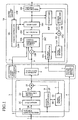
- Fig. 1 is a block diagram showing a configuration of a video transcoder (video data converter) of an embodiment 1 in accordance with the present invention.
- an MPEG-2 decoder 2 receives input compression data 1 compressed according to a coding scheme conforming to MPEG-2, and generates a decoded picture 5 from the input compression data 1.
- a variable length decoder 2A carries out syntax analysis of the input compression data 1 according to the MPEG-2 standard, and generates prediction residual signal coded data 2B, coding mode information 3 and motion vector information 4.
- a dequantizer 2C dequantizes the prediction residual signal coded data 2B generated by the variable length decoder 2A.
- An inverse DCT section 2D carries out the inverse DCT of the prediction residual signal coded data after the dequantization, and outputs prediction residual signal decoded values 2E.
- a motion compensator 2F generates a predictive picture 2I according to the motion vector information 4 generated by the variable length decoder 2A and reference picture data 2H stored in a frame memory 2G.
- An adder 2J adds the prediction residual signal decoded values 2E output from the inverse DCT section 2D and the predictive picture 2I generated by the motion compensator 2F, and generates a decoded picture 5.
- the frame memory 2G stores the decoded picture 5 as the reference picture data 2H.
- a resolution converter 6 converts the resolution of the decoded picture 5 generated by the MPEG-2 decoder 2 by downscaling pixel areas by two in the vertical and horizontal directions.
- the motion vector mapping section 7 generates motion vector mapping information 11 (a candidate of the motion vector) that can be used by the MPEG-4 coding from the motion vector information 4 generated by the variable length decoder 2A.
- the coding mode estimator 8 decides coding mode setting information 12 to be used by the MPEG-4 coding from the coding mode information 3 generated by the variable length decoder 2A.
- an MPEG-4 encoder 10 encodes the decoded picture 9 whose resolution is converted by the resolution converter 6.
- a motion compensator 10A generates a predictive picture 10C in accordance with the motion vector mapping information 11 and reference picture data stored in a frame memory 10M.
- a subtracter 10P generates a prediction residual signal by calculating a difference between the input signal 9 (that is, the decoded picture whose resolution is converted by the resolution converter 6) and the predictive picture 10C generated by the motion compensator 10A.
- a coding parameter deciding section 10B decides the coding mode and motion vector used for the coding on a macroblock by macroblock basis of the MPEG-4 according to the coding mode setting information 12 and the like.
- a DCT section 10D carries out the DCT of the prediction residual signal generated by the subtracter 10P when the coding mode decided by the coding parameter deciding section 10B is either an INTER mode or an INTER4V mode, and performs the DCT of the input signal 9 when the coding mode is an INTRA mode.
- a quantizer 10E quantizes the output signal of the DCT section 10D.
- a dequantizer 10F dequantizes the output signal of the quantizer 10E.
- An inverse DCT section 10G carries out the inverse DCT of the output signal of the dequantizer 10F, and outputs prediction residual signal decoded values 10H.
- An adder 10Q adds the prediction residual signal decoded values 10H output from the inverse DCT section 10G and the predictive picture 10C generated by the motion compensator 10A.
- the addition result 10I is stored in a frame memory 10M to be used for the MC of a subsequent frame.
- a variable length coder 10J arranges the output signal of the quantizer 10E in a format of the MPEG-4 video stream.
- a coding controller 10L controls the coding parameter deciding section 10B, quantizer 10E, dequantizer 10F and the like.
- the input compression data 1 compressed according to the MPEG-2 compliant coding scheme is input to the MPEG-2 decoder 2.
- variable length decoder 2A of the MPEG-2 decoder 2 carries out the syntax analysis of the input compression data 1 according to the MPEG-2 standard, and generates the prediction residual signal coded data 2B, coding mode information 3 and motion vector information 4.
- the dequantizer 2C receiving the prediction residual signal coded data 2B from the variable length decoder 2A, dequantizes the prediction residual signal coded data 2B.
- the inverse DCT section 2D carries out the inverse DCT of the prediction residual signal coded data, and outputs the prediction residual signal decoded values 2E.
- the motion compensator 2F receives the motion vector information 4 from the variable length decoder 2A, and generates the predictive picture 2I in accordance with the motion vector information 4 and the reference picture data 2H stored in the frame memory 2G.
- the motion vector information 4 is assumed to include all the information on the MC such as a flag indicating whether the frame prediction or field prediction is to be done, besides motion vector values.
- the adder 2J When the motion compensator 2F generates the predictive picture 2I, the adder 2J generates the decoded picture 5 by adding the predictive picture 2I and the prediction residual signal decoded values 2E output from the inverse DCT section 2D.
- the decoded picture 5 is stored in the frame memory 2G as the reference picture data 2H to be used for the subsequent frame motion compensation.
- the MPEG-2 decoded picture 5 generated by the MPEG-2 decoder 2 is input to the resolution converter 6 serving as a spatial resolution converter.
- the resolution converter 6 carries out pixel decimation based on a specified downsampling filter to reduce the resolution of the MPEG-2 decoded picture 5 to half the spatial resolution in the vertical and horizontal directions, for example.
- the result is the input signal 9 to the MPEG-4 encoder 10.
- decimation of all the B frames can reduce the frame rate to 1/3.
- MPEG-2 I (Intra) frames remain as MPEG-4 I (Intra) frames
- MPEG-2 P (Unidirectionally Predictive) frames remain as MPEG-4 P (Unidirectionally Predictive) frames after the conversion.
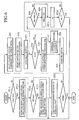
- Fig. 2 is a flowchart illustrating a procedure of the motion vector mapping and coding mode decision by the video transcoder.
- the MPEG-2 decoded picture 5 and the input signal 9 to the MPEG-4 encoder 10 have half the spatial resolution in the vertical and horizontal directions. Accordingly, the following procedure is assumed to be carried out on a 2 ⁇ 2 macroblock basis of MPEG-2, that is, on a single macroblock basis of MPEG-4.
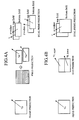
- Figs. 3A and 3B are diagrams each illustrating a unit of transcoding involving the resolution conversion.
- MPEG-4 one or four motion vectors are assigned to a macroblock, thereby providing two motion vector mapping methods as shown in Figs. 3A and 3B: In Fig. 3A, four MPEG-2 motion vectors are converted to one MPEG-4 motion vector; and in Fig. 3B, four MPEG-2 motion vectors are converted to four MPEG-4 motion vectors.
- the coding mode estimator 8 checks on the coding mode distribution in 2 ⁇ 2 macroblocks of MPEG-2 as shown in Figs. 3A and 3B.
- the coding mode after the conversion to be used by the MPEG-4 coding are forcedly put into INTRA or SKIP. In this case, all the motion vectors are placed at zero, and all the following steps are skipped.
- the INTRA mode is a mode of coding within each frame without using the motion prediction
- the SKIP mode is a mode of copying the picture data at the same position in the reference picture without transmitting the coding information.
- the coding mode setting information 12 output from the coding mode estimator 8 includes three possible choices of forced INTRA mode, forced SKIP mode, and possible INTER mode.
- the motion vector candidates used by the MPEG-4 encoder 10 are determined from the MPEG-2 motion vectors in the 2 ⁇ 2 macroblocks output from the variable length decoder 2A of the MPEG-2 decoder 2.
- the process is carried out by the motion vector mapping section 7.
- MPEG-2 which supports compression coding of an interlace signal, can select one of two coding modes: frame structure coding using a frame as a unit of coding; and field structure coding using a field as a unit of coding.
- a macroblock consisting of 16 ⁇ 16 pixels is composed of a frame picture segment, and in the field structure coding, the macroblock is composed of a field picture segment.
- the frame is defined as picture data consisting of a top field (field composed of upper lines) and a bottom field (field composed of lower lines) combined in comb fashion. Accordingly, a macroblock in the field structure coding covers twice the area in the vertical direction compared with a macroblock in the frame picture segment.
- Figs. 4A and 4B are diagrams each illustrating a type of a motion prediction mode in the MPEG-2 video coding.
- Fig. 4A illustrates a motion prediction mode usable for the frame structure coding
- Fig. 4B illustrates a motion prediction mode usable for the field structure coding
- the frame prediction predicts a macroblock consisting of a frame picture by a single motion vector v fr
- the field prediction makes a prediction for individual field segments of the macroblock consisting of the frame picture by separate motion vectors v tf and v bf .
- the top field prediction refers to the top field
- the bottom field prediction refers to the bottom field
- the top field prediction refers to the top field
- the bottom field prediction refers to the bottom field
- the top field prediction refers to the top field
- the bottom field prediction refers to the bottom field
- the top field prediction refers to the top field
- the bottom field prediction refers to the bottom field
- the second predictive picture with a motion vector obtained by adding a small differential motion vector dmv to a result obtained by scaling the vector v based on the inter-field distance. Then it uses the arithmetic mean of the first and second predictive pictures as the predictive picture of each field.
- the field prediction predicts a macroblock composed of a field picture with a single motion vector v fi .
- the 16x8 prediction is made by dividing the macroblock composed of the field picture into two segments of upper and lower 16x8 segments, and by making prediction with individual motion vectors v fi,upper and v fi,lower .
- the prediction is made by applying the same rule as in the frame structure coding to the field.
- the motion vector mapping section 7 In response to the MPEG-2 motion prediction mode, the motion vector mapping section 7 generates the motion vectors for the MPEG-4 coding.
- the present embodiment 1 selects the motion vectors used for the MPEG-4 coding in the following procedure.
- the motion vector defined for each MPEG-2 macroblock is downscaled to the motion vector after the resolution conversion in accordance with the characteristics of the prediction. Then, the four motion vectors corresponding to the 2 ⁇ 2 macroblocks of MPEG-2 are determined uniquely, and are made motion vector candidates for the MPEG-4 INTER4V mode.
- the INTER4V mode refers to a mode corresponding to the case of Fig. 3B, which divides the 16 ⁇ 16 pixel macroblock defined in the frame picture segment into four 8 ⁇ 8 pixel blocks, and makes the prediction with the individual motion vectors of the blocks.
- the present step ST1 selects the motion vector candidates for the INTER4V mode according to the following rules.
- a motion vector candidate is generated by halving the motion vector v fr in the horizontal direction and vertical direction.
- a motion vector candidate is generated by halving the motion vector v tf of the top field in the horizontal direction.
- a motion vector candidate is generated by halving the average value of the motion vector v for the top field and ⁇ v + dmv in the horizontal direction.
- a motion vector candidate is generated by halving the motion vector v fi in the horizontal direction and by quartering it in the vertical direction.
- a motion vector candidate is generated by averaging the motion vectors v fi,upper and v fi,lower , and then by halving the average in the horizontal direction and vertical direction.
- a motion vector candidate is generated by halving the average of the motion vector v and ⁇ v + dmv in the horizontal direction and by quartering it in the vertical direction.
- the INTER mode refers to a mode corresponding to the case of Fig. 3A, which predicts a macroblock composed of 16 ⁇ 16 pixels defined in the frame picture segment with a single motion vector.
- the motion vector candidates for the INTER and INTER4V modes which are selected in the foregoing sections 2-1) and 2-2), are supplied to the MPEG-4 encoder 10 as the motion vector mapping information 11.
- the motion vector candidates to be used by the MPEG-4 INTER and INTER4V modes are selected. Then, from among these modes and the remaining possible coding modes, INTRA mode and SKIP mode, the mode with the highest coding efficiency is selected. As a result, the final coding mode and motion vectors are decided. The processing is carried out by the coding parameter deciding section 10B.
- the mode decision uses the rate-distortion cost J m given by the following equation as a decision reference.
- m is a coding mode type
- v m is a motion vector in the mode m
- ⁇ m is a constant determined in accordance with the mode m
- E m is a prediction error estimation value in the mode m
- R vm is a motion vector rate when the motion vector is v m
- ⁇ is a positive constant
- m* and v m * are the coding mode and motion vectors selected as a result of the present estimation.
- the coding mode decision of the present section 3 can be made on the basis of either the prediction error estimation value or the motion vector rate.
- the prediction error estimation value E m associated with the SKIP, INTER or INTER4V mode can be defined, for example, as the sum of absolute values of the differences between the input signal 9 and the predictive picture candidates obtained from the motion compensator 10A using the motion vectors v m . It is assumed here that the motion vectors v m are zero and R vm are also zero in the case of SKIP. To evaluate the INTRA mode by the same estimation equation, the E m of the INTRA mode obtained as follows can be used.
- the average values of the luminance signal in the input signal 9 within the macroblocks are considered as the predictive picture candidates; second, the differences are obtained by subtracting the predictive picture candidates from the input signal 9; and third, the sum of the absolute values of differences is used as the E m of the INTRA mode.
- the E m can also be defined by considering not only the luminance signal, but also the color-difference components (Cb and Cr components).
- the estimation weighting for the E m can be carried out by adding offset values O m rather than by multiplying the weights ⁇ m .
- ⁇ the following value can be used which is disclosed in Gary J. Sullivan and Thomas Wiegand, "Rate-Distortion Optimization for Video Compression", IEEE Signal Processing Magazine, vol. 15, no. 6, pp. 74-90, Nov., 1998.
- ⁇ 0.85* Q P 2 where Qp is a quantization step parameter of the target macroblocks to be coded.
- m is defined as a counter for convenience' sake, and the foregoing process is described in the form of a loop processing of m. If a decision is made that the INTER mode is worth estimation from the coding mode setting information 12 output from the coding mode estimator 8, the processing is started after initializing the m and cost estimate min_J (step ST3).
- the conventional technology discloses the selection of the motion vector candidates as described in the foregoing section 1), it does not estimate the rate cost of the resultant motion vector itself, nor its impact on the MPEG-4 coding.
- the motion vector rate cannot be neglected in the low rate MPEG-4 coding, using the foregoing decision norm makes it possible to select the candidate that will provide optimum tradeoff between the rate and prediction accuracy from the INTER and INTER4V motion vector candidates.
- deciding the INTRA or SKIP by a similar estimation measure makes it possible to decide the motion vectors and coding mode to be used for the MPEG-4 coding at once using the same decision norm.
- the motion vector mapping information 11 and coding mode setting information 12 which are supplied to the MPEG-4 encoder 10 in such a manner as to reuse the motion vector information and coding mode information extracted from the input compression data 1, are used for coding the input signal 9, which is the MPEG-2 decoded picture after the resolution conversion.
- These two items of information are utilized by the coding parameter deciding section 10B to decide the coding mode and motion vectors that are used for coding on a macroblock by macroblock basis of MPEG-4.
- the motion compensator 10A generates the predictive picture 10C, followed by generating the prediction residual signal by computing the differences between the predictive picture 10C and the input signal.
- the prediction residual signal passes through the DCT section 10D and quantizer 10E to be arranged in the MPEG-4 video stream by the variable length coder 10J.
- the input signal 9 itself passes through the DCT and quantization to undergo the variable length coding.
- the flag (not_coded) indicating that the macroblock is to be skipped is multiplexed to the bit stream to undergo the coding.
- the prediction residual signal after the quantization passes through the dequantizer 10F and inverse DCT section 10G to be restored to the prediction residual signal decoded values 10H which are added to the predictive picture 10C.
- the addition results are stored in the frame memory 10M to be used for the MC for the subsequent frame.
- variable length coder 10J carries out within itself the prediction of the AC and DC components, and the scanning for the run-length coding of the DCT coefficients.
- the coding controller 10L carries out the coding control in accordance with the buffer occupied amount 10K. Specifically, the coding controller 10L decides a quantization step parameter (Qp) 10N on a video packet or macroblock basis.
- the video packet is a unit constructed by grouping a plurality of macroblocks in the raster scanning sequence, and is used for early recovering from an error by cutting off a dependent relationship with the surrounding image segments within the frame.
- the quantization step parameter 10N thus decided is supplied to the quantizer 10E and dequantizer 10F, as well as to the coding parameter deciding section 10B to compute the value ⁇ .
- the transcoder which carries out the conversion from the MPEG-2 video data to the MPEG-4 video data, decides the optimum coding mode and motion vectors for the MPEG-4 coding with reusing the motion vectors and the coding mode information in the MPEG-2 data.
- the transcoder can improve the quality of the transcode video with a small amount of computation.
- the present embodiment 1 simplifies the motion vector detection with a large computational load. Accordingly, it can improve the video transcoding quality from MPEG-2 to MPEG-4 as compared with the conventional simple motion vector reusing method.
- the present configuration can further improve the coding efficiency by closely combining either the decision process of the quantization step parameter (Qp) 10N by the coding controller 10L or the setting unit such as a frame, video packet and macroblock, with the motion vector-coding mode information reuse scheme of MPEG-2 as described in the foregoing section 3 ⁇ .
- the transcoder with the present configuration is applicable to all the MPEG-4 simple profile compliant multi-mode coding schemes such as an MPEG-4 advanced simple profile and a case supporting the motion prediction option described in Annex F in ITU-T H.263.
- the resolution converter 6 operates not only as the spatial resolution converter, but also as a temporal resolution converter for carrying out the temporal resolution (frame rate) conversion by decimating the P frames to which the effect of the motion prediction is transmitted.
- the resolution converter 6 can function as both the spatial resolution converter and temporal resolution converter, or as the temporal resolution converter without functioning as the spatial resolution converter.
- Fig. 5 is a block diagram showing a configuration of a video transcoder (video data converter) of the embodiment 2 in accordance with the present invention.
- the configuration of the transcoder of the present embodiment 2 has the same internal configuration as the transcoder of the embodiment 1 as shown in Fig. 1. It differs from the foregoing embodiment 1 in the operation of the resolution converter 6 and motion vector mapping section 7, which will be described in detail here.
- the decoding is the same as that of the foregoing embodiment 1.
- the MPEG-2 decoded picture 5 is halved in the spatial resolution in the vertical and horizontal directions by the pixel decimation based on a specified downsampling filter in the resolution converter 6.
- the input frame rate of the input signal 9 to the MPEG-4 encoder 10 is controlled.
- the present embodiment 2 is configured such that it carries out not only the decimation of the B frames as described in the foregoing embodiment 1, but also the decimation of the P frames according to the instruction of the coding frame instruction information 13.
- the coding frame instruction information 13 indicates the coding frame rate when the MPEG-4 encoder 10 carries out the coding at a fixed frame rate. In contrast, when the MPEG-4 encoder 10 carries out the coding at a variable frame rate, the coding frame instruction information 13 indicates information on the display timing of the target frame to be coded, or information on a frame number offset from the immediately previous MPEG-4 coding frame.
- the process is carried out by the motion vector mapping section 7, coding mode estimator 8, and coding parameter deciding section 10B in the MPEG-4 encoder 10 as shown in Fig. 5.
- Fig. 6 is a flowchart illustrating a procedure of the motion vector mapping and coding mode decision by the video transcoder.
- the coding mode estimator 8 checks on the coding mode distribution in 2 ⁇ 2 macroblocks of MPEG-2 as shown in Figs. 3A and 3B.
- Fig. 7 is a diagram illustrating the monitoring operation in the MPEG-2 coding mode of the coding mode estimator 8.
- the present embodiment 2 monitors the MPEG-2 coding mode during the frame decimation from the immediately previous target frame of the MPEG-4 coding to the current target frame of the MPEG-4 coding (steps ST12 and ST13). If at least one occasion takes place when all the four macroblocks of MPEG-2 are INTRA mode, the coding mode after the conversion to be used by the MPEG-4 coding is forcedly made INTRA mode.
- the coding mode to be used by the MPEG-4 coding is forcedly made SKIP if the SKIP continues during the frame decimation from the immediately previous target frame of the MPEG-4 coding to the current target frame of the MPEG-4 coding. In contrast, if an occasion other than the SKIP takes place even once, the possibility of the INTER mode is checked.
- the monitoring of the MPEG-2 coding mode during the frame decimation is carried out for the P frames only, so that I frames undergo the MPEG-4 coding without being subjected to the decimation. Thus, the monitoring of the MPEG-2 coding mode is reset (steps ST14 and ST15).
- the coding mode setting information 12 output from the coding mode estimating section 8 includes three possible choices of forced INTRA mode, forced SKIP mode, and INTER mode (step ST0).
- the MPEG-2 motion vectors are monitored during the frame decimation from the immediately previous target frame of the MPEG-4 coding to the current target frame of the MPEG-4 coding according to the coding frame instruction information 13 as shown in Fig. 8 (steps ST12 and ST13). Then, the motion vector candidates used by the MPEG-4 encoder 10 are decided from the MPEG-2 motion vectors obtained as a result of the monitoring.
- the process is carried out by the motion vector mapping section 7. According to the results of the foregoing section 1), in the present process, a case is considered in which the SKIP mode or INTER mode occurs during the frame decimation as the MPEG-2 coding mode as a rule. Thus, the following rule is applied.
- the motion vector candidates to be used in the MPEG-4 INTER and INTER4V modes have been selected. Then, from among these modes and the remaining possible coding modes, INTRA mode and SKIP mode, the mode with the highest coding efficiency is selected (steps ST3-ST11). As a result, the final coding mode and motion vectors are decided.
- the processing is carried out by the coding parameter deciding section 10B.
- the processing by the coding parameter deciding section 10B from now on is in conformity with the section 3) of the foregoing embodiment 1. In this case, however, the reference picture the motion prediction uses is a local decoded picture of the MPEG-4 coded frame immediately previous to the current target frame to be coded.
- the present embodiment 2 can select the optimum mode and the motion vectors associated with it from among all the possible coding modes in the MPEG-4 coding even in the transcoding that carries out temporal resolution (frame rate conversion) involving the P frame decimation.
- the present embodiment 2 simplifies the motion vector detection with a large computational load even in the transcoder that carries out the P frame decimation. Accordingly, it can improve the quality of the video transcoding from MPEG-2 to MPEG-4 as compared with the conventional simple motion vector reusing method.
- the transcoder with the present configuration is also applicable to all the MPEG-4 simple profile compliant multi-mode coding schemes such as the MPEG-4 advanced simple profile and a case supporting the motion prediction option described in Annex F of ITU-T H.263.
- the present invention is applicable to transcoding in general targeted for MC + DCT video coding schemes.
- the video data converter and video data converting method in accordance with the present invention are applicable to those requiring improvement in transcode video quality by a small amount of computation, when carrying out a variety of conversions of video compression data in conformity with various video compression-decompression schemes based on international standards.
Landscapes
- Engineering & Computer Science (AREA)
- Multimedia (AREA)
- Signal Processing (AREA)
- Compression Or Coding Systems Of Tv Signals (AREA)
- Compression, Expansion, Code Conversion, And Decoders (AREA)
- Color Television Systems (AREA)
- Television Systems (AREA)
Abstract
In an MPEG-2 decoder (2), a variable length decoder (2A)
carries out syntax analysis of input compression data (1)
according to the MPEG-2 standard, and generates coding mode
information (3), motion vector information (4) and prediction
residual signal (2B). The prediction residual signal (2B) is
transformed to a decoded picture (5) through a dequantizer (2C)
and the like, and is supplied to an MPEG-4 encoder (10) via a
resolution converter (6). In the MPEG-4 encoder (10), a coding
parameter deciding section (10B) decides a motion vector
according to a prediction error estimation value for evaluating
a prediction efficiency when using a motion vector-candidate
generated by a motion vector mapping section (7), and according
to a value for evaluating a motion vector rate when using the
motion vector candidate.
Description
The present invention relates to a video data converter
and video data converting method for carrying out various
conversions of video compression data conforming to video
compression-decompression schemes of a variety of international
standards.
At present, international standard video coding schemes
such as MPEG and ITU-T H.26x are utilized in a variety of
applications in the fields of broadcasting, communications and
packages such as digital broadcasting (satellite, terrestrial,
cable), DVDs, video CDs, the Internet and mobile communications.
The need is growing for reusing video contents compressed
by these coding schemes in a variety of platforms under
conditions different in supporting coding schemes, transmission
bit rates, spatial resolutions (frame sizes), temporal
resolutions (frame rates). With this as a background, intensive
research and development of video transcoding technology has
been conducted.
In particular, the standard video coding schemes such as
MPEG and ITU-T H.26x share the syntax of the coded data to some
extent because they are consistently based on the signal
redundancy reduction in the time-axis direction according to
motion compensation (called MC from now on) and the signal
redundancy reduction in the spatial direction according to
discrete cosine transform (called DCT from now on). Considering
conversions using them at a bit stream level, the transcoding
technology that reduces computational load has been studied as
to the standard video coding schemes.
Above all, converting MPEG-2 videos with an NTSC resolution
(704 × 480 pixels per frame and 30 frames/sec) to lower frame
rate MPEG-4 or H.263 videos with an SIF (352 × 240 pixels) becomes
a hot topic because of an increasing demand for making effective
use of existing MPEG-2 contents (refer to Wang Xing Guo, Zheng
Wei Guo, and Ishfaq Ahmad, "MPEG-2 To MPEG-4 Transcoding",
Workshop and Exhibition on MPEG-4 (WEMP) 2001, for example).
In such video transcoding technology, it is important to
convert motion vectors in an MPEG-2 video stream input to a
transcoder into motion vectors usable in the MPEG-4 coding.
Since divide-by-two resolution conversion is made in both
the vertical and horizontal directions, four macroblocks in an
input MPEG-2 stream exactly correspond to one macroblock of the
MPEG-4 coding. The problem is a one that estimates a motion
vector after the resolution conversion from four original motion
vectors at the maximum, and a variety of studies and reports
have been made about it up to now. For example, B. Shen et al.,
"Adaptive Motion-Vector Resampling for Compressed Video
Downsampling", IEEE Transactions on Circuits And Systems for
Video Technology, vol. 9, no. 6, Sep. 1999 discloses a technique
of calculating the weighted average of the four motion vectors
by assigning larger weights to motion vectors with a larger
prediction residue in the input compression data.
It is so to speak a method of deciding the values of the
motion vectors to be converted by using the prediction residual
signal in the input compression data as a reference and in
accordance with its activity values. A variation of this method
is reported by M. R. Hashemi, et al., "Compressed Domain Motion
Vector Resampling for Downscaling of MPEG Video", IEEE
International Conference on Image Processing, Kobe, Japan, Oct.
1999.
With the foregoing configuration, the conventional video
data converting method has problems in that its application is
limited to a case where the motion vector to be converted is
only one, and that it does not ensure the optimum conditions
in terms of coding performance of the motion vector after the
conversion.
The present invention is implemented to solve the foregoing
problems. Therefore it is an object of the present invention
to provide a video data converter and video data converting
method capable of converting motion vectors considering the
impact of the coding performance within a second video coding
scheme.
According to an aspect of the present invention, there is
provided a video data converter for converting input video coded
data based on a first video coding scheme to video coded data
based on a second video coding scheme, the first video coding
scheme carrying out coding by dividing each frame of a video
signal into specified segments and by selecting coding
parameters including a motion vector for each specified segment,
and the second video coding scheme carrying out coding by
dividing each frame of the video signal into specified segments
and by selecting coding parameters for each specified segment,
the video data converter comprising: a motion vector mapping
section for generating a motion vector candidate to be used for
each specified segment of the second video coding scheme from
the motion vector in the coding parameters of each specified
segment of the first video coding scheme; and a coding parameter
deciding section for deciding a motion vector to be used in the
second video coding scheme from among the generated motion vector
candidates in the second video coding scheme according to a
prediction error estimation value that estimates a prediction
efficiency when using the motion vector candidates and according
to a value that estimates a motion vector rate when using the
motion vector candidates.
Thus, it offers an advantage of being able to covert the
motion vectors and the like considering impact of coding
performance in the second video coding scheme.
The best mode for carrying out the invention will now be
described with reference to the accompanying drawings to explain
the present invention in more detail.
The present embodiment 1 will be described by way of example
of a video transcoder that inputs MPEG-2 video data and outputs
MPEG-4 video data whose spatial resolution is downsampled-by-two
in the vertical and horizontal directions. The following
description is made under the assumption that the MPEG-4 is a
coding scheme conforming to the MPEG-4 simple profile.
Fig. 1 is a block diagram showing a configuration of a video
transcoder (video data converter) of an embodiment 1 in
accordance with the present invention. In Fig. 1, an MPEG-2
decoder 2 receives input compression data 1 compressed according
to a coding scheme conforming to MPEG-2, and generates a decoded
picture 5 from the input compression data 1. A variable length
decoder 2A carries out syntax analysis of the input compression
data 1 according to the MPEG-2 standard, and generates prediction
residual signal coded data 2B, coding mode information 3 and
motion vector information 4. A dequantizer 2C dequantizes the
prediction residual signal coded data 2B generated by the
variable length decoder 2A. An inverse DCT section 2D carries
out the inverse DCT of the prediction residual signal coded data
after the dequantization, and outputs prediction residual signal
decoded values 2E.
A motion compensator 2F generates a predictive picture 2I
according to the motion vector information 4 generated by the
variable length decoder 2A and reference picture data 2H stored
in a frame memory 2G. An adder 2J adds the prediction residual
signal decoded values 2E output from the inverse DCT section
2D and the predictive picture 2I generated by the motion
compensator 2F, and generates a decoded picture 5. The frame
memory 2G stores the decoded picture 5 as the reference picture
data 2H.
A resolution converter 6 converts the resolution of the
decoded picture 5 generated by the MPEG-2 decoder 2 by
downscaling pixel areas by two in the vertical and horizontal
directions. The motion vector mapping section 7 generates
motion vector mapping information 11 (a candidate of the motion
vector) that can be used by the MPEG-4 coding from the motion
vector information 4 generated by the variable length decoder
2A. The coding mode estimator 8 decides coding mode setting
information 12 to be used by the MPEG-4 coding from the coding
mode information 3 generated by the variable length decoder 2A.
According to MPEG-4, an MPEG-4 encoder 10 encodes the
decoded picture 9 whose resolution is converted by the resolution
converter 6. A motion compensator 10A generates a predictive
picture 10C in accordance with the motion vector mapping
information 11 and reference picture data stored in a frame
memory 10M. A subtracter 10P generates a prediction residual
signal by calculating a difference between the input signal 9
(that is, the decoded picture whose resolution is converted by
the resolution converter 6) and the predictive picture 10C
generated by the motion compensator 10A. A coding parameter
deciding section 10B decides the coding mode and motion vector
used for the coding on a macroblock by macroblock basis of the
MPEG-4 according to the coding mode setting information 12 and
the like.
A DCT section 10D carries out the DCT of the prediction
residual signal generated by the subtracter 10P when the coding
mode decided by the coding parameter deciding section 10B is
either an INTER mode or an INTER4V mode, and performs the DCT
of the input signal 9 when the coding mode is an INTRA mode.
A quantizer 10E quantizes the output signal of the DCT section
10D. A dequantizer 10F dequantizes the output signal of the
quantizer 10E. An inverse DCT section 10G carries out the
inverse DCT of the output signal of the dequantizer 10F, and
outputs prediction residual signal decoded values 10H. An adder
10Q adds the prediction residual signal decoded values 10H output
from the inverse DCT section 10G and the predictive picture 10C
generated by the motion compensator 10A. The addition result
10I is stored in a frame memory 10M to be used for the MC of
a subsequent frame.
A variable length coder 10J arranges the output signal of
the quantizer 10E in a format of the MPEG-4 video stream. A coding
controller 10L controls the coding parameter deciding section
10B, quantizer 10E, dequantizer 10F and the like.
Next, the operation will be described.
First, the input compression data 1 compressed according
to the MPEG-2 compliant coding scheme is input to the MPEG-2
decoder 2.
The variable length decoder 2A of the MPEG-2 decoder 2
carries out the syntax analysis of the input compression data
1 according to the MPEG-2 standard, and generates the prediction
residual signal coded data 2B, coding mode information 3 and
motion vector information 4.
The dequantizer 2C, receiving the prediction residual
signal coded data 2B from the variable length decoder 2A,
dequantizes the prediction residual signal coded data 2B.
Receiving the prediction residual signal coded data after
the dequantization from the dequantizer 2C, the inverse DCT
section 2D carries out the inverse DCT of the prediction residual
signal coded data, and outputs the prediction residual signal
decoded values 2E.
The motion compensator 2F receives the motion vector
information 4 from the variable length decoder 2A, and generates
the predictive picture 2I in accordance with the motion vector
information 4 and the reference picture data 2H stored in the
frame memory 2G. Here, the motion vector information 4 is
assumed to include all the information on the MC such as a flag
indicating whether the frame prediction or field prediction is
to be done, besides motion vector values.
When the motion compensator 2F generates the predictive
picture 2I, the adder 2J generates the decoded picture 5 by adding
the predictive picture 2I and the prediction residual signal
decoded values 2E output from the inverse DCT section 2D. Here,
the decoded picture 5 is stored in the frame memory 2G as the
reference picture data 2H to be used for the subsequent frame
motion compensation.
The MPEG-2 decoded picture 5 generated by the MPEG-2 decoder
2 is input to the resolution converter 6 serving as a spatial
resolution converter.
The resolution converter 6 carries out pixel decimation
based on a specified downsampling filter to reduce the resolution
of the MPEG-2 decoded picture 5 to half the spatial resolution
in the vertical and horizontal directions, for example. The
result is the input signal 9 to the MPEG-4 encoder 10.
As for the resolution conversion in the time-axis direction,
S. J. Wee, et al., ''Field-to-frame Transcoding with Spatial And
Temporal Downsampling", IEEE International Conference on Image
Processing, Kobe, Japan, Oct. 1999, for example, discloses a
relevant technique. It allows, when the MPEG-2 stream includes
B frames (Bidirectionally predictive frames), only a processing
of reducing the frame rate by decimating the B frames. This is
because unlike I (Intra) or P (Unidirectionally Predictive)
frames, the B frames themselves are not used to predict other
frames, and hence the decimation of the B frames does not affect
the quality of the other frames.
For example, as for a widely used coding pattern that
inserts two B frames between I (Intra) or P (Unidirectionally
Predictive) frames, decimation of all the B frames can reduce
the frame rate to 1/3. In the present embodiment 1, it is assumed
that MPEG-2 I (Intra) frames remain as MPEG-4 I (Intra) frames,
and that MPEG-2 P (Unidirectionally Predictive) frames remain
as MPEG-4 P (Unidirectionally Predictive) frames after the
conversion.
Now, the motion vector mapping and coding mode selection,
the subject matter of the present invention, will be described.
The process is carried out by the motion vector mapping section
7, the coding mode estimator 8, and the coding parameter deciding
section 10B of the MPEG-4 encoder 10 in Fig. 1.
Fig. 2 is a flowchart illustrating a procedure of the motion
vector mapping and coding mode decision by the video transcoder.
The MPEG-2 decoded picture 5 and the input signal 9 to the
MPEG-4 encoder 10 have half the spatial resolution in the
vertical and horizontal directions. Accordingly, the following
procedure is assumed to be carried out on a 2×2 macroblock basis
of MPEG-2, that is, on a single macroblock basis of MPEG-4. Figs.
3A and 3B are diagrams each illustrating a unit of transcoding
involving the resolution conversion.
In MPEG-4, one or four motion vectors are assigned to a
macroblock, thereby providing two motion vector mapping methods
as shown in Figs. 3A and 3B: In Fig. 3A, four MPEG-2 motion vectors
are converted to one MPEG-4 motion vector; and in Fig. 3B, four
MPEG-2 motion vectors are converted to four MPEG-4 motion
vectors.
First, the coding mode estimator 8 checks on the coding
mode distribution in 2 × 2 macroblocks of MPEG-2 as shown in Figs.
3A and 3B. When all the four macroblocks are in the INTRA mode
or in the SKIP mode, the coding mode after the conversion to
be used by the MPEG-4 coding are forcedly put into INTRA or SKIP.
In this case, all the motion vectors are placed at zero, and
all the following steps are skipped.
Here, the INTRA mode is a mode of coding within each frame
without using the motion prediction, and the SKIP mode is a mode
of copying the picture data at the same position in the reference
picture without transmitting the coding information.
Consequently, employing the INTER mode that carries out
the motion prediction by using the motion vectors, only when
at least one of the four macroblocks has the motion prediction
mode, can increase the coding efficiency. In this case, however,
the optimum mode in terms of the coding efficiency must be
redecided among the possible MPEG-4 coding modes according to
the following procedure 2) and onward.
Thus, the coding mode setting information 12 output from
the coding mode estimator 8 includes three possible choices of
forced INTRA mode, forced SKIP mode, and possible INTER mode.
When a decision is made at the foregoing section 1) that
the INTER mode is valuable, the motion vector candidates used
by the MPEG-4 encoder 10 are determined from the MPEG-2 motion
vectors in the 2×2 macroblocks output from the variable length
decoder 2A of the MPEG-2 decoder 2.
The process is carried out by the motion vector mapping
section 7.
MPEG-2, which supports compression coding of an interlace
signal, can select one of two coding modes: frame structure
coding using a frame as a unit of coding; and field structure
coding using a field as a unit of coding.
In the frame structure coding, a macroblock consisting of
16×16 pixels is composed of a frame picture segment, and in the
field structure coding, the macroblock is composed of a field
picture segment. The frame is defined as picture data consisting
of a top field (field composed of upper lines) and a bottom field
(field composed of lower lines) combined in comb fashion.
Accordingly, a macroblock in the field structure coding covers
twice the area in the vertical direction compared with a
macroblock in the frame picture segment.
Figs. 4A and 4B are diagrams each illustrating a type of
a motion prediction mode in the MPEG-2 video coding.
Fig. 4A illustrates a motion prediction mode usable for
the frame structure coding, and Fig. 4B illustrates a motion
prediction mode usable for the field structure coding. In Fig.
4A, the frame prediction predicts a macroblock consisting of
a frame picture by a single motion vector vfr. In contrast, the
field prediction makes a prediction for individual field
segments of the macroblock consisting of the frame picture by
separate motion vectors vtf and vbf.
In this case, it can select one of the top field and bottom
field as the field to be referred to. As for dual-prime
prediction, it generates a first predictive picture from the
same field position with a single field vector v (the top field
prediction refers to the top field, and the bottom field
prediction refers to the bottom field). In addition, from the
different field position, it generates a second predictive
picture with a motion vector obtained by adding a small
differential motion vector dmv to a result obtained by scaling
the vector v based on the inter-field distance. Then it uses
the arithmetic mean of the first and second predictive pictures
as the predictive picture of each field.
In Fig. 4B, the field prediction predicts a macroblock
composed of a field picture with a single motion vector vfi. The
16x8 prediction is made by dividing the macroblock composed of
the field picture into two segments of upper and lower 16x8
segments, and by making prediction with individual motion
vectors vfi,upper and vfi,lower. As for the dual-prime prediction, the
prediction is made by applying the same rule as in the frame
structure coding to the field.
In response to the MPEG-2 motion prediction mode, the motion
vector mapping section 7 generates the motion vectors for the
MPEG-4 coding. The present embodiment 1 selects the motion
vectors used for the MPEG-4 coding in the following procedure.
The motion vector defined for each MPEG-2 macroblock is
downscaled to the motion vector after the resolution conversion
in accordance with the characteristics of the prediction. Then,
the four motion vectors corresponding to the 2×2 macroblocks
of MPEG-2 are determined uniquely, and are made motion vector
candidates for the MPEG-4 INTER4V mode.
The INTER4V mode refers to a mode corresponding to the case
of Fig. 3B, which divides the 16×16 pixel macroblock defined
in the frame picture segment into four 8×8 pixel blocks, and
makes the prediction with the individual motion vectors of the
blocks. The present step ST1 selects the motion vector
candidates for the INTER4V mode according to the following rules.
A motion vector candidate is generated by halving the motion
vector vfr in the horizontal direction and vertical direction.
A motion vector candidate is generated by halving the motion
vector vtf of the top field in the horizontal direction.
A motion vector candidate is generated by halving the
average value of the motion vector v for the top field and αv
+ dmv in the horizontal direction.
Only the vector used for the prediction of the top field
is extracted in the following.
A motion vector candidate is generated by halving the motion
vector vfi in the horizontal direction and by quartering it in
the vertical direction.
A motion vector candidate is generated by averaging the
motion vectors vfi,upper and vfi,lower, and then by halving the average
in the horizontal direction and vertical direction.
A motion vector candidate is generated by halving the
average of the motion vector v and αv + dmv in the horizontal
direction and by quartering it in the vertical direction.
From the four motion vectors determined above, the motion
vector for the MPEG-4 INTER mode is decided. The INTER mode
refers to a mode corresponding to the case of Fig. 3A, which
predicts a macroblock composed of 16×16 pixels defined in the
frame picture segment with a single motion vector.
It can be decided by the method disclosed by B. Shen, et
al., "Adaptive Motion-Vector Resampling for Compressed Video
Downsampling", IEEE Transactions on Circuits And Systems for
Video Technology, vol. 9, no. 6, Sep. 1999.
The motion vector candidates for the INTER and INTER4V modes,
which are selected in the foregoing sections 2-1) and 2-2), are
supplied to the MPEG-4 encoder 10 as the motion vector mapping
information 11.
In the foregoing section 2), the motion vector candidates
to be used by the MPEG-4 INTER and INTER4V modes are selected.
Then, from among these modes and the remaining possible coding
modes, INTRA mode and SKIP mode, the mode with the highest coding
efficiency is selected. As a result, the final coding mode and
motion vectors are decided. The processing is carried out by
the coding parameter deciding section 10B.
The mode decision uses the rate-distortion cost Jm given
by the following equation as a decision reference.
 where m is a coding mode type, vm is a motion vector in the mode
m, M is a set of the mode types (M = (INTRA, SKIP, INTER, INTER4V) ) ,
αm is a constant determined in accordance with the mode m, Em
is a prediction error estimation value in the mode m, Rvm is a
motion vector rate when the motion vector is vm, λ is a positive
constant, and m* and vm* are the coding mode and motion vectors
selected as a result of the present estimation. Incidentally,
the coding mode decision of the present section 3) can be made
on the basis of either the prediction error estimation value
or the motion vector rate.
where m is a coding mode type, vm is a motion vector in the mode
m, M is a set of the mode types (M = (INTRA, SKIP, INTER, INTER4V) ) ,
αm is a constant determined in accordance with the mode m, Em
is a prediction error estimation value in the mode m, Rvm is a
motion vector rate when the motion vector is vm, λ is a positive
constant, and m* and vm* are the coding mode and motion vectors
selected as a result of the present estimation. Incidentally,
the coding mode decision of the present section 3) can be made
on the basis of either the prediction error estimation value
or the motion vector rate.
The prediction error estimation value Em associated with
the SKIP, INTER or INTER4V mode can be defined, for example,
as the sum of absolute values of the differences between the
input signal 9 and the predictive picture candidates obtained
from the motion compensator 10A using the motion vectors vm. It
is assumed here that the motion vectors vm are zero and Rvm are
also zero in the case of SKIP. To evaluate the INTRA mode by
the same estimation equation, the Em of the INTRA mode obtained
as follows can be used. First, the average values of the
luminance signal in the input signal 9 within the macroblocks
are considered as the predictive picture candidates; second,
the differences are obtained by subtracting the predictive
picture candidates from the input signal 9; and third, the sum
of the absolute values of differences is used as the Em of the
INTRA mode. Incidentally, the Em can also be defined by
considering not only the luminance signal, but also the
color-difference components (Cb and Cr components).
Widely used color component sampling ratios of the target
MPEG-2 and MPEG-4 video to be coded are Y:Cb:Cr = 4:2:0 (when
the Cb and Cr components in the 8×8 pixel area correspond to
the luminance component in the 16×16 pixel area). Accordingly,
as in the case of the luminance component of the foregoing INTRA
mode, it is possible to consider the average values (DC
components) of the 8×8 segment of the Cb and Cr components as
the predictive picture candidates, and to take into
consideration the sum of the absolute values of the differences
obtained by subtracting the average values from the Cb and Cr
components of the input signal 9. This makes it possible to
estimate the motion vectors considering not only the degree of
similarity between the luminance patterns, but also the degree
of similarity between colors, thereby being able to prevent the
degradation due to color deviation conspicuous to visual
perception.
In the INTRA mode, although the motion vector rate Rvm is
zero, the number of DCT coefficients to be coded are great. Thus,
estimation weights for the Em are varied in advance by the weights
αm. This makes it possible to make the mode decision by
simulatively considering the addition of the DCT coefficient
rate in the INTRA mode.
The estimation weighting for the Em can be carried out by
adding offset values Om rather than by multiplying the weights
αm.
As the value λ, the following value can be used which is
disclosed in Gary J. Sullivan and Thomas Wiegand, "Rate-Distortion
Optimization for Video Compression", IEEE Signal
Processing Magazine, vol. 15, no. 6, pp. 74-90, Nov., 1998.
λ= 0.85*QP 2
where Qp is a quantization step parameter of the target
macroblocks to be coded.
In Fig. 2, m is defined as a counter for convenience' sake,
and the foregoing process is described in the form of a loop
processing of m. If a decision is made that the INTER mode is
worth estimation from the coding mode setting information 12
output from the coding mode estimator 8, the processing is
started after initializing the m and cost estimate min_J (step
ST3).
After a decision is made as to whether m = 3 (INTRA) or
not (step ST4), the average value of the luminance value within
the macroblock is computed in the case of INTRA (step ST5).
Otherwise, the predictive picture candidate is generated by the
motion compensator 10B using the motion vectors vm determined
from the motion vector mapping information 11 (step ST6). As
for the results at step ST5 or step ST6, the sum is computed
of the absolute values of the differences between the results
and the luminance signal of the target macroblock to be coded
represented by the input signal 9, and the cost Jm is computed
by placing the sum as the Em (step ST7). At steps ST8 and ST9,
the candidate update is carried out to the mode m that will
minimize the cost. At step ST10, m is incremented, and the
processing is continued until the loop is completed at step ST11.
If a decision is made that the INTER mode is valuable at
step ST0 in the foregoing procedure, it is possible to select
the optimum mode and the motion vectors associated with the mode
from among all the possible coding modes in the MPEG-4 coding.
Although the conventional technology discloses the
selection of the motion vector candidates as described in the
foregoing section 1), it does not estimate the rate cost of the
resultant motion vector itself, nor its impact on the MPEG-4
coding. In particular, although the motion vector rate cannot
be neglected in the low rate MPEG-4 coding, using the foregoing
decision norm makes it possible to select the candidate that
will provide optimum tradeoff between the rate and prediction
accuracy from the INTER and INTER4V motion vector candidates.
In addition, deciding the INTRA or SKIP by a similar
estimation measure makes it possible to decide the motion vectors
and coding mode to be used for the MPEG-4 coding at once using
the same decision norm.
As a result of the foregoing processing, the motion vector
mapping information 11 and coding mode setting information 12,
which are supplied to the MPEG-4 encoder 10 in such a manner
as to reuse the motion vector information and coding mode
information extracted from the input compression data 1, are
used for coding the input signal 9, which is the MPEG-2 decoded
picture after the resolution conversion. These two items of
information are utilized by the coding parameter deciding
section 10B to decide the coding mode and motion vectors that
are used for coding on a macroblock by macroblock basis of MPEG-4.
As a result, in one of the INTER and INTER4V mode, the motion
compensator 10A generates the predictive picture 10C, followed
by generating the prediction residual signal by computing the
differences between the predictive picture 10C and the input
signal. The prediction residual signal passes through the DCT
section 10D and quantizer 10E to be arranged in the MPEG-4 video
stream by the variable length coder 10J.
In the INTRA mode, the input signal 9 itself passes through
the DCT and quantization to undergo the variable length coding.
In the SKIP mode, only the flag (not_coded) indicating that the
macroblock is to be skipped is multiplexed to the bit stream
to undergo the coding.
The prediction residual signal after the quantization
passes through the dequantizer 10F and inverse DCT section 10G
to be restored to the prediction residual signal decoded values
10H which are added to the predictive picture 10C. The addition
results are stored in the frame memory 10M to be used for the
MC for the subsequent frame.
Incidentally, the variable length coder 10J carries out
within itself the prediction of the AC and DC components, and
the scanning for the run-length coding of the DCT coefficients.
In addition, since the output of the variable length coder
10J is transmitted or recorded after being buffered, the coding
controller 10L carries out the coding control in accordance with
the buffer occupied amount 10K. Specifically, the coding
controller 10L decides a quantization step parameter (Qp) 10N
on a video packet or macroblock basis. The video packet is a
unit constructed by grouping a plurality of macroblocks in the
raster scanning sequence, and is used for early recovering from
an error by cutting off a dependent relationship with the
surrounding image segments within the frame. The quantization
step parameter 10N thus decided is supplied to the quantizer
10E and dequantizer 10F, as well as to the coding parameter
deciding section 10B to compute the value λ.
As described above, according to the present embodiment
1, the transcoder, which carries out the conversion from the
MPEG-2 video data to the MPEG-4 video data, decides the optimum
coding mode and motion vectors for the MPEG-4 coding with reusing
the motion vectors and the coding mode information in the MPEG-2
data. Thus, it can improve the quality of the transcode video
with a small amount of computation.
In particular, the present embodiment 1 simplifies the
motion vector detection with a large computational load.
Accordingly, it can improve the video transcoding quality from
MPEG-2 to MPEG-4 as compared with the conventional simple motion
vector reusing method.
Although not described in detail, the present configuration
can further improve the coding efficiency by closely combining
either the decision process of the quantization step parameter
(Qp) 10N by the coding controller 10L or the setting unit such
as a frame, video packet and macroblock, with the motion
vector-coding mode information reuse scheme of MPEG-2 as
described in the foregoing section 3 ○.
Although the foregoing description is made by way of example
of the MPEG-4 simple profile, the transcoder with the present
configuration is applicable to all the MPEG-4 simple profile
compliant multi-mode coding schemes such as an MPEG-4 advanced
simple profile and a case supporting the motion prediction option
described in Annex F in ITU-T H.263.
In the present embodiment 2, the resolution converter 6
operates not only as the spatial resolution converter, but also
as a temporal resolution converter for carrying out the temporal
resolution (frame rate) conversion by decimating the P frames
to which the effect of the motion prediction is transmitted.
The resolution converter 6 can function as both the spatial
resolution converter and temporal resolution converter, or as
the temporal resolution converter without functioning as the
spatial resolution converter.
Fig. 5 is a block diagram showing a configuration of a video
transcoder (video data converter) of the embodiment 2 in
accordance with the present invention. The configuration of the
transcoder of the present embodiment 2 has the same internal
configuration as the transcoder of the embodiment 1 as shown
in Fig. 1. It differs from the foregoing embodiment 1 in the
operation of the resolution converter 6 and motion vector mapping
section 7, which will be described in detail here.
Next, the operation will be described.
The decoding is the same as that of the foregoing embodiment
1.
The MPEG-2 decoded picture 5 is halved in the spatial
resolution in the vertical and horizontal directions by the pixel
decimation based on a specified downsampling filter in the
resolution converter 6. In addition, according to coding frame
instruction information 13 sent from the MPEG-4 encoder 10, the
input frame rate of the input signal 9 to the MPEG-4 encoder
10 is controlled.
The present embodiment 2 is configured such that it carries
out not only the decimation of the B frames as described in the
foregoing embodiment 1, but also the decimation of the P frames
according to the instruction of the coding frame instruction
information 13.
The coding frame instruction information 13 indicates the
coding frame rate when the MPEG-4 encoder 10 carries out the
coding at a fixed frame rate. In contrast, when the MPEG-4
encoder 10 carries out the coding at a variable frame rate, the
coding frame instruction information 13 indicates information
on the display timing of the target frame to be coded, or
information on a frame number offset from the immediately
previous MPEG-4 coding frame.
Next, the motion vector mapping and coding mode selection,
the subject matter of the present embodiment 2, will be
described.
The process is carried out by the motion vector mapping
section 7, coding mode estimator 8, and coding parameter deciding
section 10B in the MPEG-4 encoder 10 as shown in Fig. 5.
Fig. 6 is a flowchart illustrating a procedure of the motion
vector mapping and coding mode decision by the video transcoder.
Since the MPEG-2 decoded picture 5 and MPEG-4 encoder input
signal 9 have half the spatial resolution in the vertical and
horizontal directions, the following procedure is assumed to
be carried out on a 2×2 macroblock basis of MPEG-2, that is,
on a single macroblock basis of MPEG-4 (see, Figs. 3A and 3B).
1) Preliminary Forced Coding Mode Decision
First, the coding mode estimator 8 checks on the coding
mode distribution in 2×2 macroblocks of MPEG-2 as shown in Figs.
3A and 3B.
Fig. 7 is a diagram illustrating the monitoring operation
in the MPEG-2 coding mode of the coding mode estimator 8.
As shown in Fig. 7, according to the coding frame
instruction information 13, the present embodiment 2 monitors
the MPEG-2 coding mode during the frame decimation from the
immediately previous target frame of the MPEG-4 coding to the
current target frame of the MPEG-4 coding (steps ST12 and ST13).
If at least one occasion takes place when all the four macroblocks
of MPEG-2 are INTRA mode, the coding mode after the conversion
to be used by the MPEG-4 coding is forcedly made INTRA mode.
On the other hand, if all the four macroblocks are the SKIP
mode, the coding mode to be used by the MPEG-4 coding is forcedly
made SKIP if the SKIP continues during the frame decimation from
the immediately previous target frame of the MPEG-4 coding to
the current target frame of the MPEG-4 coding. In contrast, if
an occasion other than the SKIP takes place even once, the
possibility of the INTER mode is checked. The monitoring of the
MPEG-2 coding mode during the frame decimation is carried out
for the P frames only, so that I frames undergo the MPEG-4 coding
without being subjected to the decimation. Thus, the monitoring
of the MPEG-2 coding mode is reset (steps ST14 and ST15). When
the coding mode is forcedly placed at INTRA or SKIP, all the
motion vectors are set to zero, and the subsequent steps are
skipped.
Accordingly, the coding mode setting information 12 output
from the coding mode estimating section 8 includes three possible
choices of forced INTRA mode, forced SKIP mode, and INTER mode
(step ST0).
As a result, only when a decision is made that the
possibility of the INTER mode must be checked, the optimum mode
in terms of the coding efficiency is redecided among the possible
MPEG-4 coding modes according to the following procedure 2) and
onward.
When a decision is made at the foregoing section 1) that
the INTER mode is valuable, the MPEG-2 motion vectors are
monitored during the frame decimation from the immediately
previous target frame of the MPEG-4 coding to the current target
frame of the MPEG-4 coding according to the coding frame
instruction information 13 as shown in Fig. 8 (steps ST12 and
ST13). Then, the motion vector candidates used by the MPEG-4
encoder 10 are decided from the MPEG-2 motion vectors obtained
as a result of the monitoring.
The process is carried out by the motion vector mapping
section 7. According to the results of the foregoing section
1), in the present process, a case is considered in which the
SKIP mode or INTER mode occurs during the frame decimation as
the MPEG-2 coding mode as a rule. Thus, the following rule is
applied.
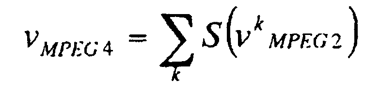
In the foregoing section 2), the motion vector candidates
to be used in the MPEG-4 INTER and INTER4V modes have been
selected. Then, from among these modes and the remaining
possible coding modes, INTRA mode and SKIP mode, the mode with
the highest coding efficiency is selected (steps ST3-ST11). As
a result, the final coding mode and motion vectors are decided.
The processing is carried out by the coding parameter deciding
section 10B. The processing by the coding parameter deciding
section 10B from now on is in conformity with the section 3)
of the foregoing embodiment 1. In this case, however, the
reference picture the motion prediction uses is a local decoded
picture of the MPEG-4 coded frame immediately previous to the
current target frame to be coded.
With the foregoing procedure, the present embodiment 2 can
select the optimum mode and the motion vectors associated with
it from among all the possible coding modes in the MPEG-4 coding
even in the transcoding that carries out temporal resolution
(frame rate conversion) involving the P frame decimation.
In particular, the present embodiment 2 simplifies the
motion vector detection with a large computational load even
in the transcoder that carries out the P frame decimation.
Accordingly, it can improve the quality of the video transcoding
from MPEG-2 to MPEG-4 as compared with the conventional simple
motion vector reusing method.
Although the foregoing description is made by way of example
using the MPEG-4 simple profile, the transcoder with the present
configuration is also applicable to all the MPEG-4 simple profile
compliant multi-mode coding schemes such as the MPEG-4 advanced
simple profile and a case supporting the motion prediction option
described in Annex F of ITU-T H.263. The present invention is
applicable to transcoding in general targeted for MC + DCT video
coding schemes.
As described above, the video data converter and video data
converting method in accordance with the present invention are
applicable to those requiring improvement in transcode video
quality by a small amount of computation, when carrying out a
variety of conversions of video compression data in conformity
with various video compression-decompression schemes based on
international standards.
Claims (8)
- A video data converter for converting input video coded data based on a first video coding scheme to video coded data based on a second video coding scheme, said first video coding scheme carrying out coding by dividing each frame of a video signal into specified segments and by selecting coding parameters including a motion vector for each specified segment, and said second video coding scheme carrying out coding by dividing each frame of the video signal into specified segments and by selecting coding parameters for each specified segment, said video data converter comprising:a motion vector mapping section for generating a motion vector candidate to be used for each specified segment of the second video coding scheme from the motion vector in the coding parameters of each specified segment of the first video coding scheme; anda coding parameter deciding section for deciding a motion vector to be used in the second video coding scheme from among the generated motion vector candidates in the second video coding scheme according to a prediction error estimation value that estimates a prediction efficiency when using the motion vector candidates and according to a value that estimates a motion vector rate when using the motion vector candidates.
- The video data converter according to claim 1, wherein said motion vector mapping section generates the motion vector candidates by a number of types of motion prediction that are possessed by the second video coding scheme.
- The video data converter according to claim 1, further comprising:wherein said coding parameter deciding section makes a decision as a coding mode to be used in the second video coding scheme by selecting, when deciding the coding mode, one of two methods of forcedly deciding the coding mode to be used in each of the specified segments in the second video coding scheme according to the coding mode estimated by said coding mode estimator, and of deciding the coding mode to be used in each of the specified segments in the second video coding scheme according to the prediction error estimation value and an estimated rate of the motion vector.a coding mode estimator for estimating a coding mode for each of the specified segments in the second video coding scheme according to a coding mode in the coding parameters of each of the specified segments in the first video coding scheme,
- The video data converter according to claim 1, further comprising a spatial resolution converter for down-converting spatial resolution of the video data coded in accordance with the first video coding scheme to half resolution in both horizontal and vertical directions.
- The video data converter according to claim 1, further comprising a temporal resolution converter for implementing temporal resolution of the video data coded in accordance with the first video coding scheme by decimating a frame not used for inter-frame motion prediction.
- The video data converter according to claim 3, further comprising:a temporal resolution converter for implementing temporal resolution of video data coded in accordance with the first video coding scheme by decimating frames including a frame used for inter-frame motion prediction, whereinsaid motion vector mapping section, when the frame used for the inter-frame motion prediction is decimated, decides a motion vector candidate to be used by the second video coding scheme by using the motion vector in the frame decimated, andsaid coding parameter deciding section, when the frame used for the inter-frame motion prediction is decimated, decides the coding mode to be used in the second video coding scheme by using the coding mode in the frame decimated.
- The video data converter according to claim 1, wherein said first video coding scheme is an MPEG-2 video coding scheme specified in ISO/IEC 13818-2, and said second video coding scheme is an MPEG-4 video coding scheme specified in ISO/IEC 14496-2.
- A video data converting method of converting input video coded data based on a first video coding scheme to video coded data based on a second video coding scheme, said first video coding scheme carrying out coding by dividing each frame of a video signal into specified segments and by selecting part of coding parameters for each specified segment, and said second video coding scheme carrying out coding by dividing each frame of the video signal into specified segments and by selecting part of coding parameters for each specified segment, said video data converting method comprising the steps of:generating a motion vector candidate to be used for each specified segment of the second video coding scheme from a motion vector in the coding parameters of each specified segment of the first video coding scheme; anddeciding a motion vector to be used in the second video coding scheme from among the generated motion vector candidates in the second video coding scheme according to at least one of a prediction error estimation value that estimates a prediction efficiency when using the motion vector candidates and according to a value that estimates a motion vector rate when using the motion vector candidates.
Applications Claiming Priority (3)
| Application Number | Priority Date | Filing Date | Title |
|---|---|---|---|
| JP2002112860 | 2002-04-16 | ||
| JP2002112860A JP4193406B2 (en) | 2002-04-16 | 2002-04-16 | Video data conversion apparatus and video data conversion method |
| PCT/JP2003/004529 WO2003088676A1 (en) | 2002-04-16 | 2003-04-09 | Video data conversion device and video data conversion method |
Publications (2)
| Publication Number | Publication Date |
|---|---|
| EP1475971A1 true EP1475971A1 (en) | 2004-11-10 |
| EP1475971A4 EP1475971A4 (en) | 2010-03-03 |
Family
ID=29243335
Family Applications (1)
| Application Number | Title | Priority Date | Filing Date |
|---|---|---|---|
| EP03746441A Withdrawn EP1475971A4 (en) | 2002-04-16 | 2003-04-09 | METHOD AND DEVICE FOR CONVERTING VIDEO DATA |
Country Status (6)
| Country | Link |
|---|---|
| US (1) | US7526027B2 (en) |
| EP (1) | EP1475971A4 (en) |
| JP (1) | JP4193406B2 (en) |
| KR (1) | KR100719647B1 (en) |
| CN (1) | CN100353769C (en) |
| WO (1) | WO2003088676A1 (en) |
Cited By (5)
| Publication number | Priority date | Publication date | Assignee | Title |
|---|---|---|---|---|
| EP1662800A1 (en) * | 2004-11-30 | 2006-05-31 | Humax Co., Ltd. | Image down-sampling transcoding method and device |
| WO2007125458A3 (en) * | 2006-04-27 | 2008-01-10 | Koninkl Philips Electronics Nv | Method and apparatus for encoding/transcoding and decoding |
| WO2011071754A1 (en) * | 2009-12-11 | 2011-06-16 | General Instrument Corporation | Mpeg video resolution reduction system |
| CN101218830B (en) * | 2005-07-22 | 2011-10-12 | 三菱电机株式会社 | Image encoding device and method, and image decoding device and method |
| EP1662799A3 (en) * | 2004-11-30 | 2012-05-30 | Humax Co., Ltd. | Video down-sampling transcoding method and device |
Families Citing this family (63)
| Publication number | Priority date | Publication date | Assignee | Title |
|---|---|---|---|---|
| HUP0301368A3 (en) * | 2003-05-20 | 2005-09-28 | Amt Advanced Multimedia Techno | Method and equipment for compressing motion picture data |
| JP4470431B2 (en) * | 2003-10-01 | 2010-06-02 | ソニー株式会社 | Data processing apparatus and method |
| US7483577B2 (en) * | 2004-03-02 | 2009-01-27 | Mitsubishi Electric Research Laboratories, Inc. | System and method for joint de-interlacing and down-sampling using adaptive frame and field filtering |
| US20050201469A1 (en) * | 2004-03-11 | 2005-09-15 | John Sievers | Method and apparatus for improving the average image refresh rate in a compressed video bitstream |
| KR101196429B1 (en) * | 2004-03-12 | 2012-11-01 | 삼성전자주식회사 | Video transcoding method and apparatus, and motion vector interpolation method |
| US20050232497A1 (en) * | 2004-04-15 | 2005-10-20 | Microsoft Corporation | High-fidelity transcoding |
| KR100681252B1 (en) * | 2004-10-02 | 2007-02-09 | 삼성전자주식회사 | Estimation of output macroblock mode and output motion vector for transcoding, and transcoder using the same |
| US8155191B2 (en) * | 2004-11-04 | 2012-04-10 | Thomson Licensing | Method and apparatus for fast mode decision of B-frames in a video encoder |
| KR100718468B1 (en) | 2004-11-30 | 2007-05-16 | 주식회사 휴맥스 | Method and device for video down-sampling transcoding |
| US7933335B2 (en) | 2004-11-30 | 2011-04-26 | Panasonic Corporation | Moving picture conversion apparatus |
| KR100718467B1 (en) | 2004-11-30 | 2007-05-16 | 주식회사 휴맥스 | Method and device for video down-sampling transcoding |
| KR101147744B1 (en) * | 2005-02-22 | 2012-05-25 | 엘지전자 주식회사 | Method and Apparatus of video transcoding and PVR of using the same |
| JP4604805B2 (en) * | 2005-04-12 | 2011-01-05 | Kddi株式会社 | Video information conversion apparatus and program |
| JP4682102B2 (en) * | 2005-09-02 | 2011-05-11 | キヤノン株式会社 | Image coding apparatus and image coding method |
| JP4600997B2 (en) * | 2005-11-08 | 2010-12-22 | Kddi株式会社 | Encoding method converter |
| KR100801974B1 (en) | 2005-12-08 | 2008-02-12 | 한국전자통신연구원 | Low cost motion estimation device and motion estimation method |
| US7944965B2 (en) * | 2005-12-19 | 2011-05-17 | Seiko Epson Corporation | Transform domain based distortion cost estimation |
| JP2007228400A (en) * | 2006-02-24 | 2007-09-06 | Mitsubishi Electric Corp | Video converter |
| CN101455087B (en) * | 2006-05-24 | 2011-01-12 | 松下电器产业株式会社 | Image encoding device, image encoding method, and integrated circuit for image encoding |
| TWI348651B (en) * | 2006-06-09 | 2011-09-11 | Via Tech Inc | A system for reducing bandwidth requirements for transferring graphics data and its related method |
| JP4245026B2 (en) | 2006-09-20 | 2009-03-25 | 株式会社豊田中央研究所 | Coating film removal method and coating member regeneration method |
| JP2008109637A (en) * | 2006-09-25 | 2008-05-08 | Toshiba Corp | Video encoding apparatus and method |
| FR2907989B1 (en) * | 2006-10-27 | 2009-01-16 | Actimagine Sarl | METHOD AND DEVICE FOR OPTIMIZING THE COMPRESSION OF A VIDEO STREAM |
| JP4882948B2 (en) * | 2007-10-04 | 2012-02-22 | ソニー株式会社 | Image processing apparatus and method, and program |
| US8098732B2 (en) * | 2007-10-10 | 2012-01-17 | Sony Corporation | System for and method of transcoding video sequences from a first format to a second format |
| US8457958B2 (en) * | 2007-11-09 | 2013-06-04 | Microsoft Corporation | Audio transcoder using encoder-generated side information to transcode to target bit-rate |
| KR101377527B1 (en) | 2008-10-14 | 2014-03-25 | 에스케이 텔레콤주식회사 | Method and Apparatus for Encoding and Decoding Motion Vector in Plural Number of Reference Pictures and Video Encoding/Decoding Method and Apparatus Using Same |
| US8311115B2 (en) * | 2009-01-29 | 2012-11-13 | Microsoft Corporation | Video encoding using previously calculated motion information |
| US8396114B2 (en) * | 2009-01-29 | 2013-03-12 | Microsoft Corporation | Multiple bit rate video encoding using variable bit rate and dynamic resolution for adaptive video streaming |
| US8270473B2 (en) * | 2009-06-12 | 2012-09-18 | Microsoft Corporation | Motion based dynamic resolution multiple bit rate video encoding |
| JP5378939B2 (en) * | 2009-10-02 | 2013-12-25 | 日立コンシューマエレクトロニクス株式会社 | Image encoding method, image decoding method, image encoding device, image decoding device, and program |
| EP2355511A1 (en) * | 2009-12-21 | 2011-08-10 | Alcatel Lucent | Method and arrangement for jointly encoding a plurality of video streams |
| US8315310B2 (en) * | 2010-01-08 | 2012-11-20 | Research In Motion Limited | Method and device for motion vector prediction in video transcoding using full resolution residuals |
| US8340188B2 (en) * | 2010-01-08 | 2012-12-25 | Research In Motion Limited | Method and device for motion vector estimation in video transcoding using union of search areas |
| US8559519B2 (en) * | 2010-01-08 | 2013-10-15 | Blackberry Limited | Method and device for video encoding using predicted residuals |
| US8358698B2 (en) * | 2010-01-08 | 2013-01-22 | Research In Motion Limited | Method and device for motion vector estimation in video transcoding using full-resolution residuals |
| US20110170608A1 (en) * | 2010-01-08 | 2011-07-14 | Xun Shi | Method and device for video transcoding using quad-tree based mode selection |
| US9819358B2 (en) * | 2010-02-19 | 2017-11-14 | Skype | Entropy encoding based on observed frequency |
| US8913661B2 (en) * | 2010-02-19 | 2014-12-16 | Skype | Motion estimation using block matching indexing |
| US9313526B2 (en) * | 2010-02-19 | 2016-04-12 | Skype | Data compression for video |
| US9609342B2 (en) * | 2010-02-19 | 2017-03-28 | Skype | Compression for frames of a video signal using selected candidate blocks |
| US9078009B2 (en) * | 2010-02-19 | 2015-07-07 | Skype | Data compression for video utilizing non-translational motion information |
| US9049450B2 (en) | 2010-04-05 | 2015-06-02 | Samsung Electronics Co., Ltd. | Method and apparatus for encoding video based on internal bit depth increment, and method and apparatus for decoding video based on internal bit depth increment |
| KR20110112168A (en) * | 2010-04-05 | 2011-10-12 | 삼성전자주식회사 | Video encoding method and apparatus therefor based on internal bit depth extension, Video decoding method and apparatus therefor based on internal bit depth extension |
| US8982961B2 (en) | 2010-04-05 | 2015-03-17 | Samsung Electronics Co., Ltd. | Method and apparatus for encoding video by using transformation index, and method and apparatus for decoding video by using transformation index |
| WO2011126277A2 (en) | 2010-04-05 | 2011-10-13 | Samsung Electronics Co., Ltd. | Low complexity entropy-encoding/decoding method and apparatus |
| CN102823248B (en) | 2010-04-08 | 2015-06-24 | 株式会社东芝 | Image encoding method and image encoding device |
| US8705616B2 (en) | 2010-06-11 | 2014-04-22 | Microsoft Corporation | Parallel multiple bitrate video encoding to reduce latency and dependences between groups of pictures |
| CN101964910B (en) * | 2010-08-20 | 2012-08-22 | 华中科技大学 | Video spatial resolution conversion method based on code-rate type transcoding assistance |
| US8755438B2 (en) * | 2010-11-29 | 2014-06-17 | Ecole De Technologie Superieure | Method and system for selectively performing multiple video transcoding operations |
| US9749657B2 (en) | 2011-01-21 | 2017-08-29 | Sharp Kabushiki Kaisha | Buffer compression for motion vector competition |
| US20120275502A1 (en) * | 2011-04-26 | 2012-11-01 | Fang-Yi Hsieh | Apparatus for dynamically adjusting video decoding complexity, and associated method |
| US9591318B2 (en) | 2011-09-16 | 2017-03-07 | Microsoft Technology Licensing, Llc | Multi-layer encoding and decoding |
| US11089343B2 (en) | 2012-01-11 | 2021-08-10 | Microsoft Technology Licensing, Llc | Capability advertisement, configuration and control for video coding and decoding |
| JP6421426B2 (en) | 2014-03-26 | 2018-11-14 | 沖電気工業株式会社 | Encoding method conversion apparatus and program |
| JP6291971B2 (en) * | 2014-03-31 | 2018-03-14 | 富士通株式会社 | Encoding apparatus, encoding method, and encoding program |
| ES3063951T3 (en) * | 2014-10-31 | 2026-04-21 | Samsung Electronics Co Ltd | Device for decoding motion vector |
| US10462459B2 (en) * | 2016-04-14 | 2019-10-29 | Mediatek Inc. | Non-local adaptive loop filter |
| JP6574148B2 (en) * | 2016-07-13 | 2019-09-11 | Kddi株式会社 | Transcoding system, transcoding method, computer-readable recording medium, and encoding apparatus |
| JP6977422B2 (en) | 2017-09-13 | 2021-12-08 | 株式会社Jvcケンウッド | Transcoding device, transcoding method and transcoding program |
| US10764603B2 (en) | 2018-12-31 | 2020-09-01 | Alibaba Group Holding Limited | Resolution-adaptive video coding |
| CN114009012B (en) * | 2019-04-24 | 2024-09-03 | 内维尔明德资本有限责任公司 | Content distribution method, image capture and processing system, playback system, method of operating a playback system, and computer readable medium |
| EP3997879A4 (en) | 2019-07-09 | 2023-03-22 | Alibaba Group Holding Limited | ADAPTIVE RESOLUTION VIDEO CODING |
Family Cites Families (21)
| Publication number | Priority date | Publication date | Assignee | Title |
|---|---|---|---|---|
| JPH06105299A (en) | 1992-09-22 | 1994-04-15 | Casio Comput Co Ltd | Video compression device |
| CA2157494C (en) * | 1993-03-26 | 1999-08-24 | David Geoffrey Morrison | A transcoder |
| NL9301358A (en) * | 1993-08-04 | 1995-03-01 | Nederland Ptt | Transcoder. |
| JPH07264597A (en) | 1994-03-18 | 1995-10-13 | Nippon Telegr & Teleph Corp <Ntt> | Motion compensation method |
| DE4416967A1 (en) * | 1994-05-13 | 1995-11-16 | Thomson Brandt Gmbh | Method and device for transcoding bit streams with video data |
| JP3778960B2 (en) | 1994-06-29 | 2006-05-24 | 株式会社東芝 | Video coding method and apparatus |
| JP3058028B2 (en) | 1994-10-31 | 2000-07-04 | 三菱電機株式会社 | Image encoded data re-encoding device |
| JPH09322176A (en) | 1995-12-20 | 1997-12-12 | Sanyo Electric Co Ltd | Encoding mode selecting method, moving image encoding device, encoding method, recording method and transmitting method |
| JPH09322173A (en) | 1996-05-27 | 1997-12-12 | Nippon Telegr & Teleph Corp <Ntt> | Method and apparatus for extracting moving image telop |
| JP3150627B2 (en) | 1996-10-04 | 2001-03-26 | 日本電信電話株式会社 | Re-encoding method of decoded signal |
| FR2757295B1 (en) * | 1996-12-13 | 2001-05-18 | Sgs Thomson Microelectronics | METHOD AND DEVICE FOR ESTIMATING MOTION OF MOVING IMAGE PORTIONS |
| JPH10336672A (en) * | 1997-05-30 | 1998-12-18 | Oki Electric Ind Co Ltd | Encoding system converter and motion vector detection method therefor |
| DE69803195T2 (en) * | 1997-11-27 | 2002-08-29 | British Telecommunications P.L.C., London | CODE IMPLEMENTATION |
| JPH11243551A (en) | 1997-12-25 | 1999-09-07 | Mitsubishi Electric Corp | Motion compensation device and video encoding device and method |
| US6058143A (en) * | 1998-02-20 | 2000-05-02 | Thomson Licensing S.A. | Motion vector extrapolation for transcoding video sequences |
| JP3855522B2 (en) * | 1999-02-23 | 2006-12-13 | 松下電器産業株式会社 | Video converter |
| JP4426689B2 (en) * | 1999-02-25 | 2010-03-03 | パナソニック株式会社 | Conversion method and apparatus for moving picture coding system |
| US6625211B1 (en) * | 1999-02-25 | 2003-09-23 | Matsushita Electric Industrial Co., Ltd. | Method and apparatus for transforming moving picture coding system |
| JP2001268579A (en) | 2000-03-23 | 2001-09-28 | Sanyo Electric Co Ltd | Moving image re-encoder |
| US6647061B1 (en) * | 2000-06-09 | 2003-11-11 | General Instrument Corporation | Video size conversion and transcoding from MPEG-2 to MPEG-4 |
| JP2002010267A (en) * | 2000-06-26 | 2002-01-11 | Sony Corp | Apparatus and method for converting motion vector |
-
2002
- 2002-04-16 JP JP2002112860A patent/JP4193406B2/en not_active Expired - Fee Related
-
2003
- 2003-04-09 CN CNB038055872A patent/CN100353769C/en not_active Expired - Fee Related
- 2003-04-09 KR KR20047016448A patent/KR100719647B1/en not_active Expired - Fee Related
- 2003-04-09 US US10/501,897 patent/US7526027B2/en not_active Expired - Fee Related
- 2003-04-09 EP EP03746441A patent/EP1475971A4/en not_active Withdrawn
- 2003-04-09 WO PCT/JP2003/004529 patent/WO2003088676A1/en not_active Ceased
Cited By (7)
| Publication number | Priority date | Publication date | Assignee | Title |
|---|---|---|---|---|
| EP1662800A1 (en) * | 2004-11-30 | 2006-05-31 | Humax Co., Ltd. | Image down-sampling transcoding method and device |
| US8059720B2 (en) | 2004-11-30 | 2011-11-15 | Humax Co., Ltd. | Image down-sampling transcoding method and device |
| EP1662799A3 (en) * | 2004-11-30 | 2012-05-30 | Humax Co., Ltd. | Video down-sampling transcoding method and device |
| CN101218830B (en) * | 2005-07-22 | 2011-10-12 | 三菱电机株式会社 | Image encoding device and method, and image decoding device and method |
| CN102176754B (en) * | 2005-07-22 | 2013-02-06 | 三菱电机株式会社 | Image encoding device and method and image decoding device and method |
| WO2007125458A3 (en) * | 2006-04-27 | 2008-01-10 | Koninkl Philips Electronics Nv | Method and apparatus for encoding/transcoding and decoding |
| WO2011071754A1 (en) * | 2009-12-11 | 2011-06-16 | General Instrument Corporation | Mpeg video resolution reduction system |
Also Published As
| Publication number | Publication date |
|---|---|
| CN1640149A (en) | 2005-07-13 |
| JP4193406B2 (en) | 2008-12-10 |
| CN100353769C (en) | 2007-12-05 |
| WO2003088676A1 (en) | 2003-10-23 |
| EP1475971A4 (en) | 2010-03-03 |
| KR100719647B1 (en) | 2007-05-17 |
| JP2003309851A (en) | 2003-10-31 |
| US7526027B2 (en) | 2009-04-28 |
| US20050041740A1 (en) | 2005-02-24 |
| KR20040105872A (en) | 2004-12-16 |
Similar Documents
| Publication | Publication Date | Title |
|---|---|---|
| US7526027B2 (en) | Video data converter and video data converting method | |
| US5801779A (en) | Rate control with panic mode | |
| US5761398A (en) | Three stage hierarchal motion vector determination | |
| US20120076203A1 (en) | Video encoding device, video decoding device, video encoding method, and video decoding method | |
| US20070098067A1 (en) | Method and apparatus for video encoding/decoding | |
| US20040120398A1 (en) | System and method for adaptive field and frame video encoding using rate-distortion characteristics | |
| US7088772B2 (en) | Method and apparatus for updating motion vector memories | |
| US9172973B2 (en) | Method and system for motion estimation in a video encoder | |
| KR20040077774A (en) | Image information coding device and method and image information decoding device and method | |
| US7092442B2 (en) | System and method for adaptive field and frame video encoding using motion activity | |
| JP2002152759A (en) | Image information conversion apparatus and image information conversion method | |
| US6205178B1 (en) | Method and synthesizing a predicted image, video coding device and video coding method | |
| US7822116B2 (en) | Method and system for rate estimation in a video encoder | |
| JP2005203905A (en) | Image coding apparatus, image coding method, and image coding program | |
| US20060008007A1 (en) | Adaptive coding method or device | |
| US20060239347A1 (en) | Method and system for scene change detection in a video encoder | |
| US7991048B2 (en) | Device and method for double-pass encoding of a video data stream | |
| JP5649296B2 (en) | Image encoding device | |
| US7236529B2 (en) | Methods and systems for video transcoding in DCT domain with low complexity | |
| EP0987903A1 (en) | Method for image compression and device for implementing the method | |
| US6480544B1 (en) | Encoding apparatus and encoding method | |
| US9094716B2 (en) | Methods for coding and decoding a block of picture data, devices for coding and decoding implementing said methods | |
| US7133448B2 (en) | Method and apparatus for rate control in moving picture video compression | |
| EP2404448B1 (en) | Method for predicting a block of image data, decoding and coding devices implementing said method | |
| JPH0775095A (en) | Rate control circuit |
Legal Events
| Date | Code | Title | Description |
|---|---|---|---|
| PUAI | Public reference made under article 153(3) epc to a published international application that has entered the european phase |
Free format text: ORIGINAL CODE: 0009012 |
|
| 17P | Request for examination filed |
Effective date: 20040813 |
|
| AK | Designated contracting states |
Kind code of ref document: A1 Designated state(s): AT BE BG CH CY CZ DE DK EE ES FI FR GB GR HU IE IT LI LU MC NL PT RO SE SI SK TR |
|
| RAP1 | Party data changed (applicant data changed or rights of an application transferred) |
Owner name: MITSUBISHI DENKI KABUSHIKI KAISHA |
|
| A4 | Supplementary search report drawn up and despatched |
Effective date: 20100129 |
|
| STAA | Information on the status of an ep patent application or granted ep patent |
Free format text: STATUS: THE APPLICATION HAS BEEN WITHDRAWN |
|
| 18W | Application withdrawn |
Effective date: 20100331 |