EP1475750A2 - Method and apparatus for image reconstruction and X-Ray CT imaging apparatus - Google Patents
Method and apparatus for image reconstruction and X-Ray CT imaging apparatus Download PDFInfo
- Publication number
- EP1475750A2 EP1475750A2 EP04251882A EP04251882A EP1475750A2 EP 1475750 A2 EP1475750 A2 EP 1475750A2 EP 04251882 A EP04251882 A EP 04251882A EP 04251882 A EP04251882 A EP 04251882A EP 1475750 A2 EP1475750 A2 EP 1475750A2
- Authority
- EP
- European Patent Office
- Prior art keywords
- data
- filtering
- continuous
- projection data
- projection
- Prior art date
- Legal status (The legal status is an assumption and is not a legal conclusion. Google has not performed a legal analysis and makes no representation as to the accuracy of the status listed.)
- Granted
Links
Images



Classifications
-
- A—HUMAN NECESSITIES
- A61—MEDICAL OR VETERINARY SCIENCE; HYGIENE
- A61B—DIAGNOSIS; SURGERY; IDENTIFICATION
- A61B6/00—Apparatus or devices for radiation diagnosis; Apparatus or devices for radiation diagnosis combined with radiation therapy equipment
- A61B6/02—Arrangements for diagnosis sequentially in different planes; Stereoscopic radiation diagnosis
- A61B6/03—Computed tomography [CT]
-
- G—PHYSICS
- G06—COMPUTING OR CALCULATING; COUNTING
- G06T—IMAGE DATA PROCESSING OR GENERATION, IN GENERAL
- G06T12/00—Tomographic reconstruction from projections
- G06T12/10—Image preprocessing, e.g. calibration, positioning of sources or scatter correction
-
- A—HUMAN NECESSITIES
- A61—MEDICAL OR VETERINARY SCIENCE; HYGIENE
- A61B—DIAGNOSIS; SURGERY; IDENTIFICATION
- A61B6/00—Apparatus or devices for radiation diagnosis; Apparatus or devices for radiation diagnosis combined with radiation therapy equipment
- A61B6/52—Devices using data or image processing specially adapted for radiation diagnosis
- A61B6/5258—Devices using data or image processing specially adapted for radiation diagnosis involving detection or reduction of artifacts or noise
-
- G—PHYSICS
- G06—COMPUTING OR CALCULATING; COUNTING
- G06T—IMAGE DATA PROCESSING OR GENERATION, IN GENERAL
- G06T2211/00—Image generation
- G06T2211/40—Computed tomography
- G06T2211/448—Computed tomography involving metal artefacts, streaking artefacts, beam hardening or photon starvation
-
- Y—GENERAL TAGGING OF NEW TECHNOLOGICAL DEVELOPMENTS; GENERAL TAGGING OF CROSS-SECTIONAL TECHNOLOGIES SPANNING OVER SEVERAL SECTIONS OF THE IPC; TECHNICAL SUBJECTS COVERED BY FORMER USPC CROSS-REFERENCE ART COLLECTIONS [XRACs] AND DIGESTS
- Y10—TECHNICAL SUBJECTS COVERED BY FORMER USPC
- Y10S—TECHNICAL SUBJECTS COVERED BY FORMER USPC CROSS-REFERENCE ART COLLECTIONS [XRACs] AND DIGESTS
- Y10S378/00—X-ray or gamma ray systems or devices
- Y10S378/901—Computer tomography program or processor
Definitions
- the present invention is related to a radiological tomographic imaging apparatus such as an X-ray CT (computed tomography).
- a radiological tomographic imaging apparatus such as an X-ray CT (computed tomography).
- the X-ray CT consists of a beam emitter system and detector system, i.e., X-ray emitter system and detector system, which are opposedly placed at both side of a subject, and are rotated about the subject while emitting an X-ray beam to the subject (scanning).
- the X-ray beam transmitted through the subject is detected by the detector system around the subject in a plurality of view directions to measure the data projected through the subject by the X-ray beam in each direction.
- a tomographic image of the subject can be reconstructed based on the projected data.
- the projection data from the subject may be preprocessed, and thus preprocessed projection data may be used to reconstruct an image according to for example a filtered back projection method.
- projection data of the subject will be filtered as needed for image reconstruction and the filtered projection data will be back projected to reconstruct an image.
- the filtering a variety of filters can be selected according to the diagnostic purpose and the subject lesion.
- the filtering consists of FFT (fast Fourier transfer) of the data, multiplication by the selected filter with the FFT data, and IFFT (inverse FFT).
- FFT fast Fourier transfer
- IFFT inverse FFT
- high frequency noises in the projection data may be eliminated during the filtering.
- the noise reduction technique on high frequency noises included in the projection data can be seen for example in JP-A-2000-83946
- the value in the detected projection data in the part corresponding to the foreign matter may abruptly change, to become a part non-continuous from other parts. This is because the X-ray absorption rate of metals is very high.
- data value of the part including the foreign matter may contain high frequency components, which value may abruptly change.
- the data value in this part may become changed so that the projection data after the invert FFT may have some distortion such as undershoot and overshoot.
- the present invention seeks to provide a method and apparatus for image reconstruction and X-ray CT imaging apparatus, allowing decreasing the streak artifact in the reconstructed image due to the existence of foreign matter of high X-ray absorption rate such as metals.
- the image reconstruction apparatus uses the projection data obtained by detecting the radiation beam transmitted through a subject with a plurality of radiation beam detector elements to reconstruct the tomographic image of the subject, which apparatus incorporates a non-continuous data processing means, for performing a predetermined filtering to data except for any discrete area including data of non-continuous value, among the projection data arranged in the order of sequence of said radiation beam detector elements array, to reassemble said non-continuous data of discrete area with the data having said filtering undergone to provide the projection data for reconstructing said tomographic image.
- a non-continuous data processing means for performing a predetermined filtering to data except for any discrete area including data of non-continuous value, among the projection data arranged in the order of sequence of said radiation beam detector elements array, to reassemble said non-continuous data of discrete area with the data having said filtering undergone to provide the projection data for reconstructing said tomographic image.
- said non-continuous data processing means includes: a separator means for isolating any non-continuous data in said discrete area from said projection data, converting said isolated non-continuous projection data to continuous data so as for the value to change consistently, and serving only those continuous data for said filtering; and a synthesizer means for synthesizing said continuous data derived from said filtering and said non-continuous data of discrete area to reassemble the projection data to be provided to said image reconstruction means.
- the image reconstruction apparatus may comprise said non-continuous data processing means, composed of: an extractor means, for extracting said discrete areas based on the difference between the projection data having said filtering undergo and the projection data not having said filtering undergo; and a synthesizer means for substituting the extracted non-continuous data of said discrete area in the projection data having said filtering undergo with the projection data not having the filtering to prepare the projection data to be provided to said image reconstructor means.
- said non-continuous data processing means composed of: an extractor means, for extracting said discrete areas based on the difference between the projection data having said filtering undergo and the projection data not having said filtering undergo; and a synthesizer means for substituting the extracted non-continuous data of said discrete area in the projection data having said filtering undergo with the projection data not having the filtering to prepare the projection data to be provided to said image reconstructor means.
- An image reconstruction method in accordance with the present invention uses the projection data obtained by detecting the radiation beam transmitted through a subject with a plurality of radiation beam detector elements to reconstruct the tomographic image of said subject, which method comprises: a step for performing a predetermined filtering to data except for any discrete area including data of non-continuous value, among the projection data arranged in the order of sequence of said radiation beam detector elements array, to reassemble said non-continuous data of discrete area with the data having said filtering undergone to provide the projection data for reconstructing said tomographic image.
- a radiographic tomography imaging apparatus in accordance with the present invention may comprise: a radiation detector, having a radiation emitter means and a plurality of radiation detector elements placed opposedly on the both sides of a subject; and an image reconstruction apparatus, for reconstructing a tomographic image of said subject based on the projection data obtained by detecting the radiation transmitted through said subject by said plurality of radiation detector elements; in which said image reconstruction apparatus comprises a non-continuous data processing means, for performing a predetermined filtering to data except for any discrete area including data of non-continuous value, among the projection data arranged in the order of sequence of said radiation beam detector elements array, to reassemble said non-continuous data of discrete area with the data having said filtering undergone to provide the projection data for reconstructing said tomographic image.
- any non-continuous data included in the projection data may be used as is without filtering.
- the high frequency component contained in the non-continuous data thereby may not be distorted, resulting in a more accurate reconstruction of an image in the non-continuous parts.
- a method and apparatus of image reconstruction and a radiographic tomography imaging apparatus are provided, which allows decreasing the streak artifact developed in the reconstructed image due to the existence of a foreign matter, such as a metal in the subject, which has a high X-ray absorption rate.
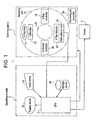
- FIG. 1 there is shown a schematic block diagram illustrating an overview of an X-ray CT apparatus as a preferred embodiment of a radiographic tomography imaging apparatus in accordance with the present invention.
- the X-ray CT 1 may have a scanning gantry 2, an operating console 3, and an imaging table (cradle) 4.
- the scanning gantry 2 may include an X-ray tube 21.
- the X-ray tube 21 may emit an X-ray beam not shown in the figure, which passes through a collimator 22, which shapes the beam into an X-ray beam of sector form to be incident into an X-ray detector 23.
- the X-ray detector 23 may include a plurality of X-ray detector elements, arranged as an array oriented in the direction of sector of fan beam.
- the X-ray detector 23 may be a multichannel detector having a plurality of X-ray detecting elements arranged in an array.
- the X-ray detector 23 may form an X-ray incident plane of cylindrical concave shape.
- the X-ray detector 23 may be formed for example by a combination of scintillator and photodiode.
- the X-ray detector in accordance with the present invention may not be intended to be limited thereto, any other forms of detectors can be used instead, such as semiconductor X-ray detector elements using for example Cadmium-Tellurium (CdTe), or an ion chamber type X-ray detector elements using Xenon (Xe) gas.
- the X-ray detector 23 is connected to a data collector unit 24.
- the data collector unit 24 is used to gather detected data from each X-ray detector element.
- the emission of X-ray from the X-ray tube 21 is controlled by an X-ray controller 25.
- the connection between the X-ray tube 21 and the X-ray controller 25 as well as the connection between the collimator 22 and a collimator controller 26 are not depicted in the figure.
- the collimator 22 is controlled by the collimator controller 26.
- a revolving unit 27 of the scanning gantry 2 incorporates the X-ray tube 21, the collimator 22, the X-ray detector 23, the data collector unit 24, the X-ray controller 25 and the collimator controller 26.
- the subject to be images will be carried on a cradle in a bore 29 located in the center of the revolving unit 27.
- the revolving unit 27 will rotate under the control of a revolving unit controller 28, emit X-ray beam from the X-ray tube 21, and detect the X-ray beam transmitted through the subject at the X-ray detector 23 as the projection information for each view.
- the connection between the revolving unit 27 and the revolving unit controller 28 is not shown in the figure.
- the operation console 6 may have a central processing unit (CPU) 31, an input device 32, a display device 33, and a storage device 34.
- CPU central processing unit
- the CPU 31 and the storage device 34 constitute the image reconstructing apparatus in accordance with the present invention.
- the CPU 31 consists of for example a microprocessor and a memory.
- the CPU 31 may have at least the function of controlling the operation of the scanning gantry 2 to collect the projection data obtained by detecting the X-ray transmitted through the subject by the X-ray detector 23, and the function of reconstructing a tomographic image of the subject based on thus collected X-ray projection data, in accordance with the software stored in the storage device 34.
- the data collected at the data collector unit 24 will be input into the CPU 31 via a data collector buffer not shown in the figure, and the CPU 31 in turn uses the collected projection data to reconstruct an image.
- the image reconstruction processing by the CPU 31 will be described in greater details later.
- the display device 33 displays information such as information on the tomographic image and any other information output from the CPU 31.
- the input device 32 is manipulated by an operator to input to the CPU 31 various instructions and information. The operator will use the display device 33 and the input device 32 to operate the apparatus interactively.
- the X-ray tube 21 and the X-ray detector 23 are relatively moving in the scanning gantry 2 to scan the area to be imaged in the subject to collect the projection data of the subject in the data collector unit 24, and the projection data will be sent to the CPU 31, which in turn a tomographic image of the subject will be reconstructed.
- FIG. 2 there is shown an overview of an image reconstruction procedure take by the CPU 31.
- the image reconstruction by the CPU 31 may be conducted according to the filtered back projection method.
- the filtered back projection method itself is well known in the art and the detailed description thereof will be omitted.
- the image reconstruction by the CPU 31 may be composed of the non-continuous data processing, consisted of preprocessing (step ST1), separation (step ST2), filtering (step ST3), and synthesis (step ST4), and of the back projection processing (step ST5).
- step ST1 the projection data of the subject obtained from the data collector unit 24 are to be compensated for physically and electrically so as to reconstruct a normal image.
- FIG. 3 there is shown a schematic diagram illustrating the details of separation process (step ST2).
- (a) illustrates an exemplary projection data of the subject obtained from the data collector unit 24,
- (b) illustrates the projection data after separation performed, and
- (c) illustrates non-continuous data isolated.
- the data is in the sequence (order) of channel of the detector array in the X-ray detector 23.
- the non-continuous data herein is indicative of part of data that contains data that the value is different over a plurality of channels.
- the data value of the part corresponding to the foreign matter may abruptly changes, in the projection data dat_R.
- data value changes continuously and smoothly.
- non-continuous data dat_EX as the data from the discrete region that contains abruptly changing data value, in the projection data dat_R shown in Fig. 3 (a), the non-continuous data dat_EX may contain high frequency components when considering data value in the frequency domain.
- the high frequency components contained in the non-continuous data dat_EX also may be removed.
- step ST2 non-continuous data dat_EX will be isolated from the projection data dat_R, as shown in Fig. 3 (c).
- the continuous data dat_S may be used for the filtering.
- step ST3 at first the continuous data dat_S will be processed with FFT (fast Fourier Transform).
- the data will be filtered with a filter selected according to the diagnosis purpose or subject lesion.
- the filter used in the filtering may be appropriately selected so as to be best suited to the diagnostic purpose and lesion to be imaged, however the filter will eliminate the high frequency noise components contained in the continuous data dat_S, at the same time.
- Fig. 4 there is shown a graph illustrating the filter characteristics in the filtering (step ST3), where (a) is data prior to FFT, and (b) data after IFFT.
- non-continuous data dat_EX containing high frequency components is isolated so as to exclude from the object data to be processed. Any noises in the continuous data dat_S thereby will be removed by the filtering while at the same time no distortion occurs.
- step ST4 combines the isolated non-continuous data dat_EX and the filtered continuous data dat_S. Thus combined data will be served as data used for the image construction by the back projection (step ST5).
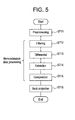
- FIG. 5 there is shown an overview of image reconstruction process in accordance with another preferred embodiment of a radiographic tomography imaging apparatus of the present invention.
- the image reconstruction process performed by the CPU 31 in accordance with the preferred embodiment may be composed of non-continuous data processing consisted of preprocessing (step ST11), filtering (step ST12), differentiation (step ST13), extraction (step ST14), and composition (step ST15), and of the back projection (step ST16).
- step ST11 The preprocessing (step ST11) is just similar to that performed in the first preferred embodiment.
- the processing is identical to that performed in the first preferred embodiment. More specifically, FFT (fast Fourier transform) is done on the projection data of the subject obtained from the data collector unit 24, then filtering with a filter selected according to the diagnostic purpose or object lesion, and finally recovering by IFFT (invert fast Fourier transform) on the filtered data.
- FFT fast Fourier transform
- IFFT invert fast Fourier transform
- FIG. 6 there is shown (a) an exemplary projection data prior to filtering, (b) an exemplary projection data after filtering, and (c) differential of projection data before and after the filtering.
- the projection data dat_B before filtering contains some noises, as well as a discrete region Ra that has data values non-continuously changing.
- this discrete region Ra may be resulted from the existence of a foreign matter, such as a metal, which has a high X-ray absorption rate.
- the differential processing may compute the differential between the projection data dat_B before filtering and projection data dat_A after filtering.
- the differential data as shown in Fig. 6 (c), may include noises contained in the projection data dat_B and distortion st developed by the filtering.
- the extraction processing may extract from the differential data as shown in Fig. 6 (c) discrete regions Rb and Rc. Those discrete regions Rb and Rc are regions in the projection data dat_B where the distortion st can be developed by the filtering.
- These discrete regions Rb and Rc can be extracted by defining a threshold and comparing the differential data with the predetermined threshold. It is important to note that the noises should have to be distinguished from the distortion st when comparing the differential data with the threshold.
- the distortion st exists over a plurality of channels, while on the other hand noises are likely to develop in a single channel. Since the signal level of the distortion st is different from the level of noises, the distinction between them may be easy.
- step ST15 the data in the discrete regions Rb and Rc extracted by the extraction step (step ST14) from within the projection data dat_A after filtering, will be substituted with the projection data dat_B before filtering.
- data with no distortion st developed is used for replacing the discrete regions Rb and Rc.
- the data thus composed is used for the image reconstruction by the back projection (step ST16).
- the discrete regions Rb and Rc are identified.
- data without filtering is applied to the discrete regions Rb and Rc. In this manner the streak artifacts caused by the filtering may be positively prevented from developing in the image reconstructed after the back projection.
- exemplary embodiments have been depicted which uses X-ray beam as radiation, the radiation may not be limited thereto.
- any radiation including the gamma ray can be used instead.
- the X-ray is the most preferable because of its widest assortment of practical means with respect to the generation, detection and control.
Landscapes
- Engineering & Computer Science (AREA)
- Health & Medical Sciences (AREA)
- Life Sciences & Earth Sciences (AREA)
- Medical Informatics (AREA)
- Physics & Mathematics (AREA)
- Biomedical Technology (AREA)
- Molecular Biology (AREA)
- Biophysics (AREA)
- Nuclear Medicine, Radiotherapy & Molecular Imaging (AREA)
- Optics & Photonics (AREA)
- Pathology (AREA)
- Radiology & Medical Imaging (AREA)
- Veterinary Medicine (AREA)
- Heart & Thoracic Surgery (AREA)
- High Energy & Nuclear Physics (AREA)
- Surgery (AREA)
- Animal Behavior & Ethology (AREA)
- General Health & Medical Sciences (AREA)
- Public Health (AREA)
- Computer Vision & Pattern Recognition (AREA)
- General Physics & Mathematics (AREA)
- Theoretical Computer Science (AREA)
- Apparatus For Radiation Diagnosis (AREA)
- Image Processing (AREA)
- Analysing Materials By The Use Of Radiation (AREA)
Abstract
Description
Claims (10)
- An image reconstruction apparatus, which uses the projection data obtained by detecting the radiation beam transmitted through a subject with a plurality of radiation beam detector elements to reconstruct the tomographic image of said subject, comprising a non-continuous data processing device, for performing a predetermined filtering to data except for any discrete area including data of non-continuous value, among the projection data arranged in the order of sequence of said radiation beam detector elements array, to reassemble said non-continuous data of discrete area with the data having said filtering undergone to provide the projection data for reconstructing said tomographic image.
- An image reconstruction method, which uses the projection data obtained by detecting the radiation beam transmitted through a subject with a plurality of radiation beam detector elements to reconstruct the tomographic image of said subject, comprising a step of performing a predetermined filtering to data except for any discrete area including data of non-continuous value, among the projection data arranged in the order of sequence of said radiation beam detector elements array, to reassemble said non-continuous data of discrete area with the data having said filtering undergone to provide the projection data for reconstructing said tomographic image.
- A radiographic tomography imaging apparatus, comprising:wherein:a radiation detector, having a radiation emitter device and a plurality of radiation detector elements placed opposedly on the both sides of a subject; andan image reconstruction apparatus, for reconstructing a tomographic image of said subject based on the projection data obtained by detecting the radiation transmitted through said subject by said plurality of radiation detector elements;said image reconstruction apparatus comprises a non-continuous data processing device, for performing a predetermined filtering to data except for any discrete area including data of non-continuous value, among the projection data arranged in the order of sequence of said radiation beam detector elements array, to reassemble said non-continuous data of discrete area with the data having said filtering undergone to provide the projection data for reconstructing said tomographic image.
- A radiographic tomography imaging apparatus, according to claim 3, wherein:said non-continuous data processing device includes:a separator device for isolating any non-continuous data in said discrete area from said projection data, converting said isolated non-continuous projection data to continuous data so as for the value to change consistently, and serving only those continuous data for said filtering; anda synthesizer device for synthesizing said continuous data derived from said filtering and said non-continuous data of discrete area to reassemble the projection data to be provided to said image reconstruction device.
- A radiographic tomography imaging apparatus, according to claim 3, wherein:said noncontinuous data processing device includes:an extractor device, for extracting said discrete areas based on the difference between the projection data having said filtering undergo and the projection data not having said filtering undergo; anda synthesizer device for substituting the extracted non-continuous data of said discrete area in the projection data having said filtering undergo with the projection data not having the filtering to prepare the projection data to be provided to said image reconstructor device.
- A radiographic tomography imaging apparatus, according to claim 3, wherein said radiation emitter device includes an X-ray tube.
- A radiographic tomography imaging apparatus, according to claim 6, further comprising a collimator for shaping the X-ray emitted from said X-ray tube into an X-ray beam of sector form.
- A radiographic tomography imaging apparatus, according to claim 3, wherein said radiation detector device is composed of an array of a plurality of X-ray detector elements.
- A radiographic tomography imaging apparatus according to claim 3, wherein said image reconstructor device uses the filtered back projection method.
- A radiographic tomography imaging apparatus according to claim 8, wherein said radiation detector device is composed of a combination of scintillator and photodiode.
Applications Claiming Priority (2)
| Application Number | Priority Date | Filing Date | Title |
|---|---|---|---|
| JP2003100668 | 2003-04-03 | ||
| JP2003100668A JP4138558B2 (en) | 2003-04-03 | 2003-04-03 | Image reconstruction device, image reconstruction method, and radiation tomography apparatus |
Publications (3)
| Publication Number | Publication Date |
|---|---|
| EP1475750A2 true EP1475750A2 (en) | 2004-11-10 |
| EP1475750A3 EP1475750A3 (en) | 2004-12-15 |
| EP1475750B1 EP1475750B1 (en) | 2006-03-15 |
Family
ID=32985526
Family Applications (1)
| Application Number | Title | Priority Date | Filing Date |
|---|---|---|---|
| EP20040251882 Expired - Lifetime EP1475750B1 (en) | 2003-04-03 | 2004-03-30 | Method and apparatus for image reconstruction and X-Ray CT imaging apparatus |
Country Status (6)
| Country | Link |
|---|---|
| US (1) | US6980622B2 (en) |
| EP (1) | EP1475750B1 (en) |
| JP (1) | JP4138558B2 (en) |
| KR (1) | KR20040086814A (en) |
| CN (1) | CN1299647C (en) |
| DE (1) | DE602004000481T2 (en) |
Families Citing this family (11)
| Publication number | Priority date | Publication date | Assignee | Title |
|---|---|---|---|---|
| JP2006167161A (en) * | 2004-12-16 | 2006-06-29 | Tokyo Institute Of Technology | X-ray CT image reconstruction method, apparatus, and storage medium storing X-ray CT image reconstruction program |
| JP4268976B2 (en) * | 2006-06-15 | 2009-05-27 | ジーイー・メディカル・システムズ・グローバル・テクノロジー・カンパニー・エルエルシー | Imaging device |
| BRPI0715216A2 (en) | 2006-08-03 | 2013-06-18 | The Regents Of The University Of California | Method for reconstructing an image representation of an object from its projections and for treating tomographic images and a computer program product |
| KR100923098B1 (en) * | 2008-01-15 | 2009-10-22 | (주)이우테크놀로지 | How to remove metal artifacts from X-ray video |
| JP5601675B2 (en) * | 2008-02-29 | 2014-10-08 | ジーイー・メディカル・システムズ・グローバル・テクノロジー・カンパニー・エルエルシー | X-ray CT apparatus and program |
| JP5324880B2 (en) * | 2008-10-21 | 2013-10-23 | アズビル株式会社 | CT apparatus and metal shape extraction method |
| JP5324883B2 (en) * | 2008-10-24 | 2013-10-23 | アズビル株式会社 | CT apparatus and metal shape extraction method |
| EP2716226A4 (en) * | 2011-05-31 | 2014-11-05 | Shimadzu Corp | METHOD FOR RADIATION TOMOGRAPHIC IMAGE GENERATION AND RADIATION TOMOGRAPHIC IMAGE GENERATION PROGRAM |
| JP6122269B2 (en) * | 2011-12-16 | 2017-04-26 | キヤノン株式会社 | Image processing apparatus, image processing method, and program |
| CN105374012B (en) * | 2014-08-27 | 2018-11-27 | 通用电气公司 | Method for eliminating the strip artifact caused by the detector cells of performance difference |
| CN106994021B (en) * | 2016-01-22 | 2022-10-14 | 通用电气公司 | Method and device for calculating noise on CT image |
Family Cites Families (14)
| Publication number | Priority date | Publication date | Assignee | Title |
|---|---|---|---|---|
| US4590558A (en) * | 1981-12-30 | 1986-05-20 | General Electric Company | Method and apparatus for removing objects from CT images |
| US4920491A (en) * | 1988-05-16 | 1990-04-24 | General Electric Company | Enhancement of image quality by utilization of a priori information |
| GB8900165D0 (en) * | 1989-01-05 | 1989-03-01 | Glaverbel | Glass coating |
| US5243664A (en) * | 1991-09-16 | 1993-09-07 | Picker International, Inc. | Post-processing technique for reducing metallic clip artifacts in CT images |
| JP3673041B2 (en) * | 1996-11-21 | 2005-07-20 | ジーイー横河メディカルシステム株式会社 | CT imaging method and X-ray CT apparatus |
| US5933471A (en) * | 1997-02-26 | 1999-08-03 | International Business Machines Corporation | System and method for reducing reconstruction artifacts in computed tomography images |
| IL121773A0 (en) * | 1997-09-15 | 1998-02-22 | Elscint Ltd | Method for improving CT images having high attenuation objects |
| US6201888B1 (en) * | 1998-02-18 | 2001-03-13 | International Business Machines Corporation | System and method for restoring, describing and graphically displaying noise-corrupted boundaries in tomography images |
| US6108575A (en) * | 1998-02-20 | 2000-08-22 | General Electric Company | Helical weighting algorithms for fast reconstruction |
| US6125193A (en) * | 1998-06-01 | 2000-09-26 | Kabushiki Kaisha Toshiba | Method and system for high absorption object artifacts reduction and superposition |
| JP2000083946A (en) | 1998-09-14 | 2000-03-28 | Ge Yokogawa Medical Systems Ltd | Projection correction method and apparatus, and radiation tomography apparatus |
| US6351514B1 (en) * | 2000-06-22 | 2002-02-26 | Ge Medical Systems Global Technology Company, Llc | Slice-adaptive multislice helical weighting for computed tomography imaging |
| DE10123797B4 (en) * | 2001-05-16 | 2006-10-19 | Siemens Ag | Method for producing an image with a computer tomograph |
| JP3963086B2 (en) * | 2001-07-13 | 2007-08-22 | 株式会社島津製作所 | Tomographic reconstruction software, its recording medium and tomography equipment |
-
2003
- 2003-04-03 JP JP2003100668A patent/JP4138558B2/en not_active Expired - Fee Related
-
2004
- 2004-03-30 DE DE200460000481 patent/DE602004000481T2/en not_active Expired - Lifetime
- 2004-03-30 EP EP20040251882 patent/EP1475750B1/en not_active Expired - Lifetime
- 2004-04-02 KR KR1020040022857A patent/KR20040086814A/en not_active Withdrawn
- 2004-04-02 US US10/817,222 patent/US6980622B2/en not_active Expired - Fee Related
- 2004-04-05 CN CNB2004100342908A patent/CN1299647C/en not_active Expired - Fee Related
Also Published As
| Publication number | Publication date |
|---|---|
| CN1536533A (en) | 2004-10-13 |
| US20040234022A1 (en) | 2004-11-25 |
| JP4138558B2 (en) | 2008-08-27 |
| DE602004000481D1 (en) | 2006-05-11 |
| US6980622B2 (en) | 2005-12-27 |
| KR20040086814A (en) | 2004-10-12 |
| DE602004000481T2 (en) | 2006-11-09 |
| JP2004305331A (en) | 2004-11-04 |
| CN1299647C (en) | 2007-02-14 |
| EP1475750B1 (en) | 2006-03-15 |
| EP1475750A3 (en) | 2004-12-15 |
Similar Documents
| Publication | Publication Date | Title |
|---|---|---|
| US6373920B1 (en) | Method and apparatus for acquiring CT perfusion images | |
| US6765983B2 (en) | Method and apparatus for imaging a region of dynamic tissue | |
| JP5159937B2 (en) | X-ray CT apparatus and image processing apparatus | |
| JP4436658B2 (en) | Method and apparatus for calculating volume perfusion | |
| CN1781452B (en) | Angiographic x-ray diagnostic device for rotation angiography | |
| JP5180181B2 (en) | Computer tomography data collection apparatus and method | |
| JP4666915B2 (en) | Motion compensation for perfusion measurement | |
| US6493416B1 (en) | Method and apparatus for noise reduction in computed tomographic systems | |
| US6480560B2 (en) | Methods and apparatus for motion gating using CT projection data | |
| KR20230153347A (en) | System and method of small field of view x-ray imaging | |
| US6408042B1 (en) | Methods and apparatus for cone beam artifact suppression in scanning imaging systems | |
| US20030198319A1 (en) | Method and apparatus of modulating the filtering of radiation during radiographic imaging | |
| WO2007127161A1 (en) | System and method for estimating data missing from ct imaging projections | |
| CN112120722B (en) | X-ray tomosynthesis device, image processing device and recording medium | |
| JP4519434B2 (en) | Super-resolution processing apparatus and medical image diagnostic apparatus | |
| EP1475750B1 (en) | Method and apparatus for image reconstruction and X-Ray CT imaging apparatus | |
| US20200226800A1 (en) | Tomographic imaging apparatus and method of generating tomographic image | |
| JPH10225453A (en) | Method and system for detecting blockage of a reference channel in a computed tomography system | |
| JP4090970B2 (en) | Radiation tomography apparatus, radiation tomography method, image generation apparatus, and image generation method | |
| EP1077045B1 (en) | Projection data correction method and apparatus, and radiation tomographic imaging method and apparatus | |
| US6647084B1 (en) | Method and apparatus for filtering projection data of a helical scan | |
| JPH10337287A (en) | X-ray computed tomography apparatus | |
| JP3678375B2 (en) | Radiation tomography equipment | |
| US6373919B1 (en) | Projection data correction method and apparatus, and radiation tomographic imaging method and apparatus | |
| CN112545541B (en) | Medical image processing device and medical image processing method |
Legal Events
| Date | Code | Title | Description |
|---|---|---|---|
| PUAI | Public reference made under article 153(3) epc to a published international application that has entered the european phase |
Free format text: ORIGINAL CODE: 0009012 |
|
| PUAL | Search report despatched |
Free format text: ORIGINAL CODE: 0009013 |
|
| AK | Designated contracting states |
Kind code of ref document: A2 Designated state(s): AT BE BG CH CY CZ DE DK EE ES FI FR GB GR HU IE IT LI LU MC NL PL PT RO SE SI SK TR |
|
| AX | Request for extension of the european patent |
Extension state: AL HR LT LV MK |
|
| AK | Designated contracting states |
Kind code of ref document: A3 Designated state(s): AT BE BG CH CY CZ DE DK EE ES FI FR GB GR HU IE IT LI LU MC NL PL PT RO SE SI SK TR |
|
| AX | Request for extension of the european patent |
Extension state: AL HR LT LV MK |
|
| RIC1 | Information provided on ipc code assigned before grant |
Ipc: 7G 06T 11/00 A Ipc: 7G 06T 5/00 B |
|
| 17P | Request for examination filed |
Effective date: 20050615 |
|
| GRAP | Despatch of communication of intention to grant a patent |
Free format text: ORIGINAL CODE: EPIDOSNIGR1 |
|
| AKX | Designation fees paid |
Designated state(s): DE FR GB NL |
|
| GRAS | Grant fee paid |
Free format text: ORIGINAL CODE: EPIDOSNIGR3 |
|
| GRAA | (expected) grant |
Free format text: ORIGINAL CODE: 0009210 |
|
| AK | Designated contracting states |
Kind code of ref document: B1 Designated state(s): DE FR GB NL |
|
| REG | Reference to a national code |
Ref country code: GB Ref legal event code: FG4D |
|
| REF | Corresponds to: |
Ref document number: 602004000481 Country of ref document: DE Date of ref document: 20060511 Kind code of ref document: P |
|
| ET | Fr: translation filed | ||
| PLBE | No opposition filed within time limit |
Free format text: ORIGINAL CODE: 0009261 |
|
| STAA | Information on the status of an ep patent application or granted ep patent |
Free format text: STATUS: NO OPPOSITION FILED WITHIN TIME LIMIT |
|
| 26N | No opposition filed |
Effective date: 20061218 |
|
| PGFP | Annual fee paid to national office [announced via postgrant information from national office to epo] |
Ref country code: FR Payment date: 20070319 Year of fee payment: 4 |
|
| GBPC | Gb: european patent ceased through non-payment of renewal fee |
Effective date: 20080330 |
|
| REG | Reference to a national code |
Ref country code: FR Ref legal event code: ST Effective date: 20081125 |
|
| PG25 | Lapsed in a contracting state [announced via postgrant information from national office to epo] |
Ref country code: FR Free format text: LAPSE BECAUSE OF NON-PAYMENT OF DUE FEES Effective date: 20080331 |
|
| PG25 | Lapsed in a contracting state [announced via postgrant information from national office to epo] |
Ref country code: GB Free format text: LAPSE BECAUSE OF NON-PAYMENT OF DUE FEES Effective date: 20080330 |
|
| PGFP | Annual fee paid to national office [announced via postgrant information from national office to epo] |
Ref country code: DE Payment date: 20120328 Year of fee payment: 9 Ref country code: NL Payment date: 20120329 Year of fee payment: 9 |
|
| REG | Reference to a national code |
Ref country code: NL Ref legal event code: V1 Effective date: 20131001 |
|
| REG | Reference to a national code |
Ref country code: DE Ref legal event code: R119 Ref document number: 602004000481 Country of ref document: DE Effective date: 20131001 |
|
| PG25 | Lapsed in a contracting state [announced via postgrant information from national office to epo] |
Ref country code: DE Free format text: LAPSE BECAUSE OF NON-PAYMENT OF DUE FEES Effective date: 20131001 |
|
| PG25 | Lapsed in a contracting state [announced via postgrant information from national office to epo] |
Ref country code: NL Free format text: LAPSE BECAUSE OF NON-PAYMENT OF DUE FEES Effective date: 20131001 |