EP1475585A2 - Air conditioner and outdoor unit therefor - Google Patents
Air conditioner and outdoor unit therefor Download PDFInfo
- Publication number
- EP1475585A2 EP1475585A2 EP03292921A EP03292921A EP1475585A2 EP 1475585 A2 EP1475585 A2 EP 1475585A2 EP 03292921 A EP03292921 A EP 03292921A EP 03292921 A EP03292921 A EP 03292921A EP 1475585 A2 EP1475585 A2 EP 1475585A2
- Authority
- EP
- European Patent Office
- Prior art keywords
- refrigerant
- outdoor
- path
- air conditioner
- way valve
- Prior art date
- Legal status (The legal status is an assumption and is not a legal conclusion. Google has not performed a legal analysis and makes no representation as to the accuracy of the status listed.)
- Granted
Links
Images

Classifications
-
- A—HUMAN NECESSITIES
- A47—FURNITURE; DOMESTIC ARTICLES OR APPLIANCES; COFFEE MILLS; SPICE MILLS; SUCTION CLEANERS IN GENERAL
- A47B—TABLES; DESKS; OFFICE FURNITURE; CABINETS; DRAWERS; GENERAL DETAILS OF FURNITURE
- A47B39/00—School forms; Benches or forms combined with desks
- A47B39/02—Adjustable forms
-
- F—MECHANICAL ENGINEERING; LIGHTING; HEATING; WEAPONS; BLASTING
- F25—REFRIGERATION OR COOLING; COMBINED HEATING AND REFRIGERATION SYSTEMS; HEAT PUMP SYSTEMS; MANUFACTURE OR STORAGE OF ICE; LIQUEFACTION SOLIDIFICATION OF GASES
- F25B—REFRIGERATION MACHINES, PLANTS OR SYSTEMS; COMBINED HEATING AND REFRIGERATION SYSTEMS; HEAT PUMP SYSTEMS
- F25B47/00—Arrangements for preventing or removing deposits or corrosion, not provided for in another subclass
- F25B47/02—Defrosting cycles
- F25B47/022—Defrosting cycles hot gas defrosting
-
- A—HUMAN NECESSITIES
- A47—FURNITURE; DOMESTIC ARTICLES OR APPLIANCES; COFFEE MILLS; SPICE MILLS; SUCTION CLEANERS IN GENERAL
- A47B—TABLES; DESKS; OFFICE FURNITURE; CABINETS; DRAWERS; GENERAL DETAILS OF FURNITURE
- A47B83/00—Combinations comprising two or more pieces of furniture of different kinds
- A47B83/02—Tables combined with seats
-
- A—HUMAN NECESSITIES
- A47—FURNITURE; DOMESTIC ARTICLES OR APPLIANCES; COFFEE MILLS; SPICE MILLS; SUCTION CLEANERS IN GENERAL
- A47B—TABLES; DESKS; OFFICE FURNITURE; CABINETS; DRAWERS; GENERAL DETAILS OF FURNITURE
- A47B9/00—Tables with tops of variable height
- A47B9/14—Tables with tops of variable height with pins coacting with holes
-
- F—MECHANICAL ENGINEERING; LIGHTING; HEATING; WEAPONS; BLASTING
- F25—REFRIGERATION OR COOLING; COMBINED HEATING AND REFRIGERATION SYSTEMS; HEAT PUMP SYSTEMS; MANUFACTURE OR STORAGE OF ICE; LIQUEFACTION SOLIDIFICATION OF GASES
- F25B—REFRIGERATION MACHINES, PLANTS OR SYSTEMS; COMBINED HEATING AND REFRIGERATION SYSTEMS; HEAT PUMP SYSTEMS
- F25B13/00—Compression machines, plants or systems, with reversible cycle
-
- F—MECHANICAL ENGINEERING; LIGHTING; HEATING; WEAPONS; BLASTING
- F25—REFRIGERATION OR COOLING; COMBINED HEATING AND REFRIGERATION SYSTEMS; HEAT PUMP SYSTEMS; MANUFACTURE OR STORAGE OF ICE; LIQUEFACTION SOLIDIFICATION OF GASES
- F25B—REFRIGERATION MACHINES, PLANTS OR SYSTEMS; COMBINED HEATING AND REFRIGERATION SYSTEMS; HEAT PUMP SYSTEMS
- F25B2313/00—Compression machines, plants or systems with reversible cycle not otherwise provided for
- F25B2313/006—Compression machines, plants or systems with reversible cycle not otherwise provided for two pipes connecting the outdoor side to the indoor side with multiple indoor units
-
- F—MECHANICAL ENGINEERING; LIGHTING; HEATING; WEAPONS; BLASTING
- F25—REFRIGERATION OR COOLING; COMBINED HEATING AND REFRIGERATION SYSTEMS; HEAT PUMP SYSTEMS; MANUFACTURE OR STORAGE OF ICE; LIQUEFACTION SOLIDIFICATION OF GASES
- F25B—REFRIGERATION MACHINES, PLANTS OR SYSTEMS; COMBINED HEATING AND REFRIGERATION SYSTEMS; HEAT PUMP SYSTEMS
- F25B2313/00—Compression machines, plants or systems with reversible cycle not otherwise provided for
- F25B2313/021—Indoor unit or outdoor unit with auxiliary heat exchanger not forming part of the indoor or outdoor unit
- F25B2313/0211—Indoor unit or outdoor unit with auxiliary heat exchanger not forming part of the indoor or outdoor unit the auxiliary heat exchanger being only used during defrosting
-
- F—MECHANICAL ENGINEERING; LIGHTING; HEATING; WEAPONS; BLASTING
- F25—REFRIGERATION OR COOLING; COMBINED HEATING AND REFRIGERATION SYSTEMS; HEAT PUMP SYSTEMS; MANUFACTURE OR STORAGE OF ICE; LIQUEFACTION SOLIDIFICATION OF GASES
- F25B—REFRIGERATION MACHINES, PLANTS OR SYSTEMS; COMBINED HEATING AND REFRIGERATION SYSTEMS; HEAT PUMP SYSTEMS
- F25B2313/00—Compression machines, plants or systems with reversible cycle not otherwise provided for
- F25B2313/023—Compression machines, plants or systems with reversible cycle not otherwise provided for using multiple indoor units
- F25B2313/0232—Compression machines, plants or systems with reversible cycle not otherwise provided for using multiple indoor units with bypasses
- F25B2313/02322—Compression machines, plants or systems with reversible cycle not otherwise provided for using multiple indoor units with bypasses during defrosting
-
- F—MECHANICAL ENGINEERING; LIGHTING; HEATING; WEAPONS; BLASTING
- F25—REFRIGERATION OR COOLING; COMBINED HEATING AND REFRIGERATION SYSTEMS; HEAT PUMP SYSTEMS; MANUFACTURE OR STORAGE OF ICE; LIQUEFACTION SOLIDIFICATION OF GASES
- F25B—REFRIGERATION MACHINES, PLANTS OR SYSTEMS; COMBINED HEATING AND REFRIGERATION SYSTEMS; HEAT PUMP SYSTEMS
- F25B2313/00—Compression machines, plants or systems with reversible cycle not otherwise provided for
- F25B2313/023—Compression machines, plants or systems with reversible cycle not otherwise provided for using multiple indoor units
- F25B2313/0233—Compression machines, plants or systems with reversible cycle not otherwise provided for using multiple indoor units in parallel arrangements
-
- F—MECHANICAL ENGINEERING; LIGHTING; HEATING; WEAPONS; BLASTING
- F25—REFRIGERATION OR COOLING; COMBINED HEATING AND REFRIGERATION SYSTEMS; HEAT PUMP SYSTEMS; MANUFACTURE OR STORAGE OF ICE; LIQUEFACTION SOLIDIFICATION OF GASES
- F25B—REFRIGERATION MACHINES, PLANTS OR SYSTEMS; COMBINED HEATING AND REFRIGERATION SYSTEMS; HEAT PUMP SYSTEMS
- F25B2313/00—Compression machines, plants or systems with reversible cycle not otherwise provided for
- F25B2313/025—Compression machines, plants or systems with reversible cycle not otherwise provided for using multiple outdoor units
- F25B2313/0251—Compression machines, plants or systems with reversible cycle not otherwise provided for using multiple outdoor units being defrosted alternately
-
- F—MECHANICAL ENGINEERING; LIGHTING; HEATING; WEAPONS; BLASTING
- F25—REFRIGERATION OR COOLING; COMBINED HEATING AND REFRIGERATION SYSTEMS; HEAT PUMP SYSTEMS; MANUFACTURE OR STORAGE OF ICE; LIQUEFACTION SOLIDIFICATION OF GASES
- F25B—REFRIGERATION MACHINES, PLANTS OR SYSTEMS; COMBINED HEATING AND REFRIGERATION SYSTEMS; HEAT PUMP SYSTEMS
- F25B2400/00—Component parts or details not otherwise provided for in this subclass
- F25B2400/07—Details of compressors or related parts
- F25B2400/075—Details of compressors or related parts with parallel compressors
-
- F—MECHANICAL ENGINEERING; LIGHTING; HEATING; WEAPONS; BLASTING
- F25—REFRIGERATION OR COOLING; COMBINED HEATING AND REFRIGERATION SYSTEMS; HEAT PUMP SYSTEMS; MANUFACTURE OR STORAGE OF ICE; LIQUEFACTION SOLIDIFICATION OF GASES
- F25B—REFRIGERATION MACHINES, PLANTS OR SYSTEMS; COMBINED HEATING AND REFRIGERATION SYSTEMS; HEAT PUMP SYSTEMS
- F25B2500/00—Problems to be solved
- F25B2500/12—Sound
Definitions
- the present invention relates to an air conditioner performing heating or cooling operations by using a heat pump cycle, and more particularly, to an air conditioner provided with an outdoor unit and capable of performing its own defrosting operation at the time of heating.
- an air conditioner is a device for controlling temperature, humidity, current, and cleanliness of air for comfortable indoor circumstances.
- the air conditioner is divided into an integral type air conditioner for accommodating both an indoor unit and an outdoor unit in a single case, and a separated type air conditioner for constituting a compressor and a condenser as an outdoor unit and constituting an evaporator as an indoor unit.
- an air conditioner for both heating and cooling which can selectively perform heating and cooling by switching a refrigerant path with a four-way valve.
- the multi-type air conditioner provided with a plurality of indoor units for heating or cooling according to each indoor space is being used.
- the multi-type air conditioner is provided with a plurality of compressors or a plurality of outdoor units connected to each other in parallel in order to effectively perform heating or cooling correspondingly to the number of the indoor units.
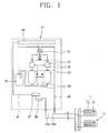
- FIG. 1 is a schematic view showing one embodiment of an air conditioner in accordance with the conventional art.
- the conventional air conditioner is divided into an indoor unit 11 and an outdoor unit 21, and the indoor unit 11 is composed of an indoor heat exchanger 13 for heat-exchanging a refrigerant indoors and an indoor expansion device 15 for depressurization-expanding a refrigerant.
- the outdoor unit 21 is composed of a compressor 23 for compressing refrigerant gas, an outdoor heat exchanger 33 for heat-exchanging a refrigerant with external air, a four-way valve 31 adjacently arranged to the compressor 23 for circulating a compression refrigerant discharged from the compressor 23 according to a heating cycle or a cooling cycle, an accumulator 35 arranged at an inlet of the compressor 23 for filtering a liquefied refrigerant, a first refrigerant path 41 for connecting the outdoor heat exchanger 33 to the indoor unit 11, and a second refrigerant path 42 for connecting the four-way valve 31 to the indoor unit 11.
- an oil separator 25 for separating oil, an oil returning path 29 for recycling oil separated by the oil separator 25 into the compressor 23, and a check valve 27 for preventing a backflow of a refrigerant are installed between an outlet of the compressor 23 and the four-way valve 31.
- a receiver 37 for temporarily receiving a refrigerant and a drier 39 for removing moisture are installed in the middle of the first refrigerant path 41, and service valves 45a and 45b are respectively installed at the first and second refrigerant paths 41 and 42.
- Both heating and cooling are operated in said conventional air conditioner.
- a refrigerant compressed in the compressor 23 is introduced into the outdoor heat exchanger 33 by the four-way valve 31, and the refrigerant which has passed through the outdoor heat exchanger 33 is introduced into the indoor expansion device 15 and the indoor heat exchanger 13 of the indoor unit 11 through the first refrigerant path 41.
- the refrigerant which has passed through the indoor unit 11 is introduced into the four-way valve 31 through the second refrigerant flow 42, and the refrigerant which has passed through the four-way valve 31 passes through the accumulator 35 thus to be introduced into the compressor 23. Accordingly, by said cooling cycle of a refrigerant, the cooling operation of the air conditioner is performed.
- the refrigerant compressed in the compressor 23 passes through the indoor expansion device 15 and the indoor heat exchanger 13 of the indoor unit 11 by the four-way valve 31 through the second refrigerant path 42, and the refrigerant discharged from the indoor unit 11 is introduced into the outdoor heat exchanger 33 through the firs refrigerant path 41.
- the refrigerant which has passed through the outdoor heat exchanger 33 passes through the four-way valve 31 and the accumulator 35 thus to be introduced into the compressor 23. Accordingly, by said heating cycle of a refrigerant, the heating operation of the air conditioner is performed.
- a defrosting cycle of a refrigerant for performing the defrosting operation is formed of a reverse cycle of the heating cycle like the cooling cycle.
- FIG. 2 is a schematic view showing another embodiment of the air conditioner in accordance with the conventional art.
- a plurality of outdoor units 21 having the same structure as the aforementioned embodiment are installed in parallel in order to enhance efficiency of the air conditioner in case that great cooling and heating capacity is required.
- each outdoor unit 21 is connected to main paths 48 and 47 for introducing and discharging a refrigerant into the indoor unit 11 thus to perform cooling and heating operations.
- a refrigerant which has performed the defrosting operation of the outdoor heat exchanger 33 passes through the indoor expansion device 15 and the indoor heat exchanger 13 of the indoor unit 11. Accordingly, when the defrosting operation is performed after stopping the heating operation, a refrigerant which circulates through the indoor expansion device 15 and the indoor heat exchanger 13 during the heating operation is at once reversely circulated thus to cause noise of the indoor unit 11.
- an object of the present invention is to provide an air conditioner capable of preventing noise generated indoors by preventing a refrigerant from being introduced into an indoor unit by constituting a defrosting cycle so that a refrigerant can circulate in an outdoor unit itself at the time of a defrosting operation of the outdoor unit, and an outdoor unit therefor.
- Another object of the present invention is to provide an air conditioner capable of consecutively performing a heating operation of an indoor unit and preventing an indoor heat loss by constructing each outdoor unit to separately perform defrosting and heating operations in case that a plurality of outdoor units are arranged by preventing a refrigerant from being introduced into the indoor unit by constructing a defrosting cycle so that the refrigerant can circulate in the outdoor unit itself at the time of defrosting operation of the outdoor unit, and an outdoor unit therefor.
- an air conditioner comprising an outdoor unit and an indoor unit provided with an indoor heat exchanger and an indoor expansion device, wherein the outdoor unit comprises a compressor for compressing a refrigerant; an outdoor heat exchanger for heat-exchanging a refrigerant; a four-way valve adjacently arranged to the compressor for circulating a refrigerant discharged from the compressor according to a heating cycle or a cooling cycle; and a refrigerant detouring path for detouring a refrigerant discharged from the outdoor heat exchanger to the compressor at the time of a defrosting operation.
- an outdoor unit for an air conditioner comprising a compressor; an outdoor heat exchanger for heat-exchanging a refrigerant with external air; a four-way valve adjacently arranged to the compressor, for changing a flow-path of a refrigerant for circulating a refrigerant according to a heating cycle or a cooling cycle; a first refrigerant path for connecting the outdoor heat exchanger to an indoor unit; a second refrigerant path for connecting the four-way valve to the indoor unit; a refrigerant detouring path connected to the first refrigerant path by a first three-way valve and connected to the second refrigerant path by a second three-way valve for detouring a refrigerant at the time of a defrosting cycle; an outdoor expansion device installed in the middle of the refrigerant detouring path for lowering a pressure of a refrigerant which flows in the
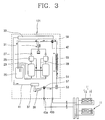
- FIG. 3 is a schematic view showing one embodiment of an air conditioner according to the present invention.
- the air conditioner is composed of a plurality of indoor units 11 constituted with an indoor heat exchanger 13 for heat-exchanging a refrigerant and an indoor expansion device 15 and arranged in parallel, and an outdoor unit 121.
- the outdoor unit 121 and the indoor units 11 are connected to each other by a connection pipe.
- the outdoor unit 121 comprises a compressor 23 for compressing refrigerant gas, an outdoor heat exchanger 33 for heat-exchanging a refrigerant with external air, a four-way valve 31 adjacently arranged to the compressor 23, for changing a flow-path of a refrigerant for circulating a refrigerant according to a heating cycle or a cooling cycle, an accumulator 35 arranged at an inlet of the compressor 23 for filtering a liquefied refrigerant, a first refrigerant path 41 for connecting the outdoor heat exchanger 33 to an indoor unit 11, a second refrigerant path 42 for connecting the four-way valve 31 to the indoor unit 11, a refrigerant detouring path 51 connected to the first refrigerant path 41 by a first three-way valve 57 and connected to the second refrigerant path 42 by a second three-way valve 59 for detouring a refrigerant at the time of a defrosting cycle, an outdoor expansion device 53 installed in the middle of the refrigerant detouring
- the heat exchanging unit 55 is formed of a heat conducting coil which winds the refrigerant detouring path 51, and the outdoor expansion device 53 is formed of an electron expansion valve.
- an oil separator 25 for separating oil contained in a refrigerant, an oil returning path 29 for recycling oil separated by the oil separator 25 into the compressor 23, and a check valve 27 for preventing a backflow of a refrigerant are installed between an outlet of the compressor 23 and the four-way valve 31.
- a receiver 37 for temporarily receiving a refrigerant and a drier 39 for removing moisture contained in a refrigerant are installed in the middle of the first refrigerant path 41, and service valves 45a and 45b are respectively connected to the first and second refrigerant paths 41 and 42.
- a refrigerant path is changed by controlling a valve position by the four-way valve 31, thereby performing a heating cycle and a cooling cycle. That is, at the time of the cooling cycle of the air conditioner, a refrigerant compressed in the compressor 23 passes through the four-way valve 31 thus to be introduced into the outdoor heat exchanger 33. Then, the refrigerant passes through the first refrigerant path 41 thus to pass through the indoor expansion device 15 and the indoor heat exchanger 13, and then passes through the four-way valve 31 and the accumulator 35 through the second refrigerant path 42 thus to be introduced into the compressor 23.
- the heating cycle of the air conditioner is performed as a reverse cycle of the cooling cycle. That is, the refrigerant compressed in the compressor 23 passes through the second refrigerant path 42 by an operation of the four-way valve 31, and the refrigerant discharged from the indoor unit 11 is introduced into the outdoor heat exchanger 33 through the first refrigerant path 41. Also, the refrigerant which has passed through the outdoor heat exchanger 33 passes through the four-way valve 31 and the accumulator 35 thus to be introduced into the compressor 23.
- a defrosting cycle for removing frost generated at the heat exchanger 33 is operated.
- the defrosting cycle is performed similarly to the cooling cycle, but a refrigerant which has passed through the outdoor heat exchanger is not introduced into the indoor unit through the first refrigerant path but passes through the refrigerant detouring path by the first and second three-way valves 57 and 59 thus to be introduced into the compressor 23.
- the refrigerant compressed in the compressor 23 passes through the four-way valve 31 thus to be introduced into the outdoor heat exchanger 33, and the refrigerant discharged from the outdoor heat exchanger 33 passes through the first refrigerant path 41 and the first three-way valve 57 thus to be introduced into the refrigerant detouring path 51.
- the refrigerant is not introduced into the indoor unit 11 by the first three-way valve 57.
- the refrigerant which has passed through the first three-way valve 57 passes through the outdoor expansion device 53 and the heat exchanging unit 55 and passes through the second three-way valve 59 thus to be introduced into the four-way valve 31.
- the refrigerant is not introduced into the second refrigerant path 42 by the second three-way valve 57. Also, the refrigerant which has been introduced into the four-way valve 31 passes through the accumulator 35 thus to be introduced into the compressor 23. In said defrosting cycle, the outdoor expansion device 53 and the heat exchanging unit 55 serve as the indoor heat exchanger 13 and the indoor expansion device 15 of the indoor unit 11.
- the refrigerant which has passed through the outdoor heat exchanger 33 is not introduced into the indoor unit 11, but passes through the refrigerant detouring path 51 thus to circulate in the compressor 23, thereby preventing noise generated from the indoor unit 11.
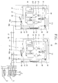
- An air conditioner according to another embodiment of the present invention is composed of a plurality of outdoor units 121 and 221 including a compressor 23 and an outdoor heat exchanger 33 and arranged in parallel, and a plurality of indoor units 11 including an indoor heat exchanger 13 and an indoor expansion device 15 and arranged in parallel.
- Each outdoor unit is connected to one another by main paths 48 and 47 for introducing and discharging a refrigerant to the indoor unit.
- Each outdoor unit 121 and 221 is similar to the aforementioned first embodiment structurally and operationally.
- the outdoor unit 121 for performing a heating cycle is illustrated on the right side of FIG. 4, and the outdoor unit 221 for performing a defrosting cycle is illustrated on the left side of FIG. 4.
- the defrosting operation for removing frost generated at the outdoor heat exchanger 33, a refrigerant is not leaked to outside of the outdoor units 121 and 221 but circulates in the outdoor units 121 and 221. Accordingly, even if the defrosting operation is performed at one outdoor unit of the plurality of outdoor units, the defrosting operation does not influence to other outdoor units or other indoor units, thereby continuing the heating operation of the air conditioner.
- the defrosting operation is performed in a state that the heating cycle is not stopped thus to prevent indoor heating loss.
Landscapes
- Engineering & Computer Science (AREA)
- Physics & Mathematics (AREA)
- Mechanical Engineering (AREA)
- Thermal Sciences (AREA)
- General Engineering & Computer Science (AREA)
- Air Conditioning Control Device (AREA)
- Compression-Type Refrigeration Machines With Reversible Cycles (AREA)
- Other Air-Conditioning Systems (AREA)
Abstract
Description
Claims (11)
- An air conditioner comprising an outdoor unit and an indoor unit provided with an indoor heat exchanger and an indoor expansion device, wherein the outdoor unit comprises:a compressor for compressing a refrigerant;an outdoor heat exchanger for heat-exchanging a refrigerant;a four-way valve adjacently arranged to the compressor for circulating a refrigerant discharged from the compressor according to a heating cycle or a cooling cycle; anda refrigerant detouring path for detouring a refrigerant discharged from the outdoor heat exchanger to the compressor at the time of a defrosting operation.
- The air conditioner of claim 1, wherein an outdoor expansion device for reducing a pressure of a refrigerant is installed in the middle of the detouring path.
- The air conditioner of claim 2, wherein the outdoor expansion device is an electron expansion valve.
- The air conditioner of claim 2, wherein a heat exchanging unit for heating a refrigerant is installed in the middle of the detouring path.
- The air conditioner of claim 4, wherein the heat exchanging unit is formed of a heat conducting coil which winds the refrigerant detouring path.
- The air conditioner of claim 1, wherein the refrigerant detouring path is connected to a first refrigerant path for connecting the outdoor heat exchanger and the indoor unit by a first three-way valve, and is connected to a second refrigerant path for connecting the four-way valve and the indoor unit by a second three-way valve.
- The air conditioner of claim 6, further comprising a receiver for temporarily receiving a refrigerant passing through the first refrigerant path; and
a drier installed between the first refrigerant path and the first three-way valve, for removing moisture of a refrigerant. - The air conditioner of claim 1, wherein a plurality of the outdoor unit are arranged in parallel.
- An outdoor unit for an air conditioner comprising:a compressor;an outdoor heat exchanger for heat-exchanging a refrigerant with external air;a four-way valve adjacently arranged to the compressor, for changing a flow-path of a refrigerant for circulating a refrigerant according to a heating cycle or a cooling cycle;a first refrigerant path for connecting the outdoor heat exchanger to an indoor unit;a second refrigerant path for connecting the four-way valve to the indoor unit;a refrigerant detouring path connected to the first refrigerant path by a first three-way valve and connected to the second refrigerant path by a second three-way valve for detouring a refrigerant at the time of a defrosting cycle;an outdoor expansion device installed in the middle of the refrigerant detouring path for lowering a pressure of a refrigerant which flows in the refrigerant detouring path; anda heat exchanging unit installed between the outdoor expansion device and the second three-way valve for heat-exchanging a refrigerant which has passed through the outdoor expansion device.
- The outdoor unit for an air conditioner of claim 9, wherein the heat exchanging unit is formed of a heat conducting coil which winds the refrigerant detouring path.
- The outdoor unit for an air conditioner of claim 9, further comprising an accumulator arranged between an outlet of the four-way valve and an inlet of the compressor for filtering a liquefied refrigerant.
Applications Claiming Priority (2)
| Application Number | Priority Date | Filing Date | Title |
|---|---|---|---|
| KR2003028044 | 2003-05-01 | ||
| KR10-2003-0028044A KR100511286B1 (en) | 2003-05-01 | 2003-05-01 | Air conditioner capable of defrosting and heating operation simultaneously and out door unit with self defrosting cycle for air conditioner |
Publications (3)
| Publication Number | Publication Date |
|---|---|
| EP1475585A2 true EP1475585A2 (en) | 2004-11-10 |
| EP1475585A3 EP1475585A3 (en) | 2005-09-07 |
| EP1475585B1 EP1475585B1 (en) | 2009-12-09 |
Family
ID=32985948
Family Applications (1)
| Application Number | Title | Priority Date | Filing Date |
|---|---|---|---|
| EP03292921A Expired - Lifetime EP1475585B1 (en) | 2003-05-01 | 2003-11-25 | Air conditioner |
Country Status (6)
| Country | Link |
|---|---|
| US (1) | US6851273B2 (en) |
| EP (1) | EP1475585B1 (en) |
| JP (1) | JP4444638B2 (en) |
| KR (1) | KR100511286B1 (en) |
| CN (1) | CN1256561C (en) |
| DE (1) | DE60330441D1 (en) |
Cited By (1)
| Publication number | Priority date | Publication date | Assignee | Title |
|---|---|---|---|---|
| EP2515053A3 (en) * | 2011-04-22 | 2017-05-31 | LG Electronics Inc. | Multi type air conditioner and operating method |
Families Citing this family (20)
| Publication number | Priority date | Publication date | Assignee | Title |
|---|---|---|---|---|
| CN100432580C (en) * | 2004-11-29 | 2008-11-12 | 乐金电子(天津)电器有限公司 | Compressor circulation system of one dragging more air conditioner |
| US7415838B2 (en) * | 2005-02-26 | 2008-08-26 | Lg Electronics Inc | Second-refrigerant pump driving type air conditioner |
| JP5258197B2 (en) * | 2007-01-16 | 2013-08-07 | 三菱電機株式会社 | Air conditioning system |
| KR101533112B1 (en) * | 2008-08-25 | 2015-07-02 | 엘지전자 주식회사 | Heat pump system and method for controlling the same |
| US9273875B2 (en) * | 2008-10-29 | 2016-03-01 | Mitsubishi Electric Corporation | Air conditioning apparatus having indoor, outdoor, and relay units |
| CN101571327B (en) * | 2009-06-05 | 2013-07-17 | 江苏春兰空调设备有限公司 | Control method of multi-connected heat pump air-conditioning unit parallelly connected by outdoor units |
| JP5581987B2 (en) * | 2010-11-15 | 2014-09-03 | ダイキン工業株式会社 | Air conditioner |
| CN102022854B (en) * | 2010-12-01 | 2012-07-04 | 山东大学 | Composite refrigerating and heat pump system |
| KR101324935B1 (en) * | 2011-10-11 | 2013-11-01 | 엘지전자 주식회사 | Air conditioner |
| CN103363626A (en) * | 2012-03-31 | 2013-10-23 | 青岛海信日立空调系统有限公司 | Air conditioner circulation system |
| CN103673438B (en) * | 2012-09-20 | 2015-11-25 | 广东美的暖通设备有限公司 | A kind of sustainable multi-connected air conditioner of heating and Defrost method thereof |
| CN103791569B (en) * | 2012-10-30 | 2016-10-05 | 珠海格力电器股份有限公司 | Heat pump type air conditioning system |
| CN104236155B (en) * | 2013-06-20 | 2016-12-28 | 青岛海尔空调电子有限公司 | Have that coolant is supercool, the defrosting air conditioning system of heat-production functions and control method thereof |
| CN106524389B (en) * | 2015-09-15 | 2020-11-10 | 上海海立电器有限公司 | A kind of air conditioner defrosting method and air conditioner thereof |
| CN105423589B (en) * | 2015-11-20 | 2019-04-02 | Tcl空调器(中山)有限公司 | Air conditioner and control method thereof |
| CN105605841A (en) * | 2016-02-02 | 2016-05-25 | 广东美的制冷设备有限公司 | Air conditioning system and defrosting control method thereof |
| CN105698450A (en) * | 2016-02-02 | 2016-06-22 | 广东美的制冷设备有限公司 | Air conditioner system and defrosting control method of air conditioner system |
| CN111902681B (en) * | 2018-04-09 | 2022-02-18 | 三菱电机株式会社 | Air conditioner |
| JP6965462B2 (en) | 2018-12-11 | 2021-11-10 | 三菱電機株式会社 | Air conditioner |
| CN113007865B (en) * | 2021-04-20 | 2022-09-20 | 广东积微科技有限公司 | Multi-outdoor-unit parallel non-reversing defrosting system and defrosting control method thereof |
Family Cites Families (20)
| Publication number | Priority date | Publication date | Assignee | Title |
|---|---|---|---|---|
| US3604A (en) * | 1844-05-30 | samuel g | ||
| US4644756A (en) * | 1983-12-21 | 1987-02-24 | Daikin Industries, Ltd. | Multi-room type air conditioner |
| JPH07111288B2 (en) * | 1985-09-20 | 1995-11-29 | 株式会社日立製作所 | Air conditioner |
| US4646537A (en) * | 1985-10-31 | 1987-03-03 | American Standard Inc. | Hot water heating and defrost in a heat pump circuit |
| JPH0799297B2 (en) * | 1986-06-25 | 1995-10-25 | 株式会社日立製作所 | Air conditioner |
| JPH079331B2 (en) * | 1986-12-26 | 1995-02-01 | 松下電器産業株式会社 | Operation control method for heat pump type air conditioner |
| US5056327A (en) * | 1990-02-26 | 1991-10-15 | Heatcraft, Inc. | Hot gas defrost refrigeration system |
| JPH04110574A (en) * | 1990-08-30 | 1992-04-13 | Union Kogyo Kk | Method and apparatus for heating and cooling with refrigerant gas |
| US5105629A (en) * | 1991-02-28 | 1992-04-21 | Parris Jesse W | Heat pump system |
| WO1996000872A1 (en) * | 1994-06-29 | 1996-01-11 | Daikin Industries, Ltd. | Oil balancing operation control device for an air conditioner |
| JP3287260B2 (en) * | 1997-04-07 | 2002-06-04 | ダイキン工業株式会社 | Refrigeration apparatus and refrigerant charging method thereof |
| JPH11108507A (en) * | 1997-10-03 | 1999-04-23 | Hitachi Ltd | Air conditioner |
| US5983660A (en) * | 1998-01-15 | 1999-11-16 | Geofurnace Systems, Inc. | Defrost subcircuit for air-to-air heat pump |
| US6244057B1 (en) * | 1998-09-08 | 2001-06-12 | Hitachi, Ltd. | Air conditioner |
| JP4056151B2 (en) * | 1998-11-16 | 2008-03-05 | カルソニックカンセイ株式会社 | Heat pump air conditioner |
| JP2000274838A (en) * | 1999-03-25 | 2000-10-06 | Tgk Co Ltd | Refrigeration cycle with bypass line |
| JP2001253227A (en) * | 2000-03-14 | 2001-09-18 | Zexel Valeo Climate Control Corp | Vehicle air conditioner |
| JP2002195677A (en) * | 2000-10-20 | 2002-07-10 | Denso Corp | Heat pump cycle |
| US6666043B2 (en) * | 2002-05-07 | 2003-12-23 | Lg Electronics, Inc. | Dewfall preventing device of refrigerator |
| KR100484802B1 (en) | 2002-07-03 | 2005-04-22 | 엘지전자 주식회사 | Frost removing method of air conditioner hanving two compressor |
-
2003
- 2003-05-01 KR KR10-2003-0028044A patent/KR100511286B1/en not_active Expired - Fee Related
- 2003-11-25 EP EP03292921A patent/EP1475585B1/en not_active Expired - Lifetime
- 2003-11-25 DE DE60330441T patent/DE60330441D1/en not_active Expired - Lifetime
- 2003-11-25 US US10/720,114 patent/US6851273B2/en not_active Expired - Lifetime
- 2003-12-05 JP JP2003406836A patent/JP4444638B2/en not_active Expired - Fee Related
- 2003-12-29 CN CNB2003101242851A patent/CN1256561C/en not_active Expired - Fee Related
Cited By (1)
| Publication number | Priority date | Publication date | Assignee | Title |
|---|---|---|---|---|
| EP2515053A3 (en) * | 2011-04-22 | 2017-05-31 | LG Electronics Inc. | Multi type air conditioner and operating method |
Also Published As
| Publication number | Publication date |
|---|---|
| JP2004333107A (en) | 2004-11-25 |
| EP1475585A3 (en) | 2005-09-07 |
| KR100511286B1 (en) | 2005-08-31 |
| EP1475585B1 (en) | 2009-12-09 |
| US20040216480A1 (en) | 2004-11-04 |
| CN1256561C (en) | 2006-05-17 |
| DE60330441D1 (en) | 2010-01-21 |
| JP4444638B2 (en) | 2010-03-31 |
| KR20040094099A (en) | 2004-11-09 |
| CN1542390A (en) | 2004-11-03 |
| US6851273B2 (en) | 2005-02-08 |
Similar Documents
| Publication | Publication Date | Title |
|---|---|---|
| US6851273B2 (en) | Air conditioner and outdoor unit therefor | |
| US7407002B2 (en) | Air conditioner and outdoor unit therefor | |
| US5673570A (en) | Oil equalizing operation control device for air conditioner | |
| US9587867B2 (en) | Chiller system and control method thereof | |
| US7204094B2 (en) | Air conditioner | |
| US5685168A (en) | Refrigerating apparatus | |
| EP1703230A2 (en) | Multi type air-conditioner and control method thereof | |
| JPWO1996000872A1 (en) | Oil-equalizing operation control device for air conditioning equipment | |
| US9267720B2 (en) | Air conditioner and method of controlling the same | |
| US20170108250A1 (en) | Air conditioner | |
| EP2568232A2 (en) | Air conditioner | |
| US20190257554A1 (en) | Air conditioner | |
| US7464563B2 (en) | Air-conditioner having a dual-refrigerant cycle | |
| JP2010048506A (en) | Multi-air conditioner | |
| KR20180093570A (en) | Air conditioner | |
| KR102080836B1 (en) | An air conditioning system | |
| JP2001056156A (en) | Air conditioner | |
| KR100524719B1 (en) | By-pass device with variable flow rate of multi air-conditioner system | |
| KR20040089376A (en) | Controlling method of air conditioner using plural compressor | |
| EP4033175B1 (en) | Air conditioner | |
| CN110234938B (en) | Outdoor system of air conditioner | |
| JP2007046896A (en) | Operation control device and method for air conditioner provided with a plurality of compressors | |
| KR100496553B1 (en) | Control Method of Multi-Compressor for Air- Conditioner | |
| JP2010190541A (en) | Air conditioning device | |
| KR100632022B1 (en) | Control method of constant speed compressor of multi air conditioner |
Legal Events
| Date | Code | Title | Description |
|---|---|---|---|
| PUAI | Public reference made under article 153(3) epc to a published international application that has entered the european phase |
Free format text: ORIGINAL CODE: 0009012 |
|
| 17P | Request for examination filed |
Effective date: 20031202 |
|
| AK | Designated contracting states |
Kind code of ref document: A2 Designated state(s): AT BE BG CH CY CZ DE DK EE ES FI FR GB GR HU IE IT LI LU MC NL PT RO SE SI SK TR |
|
| AX | Request for extension of the european patent |
Extension state: AL LT LV MK |
|
| PUAL | Search report despatched |
Free format text: ORIGINAL CODE: 0009013 |
|
| AK | Designated contracting states |
Kind code of ref document: A3 Designated state(s): AT BE BG CH CY CZ DE DK EE ES FI FR GB GR HU IE IT LI LU MC NL PT RO SE SI SK TR |
|
| AX | Request for extension of the european patent |
Extension state: AL LT LV MK |
|
| AKX | Designation fees paid |
Designated state(s): DE FR GB IT |
|
| 17Q | First examination report despatched |
Effective date: 20061215 |
|
| GRAP | Despatch of communication of intention to grant a patent |
Free format text: ORIGINAL CODE: EPIDOSNIGR1 |
|
| RTI1 | Title (correction) |
Free format text: AIR CONDITIONER |
|
| GRAS | Grant fee paid |
Free format text: ORIGINAL CODE: EPIDOSNIGR3 |
|
| GRAA | (expected) grant |
Free format text: ORIGINAL CODE: 0009210 |
|
| AK | Designated contracting states |
Kind code of ref document: B1 Designated state(s): DE FR GB IT |
|
| REG | Reference to a national code |
Ref country code: GB Ref legal event code: FG4D |
|
| REF | Corresponds to: |
Ref document number: 60330441 Country of ref document: DE Date of ref document: 20100121 Kind code of ref document: P |
|
| PLBE | No opposition filed within time limit |
Free format text: ORIGINAL CODE: 0009261 |
|
| STAA | Information on the status of an ep patent application or granted ep patent |
Free format text: STATUS: NO OPPOSITION FILED WITHIN TIME LIMIT |
|
| 26N | No opposition filed |
Effective date: 20100910 |
|
| GBPC | Gb: european patent ceased through non-payment of renewal fee |
Effective date: 20101125 |
|
| PG25 | Lapsed in a contracting state [announced via postgrant information from national office to epo] |
Ref country code: GB Free format text: LAPSE BECAUSE OF NON-PAYMENT OF DUE FEES Effective date: 20101125 |
|
| REG | Reference to a national code |
Ref country code: FR Ref legal event code: PLFP Year of fee payment: 13 |
|
| REG | Reference to a national code |
Ref country code: FR Ref legal event code: PLFP Year of fee payment: 14 |
|
| REG | Reference to a national code |
Ref country code: FR Ref legal event code: PLFP Year of fee payment: 15 |
|
| PGFP | Annual fee paid to national office [announced via postgrant information from national office to epo] |
Ref country code: FR Payment date: 20171011 Year of fee payment: 15 |
|
| PGFP | Annual fee paid to national office [announced via postgrant information from national office to epo] |
Ref country code: IT Payment date: 20171115 Year of fee payment: 15 |
|
| PG25 | Lapsed in a contracting state [announced via postgrant information from national office to epo] |
Ref country code: IT Free format text: LAPSE BECAUSE OF NON-PAYMENT OF DUE FEES Effective date: 20181125 Ref country code: FR Free format text: LAPSE BECAUSE OF NON-PAYMENT OF DUE FEES Effective date: 20181130 |
|
| PGFP | Annual fee paid to national office [announced via postgrant information from national office to epo] |
Ref country code: DE Payment date: 20191004 Year of fee payment: 17 |
|
| REG | Reference to a national code |
Ref country code: DE Ref legal event code: R119 Ref document number: 60330441 Country of ref document: DE |
|
| PG25 | Lapsed in a contracting state [announced via postgrant information from national office to epo] |
Ref country code: DE Free format text: LAPSE BECAUSE OF NON-PAYMENT OF DUE FEES Effective date: 20210601 |