EP1475533A2 - Diaphragm carburetor with air purge system - Google Patents
Diaphragm carburetor with air purge system Download PDFInfo
- Publication number
- EP1475533A2 EP1475533A2 EP04005432A EP04005432A EP1475533A2 EP 1475533 A2 EP1475533 A2 EP 1475533A2 EP 04005432 A EP04005432 A EP 04005432A EP 04005432 A EP04005432 A EP 04005432A EP 1475533 A2 EP1475533 A2 EP 1475533A2
- Authority
- EP
- European Patent Office
- Prior art keywords
- fuel
- engine
- inlet
- carburetor
- recited
- Prior art date
- Legal status (The legal status is an assumption and is not a legal conclusion. Google has not performed a legal analysis and makes no representation as to the accuracy of the status listed.)
- Withdrawn
Links
Images


Classifications
-
- F—MECHANICAL ENGINEERING; LIGHTING; HEATING; WEAPONS; BLASTING
- F02—COMBUSTION ENGINES; HOT-GAS OR COMBUSTION-PRODUCT ENGINE PLANTS
- F02M—SUPPLYING COMBUSTION ENGINES IN GENERAL WITH COMBUSTIBLE MIXTURES OR CONSTITUENTS THEREOF
- F02M17/00—Carburettors having pertinent characteristics not provided for in, or of interest apart from, the apparatus of preceding main groups F02M1/00 - F02M15/00
- F02M17/02—Floatless carburettors
- F02M17/04—Floatless carburettors having fuel inlet valve controlled by diaphragm
Definitions
- the invention relates to fueling systems and, more particularly, relates to a fueling system utilizing a diaphragm carburetor to form an air/fuel mixture and to supply the mixture to an engine.
- the invention additionally relates to an engine fueled with such a system and a method of its use.
- Diaphragm carburetors are widely used to supply fuel to relatively small two-stroke and four-stroke utility engines.
- a diaphragm carburetor has a diaphragm chamber which opens to main jet and idling jet orifices. Fuel flow through the carburetor is controlled by a regulator located in the diaphragm chamber. The regulator continually opens and closes an inlet needle in response to the vacuum created in the carburetor's venturi. Fuel is supplied to the inlet needle via either a diaphragm pump or by gravity. In the case of the diaphragm pump, suction pulses of the engine are used force fuel through the pump and a series of check valves. The resultant volume of pressurized trapped fuel then flows from the regulator chamber to the fuel jet orifices at a rate that depends on the velocity of the air flow through the venturi which depends on the setting of the throttle valve and the speed of the engine.
- diaphragm carburetors do not have to be vented, and do not rely on the position of a float to maintain a desired volume of fuel in the carburetor. Fuel therefore cannot leak out of the carburetor, even if the carburetor is used on a machine that is subject to severe vibrations and/or that is often operated while inverted or lying on its side. Machines of this type include weed trimmers, chain saws, snow blowers, rammers, and breakers.
- a relative disadvantage of diaphragm carburetors is that engines fueled by them can be difficult to start, particularly when the engine has run out of fuel. This is because air can be trapped in the carburetor passage upstream of the diaphragm and in the fuel supply tube leading from the fuel tank to the carburetor. This air must be purged and the diaphragm chamber filled with fuel before the engine can start and run. Depending on the length and diameter of the fuel supply tube, this purging requirement can necessitate 15-20 starting pull cord strokes to purge all of the trapped air. This can be very fatiguing to operators.
- Prime bulb is a cap or bulb mounted on or adjacent to the engine and manually activated by an operator to draw fuel into the carburetor and purge air from it.
- Prime bulbs can be very effective, but they require manual operation apart from the usual starting operation. Operation of a prime bulb may result in the injection of fuel into the throat of the carburetor.
- activation of a prime bulb when the engine is warm, or when the engine fails to start on the first attempt, can flood the engine so that the engine will not start.
- prime bulbs usually are made of rubber or another resilient material that may become brittle with age and with contact with fuel. They therefore have a limited life. This life is further limited by the imposition of shocks and vibrations on the engine during operation of some implements, such as rammers and breakers.
- Closed choke Another technique that is sometimes employed to improve the cold startability of a diaphragm carburetor-equipped engine is a so-called "closed choke,” which is capable of completely or nearly completely closing a choke plate to minimize airflow through the carburetor during a starting operation so as to maximize the richness of the air/fuel mixture.
- An engine equipped with a closed choke cannot run with the choke fully closed. Instead, the operator must operate the pull cord with the choke closed until he or she detects what is known as a ''false hit" in which the engine begins to run but then dies. The operator must then partially or fully open the choke and pull the cord again to start the engine. Closed chokes require even more complex operator interaction than is required for actuation of a prime bulb. They also increase the risk of engine flooding.
- the need identified above is satisfied by providing a fuel system with a vented diaphragm carburetor.
- the engine's fuel supply passage opens into a vent passage that is configured to vent trapped vapor from the fuel supply passage.
- the fuel supply passage supplies fuel to the diaphragm chamber from the fuel tank. It typically comprises 1) a fuel supply tube that supplies fuel to the fuel inlet of the carburetor from the fuel tank and 2) internal passage(s) supplying fuel to the diaphragm chamber from the fuel inlet of the carburetor.
- the vent passage preferably comprises a vent tube having an inlet that opens into the fuel supply passage and having an outlet configured to open into an upper portion of the fuel tank.
- the vent tube inlet preferably opens into either an internal passage in the carburetor or a downstream portion of the fuel supply tube.
- the vent passage reduces the number of pull cord actuating strokes required to start a typical two-stroke or four-stroke engine after the engine has run out of fuel and has been refueled. This reduction is from at about 15 pull cord strokes to no more than 5, and even to 3 or less if the vent tube opens into an internal passage of the carburetor. It also can improve steady state operation of the engine by purging fuel vapor from a hot carburetor.
- the inventive air purge system permits the use of a choke plate that is incapable of being fully closed.
- the choke plate comprises a butterfly valve
- the butterfly valve may have at least one aperture formed therethrough through which air passes when the butterfly valve is fully closed.
- the air purge system may also reduce or avoid vapor lock by venting vaporized fuel from the fuel supply passage during engine operation.
- the inventive air purge system is usable with virtually any diaphragm carburetor-equipped two-stroke or four-stroke engine. Applications for these engines are also myriad. Hence, while a preferred embodiment of the inventive air purge system will now be described in conjunction with a reciprocating impact tool powered by such an engine, an engine, specifically a rammer, it is to be understood that it is usable with a variety of other powered devices as well.
- a rammer (sometimes known as a tamper) 20 is illustrated that includes an engine 22 and a rammer subassembly 24 bolted to one another to form an integral unit.
- the rammer subassembly 24 includes a rammer crankcase 26 and a reciprocating tamping shoe 28 connected to the rammer crankcase 26 by a reciprocating piston (not shown) so as to oscillate or reciprocate vertically upon rammer operation.
- the piston is protected at its lower end by a fixed guard 30 and at its upper end by a flexible boot 32 that accommodates movement of the shoe 28 relative to the rammer crankcase 26.
- the machine is supported and guided by an operator's handle 34 that also serves as a guard.
- the engine 22 is a spark ignited, single-cylinder, internal combustion engine. It may comprise either a two-stroke engine or a four-stroke engine.
- the cylinder (not shown) is encased in a crankcase 38 bolted to a rear surface of the rammer crankcase 26.
- the engine 22 is started via a pull-cord 42 mounted on the rear surface of the engine crankcase 38.
- the engine 22 is supplied with spark via a spark plug 44 and with fuel via a fuel supply system 46.
- the engine is not equipped with a prime bulb, although one could be provided, if desired.
- the fuel supply system 46 instead is equipped with an air purge system 48 constructed in accordance with a preferred embodiment of the present invention.
- the fuel supply system 46, and especially its air purge system 48, will now be described in greater detail.
- the fuel supply system 46 comprises an air purge system 48, a fuel tank 50, a carburetor 52, and a fuel supply line 54.
- the fuel tank 50 is mounted on the frame/handle 34 above the engine crankcase 38. It includes an upper fill port 56, a lower outlet 58, and a hollow interior configured to be filled with fuel to a maximum fill line 60 spaced from the top of the tank 50.
- the fuel supply line 54 comprises a flexible tube having an inlet connected to the lower outlet 58 of the fuel tank 50 by a first fitting 62 and an outlet coupled to a fuel inlet 68 of the carburetor 52 by a second fitting 64.
- the carburetor 52 includes a generally rectangular body 66 having the fuel inlet 68, an air inlet 70, and a mixture outlet 74 (Figs. 6 and 7) which typically takes the form of one or more jets.
- Airflow into the carburetor 52 is controlled by a throttle 76 that is actuated by a throttle cable 78 in a manner which is, per se, well-known.
- the air inlet 70 can be selectively partially closed by a choke plate.
- the choke plate takes the form of a butterfly valve 80 operated by a manual choke lever 82. Pursuant to the invention, however, the butterfly valve 80 is not fully closable for reasons detailed below.
- Air and fuel are drawn through the carburetor 52 from the respective inlets 70 and 64, mixed with one another, and discharged from the outlet 74 under operation of an internal diaphragm pump 84 (Figs. 6 and 7) located in a diaphragm chamber (not shown).
- the carburetor 52 as thus far described may be of a type commercially available from various manufacturers such as Walbro Corporation of Cass City, Michigan or Tillotson, Ltd. of Ireland.
- the illustrated carburetor 52 is a Tillotson carburetor modified only 1) so that its choke is not fully closable and 2) to mate with the air purge system 48.
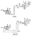
- the air purge system 48 comprises a vent passage and related couplings that vent fuel from a downstream portion of the fuel passage (formed by the fuel line 54 and the internal passages of the carburetor 52 leading from the fuel inlet 68 to the diaphragm chamber) to a location remote from that portion.
- the vent passage takes the form of a simple flexible vent tube 90 having an inlet 92 and an outlet 94.
- the vent tube outlet 94 is disposed so as to safely direct vented air, which may be heavy laden with vaporized fuel, to a remote location, preferably the interior of the fuel tank 50.
- the vent tube outlet 94 preferably opens into the fuel tank 50 at a location above the maximum fill line 60. This effect is achieved most conveniently by running the vent tube 90 up into the fuel tank 50 from a lower vent tube inlet port 95.
- the vent tube inlet 92 is preferably located as close as practical to the diaphragm chamber of the carburetor 52. In the embodiment illustrated in Figs. 1-6, this effect is obtained by connecting the vent tube inlet 92 to an internal fuel passage in the carburetor 52.
- the carburetor body 66 incorporates a vent port 72 that opens into an internal fuel passage of the carburetor 52.
- a convenient location for vent port 72 is one in which it opens into an auxiliary diaphragm chamber 96 located on the side of the carburetor body 66.
- chamber 96 can be accessed by removing a cover 98 from the side of the carburetor body 66.
- the thus-exposed chamber 96 is bounded at one side by a recess in the carburetor body 66 and at another side by a facing recess in the cover 98.
- the chamber 96 has a fuel inlet 100 connected to the fuel inlet port 68 of the carburetor 52 via a first internal passage 102 in the body 66 and an outlet 104 at least indirectly connected to the diaphragm chamber 96 via a second internal passage 106 in the body 66.
- the outer portion of the chamber 96 typically is separated from the inner portion containing the fuel inlet 100 and fuel outlet 104 by a diaphragm (seen in phantom at 108).
- diaphragm 108 can be removed to provide unrestricted airflow from the inner portion of that chamber 96 to the outer portion thereof when the vent port 72 is drilled into the outer portion of chamber 96 by drilling a hole through the cover 98.
- vent tube inlet 92 can be coupled to the vent port 72 by a suitable fitting 110. Air is now free to flow to the fuel tank 50 from the chamber 96 and all upstream portions of the fuel supply passage via the vent port 72 and the vent tube 90.
- vent tube inlet 92 may be coupled to another location in the fuel supply passage. That location should preferably be in the fuel supply tube as close as practical to the carburetor fuel inlet port, such as in the fuel inlet fitting coupling the fuel supply tube to the fuel inlet of the carburetor.
- An air purge system 148 configured in this manner is illustrated schematically in Fig. 7, in conjunction with the same fuel supply system 46 of Figs. 1-6.
- the fitting 164 connecting the fuel supply tube 54 to the carburetor fuel inlet port 68 takes the form of a T-fitting having a fuel inlet coupled to the outlet of the fuel supply tube 54, a fuel outlet opening to the fuel inlet port 68 of the carburetor 52, and an air outlet coupled to the inlet 92 of the vent tube.
- Fig. 7 is slightly less effective at improving startability, but still dramatically reduces the number of pulls required to start the engine. It is estimated that the system of Fig. 7 requires no more than 5 to 6 pull strokes to start a freshly fueled engine - still a dramatic improvement over the 15 to 17 that might otherwise be required.
- diaphragm carburetors typically employ a choke plate that must be closed fully prior to engine starting to maximize the richness of the fuel charge during a cold start operation.
- an engine equipped with this type of carburetor cannot run and remain idling with the choke is fully closed but, instead, is subject to a ''false hit" in which the engine runs a few revolutions on its own and then dies. The operator must then partially open or ''back off" the choke prior to once again attempting to start the engine.
- the inventive air purge system is so effective at obtaining rapid fuel delivery to the carburetor that it is unnecessary to fully close the choke to start a cold engine.
- the choke plate can be configured to lack the ability to fully close but, instead, to have a minimum airflow passage that it is a relatively small percentage of the maximum airflow passage.
- the airflow passage available upon choke plate closure is typically on the order of 5 % of the maximum area of the airflow passage. This effect could be achieved, for instance, by providing a stop in the vicinity of the choke plate seat and/or adjacent the choke lever to prevent full choke plate closure.
- the choke plate comprises a butterfly valve 80
- this effect can be achieved simply by drilling one or more apertures 120 in the butterfly valve 80 having a combined area on the order of at least 4%, and preferably about 5 % of the total area of the butterfly valve 80.
- the thus equipped choke allows sufficient airflow through the carburetor 52 to allow the engine to start and run at idle, even when the choke is fully set. The need to obtain a false hit and then open the choke prior to starting the engine therefore is negated.
- Still another benefit of the inventive vapor air purge system is that it may prevent vapor lock by venting vaporized fuel from a hot carburetor and thereby preventing the vaporized fuel from backing up into the fuel line.
Landscapes
- Engineering & Computer Science (AREA)
- Chemical & Material Sciences (AREA)
- Combustion & Propulsion (AREA)
- Mechanical Engineering (AREA)
- General Engineering & Computer Science (AREA)
- Means For Warming Up And Starting Carburetors (AREA)
Abstract
Description
Claims (31)
- A fuel system comprising:(A) a diaphragm carburetor having a fuel inlet, an air inlet, an air/fuel mixture outlet, and a diaphragm chamber;(B) a fuel supply passage configured to direct fuel from a fuel outlet of a fuel tank, through said fuel inlet of said carburetor, and to said diaphragm chamber of said carburetor; and(C) a vent passage that is configured to vent trapped vapor from said fuel supply passage.
- The fuel system as recited in claim 1, wherein said vent passage comprises a vent tube having an inlet and having an outlet configured to open into an upper portion of the fuel tank.
- The fuel system as recited in claim 2, wherein said carburetor has an internal fuel supply passage leading from said fuel inlet to said diaphragm chamber and forming a portion of said fuel supply passage, and wherein said inlet of said vent tube opens into said internal fuel supply passage.
- The fuel system as recited in claim 2, wherein said fuel supply passage comprises a fuel supply tube having an outlet coupled to said fuel inlet of said carburetor, and wherein said inlet of said vent tube opens into said fuel supply tube adjacent the outlet thereof.
- The fuel system as recited in claim 1, wherein said carburetor includes a choke plate that is incapable of being fully closed.
- The fuel system as recited in claim 5, wherein said choke plate comprises a butterfly valve having at least one aperture formed therethrough through which air passes when the butterfly valve is fully closed.
- The fuel system as recited in claim 6, wherein at least 4% of a surface area of the butterfly valve is apertured.
- An internal combustion engine fueled by the fuel system of claim 1.
- The internal combustion engine as recited in claim 8, wherein the engine is a two-stroke engine.
- The internal combustion engine as recited in claim 8, wherein the engine is a four-stroke engine.
- A ground working appliance powered by the internal combustion engine of claim 8.
- An internal combustion engine comprising:(A) a cylinder;(B) a diaphragm carburetor having a fuel inlet, an air inlet, an air/fuel mixture outlet configured to supply an air/fuel mixture to said cylinder, and an internal diaphragm chamber located between said fuel inlet and said air/fuel mixture outlet;(C) a fuel tank having a fuel outlet, a fuel inlet, and a maximum fill line located above said fuel outlet thereof;(D) a fuel supply tube having an inlet in fluid communication with said fuel outlet of said fuel tank and an outlet in fluid communication with said fuel inlet of said carburetor, and(E) a vent tube having an inlet and an outlet, said inlet being located between said inlet of said fuel supply tube and said diaphragm chamber in said carburetor, said outlet opening into said fuel tank at a location above said maximum fill line.
- The engine as recited in claim 12, wherein said carburetor has an internal fuel supply passage leading from said fuel inlet to said diaphragm chamber, and wherein said inlet of said vent tube opens into said internal fuel supply passage.
- The engine as recited in claim 13, wherein said inlet of said vent tube opens into said fuel supply tube adjacent the outlet thereof.
- The engine as recited in claim 12, wherein said carburetor includes a choke plate that is incapable of being fully closed.
- The engine as recited in claim 15, wherein said choke plate comprises a butterfly valve having at least one aperture formed therethrough through which air passes when said butterfly valve is fully-closed.
- The engine as recited in claim 16, wherein at least 4% of a surface area of said butterfly valve is apertured.
- The engine as recited in claim 12, wherein the engine is a two-stroke engine.
- The engine as recited in claim 12, wherein the engine is a four-stroke engine.
- A method comprising:(A) filling an empty fuel tank of an engine;(B) automatically purging essentially all air in a fuel supply passage leading from an outlet of said fuel tank to a diaphragm chamber of a diaphragm carburetor of said engine; and then(C) cranking said engine to start said engine.
- The method as recited in claim 20, wherein the purging step comprises permitting air to flow out of said fuel supply passage through a vent tube having an inlet opening into said fuel supply passage at a location in or near said carburetor.
- The method as recited in claim 21, wherein the purging step comprises directing the air through the vent tube and into said fuel tank.
- The method as recited in claim 21, wherein the vent tube inlet opens into an internal passage in said carburetor.
- The method as recited in claim 21, wherein the vent tube inlet opens into a fuel supply tube at a location adjacent a fuel supply inlet of said carburetor.
- The method as recited in claim 20, wherein the cranking step comprises imposing a number N of manually imposed starting strokes without priming said engine, wherein N is no more than 10.
- The method as recited in claim 25, wherein N is no more than 5.
- The method as recited in claim 25, wherein N is no more than 3.
- The method as recited in claim 25, wherein the imposing step comprises pulling a pull cord once during each starting stroke.
- The method as recited in claim 20, further comprising setting a choke prior to the cranking step, and wherein the engine starts and runs without releasing said choke.
- A method comprising:(A) pouring fuel into an empty fuel tank of an engine supplied with an air/fuel mixture by a diaphragm carburetor; then(B) without priming said engine, starting said engine by cranking said engine through a number N of manually imposed starting strokes, N being less than 10.
- The method as recited in claim 30, wherein N is no more than 5.
Applications Claiming Priority (2)
| Application Number | Priority Date | Filing Date | Title |
|---|---|---|---|
| US430706 | 2003-05-06 | ||
| US10/430,706 US6874482B2 (en) | 2003-05-06 | 2003-05-06 | Diaphragm carburetor with air purge system |
Publications (2)
| Publication Number | Publication Date |
|---|---|
| EP1475533A2 true EP1475533A2 (en) | 2004-11-10 |
| EP1475533A3 EP1475533A3 (en) | 2007-04-11 |
Family
ID=32990520
Family Applications (1)
| Application Number | Title | Priority Date | Filing Date |
|---|---|---|---|
| EP04005432A Withdrawn EP1475533A3 (en) | 2003-05-06 | 2004-03-08 | Diaphragm carburetor with air purge system |
Country Status (4)
| Country | Link |
|---|---|
| US (1) | US6874482B2 (en) |
| EP (1) | EP1475533A3 (en) |
| JP (1) | JP2004332720A (en) |
| CN (1) | CN1550656A (en) |
Families Citing this family (7)
| Publication number | Priority date | Publication date | Assignee | Title |
|---|---|---|---|---|
| US7334551B2 (en) * | 2004-09-27 | 2008-02-26 | Walbro Engine Management, L.L.C. | Combustion engine pull cord start system |
| DE102005061604B4 (en) * | 2005-12-22 | 2013-09-19 | Webasto Ag | Fuel extraction system for an auxiliary heater, auxiliary heater and motor vehicle with such a fuel extraction system |
| SE529616C2 (en) | 2006-02-17 | 2007-10-09 | Dynapac Compaction Equip Ab | Fuel |
| JP2009047088A (en) * | 2007-08-21 | 2009-03-05 | Yamaha Marine Co Ltd | Fuel supply device for engine |
| MX2010002091A (en) * | 2007-09-04 | 2010-05-03 | Kohler Co | Externally vented carburetor system with vapor containment. |
| US8146569B2 (en) * | 2009-05-12 | 2012-04-03 | GM Global Technology Operations LLC | Control systems and methods for newly assembled engines |
| DE102018212640A1 (en) * | 2018-07-30 | 2020-01-30 | Bayerische Motoren Werke Aktiengesellschaft | Device and method for removing fuel vapor from a fuel supply system for an internal combustion engine |
Family Cites Families (25)
| Publication number | Priority date | Publication date | Assignee | Title |
|---|---|---|---|---|
| DE1808632B2 (en) * | 1968-11-13 | 1976-03-11 | Daimler-Benz Ag, 7000 Stuttgart | INLET CHANNEL OF A ROTATIONAL PISTON INJECTION ENGINE |
| US3789819A (en) | 1972-01-28 | 1974-02-05 | Gen Motors Corp | Fuel rail vapor bleed |
| JPS521231A (en) | 1975-06-23 | 1977-01-07 | Nissan Motor Co Ltd | Fuel injection device equipped with air evacuator |
| US4356801A (en) * | 1981-02-02 | 1982-11-02 | Chrysler Corporation | Throttle body fuel injection |
| JPS61159648U (en) | 1985-03-26 | 1986-10-03 | ||
| US4684485A (en) | 1986-08-26 | 1987-08-04 | Tillotson, Ltd. | Carburetor fuel primer |
| US4732131A (en) | 1986-08-26 | 1988-03-22 | Brunswick Corporation | Fuel line purging device |
| US4836157A (en) | 1987-11-09 | 1989-06-06 | Walbro Corporation | Cold-start engine priming and air purging system |
| US4905641A (en) | 1987-11-09 | 1990-03-06 | Walbro Corporation | Cold-start engine priming and air purging system |
| JPH01147147A (en) * | 1987-12-01 | 1989-06-08 | Walbro Far East Inc | Starting fuel feeder of internal combustion engine for portable farm working machine |
| FR2638785B1 (en) * | 1988-11-07 | 1991-01-25 | Solex | FUEL SUPPLY DEVICE FOR INTERNAL COMBUSTION ENGINE |
| DE4020947A1 (en) * | 1990-06-30 | 1992-01-02 | Sachs Dolmar Gmbh | INTERNAL COMBUSTION ENGINE WITH A CARBURETTOR |
| JPH0712018A (en) | 1992-06-03 | 1995-01-17 | Nippon Soken Inc | Vaporized fuel processing device |
| JPH06173807A (en) * | 1992-12-02 | 1994-06-21 | Teikei Kikaki Kk | Fuel feeding device for engine |
| JPH09177614A (en) * | 1995-12-21 | 1997-07-11 | Nippon Walbro:Kk | Diaphragm type carburetor of four stroke engine for portable working vehicle |
| US5740781A (en) | 1996-05-09 | 1998-04-21 | Tillotson, Ltd. | Starting system for an internal combustion engine |
| US5660765A (en) * | 1996-06-26 | 1997-08-26 | Kohler Co. | Thermostatic element for controlling a solenoid operated carburetor choke |
| JPH10110652A (en) | 1996-10-03 | 1998-04-28 | Zama Japan Kk | Starting fuel supply device for film type evaporator |
| US6244915B1 (en) * | 1996-12-30 | 2001-06-12 | Yamaha Hatsudoki Kabushiki Kaisha | Fuel system and arrangement for small watercraft |
| DE19737763C2 (en) * | 1997-08-29 | 1999-06-10 | Stihl Maschf Andreas | Membrane carburetor for a combustion engine that can be started manually |
| DE29812679U1 (en) * | 1998-07-16 | 1998-10-01 | Andreas Stihl AG & Co., 71336 Waiblingen | Pressure compensation system for a fuel tank of an internal combustion engine, in particular for hand-held, portable tools |
| JP2000073902A (en) | 1998-08-26 | 2000-03-07 | Sanshin Ind Co Ltd | Fuel supply system for outboard engine |
| JP2000297702A (en) * | 1999-04-13 | 2000-10-24 | Nippon Walbro:Kk | Fuel vapor discharge structure of membrane vaporizer |
| US6374810B1 (en) | 2000-01-13 | 2002-04-23 | Walbro Corporation | Fuel and air purge system for diaphragm carburetors |
| US6481403B1 (en) * | 2000-11-10 | 2002-11-19 | Walbro Corporation | Carburetor with purge prime system |
-
2003
- 2003-05-06 US US10/430,706 patent/US6874482B2/en not_active Expired - Fee Related
-
2004
- 2004-03-08 EP EP04005432A patent/EP1475533A3/en not_active Withdrawn
- 2004-03-25 JP JP2004088225A patent/JP2004332720A/en active Pending
- 2004-04-16 CN CNA200410032927XA patent/CN1550656A/en active Pending
Also Published As
| Publication number | Publication date |
|---|---|
| JP2004332720A (en) | 2004-11-25 |
| US20040221836A1 (en) | 2004-11-11 |
| EP1475533A3 (en) | 2007-04-11 |
| US6874482B2 (en) | 2005-04-05 |
| CN1550656A (en) | 2004-12-01 |
Similar Documents
| Publication | Publication Date | Title |
|---|---|---|
| US4508068A (en) | Fuel mixture enrichment system for internal combustion engine | |
| US5891369A (en) | Method and apparatus for fast start fuel system for an internal combustion engine | |
| US7165536B2 (en) | Evaporative emissions control system for small internal combustion engines | |
| EP1120560A2 (en) | Small engine fuel injection system | |
| CN101139957A (en) | Supplies auxiliary fuel and air in the carburetor | |
| US4159012A (en) | Diaphragm type carburetor for a two-stroke cycle engine | |
| US6000369A (en) | Starting system for diaphragm carburetor | |
| US6874482B2 (en) | Diaphragm carburetor with air purge system | |
| JP2001214810A (en) | Diaphragm carburetor having fuel/air purge system | |
| CN1918383B (en) | Fuel enrichment system for carburetors for internal combustion engines | |
| US4770822A (en) | Diaphragm carburetor for internal combustion engine | |
| US4633843A (en) | Carburetor arrangement for an internal combustion engine | |
| US6866019B1 (en) | Breather-operated priming system for small internal combustion engines | |
| CA2536744C (en) | Automatic priming system | |
| HK1071181A (en) | Diaphragm carburetor with air purge system | |
| JP3929398B2 (en) | Priming system for engine carburetor | |
| US5429095A (en) | Apparatus for supplying fuel to an engine through a diaphragm-type carburetor | |
| US7364138B2 (en) | Membrane carburetor | |
| US5103781A (en) | Automatic choke and starting aid for small two-cycle internal combustion engines | |
| JPH0454828B2 (en) | ||
| US4948536A (en) | Automatic choke for small two-cycle internal combustion engines | |
| JPH066223Y2 (en) | Diaphragm carburetor starter | |
| JPH0329567Y2 (en) | ||
| JP2005207252A (en) | Vaporizer fuel removal device | |
| JPH04191456A (en) | Device for starting engine with diaphragm type carburetor |
Legal Events
| Date | Code | Title | Description |
|---|---|---|---|
| PUAI | Public reference made under article 153(3) epc to a published international application that has entered the european phase |
Free format text: ORIGINAL CODE: 0009012 |
|
| AK | Designated contracting states |
Kind code of ref document: A2 Designated state(s): AT BE BG CH CY CZ DE DK EE ES FI FR GB GR HU IE IT LI LU MC NL PL PT RO SE SI SK TR |
|
| AX | Request for extension of the european patent |
Extension state: AL LT LV MK |
|
| REG | Reference to a national code |
Ref country code: HK Ref legal event code: DE Ref document number: 1071181 Country of ref document: HK |
|
| PUAL | Search report despatched |
Free format text: ORIGINAL CODE: 0009013 |
|
| AK | Designated contracting states |
Kind code of ref document: A3 Designated state(s): AT BE BG CH CY CZ DE DK EE ES FI FR GB GR HU IE IT LI LU MC NL PL PT RO SE SI SK TR |
|
| AX | Request for extension of the european patent |
Extension state: AL LT LV MK |
|
| RIC1 | Information provided on ipc code assigned before grant |
Ipc: F02M 37/20 20060101ALI20070305BHEP Ipc: F02M 17/04 20060101AFI20040702BHEP |
|
| AKX | Designation fees paid | ||
| STAA | Information on the status of an ep patent application or granted ep patent |
Free format text: STATUS: THE APPLICATION IS DEEMED TO BE WITHDRAWN |
|
| 18D | Application deemed to be withdrawn |
Effective date: 20071012 |
|
| REG | Reference to a national code |
Ref country code: DE Ref legal event code: 8566 |
|
| REG | Reference to a national code |
Ref country code: HK Ref legal event code: WD Ref document number: 1071181 Country of ref document: HK |